Research on Mechanical Model and Torsional Stiffness Properties of Leaf Spring Torsional Vibration Dampers for Marine Diesel Engines


Abstract
1. Introduction
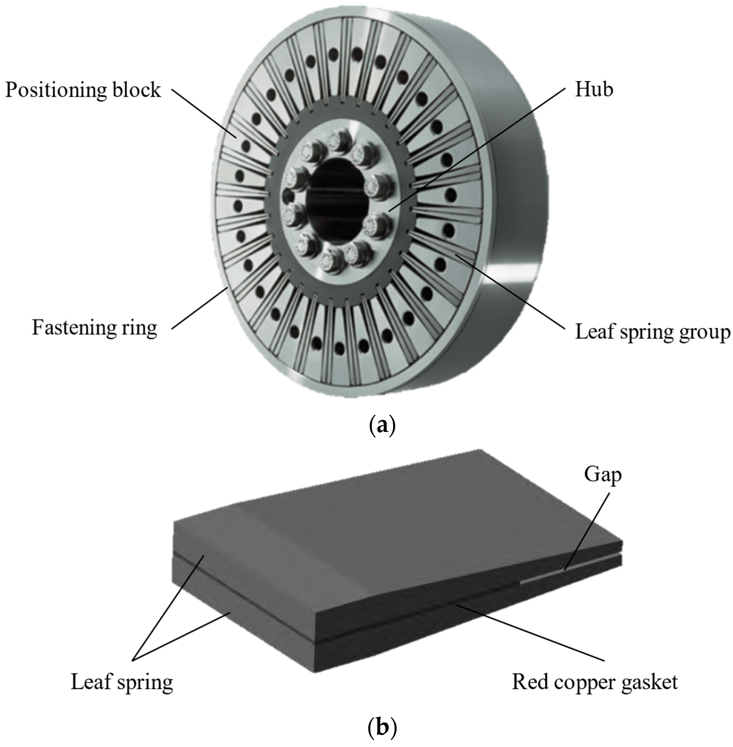
2. Structure and Parametric Model of Leaf Spring Torsional Vibration Damper
3. Mechanical Modeling
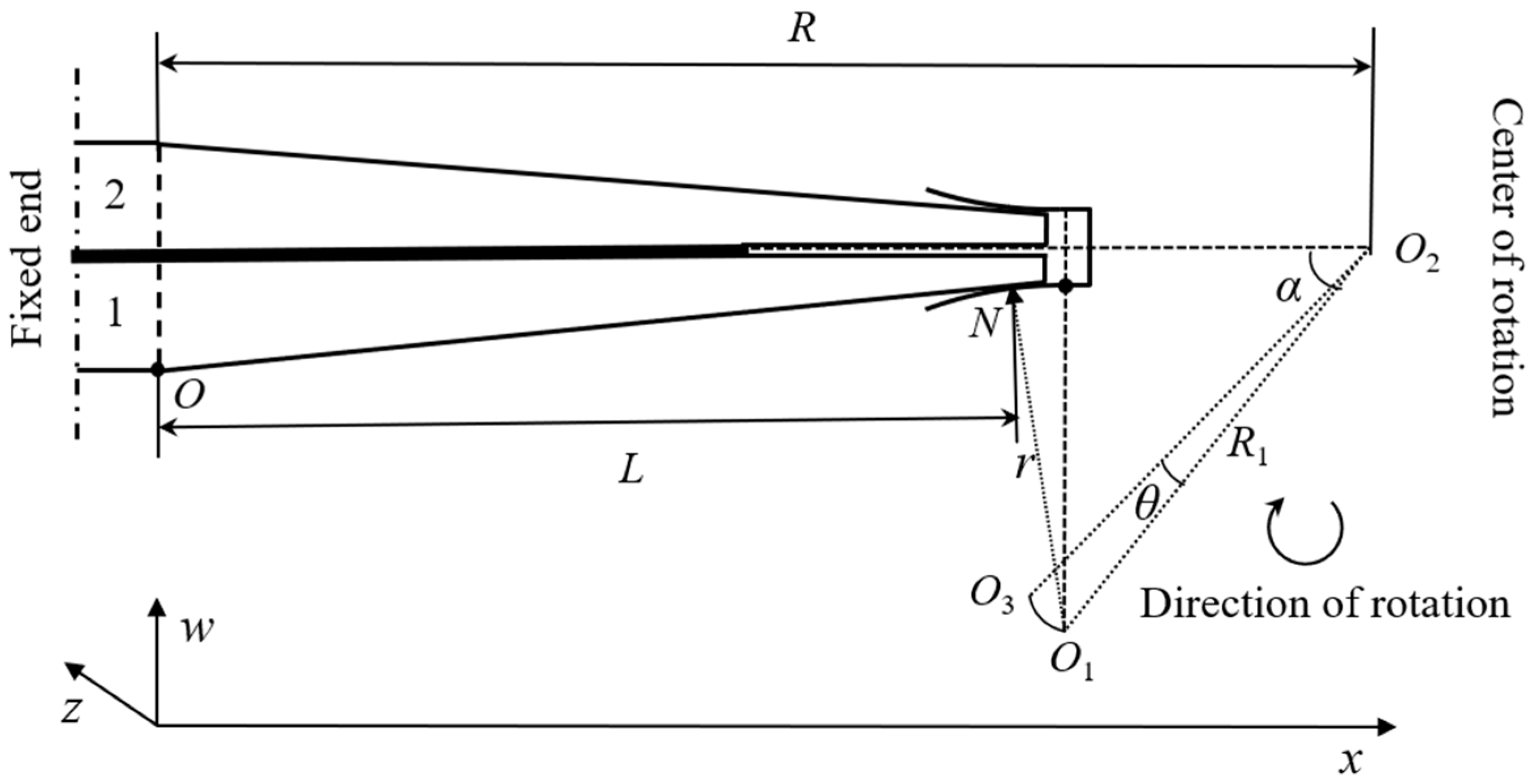
3.1. Modeling for Leaf Spring Group Deformation
3.2. Modeling for Torsional Stiffness
4. Verification of Model
5. Analysis for Torsional Stiffness Properties of Leaf Spring Torsional Vibration Damper
5.1. Influence of Clamping Groove Arc Radius on Torsional Stiffness Properties
5.2. Influence of Leaf Spring Size on Torsional Stiffness Properties
5.3. Influence of Red Copper Gasket Length on Torsional Stiffness Properties
6. Conclusions
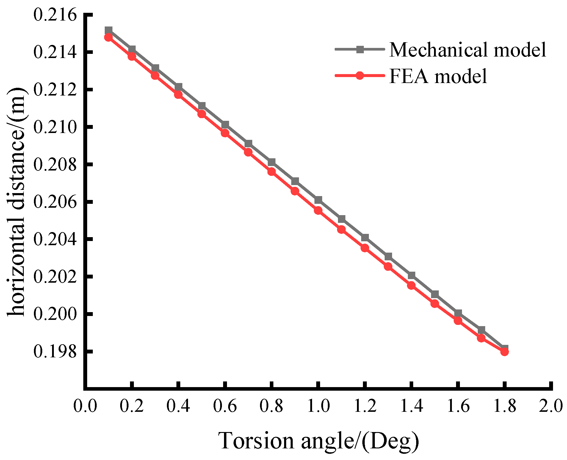
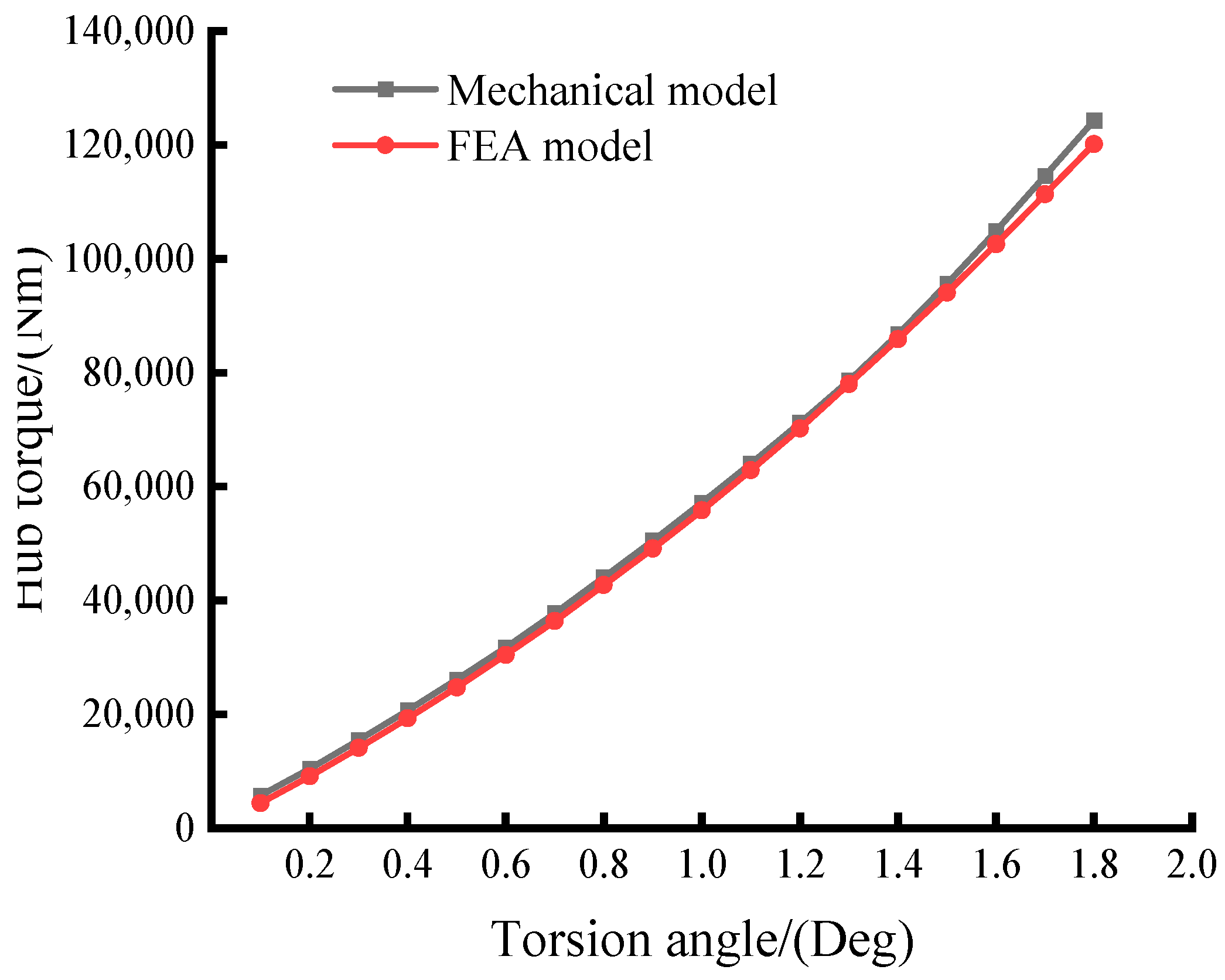
- (1)
- The analytical outcomes from the mechanical model proposed in this article exhibit a high level of concordance with the results obtained through finite element analysis, validating the reliability of the model. The model can not only compute the torsional stiffness of the damper but also facilitate the study of how design parameters affect the torsional stiffness characteristics, thereby assisting in the design of dampers.
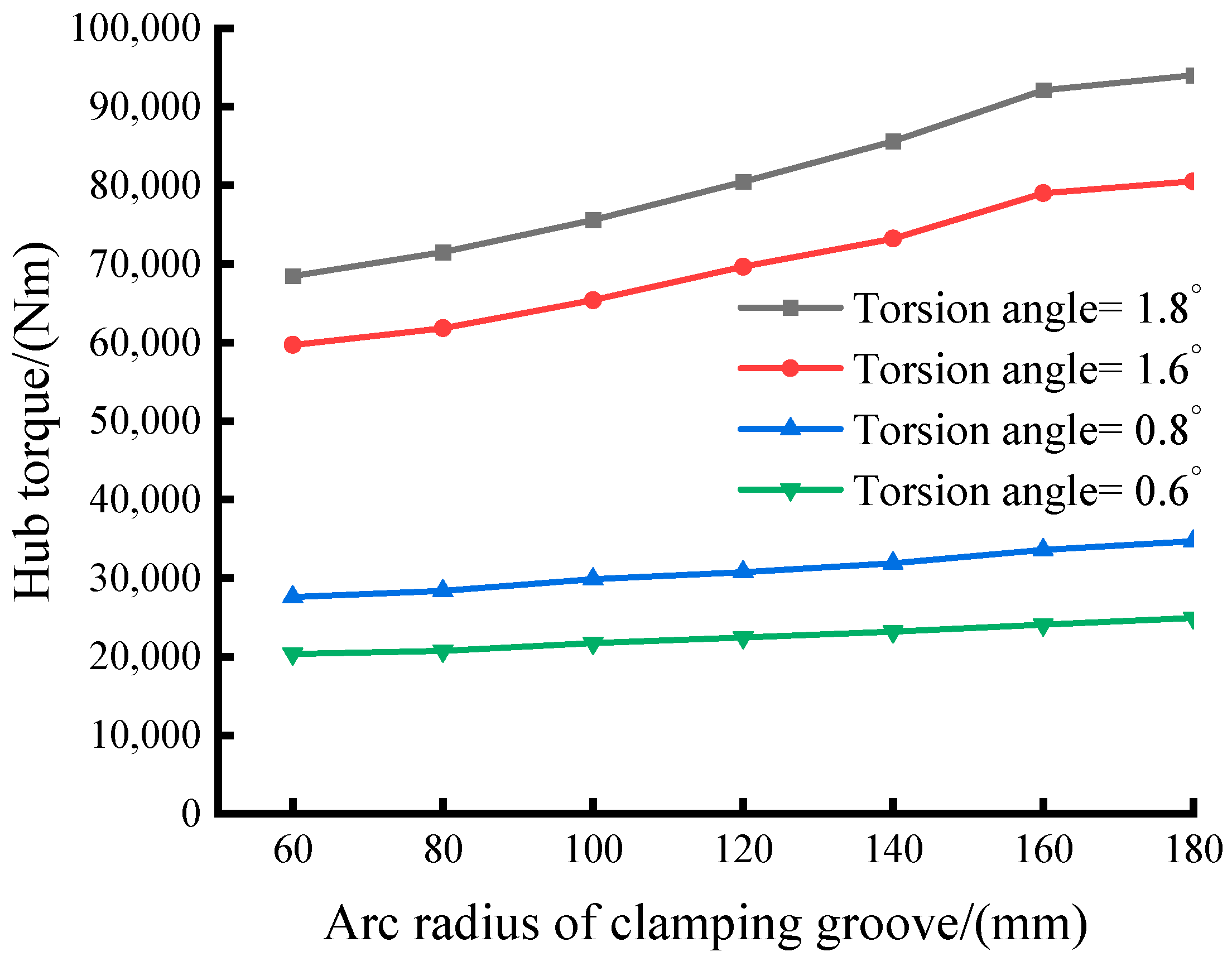
- (2)
- The damper’s torsional stiffness and nonlinear features undergo significant influence from the clamping groove arc radius. Specifically, nonlinear traits become more pronounced with increasing arc radius. This serves to prevent damage and failure due to excessive torsion angles within the damper.
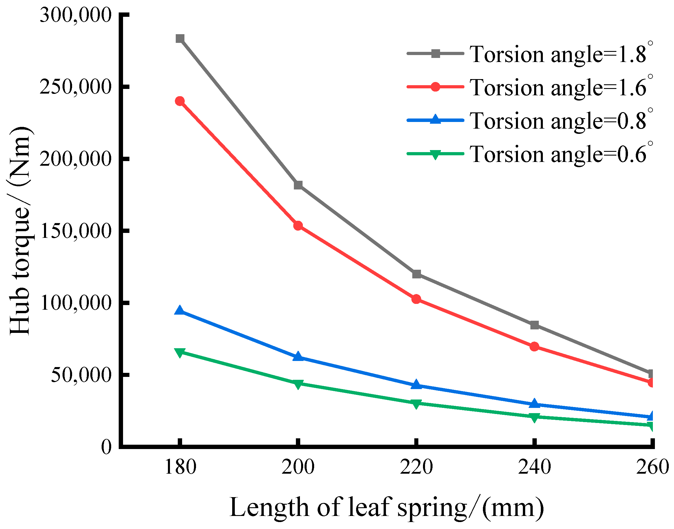
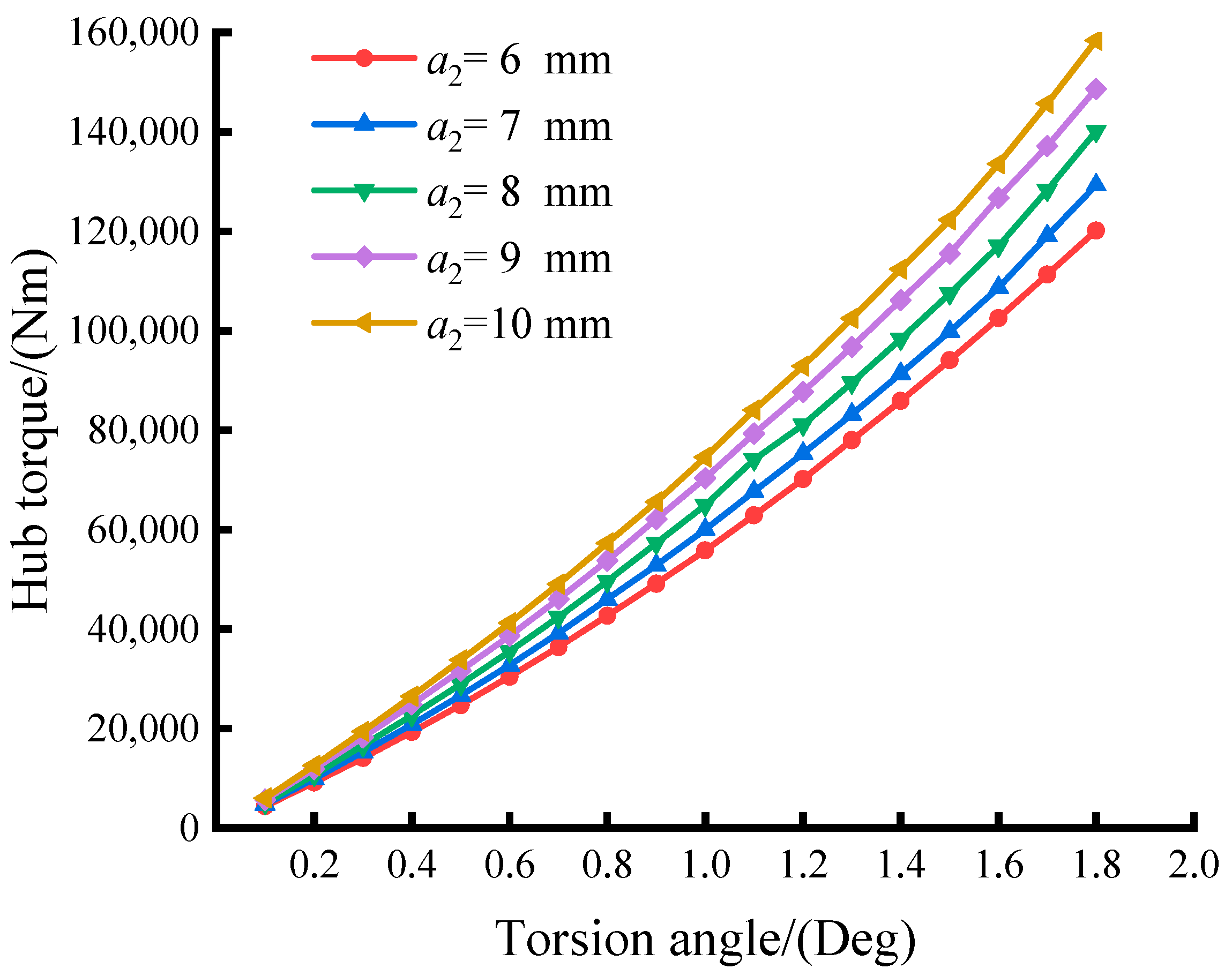
- (3)
- The length of the leaf spring significantly impacts the damper’s torsional stiffness. Longer leaf springs result in reduced stiffness within the leaf spring group, sharply diminishing the damper’s torsional stiffness and displaying pronounced nonlinear characteristics. Leaf spring thickness minimally affects the damper’s nonlinear characteristics but strongly influences its torsional stiffness. Decreasing the thickness of the leaf spring’s thin side leads to a reduction in the damper’s torsional stiffness.
- (4)
- The length of the red copper gasket minimally affects the damper’s torsional stiffness nonlinearity but moderately influences its stiffness.
- (5)
- During the design of leaf spring torsional vibration dampers, attention must be given to the impact of clamping groover radius, spring length, and spring thickness on torsional stiffness and its nonlinear characteristics. If researchers observe a significant deviation in torsional stiffness from the anticipated value during the design phase, their priority should be adjusting the spring length, followed by reasonable adjustments to other parameters. Additionally, the impact of the red copper gasket length on torsional stiffness can be taken into account, but there is no need to consider its influence on the nonlinear characteristics of torsional stiffness.
Author Contributions
Funding
Institutional Review Board Statement
Informed Consent Statement
Data Availability Statement
Conflicts of Interest
Appendix A
- (1)
- (2)
- The functions in deflection expressions (19) and (20) are as follows.
References
- Lu, S.; Chen, Y.; Cao, H.; Zhao, G.; Zhang, H.; Guo, Y.; Jiang, C. Coupling effect of shaft torsional vibration and advanced injection angle on medium-speed diesel engine block vibration. Eng. Fail. Anal. 2023, 154, 107624. [Google Scholar] [CrossRef]
- Bian, Y.; Gao, Z.; Hu, J.; Fan, M. A semi-active control method for decreasing longitudinal torsional vibration of vehicle engine system: Theory and experiments. J. Sound Vib. 2019, 439, 413–433. [Google Scholar] [CrossRef]
- Zambon, A.; Moro, L. Torsional vibration analysis of diesel driven propulsion systems: The case of a polar-class vessel. Ocean. Eng. 2022, 245, 110330. [Google Scholar] [CrossRef]
- Zambon, A.; Moro, L.; Oldford, D. Impact of different characteristics of the ice–propeller interaction torque on the torsional vibration response of a Polar-Class shaftline. Ocean. Eng. 2022, 266, 112630. [Google Scholar] [CrossRef]
- Senjanović, I.; Hadžić, N.; Murawski, L.; Vladimir, N.; Alujević, N.; Cho, D.S. Analytical procedures for torsional vibration analysis of ship power transmission system. Eng. Struct. 2019, 178, 227–244. [Google Scholar] [CrossRef]
- Damirovich, I.A.; Petrovich, K.O. Spring dampers of torsional vibrations in modern Marine diesel engines: Advantages and disadvantages. Bull. Astrakhan Natl. Tech. University. Ser. Mar. Eng. Technol. 2023, 66–73. [Google Scholar] [CrossRef]
- Homik, W. Diagnostics, maintenance and regeneration of torsional vibration dampers for crankshafts of ship diesel engines. Pol. Marit. Res. 2010, 17, 62–68. [Google Scholar] [CrossRef]
- Ma, K.; Du, J.; Liu, Y.; Chen, X. Torsional vibration attenuation of a closed-loop engine crankshaft system via the tuned mass damper and nonlinear energy sink under multiple operating conditions. Mech. Syst. Signal Process. 2024, 207, 110941. [Google Scholar] [CrossRef]
- Sezgen, H.Ç.; Tinkir, M. Optimization of torsional vibration damper of cranktrain system using a hybrid damping approach. Eng. Sci. Technol. Int. J. 2021, 24, 959–973. [Google Scholar] [CrossRef]
- Li, Y. Dynamic analysis of torsional vibration of leaf spring damper of diesel engine. J. Phys. Conf. Ser. 2019, 1300, 012050. [Google Scholar] [CrossRef]
- Kim, Y.G.; Lee, M.S.; Cho, K.H.; Kim, U.K. Effects of a turbocharger cut out system on vibration characteristics of a propulsion shafting system and a large low speed marine diesel engine. J. Mech. Sci. Technol. 2017, 31, 3737–3745. [Google Scholar] [CrossRef]
- Wilson, W.K. Practical solution of torsional vibration problems. Phys. Bull. 1956, 19, 278. [Google Scholar]
- Newmark, N.M. Test and analysis of composite beams with incomplete interaction. Proc. Soc. Exp. Stress Anal. 1951, 9, 75–92. [Google Scholar]
- Girhammar, U.A.; Pan, D.H.; Gustafsson, A. Exact dynamic analysis of composite beams with partial interaction. Int. J. Mech. Sci. 2009, 51, 565–582. [Google Scholar] [CrossRef]
- He, G.H.; Yang, X. Nonlinear analysis of composite beams using Reddy’s high order beam theory. Eng. Mech. 2015, 32, 87–95. [Google Scholar] [CrossRef]
- Shen, Z.Q.; Zhong, H.Z. Geometrically nonlinear quadrature element analysis of composite beams with interface slip. Eng. Mech. 2013, 30, 270–275+288. [Google Scholar] [CrossRef]
- Nguyen, Q.H.; Martinelli, E.; Hjiaj, M. Derivation of the exact stiffness matrix for a two-layer Timoshenko beam element with partial interaction. Eng. Struct. 2011, 33, 298–307. [Google Scholar] [CrossRef]
- Kim, T.; Moon, W.; Kim, S. Influences of leaf shapes on performance of progressive multi-leaf springs. Int. J. Veh. Des. 2004, 34, 65–83. [Google Scholar] [CrossRef]
- Qin, Z.M.; Pan, Y.C.; Wang, J.K. Design and calculation of leaf spring with gradual stiffness. Automot. Eng. 1994, 219–224. [Google Scholar] [CrossRef]
- Zhang, L.J.; He, H.; Yu, G.R. New calculation method of leaf spring and its application in design. Automot. Eng. 1994, 50–57. [Google Scholar] [CrossRef]
- Peng, M. Calculation method of leaf spring with gradual stiffness. Automot. Eng. 1993, 350–358. [Google Scholar] [CrossRef]
- Peng, M.; Gao, J. Design and calculation of variable section leaf spring. Automot. Eng. 1992, 156–169. [Google Scholar] [CrossRef]
- Malikoutsakis, M.; Savaidis, G.; Savaidis, A. Design, analysis and multi-disciplinary optimization of high-performance front leaf springs. Theor. Appl. Fract. Mech. 2016, 83, 42–50. [Google Scholar] [CrossRef]
- Kim, S.; Moon, W.; Yoo, Y. An efficient method for calculating the nonlinear stiffness of progressive multi-leaf springs. Int. J. Veh. Des. 2002, 29, 403–422. [Google Scholar] [CrossRef]
- Ekici, B. Multi-response optimization in a three-link leaf-spring model. Int. J. Veh. Des. 2005, 38, 326–346. [Google Scholar] [CrossRef]
- Zhou, S.T.; Huang, H.W.; Ouyang, L.G. Analysis and computation of taper plate spring based on FE contact analysis. Adv. Mater. Res. 2013, 705, 516–522. [Google Scholar] [CrossRef]
- Hu, G.Y.; Xia, P.Q.; Yang, J.S. Curvature load hybrid method for calculating stiffness characteristics of leaf springs with gradual stiffness. Trans. Nanjing Univ. Aeronaut. Astronaut. 2008, 40, 46–50. [Google Scholar] [CrossRef]
- Shi, W.; Liu, C.; Chen, Z. Efficient method for calculating the composite stiffness of parabolic leaf springs with variable stiffness for vehicle rear suspension. Math. Probl. Eng. 2016, 2016, 5169018. [Google Scholar] [CrossRef]
- Zhou, H.; Lin, J.M. Curved beam model of plate spring with variable cross section. J. Hunan Univ. (Nat. Sci.) 1998, 48–52. [Google Scholar]
- Hwang, B.C.; Kim, C.; Bae, W.B. A Study of Structural Analysis and Torsional Characteristic of the Sleeve Spring Type Torsional Vibration Damper. J. Korean Soc. Precis. Eng. 2009, 26, 94–100. Available online: https://koreascience.kr/article/JAKO200907653003532.page (accessed on 18 December 2023).
- Park, S.K.; Gao, X.L. Bernoulli–Euler beam model based on a modified couple stress theory. J. Micromech. Microeng. 2006, 16, 2355. [Google Scholar] [CrossRef]
- Kuo, Y.L.; Cleghorn, W.L.; Behdinan, K. Stress-based finite element method for Euler-Bernoulli beams. Trans. Can. Soc. Mech. Eng. 2006, 30, 1–6. [Google Scholar] [CrossRef]
- Sideris, S.A.; Tsakmakis, C. Consistent Euler–Bernoulli beam theories in statics for classical and explicit gradient elasticities. Compos. Struct. 2022, 282, 115026. [Google Scholar] [CrossRef]
- Ladurner, D.; Adam, C.; Furtmüller, T. Geometric nonlinear analysis of slender layered non-prismatic beams with interlayer slip. Int. J. Mech. Sci. 2023, 261, 108651. [Google Scholar] [CrossRef]
- Girhammar, U.A.; Pan, D.H. Exact static analysis of partially composite beams and beam-columns. Int. J. Mech. Sci. 2007, 49, 239–255. [Google Scholar] [CrossRef]


Disclaimer/Publisher’s Note: The statements, opinions and data contained in all publications are solely those of the individual author(s) and contributor(s) and not of MDPI and/or the editor(s). MDPI and/or the editor(s) disclaim responsibility for any injury to people or property resulting from any ideas, methods, instructions or products referred to in the content. |
© 2024 by the authors. Licensee MDPI, Basel, Switzerland. This article is an open access article distributed under the terms and conditions of the Creative Commons Attribution (CC BY) license (https://creativecommons.org/licenses/by/4.0/).
Share and Cite
Shen, C.; Li, G.; Tian, Z.; Chen, C.; Zhou, Y. Research on Mechanical Model and Torsional Stiffness Properties of Leaf Spring Torsional Vibration Dampers for Marine Diesel Engines. Appl. Sci. 2024, 14, 1304. https://doi.org/10.3390/app14031304
Shen C, Li G, Tian Z, Chen C, Zhou Y. Research on Mechanical Model and Torsional Stiffness Properties of Leaf Spring Torsional Vibration Dampers for Marine Diesel Engines. Applied Sciences. 2024; 14(3):1304. https://doi.org/10.3390/app14031304
Chicago/Turabian StyleShen, Chunyun, Genpei Li, Zhongxu Tian, Chang Chen, and You Zhou. 2024. "Research on Mechanical Model and Torsional Stiffness Properties of Leaf Spring Torsional Vibration Dampers for Marine Diesel Engines" Applied Sciences 14, no. 3: 1304. https://doi.org/10.3390/app14031304
APA StyleShen, C., Li, G., Tian, Z., Chen, C., & Zhou, Y. (2024). Research on Mechanical Model and Torsional Stiffness Properties of Leaf Spring Torsional Vibration Dampers for Marine Diesel Engines. Applied Sciences, 14(3), 1304. https://doi.org/10.3390/app14031304