Article

Design of Wheelchair Drive Unit Capable of Driving on Roads and Obstacles with Shape Conversion

1
Department of Mechanical Engineering, Chung-Ang University, Seoul 06974, Republic of Korea
2
Department of Mechanical & Automotive Engineering, Hanyang Cyber University, Seoul 04763, Republic of Korea
*
Author to whom correspondence should be addressed.
Appl. Sci. 2024, 14(4), 1434; https://doi.org/10.3390/app14041434
Submission received: 17 January 2024 / Revised: 1 February 2024 / Accepted: 7 February 2024 / Published: 9 February 2024

Abstract

:
Wheelchairs are widely used globally and are essential for providing autonomy and mobility to elderly and disabled people who have movement restrictions. Manual wheelchairs require operation through turning the wheels or pushing the wheelchair directly, thus posing mobility limitations for the user and caregiver. In contrast, electric wheelchairs, when used by the user, allow for improved flexibility by operating the wheelchair through a single control mechanism. However, the use of electric wheelchairs poses challenges in accessing areas with stairs and curbs, limiting the range of activity and thereby diminishing the quality of life for users and those reliant on electric wheelchairs. The electric wheelchair developed in this research incorporates a single motor for lightweight design. It uses a wheel travel variation actuator, eliminating the need for synchronization and allowing for low-power operation. This design reduces power loss from the caterpillar’s idling during wheel movement and includes the implementation of a pulley system. The optimal pulley belt length was calculated, and a deceleration device was installed inside the caterpillar, enabling a design that is compact, lightweight, and capable of high deceleration. On paved roads and flat terrain, the electric wheelchair is designed for high-speed travel using two pairs of front omni wheels and drive wheels. For terrains with stairs, speed bumps, unpaved roads, and unavoidable obstacles, the wheelchair is powered by caterpillars. The electric wheelchair developed through the research presented in this paper has verified the reliability of its transmission system through gear stress and deformation analysis. Additionally, an electric wheelchair based on the proposed concept was constructed to validate the drivability, safety, operability, and convenience of its driving unit. Furthermore, a user rode the constructed electric wheelchair to confirm that there were no issues with its drivability.

1. Introduction

Wheelchairs are widely used globally to provide autonomy and mobility to the elderly and people with disabilities who have mobility limitations [1]. Manual wheelchairs require users and their caregivers to have limited mobility because they are operated by turning the wheels or pushing the wheelchair. Electric wheelchairs, however, allow the user to operate the wheelchair through a single control mechanism, improving flexibility [2]. However, using a motorized wheelchair reduces the user’s quality of life and their dependents by making it difficult to access areas with stairs and curbs and limiting the range of motion [3]. Ramps and elevators are being installed in facilities to improve mobility; however, some users find it difficult to go up and down stairs using an electric wheelchair, especially in buildings without elevators. This forces users to stay indoors for long periods, which is detrimental to their mental health and physical rehabilitation. In this case, the development of an electric wheelchair capable of going up and down stairs is extremely beneficial in expanding the range of activities and improving the quality of life [4]. Therefore, the development of an electric wheelchair with the ability to climb stairs is necessary for people with walking disabilities or the elderly who have difficulty walking.
To improve user convenience, various technological research is being undertaken on electric wheelchairs that can climb stairs. Chung-Ang University’s Robotics Engineering Laboratory researched and developed a wheelchair that can climb stairs using a link structure and a mechanical transmission system that rotates the entire driving part through an actuator to change speed [5]. The first mode is driven by a caterpillar, while the second uses wheels. Stable driving is possible by using landing gear and wheels on flat ground, and a caterpillar when climbing stairs. Because both the wheels and caterpillars are driven by a single motor, a lightweight wheelchair can be manufactured. However, wheelchairs have limitations in their reliability when climbing stairs, so a method of climbing up and down stairs using only mechanical mechanisms without electronic control was devised; nonetheless, there is a safety issue, and additional research to supplement this is necessary. Another study looked at designing a Removable Pavement-edge-Climbing Electric Wheelchair (RPCEW) that combined a regular electric wheelchair and a track-based wheel [6]. Track-based wheels can be assembled or detached from wheelchairs, making them useful in various ways, minimizing conversion processes and facilitating transport, enabling them to meet the needs of the elderly and disabled, and improving their quality of life. Another study designed a Stair-Climbing Mobility System (SCMS), which combines four wheels and two sliding support mechanisms for traction control, with each overcoming stair obstacles [7]. SCMS initially scans the staircase surface using a LiDAR sensor, calculates the distance to the staircase, and generates a trajectory plan for climbing the stairs. It is characterized by maintaining stable balance at all times on the stairs, and while the user’s comfort can be improved by controlling the drive motor with a smooth reference trajectory, shaking while moving can cause discomfort to the user, especially in unsafe environments. It is difficult to operate, therefore only experienced people can use it, which is inconvenient. Another study investigated a unique stair-climbing wheelchair operated by the human upper body using lever-propelled rotating legs and a posture-switching mechanism [8]. It provides a mechanism that uses the user’s upper body abilities and increases the functionality of a regular wheelchair without the need for complex and expensive mechanisms or electric motors. It has manual wheels with casters for flat ground movement and a rotating leg mechanism with lever propulsion control for stair climbing. Afterward, we intend to conduct real-world verification experiments on wheelchair users to confirm their effectiveness. As introduced, we can see various technological research and development efforts on electric wheelchairs that can climb stairs.
Electric wheelchairs that can climb stairs are being commercialized and distributed, making them more user-friendly. The iBOT electric wheelchair is known for its unique features and cutting-edge technology. The iBOT PMD (Personal Mobility Device) may operate in six different modes: standard mode, balance mode, four-wheel mode, docking mode, remote mode, and stair mode [9]. Using four large wheels, you can move various terrain features, adjust the height so you can move with eye contact, and climb up and down stairs. However, depending on the high price and the personality of some users, using the standard functions may feel somewhat difficult. TopChair-S is an electric wheelchair designed for disabled or mobility-impaired users, to safely overcome stairs and similar obstacles, and is focused on significantly improving mobility and independence [10,11]. You can control various functions with a joystick while looking at the LCD screen. It automatically detects the beginning and end of stairs and keeps the user in a horizontal position by going up the stairs backward and going forward down the stairs. However, it is more expensive, heavier, and bulkier than standard electric wheelchairs, making it harder to store and use in narrow spaces. Furthermore, if there are stairs or slopes above a certain height, use may be restricted, making it difficult for users.
In this study, one of the problems of the electric wheelchair [5] introduced earlier was solved using two motors by controlling the position of the front wheel landing gear using a linear actuator, however, this type of drive mode switching is not very reliable. The reason is the synchronization of the two actuators connected to the landing gear and the heavy load placed on the landing gear. These two issues can cause significant damage even in a small frontal collision in driving mode, which can be fatal in any driving mode, and the load due to the caterpillar’s idling increases in driving mode, resulting in extremely low efficiency. We addressed all of the problems mentioned above, presented a new improved caterpillar-wheel driving design, and researched and developed an electric wheelchair that is convenient to use.
The electric wheelchair in this study was designed with a shifting system and a pulley position change system to allow for two driving modes. The transmission’s gear specifications and the pulley position conversion system can be determined via mathematical calculations. The transmission system’s reliability was confirmed using gear stress and deformation analysis, and the proposed concept electric wheelchair was designed to test the drivability, safety, operability, and convenience of the driving part.

2. Electric Wheelchair Design

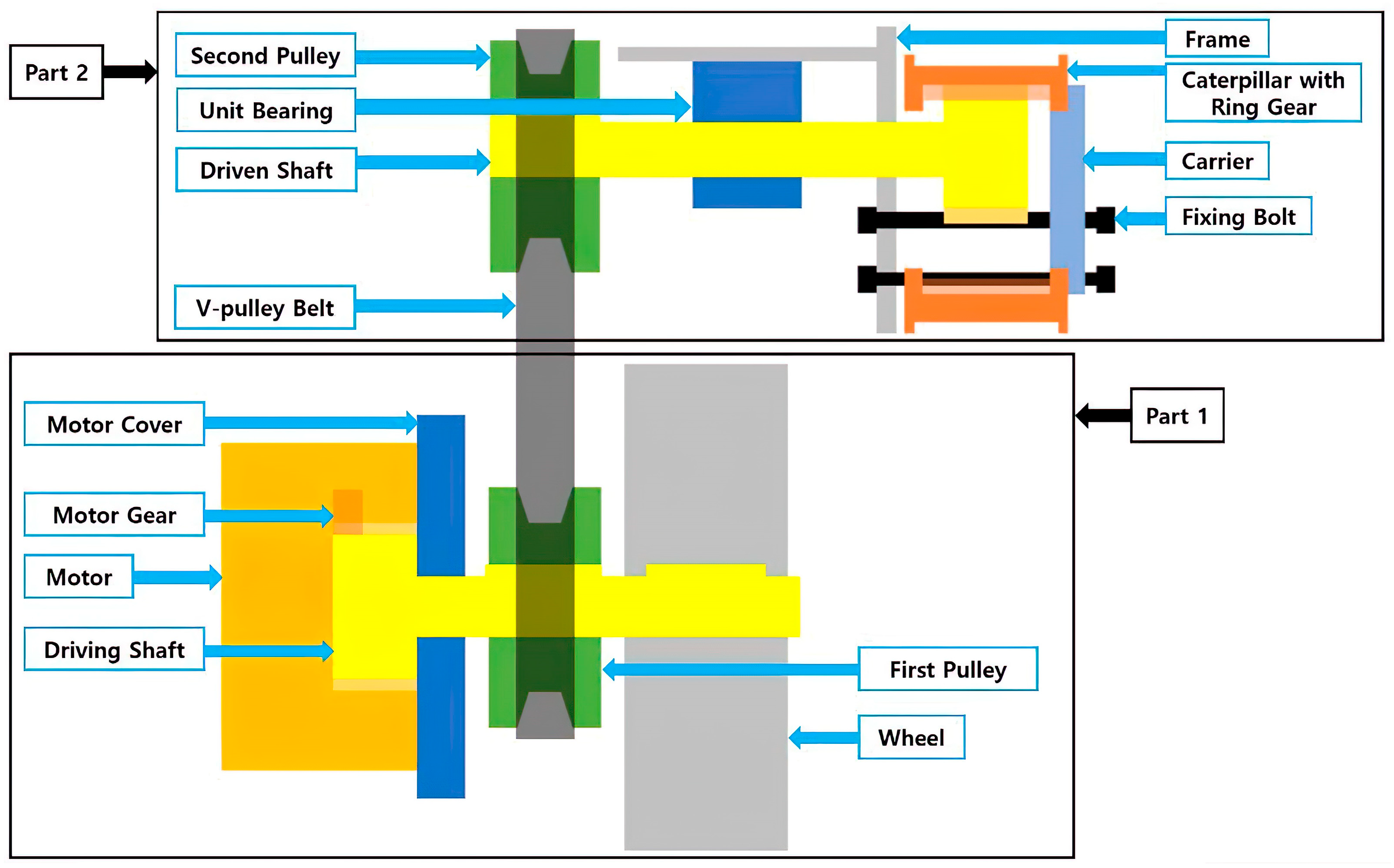
2.1. Power Transmission System of Electric Wheelchair

The proposed electric wheelchair has two deceleration systems when driving. It can be divided into Part 1 and Part 2. Part 1 represents the power transmission system when driving in wheel mode. When the drive is transmitted from the input shaft motor to the gear on the driving shaft, deceleration occurs first, followed by power transmission to the rear wheels. Part 2 represents the power transmission system when driving a caterpillar. The first pulley is powered by the driving force generated in Part 1, which is transmitted to the second pulley via the V-pulley belt. The driven shaft transmits this power to the caterpillar via ring gear, and the ratio of the ring gear teeth to the driven shaft teeth achieves secondary deceleration. The fixing bolt fixes the carrier in the same phase, and the carrier aids in the transmission of power to the caterpillar via the ring gear. The relevant shifting system, the first pulley of Part 1 and the Second pulley of Part 2 will be discussed because power transmission based on distance is a major part of the research. Figure 1 shows a schematic of an electric wheelchair’s power transmission system.

2.2. Efficiency Based on System Gear

Calculating a gear’s baseline efficiency is useful since it indicates how the system’s efficiency changes. Therefore, after the gear specifications are finalized, the calculated reference efficiency can be used to determine the approximate efficiency of the transmission drive mechanism. And gear meshing ratio is an important factor that affects gear performance, vibration, strength, and rotation. Generally, gears with a high meshing ratio produce less noise and vibration, have more flexible rotation, and are stronger. Furthermore, the gear meshing ratio can be used to obtain the gear’s standard efficiency, which can be used to check how the efficiency of the system varies [12].
To calculate the gear reference efficiency, the gear engagement ratio must first be calculated. Equation (1) is a formula for calculating the gear engagement ratio. The first and second terms represent the difference in effective radii of the first and second gears, respectively, which may contribute to displacement or strain in gear engagement. The a x s i n ( a b ) term takes into account additional displacement or external force or angle. The denominator’s π m cos ( a 0 ) adjusts the overall strain by considering the gear’s basic dimensions and pressure angles. So, it can be used to calculate engagement ratio or efficiency in the design or analysis of a particular gear system, and several factors such as gear size, shape, and installation angle are considered. Equation (2) can be used to calculate the approach engagement ratio, and Equation (3) calculates the retreat engagement ratio and combining Equations (2) and (3) gives the total engagement ratio. Equation (6) is a formula for calculating gear-based efficiency [13].
ε = d k 1 2 2 d g 1 2 2 d k 2 2 2 d g 2 2 2 + a x sin a b π m cos a 0
ε 1 = Z 2 2 π ( tan a b tan a k 2 )
ε 2 = Z 1 2 π ( tan a k 1 tan a b )
cos a k 1 = d g 1 d k 1 = Z 1 Z 1 + 2 + 2 x 1 cos a c
cos a k 2 = d g 1 d k 2 = Z 2 Z 2 + 2 + 2 x 2 cos a c
η = 1 μ π 1 z 1 1 z 2 ε 1 2 + ε 2 2 + 1 ε 1 ε 2 1 < ε < 2
Gear reference efficiency was calculated using the formulas described above. The results are summarized in Table 1.

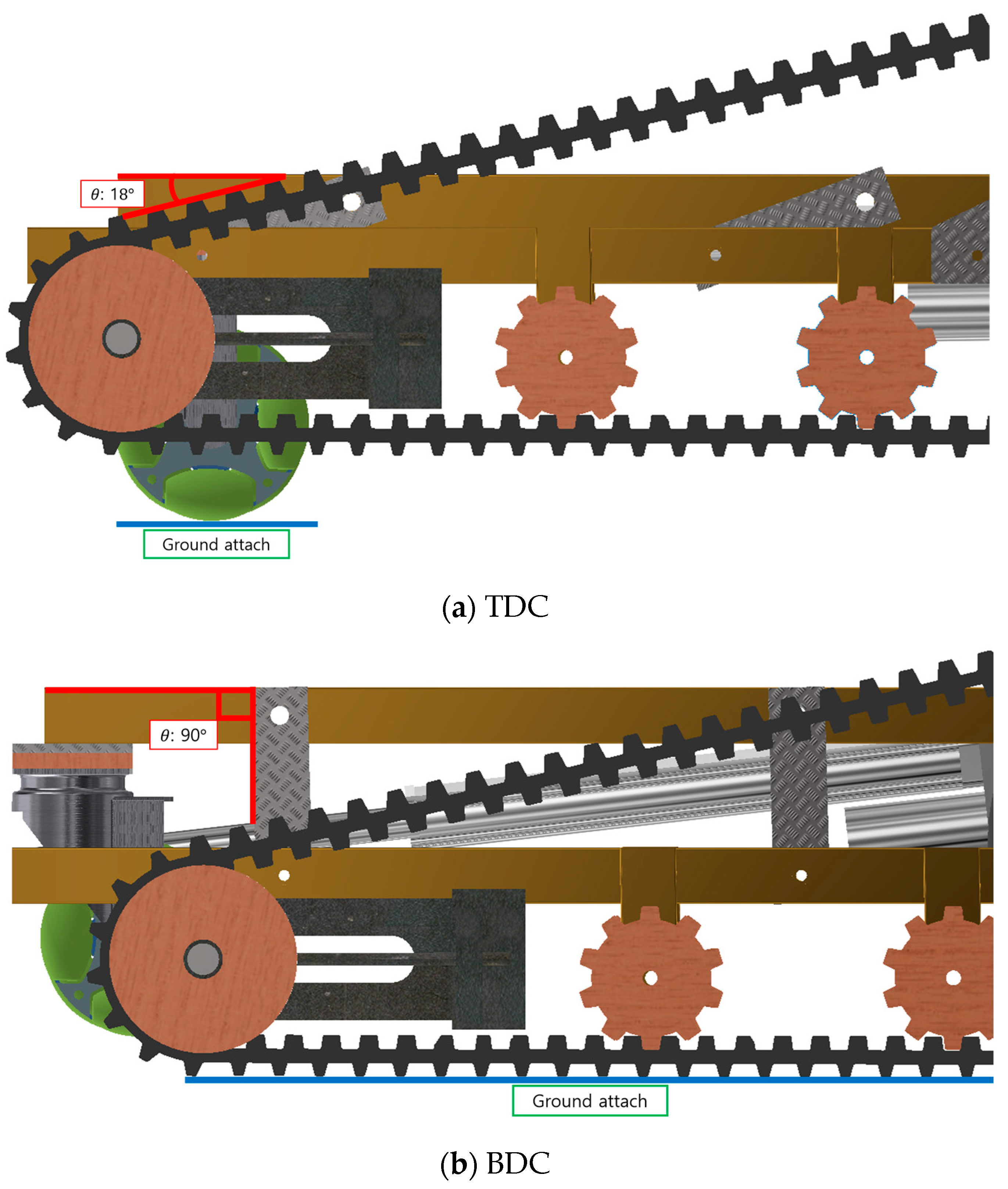
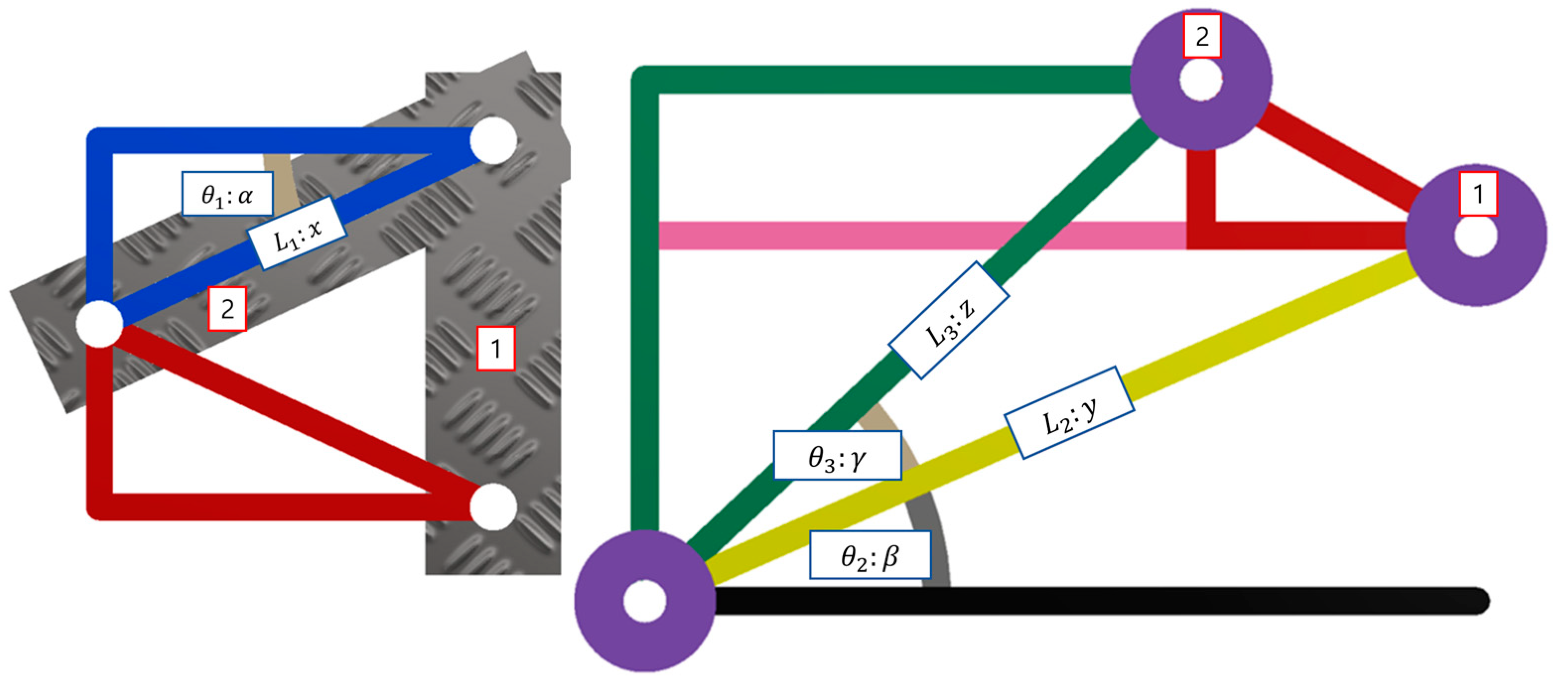
2.3. Drive Mode Mechanism

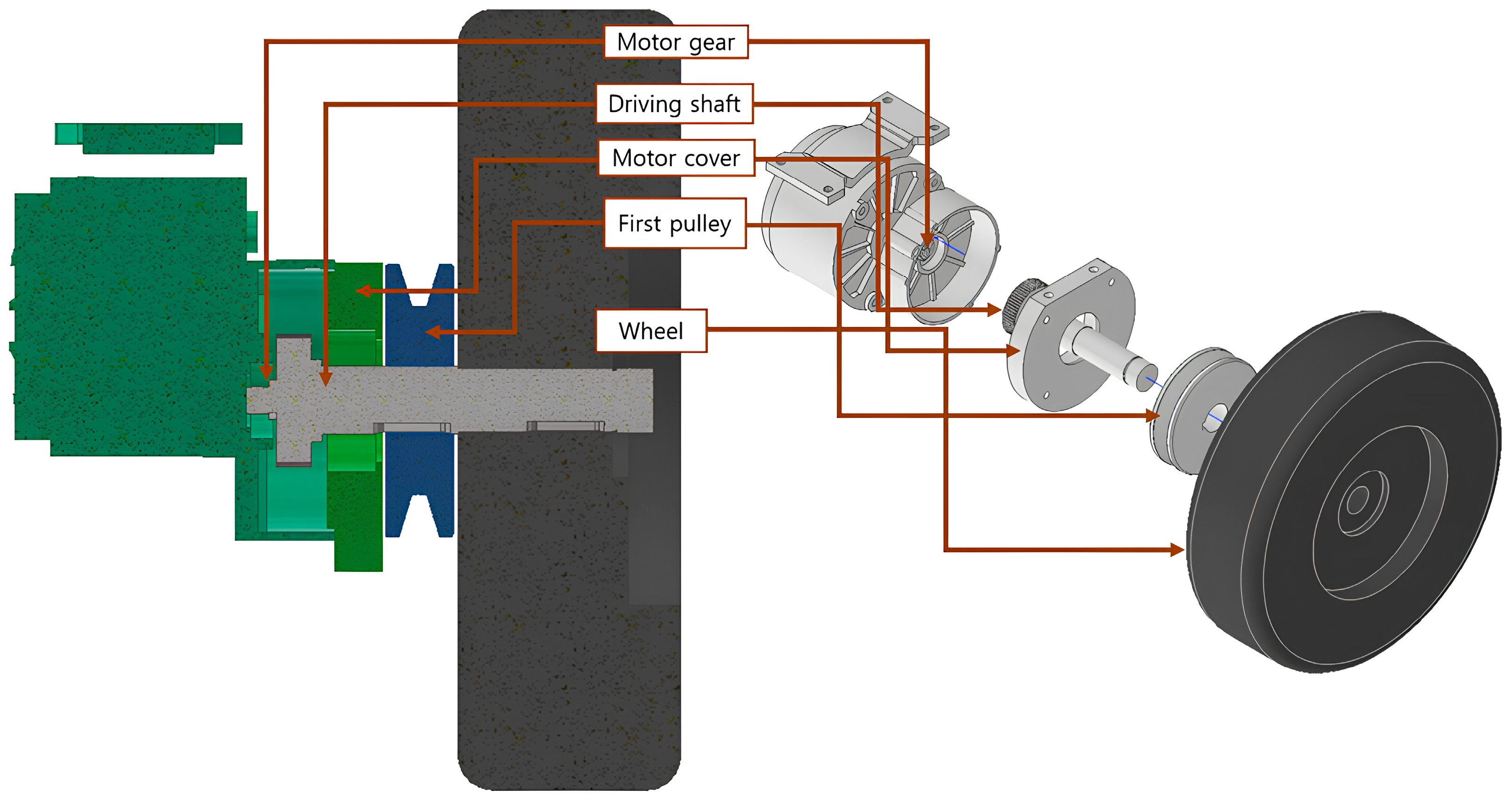
2.3.1. Wheel Drive Mode Mechanism in Part 1

The motor used in the wheel drive mechanism is the MY1016Z2. The output shaft connected to the Gearmotor via the basic reduction device was removed, and further reduction was achieved by processing and installing the driving shaft. The motor specifications are summarized in Table 2, while Figure 2 is a 3D model of the schematic wreath component in Part 1 of Figure 1, with a half-sectional view and an exploded view of the transmission installed on the motor.

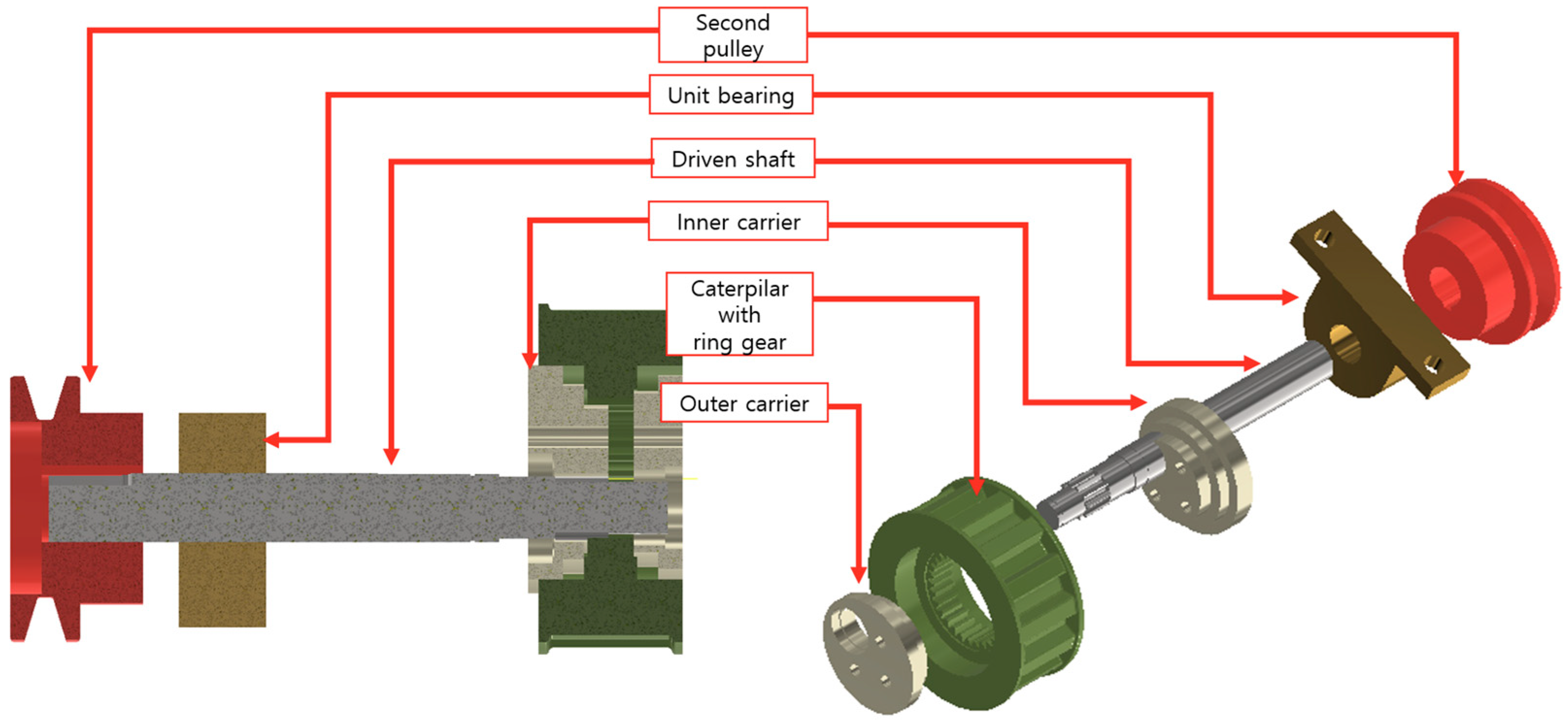
2.3.2. Caterpillar Mode Mechanism in Part 2

The most important mechanism in Part 2 is the pulley system. The pulley system transfers the power generated by the motor to the wheels more efficiently and uses less energy, extending battery life. By adjusting the size of the pulley, the speed can be controlled, allowing the user to drive safely without experiencing any acceleration and braking issues. And Figure 3 is a 3D modeling of the schematic ring part in Patr 2 of Figure 1, showing the half cross-sectional and decomposition diagram of the pulley system. The length of the available pulley belt is determined by precise calculations. In this system, two types of conversion are possible, as shown in Figure 4. The first is (a) Top Dead Center (TDC), whereas the second is (b) Bottom Dead Center (BDC). In TDC mode, there is no power transmission because the actuator and ground are at an angle of 18° and the pulley belt is loose. In BDC mode, the ground and the link form a 90° angle and tension is generated on the pulley belt to transmit power. And by using an actuator, only the secondary deceleration part installed on the outer frame changes the phase without changing the position of the parts installed on the driving shaft, so a large force is not required, and as a result, good efficiency can be achieved. By being able to drive with less force (power), the operating speed of the actuator can be increased, which can show faster control performance in mode changes. Table 3 shows the actuator’s specifications.
Figure 5 schematically illustrates the shape that occurs when the phase of the pulley system changes. The image on the left shows how the angle between the link and the ground changes due to the actuator’s tensile behavior. The upper hole of the link is stationary, while the lower hole connects to the outer frame to transform the driving force via phase change. The image on the right shows the behavior of the pulley on the right side of the system.
The goal is to obtain the optimal z, where z is the center distance between the pulleys at TDC and y is the center distance between the pulleys at BDC. Equation (7) can be used to explain the z-axis phase change of the pulley when moving from BDC to TDC where alpha is the inclination angle to the ground and the CCW.
z P M = x x × sin ( α )
z denotes the hypotenuse of the green right triangle, and we need to know the length of the line perpendicular to the base of the green triangle. It can be expressed as Equation (8).
z V L = x x × sin α + y × sin β
And using the definition of odd angles,
sin β + γ = x x × sin ( α ) + y × sin ( β ) z
It can be defined by Equation (9). Based on the formula defined earlier, if we organize it with z, we get:
z = x x × sin ( α ) + y × sin ( β ) sin β + γ
It can be summarized with Equation (10). The above formula can calculate the range of belt lengths available, but it must be within the range of inequality (11) to meet the prerequisite that the TDC does not deviate from the pulley guide due to its location.
y t < z < y
We used the MATLAB for students program to plot the graph in Figure 6a. The graph’s solid blue line represents a linear equation with z and y lengths as variables. The fluorescent thickness line represents the effective range of the distance between pulleys, calculated using Equation (10). Therefore, the suitable length range of z can be defined using inequality (12).
235.181 < z < 267.077
As above, the range of z has been determined, and assuming t/2 as the optimal length to reduce manufacturing errors,
z = y t 2
You can get a result of z = 251.129 mm. This was confirmed by applying it to the belt length of the electric wheelchair system we developed.

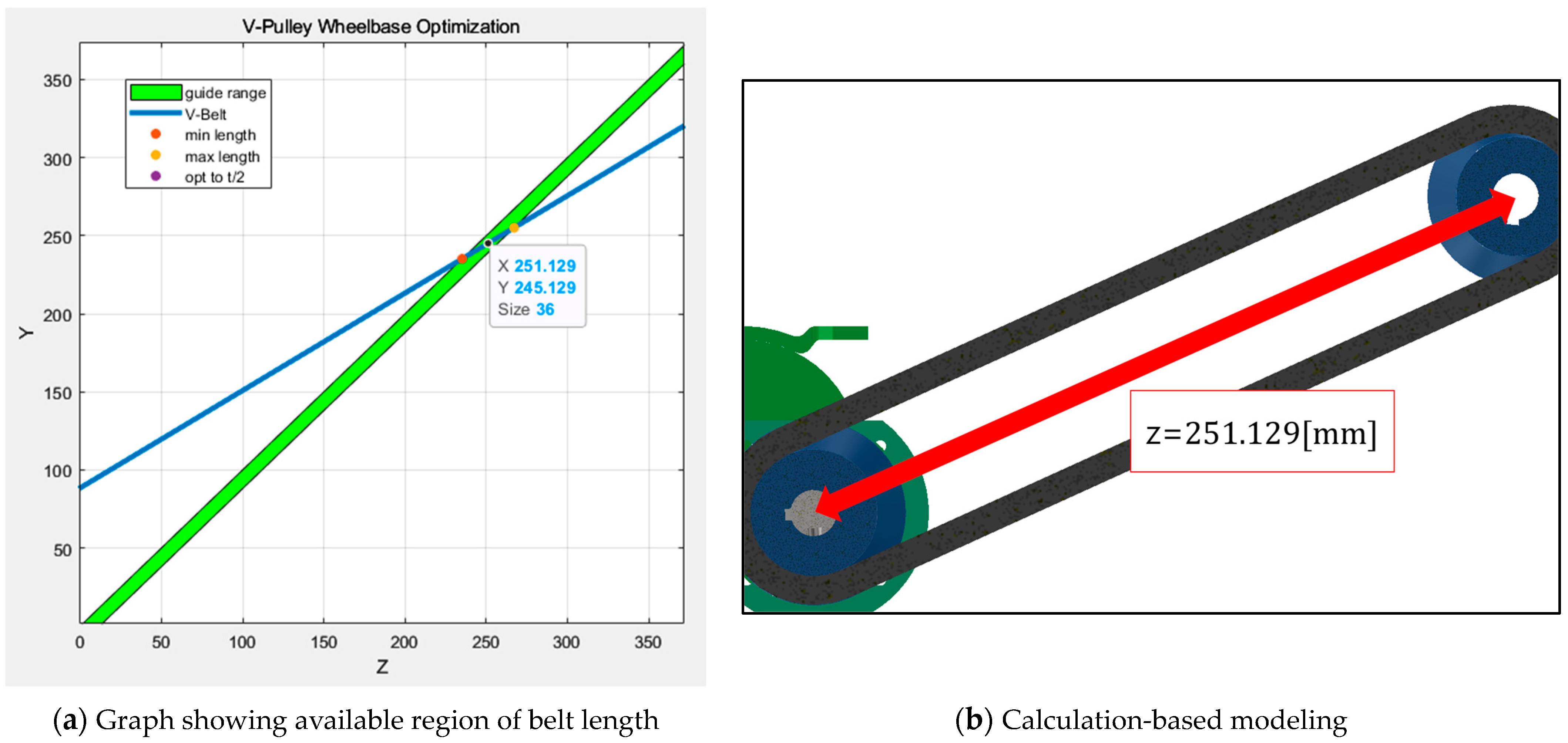
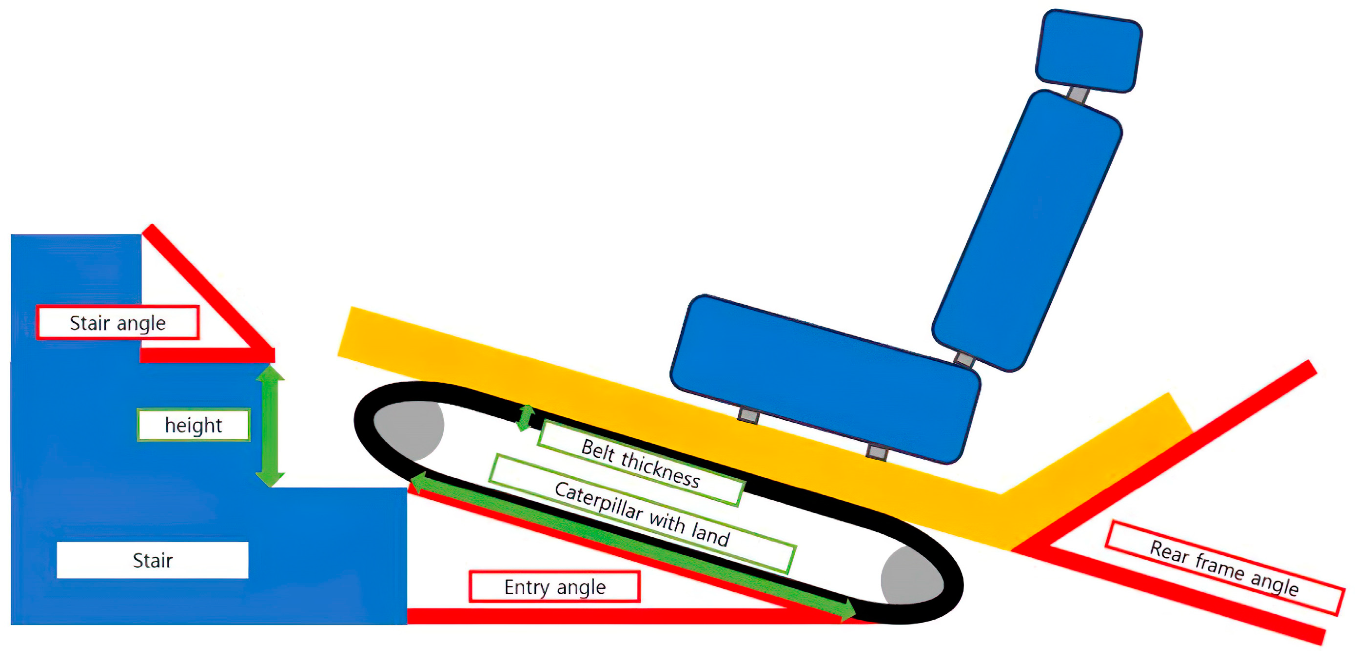
2.4. Key Points in Optimal Design of Electric Wheelchair

In this study, we intend to proceed with the design based on the extremely steep staircase situation extracted from previous research publications [14]. Designs assuming extreme conditions demonstrate robustness in overcoming unstructured obstacles and system rollover [4].
θ = Arctan h ( r + t ) l × 180 π [ θ ]
h: Stair height
r: Caterpillar radius
t: Belt thickness
l: Caterpillar attach with land
Equation (14) presents a methodology for determining the stair-entry angle, taking into account the overall height and length of the system. The caterpillar radius and belt thickness reduce the height, making steep slopes gentler. However, as the caterpillar size increases, the system’s weight and overall height increase, requiring rational design. If you encounter an obstacle while driving in an unobstructed area, you must be able to overcome the first step between the obstacle and the caterpillar. According to the equation, the more parts of the belt are in contact with the ground, the greater the frictional force and the ability to overcome obstacles by reducing the angle of entry. The maximum length at control factor 1 is 500 mm, excluding the 335 mm motor installation area. Next, consider the most severe inclination angle observed in the step elevation tests relevant to our study (41.3°) [14]. Assuming a width of 300 mm (the same as commercial stairs), ‘h’ equals 263.55 mm. The entry angle between ‘h’ and ‘l’ is 23.59°, therefore, we selected a rear frame angle of 24°, which has the lowest bending angle for processing and manufacturing errors. Let’s make this our second control element. Based on this, a suitable caterpillar was designed with a radius (r) of 30.0356 mm and a diameter of 60 mm. To aid in understanding what has been previously explained, it is illustrated in Figure 7.

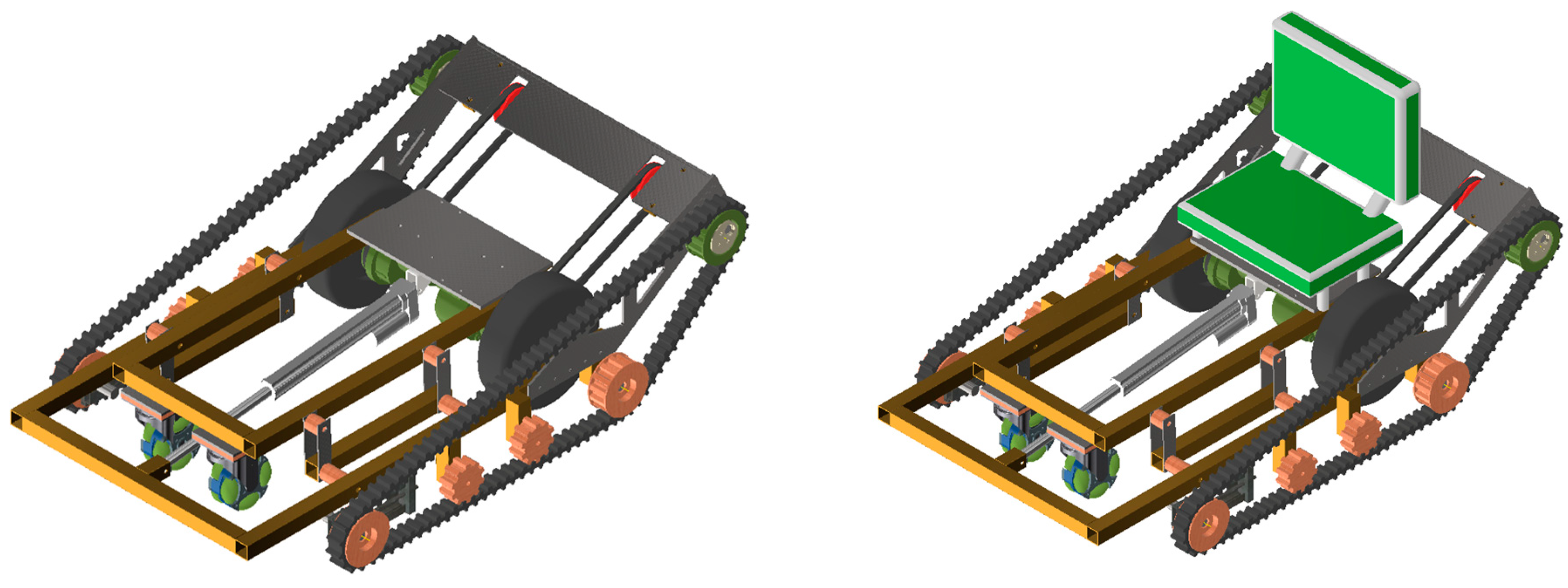
2.5. Electric Wheelchair Concept Design
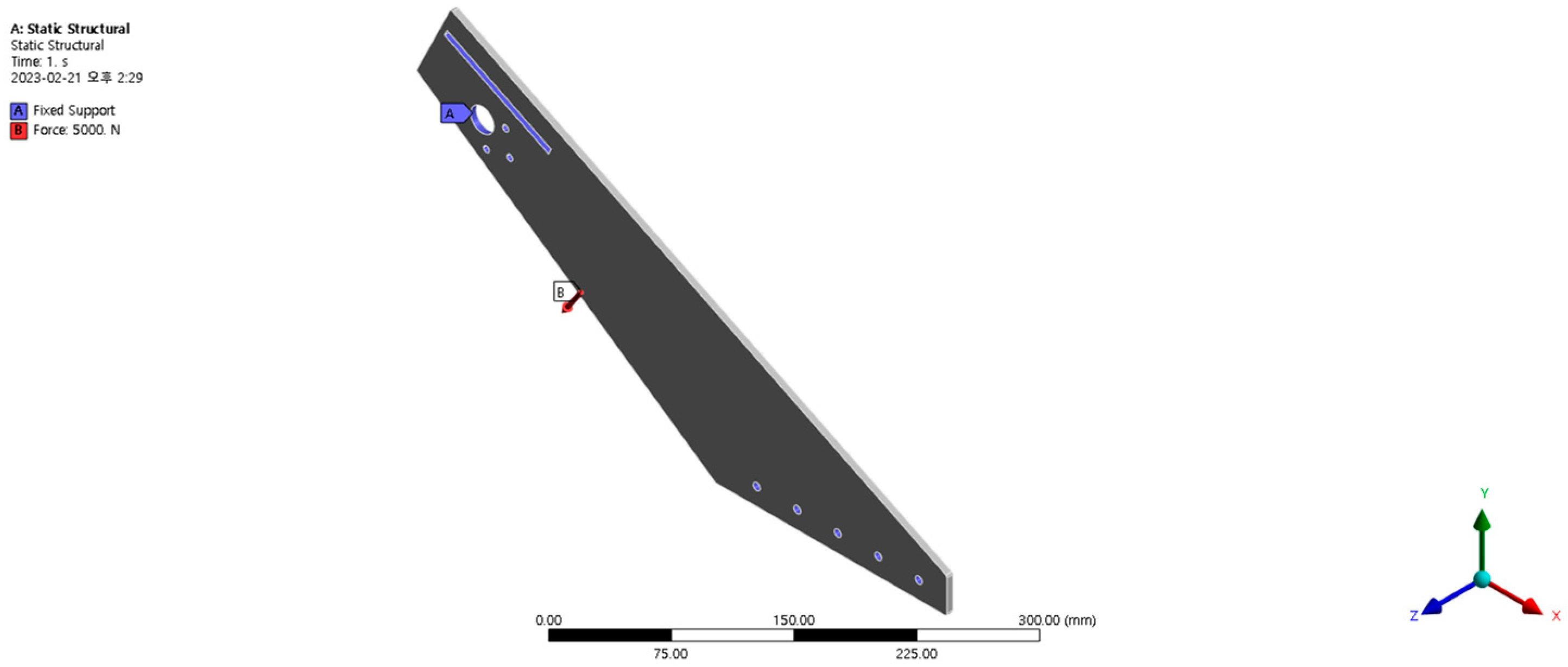
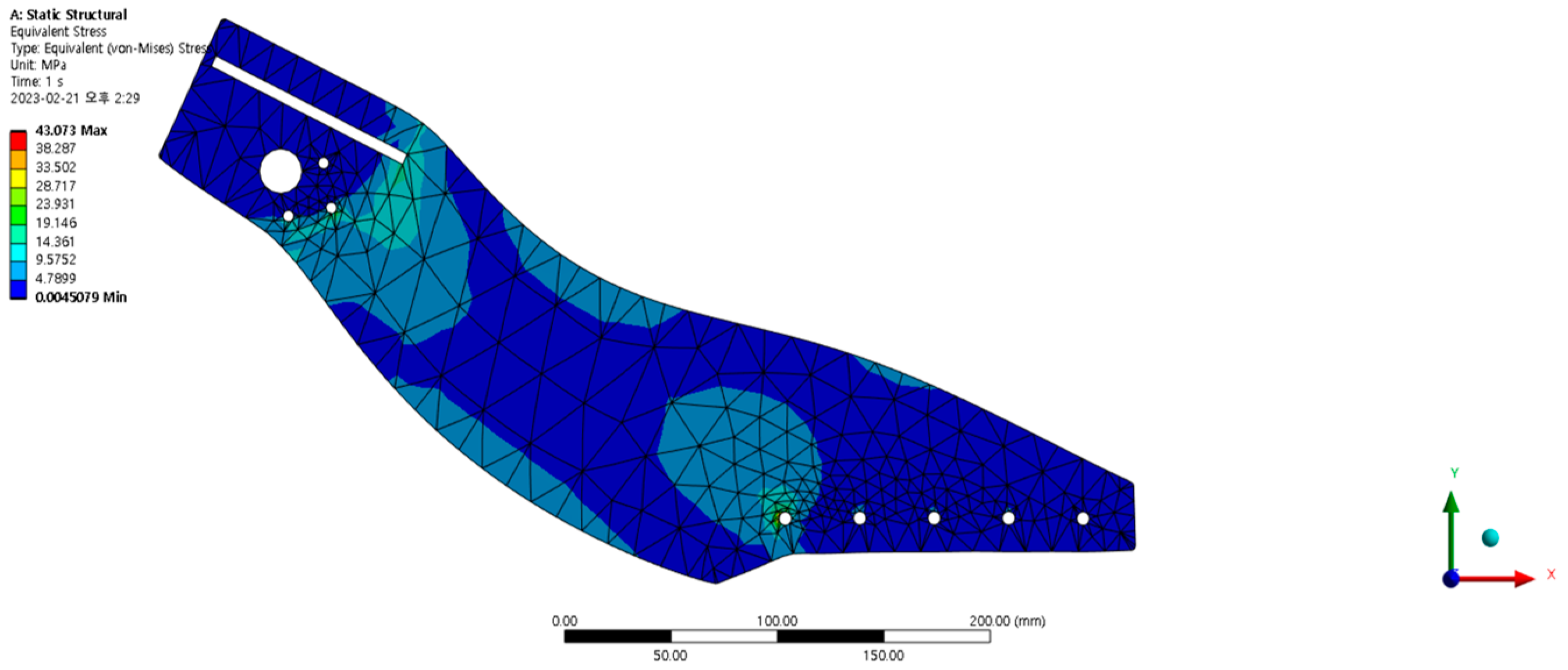
The existing two-type driving devices are heavy because they have separate motors for both wheels and caterpillars [15]. The proposed electric wheelchair drive concept is lightweight because it uses a single motor. By reducing the two linear actuators used when changing wheel travel to one, synchronization between actuators is avoided, and it can be driven at low power, reducing power loss due to the caterpillar’s idling when driving wheels. A deceleration device is installed inside the caterpillar, making it compact, lightweight, and capable of high deceleration. It travels at high speeds on paved roads and flat surfaces with its two pairs of front omni and drive wheels and caterpillar drive on terrain with stairs, bumps, unpaved roads, and unavoidable obstacles. Omni wheels have the advantages of multi-directional mobility (back and forth, left and right), precise positioning, smooth direction changes, 360-degree rotation, various application possibilities, and efficient use of space, making them especially useful for maneuverability and precision work in narrow spaces. Due to these features, it is widely used in various industries and application fields and was also suitable for the electric wheelchair we intended to develop. The proposed electric wheelchair’s driving method achieves high deceleration through two decelerations (deceleration in the driving motor and internal deceleration in the driving caterpillar), enabling immediate overcoming with a large driving force. When overcoming uphill obstacles, two pairs of miniature caterpillars were installed to distribute the impact load absorbed when the front part facing upward contacts the ground. This improves belt deflection and power transmission, which could not be solved with belt tension alone. The extended rear caterpillar belt, which has a 24° angle with the ground, is designed to prevent shock and enable a stable descent when overcoming downhill obstacles. Figure 8 shows the proposed electric wheelchair concept as a 3D model.

3. Stress Analysis

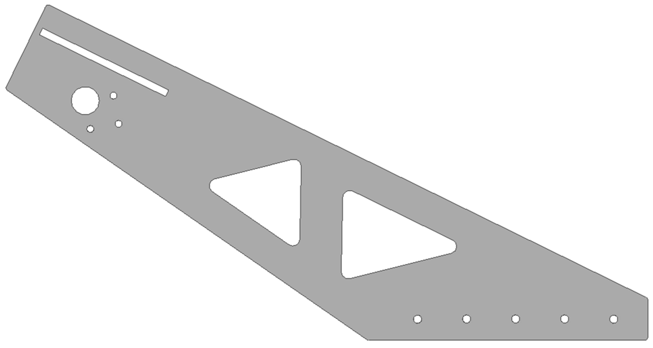
3.1. Frame Optimal Design

A frame is a component that forms the basic skeleton of a structure or machine. The optimal design maximizes structure, safety, and durability while reducing the usability and cost of materials, which has the advantage of increasing energy efficiency. To make an electric wheelchair, a suitable material for the body frame must be selected. Square steel pipes, for example, are structurally efficient in terms of material ductility and bending rigidity, with the added advantage of reducing the number of members and weight [16]. However, steel pipe welding is used in areas where sensitive angles must be maintained, such as the rear frame. The angle generation through is very inaccurate [17]. The rear frame stress analysis was performed using the Ansys’ von Mises program. Ansys’ Von Mises program is useful for predicting material yield and failure and can predict the response of structures under actual operating conditions more accurately, which has the advantage of reducing structure weight or optimizing material use during the design process. Figure 9 depicts the stress analysis conducted using the von Mises criterion in Ansys software (2023 R2). The load applied to the outer wall is 5000 N, and the material properties of the model utilize SCM-440H, with characteristics as presented in Table 4. Figure 10 displays the results.
According to the stress analysis results, holes were used to reduce the load and an optimal design was created, as shown in Figure 11. It is mechanically coupled to the external steel pipe frame, so assembly is expected to be excellent, and the rear frame is manufactured through precision laser processing [18].

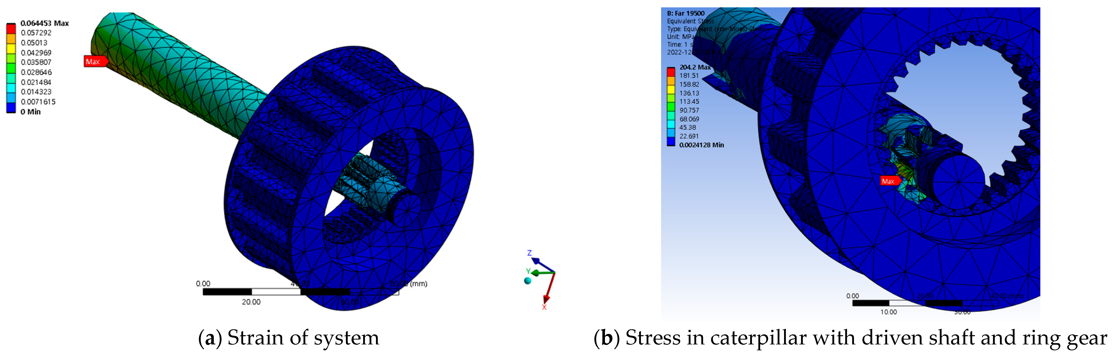
3.2. Gear Stress Analysis

The primary reason for performing gear stress analysis is to ensure gear performance, durability, safety, and reliability. Gears are essential components of mechanical systems that must operate under various loads and motion conditions. This analysis is an essential process in the design, manufacturing, and operation of gears. Gear stress analysis is therefore an important part of the mechanical design process, influencing gear life, safety, and performance. Ansys’ von Mises stress analysis function was used for gear stress analysis. Stress analysis is used to assess the reliability of the reducer’s internal (driven shaft) and external (caterpillar with ring gear) gears. Figure 12 shows the shape used in the stress analysis, while Table 5 summarizes the material properties used.
The material used for power transmission is SCM-440H, and its characteristics are shown in Table 4 [19].
Stress analysis revealed that the maximum stress acting on the ring gear and drive shaft was 204.2 MPa. This can confirm reliability by ensuring that it does not break under extreme conditions that will be used in producing the electric wheelchair drive unit [20,21]. The maximum strain appears at the end of the shaft connected through the pulley and key, with a value of 0.064453 mm, which is very small, allowing cross-verification of safety [22]. Figure 13 is the stress analysis result.

4. Manufacturing Electric Wheelchair

Based on the preceding design details and stress analysis, the electric wheelchair design was modified and supplemented, and parts that were not subject to load were generated using 3D printing and Inventor modeling. The final design sketch was produced, as shown in Figure 14. The wheelchair’s manufactured weight is 40 kg, but the user in Figure 14 weighs 73 kg. To help you understand, please watch our video about driving an electric wheelchair and overcoming obstacles [23].

5. Conclusions

The electric wheelchair developed in this study was made lightweight using a single motor in the preceding research process, and by decreasing the two linear actuators used when changing wheel travel to one, synchronization between actuators was eliminated, and it was driven with low power. This reduced power loss due to the caterpillar idling while driving the wheels and using a pulley system. The optimal pulley belt length was calculated, and a deceleration device was installed inside the caterpillar to enable small size, lightweight, and high deceleration. We designed an electric wheelchair that drives at high speeds on paved roads and flat surfaces with two pairs of front omni wheels and driving wheels and is driven by a caterpillar on terrain with stairs, bumps, unpaved roads, and other unavoidable obstacles. We selected materials suitable for the body frame of electric wheelchairs and conducted an optimal design through stress analysis of the frame using Ansys’ von Mises program. We then used Ansys’ von Mises program to analyze gear stress. The stress analysis revealed that the maximum stress acting on the ring gear and drive shaft was 204.2 MPa, while the maximum strain at the end of the shaft connected through the pulley and key was 0.064453 mm, confirming safety. The electric wheelchair was manufactured after confirming its safety through design and stress analysis. The weight of the electric wheelchair is 40 kg, and the drive delay time is reduced by ensuring that the driving part touches the ground at every moment when changing modes. It has also been demonstrated that it can travel at high speeds on flat ground and reliably overcome obstacles while carrying a user weighing 73 kg. It demonstrated excellent reliability using a single motor rather than a prefabricated caterpillar and attaching a sturdy caterpillar system to the external frame.

Author Contributions

Conceptualization, W.J. and M.K.; methodology, W.J.; software, M.K.; validation, M.K., H.J. and K.Y.; formal analysis, M.K., H.J. and K.Y.; investigation, W.J. and M.K.; resources, W.J.; data curation, H.J. and K.Y.; writing—original draft preparation, W.J.; writing—review and editing, W.J.; visualization, W.J. and M.K.; supervision, S.O.; project administration, S.O.; funding acquisition, S.O. All authors have read and agreed to the published version of the manuscript.

Funding

This research was supported by the Chung-Ang University Research Scholarship Grants in 2022.

Institutional Review Board Statement

Not applicable.

Informed Consent Statement

Not applicable.

Data Availability Statement

The original contributions presented in the study are included in the article, further inquiries can be directed to the corresponding author.

Acknowledgments

This work was supported by the Technology Innovation Program (10084565, Development of smart wheelchair power assist module for outdoor activity and off-road drive of the disabled) funded By the Ministry of Trade, Industry & Energy (MOTIE, Republic of Korea).

Conflicts of Interest

The authors declare no conflicts of interest.

References

  1. Ikeda, H.; Toyama, T.; Maki, D.; Sato, K.; Nakano, E. Cooperative step-climbing strategy using an autonomous wheelchair and a robot. Robot. Auton. Syst. 2021, 135, 103670. [Google Scholar] [CrossRef]
  2. Green, J.; Clounie, J.; Galarza, R.; Anderson, S.; Campell-Smith, J.; Voicu, R.C. Optimization of an intelligent wheelchair: Lidar and camera vision for obstacle avoidance. In Proceedings of the 2022 22nd International Conference on Control, Automation and Systems (ICCAS), Jeju, Republic of Korea, 27 November–1 December 2022; pp. 313–318. [Google Scholar]
  3. Onozuka, Y.; Tomokuni, N.; Murata, G.; Shino, M. Dynamic stability control of inverted-pendulum-type robotic wheelchair for going up and down stairs. In Proceedings of the 2020 IEEE/RSJ International Conference on Intelligent Robots and Systems (IROS), Las Vegas, NV, USA, 24 October–24 January 2021; pp. 4114–4119. [Google Scholar]
  4. Tao, W.; Xu, J.; Liu, T. Electric-powered wheelchair with stair-climbing ability. Int. J. Adv. Robot. Syst. 2017, 14, 1729881417721436. [Google Scholar] [CrossRef]
  5. Lee, J.; Jeong, W.; Han, J.; Kim, T.; Oh, S. Barrier-free wheelchair with a mechanical transmission. Appl. Sci. 2021, 11, 5280. [Google Scholar] [CrossRef]
  6. Phannil, N.; Jettanasen, C. Design and Simulation of Removable Pavement Edge Climbing Electric Wheelchair for Elderly and Disabled Users. Int. J. Control. Autom. Syst. 2023, 21, 1910–1925. [Google Scholar] [CrossRef]
  7. Chocoteco, J.; Morales, R.; Feliu, V.; Sánchez, L. Trajectory planning for a stair-climbing mobility system using laser distance sensors. IEEE Syst. J. 2014, 10, 944–956. [Google Scholar] [CrossRef]
  8. Sasaki, K.; Eguchi, Y.; Suzuki, K. Stair-climbing wheelchair with lever propulsion control of rotary legs. Adv. Robot. 2020, 34, 802–813. [Google Scholar] [CrossRef]
  9. Available online: https://robotsguide.com/robots/ibot (accessed on 22 August 2023).
  10. Available online: https://newatlas.com/topchair-s-stair-climbing-wheelchair/41421/ (accessed on 21 January 2016).
  11. Available online: https://siamagazin.com/the-stair-climbing-power-wheelchair-topchair-s/ (accessed on 18 December 2019).
  12. Han, J.O.; Jeong, W.H.; Lee, J.S.; Oh, S.H. The Structure and Optimal Gear Tooth Profile Design of Two-Speed Transmission for Electric Vehicles. Energies 2021, 14, 3736. [Google Scholar] [CrossRef]
  13. KHK Stock Gears. Gear Technical Reference. Gear Knowledge. Available online: http://khkgears.net/gear-konwledge/gear-technical-reference/ (accessed on 3 April 2021).
  14. Stacoff, A.; Diezi, C.; Luder, G.; Stüssi, E.; Kramers-de Quervain, I.A. Ground reaction forces on stairs: Effects of stair inclination and age. Gait Posture 2005, 21, 24–38. [Google Scholar] [CrossRef] [PubMed]
  15. Gao, J.; Gao, X.; Zhu, J.; Zhu, W.; Wei, B.; Wang, S. Light mobile robot power common technique research. In Proceedings of the 2009 International Conference on Intelligent Human-Machine Systems and Cybernetics, Hangzhou, China, 26–27 August 2009; Volume 1. [Google Scholar]
  16. Available online: https://digi4home.com/gaghyeongganggwan/ (accessed on 26 April 2023).
  17. Kang, S.K.; Yang, J.S. Overview of research works regarding welding distortion. J. Weld. Join. 2012, 30, 37–42. [Google Scholar]
  18. Phillips, K.C.; Gandhi, H.H.; Mazur, E.; Sundaram, S.K. Ultrafast laser processing of materials: A review. Adv. Opt. Photonics 2015, 7, 684–712. [Google Scholar] [CrossRef]
  19. ‘Longhai’ Steels. Available online: https://www.steelss.com/Carbon-steel/scm420h.html (accessed on 3 June 2022).
  20. Jeon, H.S.; Oh, S.H. A study on stress and vibration analysis of a steel and hybrid flexspline for harmonic drive. Compos. Struct. 1999, 47, 827–833. [Google Scholar] [CrossRef]
  21. Vulovic, S.; Zivkovic, M.; Pavlovic, A.; Vujanac, R.; Topalovic, M. Strength Analysis of Eight-Wheel Bogie of Bucket Wheel Excavator. Metals 2023, 13, 466. [Google Scholar] [CrossRef]
  22. Cong, Y.; Liu, Z.; Wang, X.; Chen, Q.; Wang, L.; Kang, F.; Abi, E. Critical Instability Criterion of Large-Diameter Shafts in Deep Topsoil Based on Ultimate Strain Analysis. Sustainability 2022, 14, 14552. [Google Scholar] [CrossRef]
  23. Wheelchair Test. Available online: https://youtube.com/watch?v=2h86BtPM6B4&si=YqCkrmElDH5gzUGy (accessed on 28 December 2023).
Figure 1. Schematic diagram of the electric wheelchair power transmission system.
Applsci 14 01434 g001
Figure 2. 3D modeling and exploded view of the transmission system.
Applsci 14 01434 g002
Figure 3. 3D modeling and exploded view of the pulley system.
Applsci 14 01434 g003
Figure 4. Two types of conversions in the system.
Applsci 14 01434 g004
Figure 5. Schematic diagram of phase change of pulley system.
Applsci 14 01434 g005
Figure 6. V-pulley wheelbase optimization.
Applsci 14 01434 g006
Figure 7. Stair side of electric wheelchair.
Applsci 14 01434 g007
Figure 8. Electric wheelchair 3D concept model.
Applsci 14 01434 g008
Figure 9. Rear frame stress analysis.
Applsci 14 01434 g009
Figure 10. Rear frame stress analysis results.
Applsci 14 01434 g010
Figure 11. Rear frame optimal design.
Applsci 14 01434 g011
Figure 12. Stress analysis model.
Applsci 14 01434 g012
Figure 13. Result of analysis.
Applsci 14 01434 g013
Figure 14. Manufacturing an electric wheelchair.
Applsci 14 01434 g014
Table 1. Gear reference efficiency.
Position Inner GearOuter Gear
Number of Teeth z 1 z 2 1260
Profile shift coefficient x 1 x 2 0.10.1
Pitch circle diameter = d 0 (mm) d 01 d 02 36180
Tip diameter = d k (mm) d k 1 d k 2 42.00186.00
Base diameter = d r (mm) d g 1 d g 2 33.83169.14
Center distance a x 23
Module m t 3
Pressure angle (°) a t 20
Friction coefficient μ 0.05
Addendum pressure angle a k 1 a k 2 35.9024.49
Gear meshing ratio ε 1 ε 2 0.870.68
Efficiency (%) η 97.05
Table 2. Motor specifications.
SymbolUnitValue
PowerPW250
TorqueTNm0.8
SpeedNRpm3300
VoltageVV24
CurrentIA13.4
Reduction ratio 9.78
Reducer efficiencyi%78
Table 3. Linear actuator specifications.
UnitValue
VoltageV24
PowerW30
Max loadN1200
StrokeMm330
WeightG900
Table 4. Material properties.
PropertiesValue
Modulus of elasticity190–210 GPa
Poisson’s ratio0.29
Density7.7–8.03 ( 1000 × k g m 3 )
Yield strength1034 MPa
Tensile strength1158 MPa
Table 5. Analys model properties.
ComponentMaterial
Caterpillar front and rear caseAl alloy 6061
CaterpillarSCM 440
Sun gearSCM 440
Bearing front and rearStructure steel
Disclaimer/Publisher’s Note: The statements, opinions and data contained in all publications are solely those of the individual author(s) and contributor(s) and not of MDPI and/or the editor(s). MDPI and/or the editor(s) disclaim responsibility for any injury to people or property resulting from any ideas, methods, instructions or products referred to in the content.

