Article

Tunable Ultralow-Frequency Bandgaps Based on Locally Resonant Plate with Quasi-Zero-Stiffness Resonators

1
School of Marine Science and Technology, Northwestern Polytechnical University, Xi’an 710072, China
2
Ningbo Institute of Northwestern Polytechnical University, Ningbo 315103, China
3
Shanghai Institute of Satellite Engineering, Shanghai 201109, China
*
Author to whom correspondence should be addressed.
Appl. Sci. 2024, 14(4), 1467; https://doi.org/10.3390/app14041467
Submission received: 27 December 2023 / Revised: 3 February 2024 / Accepted: 9 February 2024 / Published: 11 February 2024
(This article belongs to the Section Applied Physics General)

Abstract

:
In order to suppress the transverse vibration of a plate, a quasi-zero-stiffness (QZS) resonator with tunable ultralow frequency bandgaps was introduced and analyzed. The resonator was designed by introducing the quasi-zero-stiffness systems into mass-in-mass resonators. The plane wave expansion method was employed to derive the bandgap characteristics of the locally resonant (LR) plate with QZS resonators, and corresponding simulations were carried out by finite element method (FEM). The results show that an LR plate with a QZS resonator can provide two bandgaps, and the ranges of the bandgaps agree well with the vibration attenuation bands calculated by FEM. Owing to the introduction of the QZS system, the bandgaps can be easily transferred to a lower frequency or even an ultralow frequency. The damping of the QZS resonators can effectively broaden the vibration attenuation bands. In addition, the differentiated design of the bandgap frequencies can be realized to obtain broadband low-frequency transverse wave suppression performance. Finally, a mechanical structure design scheme was proposed in order to achieve flexible adjustment of the bandgap frequency, which significantly increases the engineering applicability of QZS resonators.

1. Introduction

As one of the fundamental elements of engineering structures, plate-like structures are widely used in various fields of industry. In ship engineering, the deck is usually designed as a steel plate laid on the ship’s beams, dividing the hull into upper, middle, and lower layers, which can serve to reinforce the hull structure and facilitate layered loading. In the aviation industry, the aircraft wing skin also presents the form of a plate-like structure, which is an important load-bearing component that covers the skeleton. In automobiles, these plate-like structures are also used in car frames, doors, windows, and so forth.
Although plate-like structures are widely used, the lightweight panels may suffer from poor vibro-acoustic performance because of their strong radiation ability. The excessive vibration of the plate can not only seriously affect the smooth operation of machinery but also damage one’s health. In addition, due to its high radiation efficiency, the plate’s vibration is also one of the main sources of noise pollution [1,2]. Therefore, much attention has been paid to the vibration control of plates. At present, methods for the control of medium- and high-frequency vibration have matured; these methods include vibration damping [3,4] and dynamic vibration absorption [5,6]. However, due to the limitation of space and additional weight, it is still difficult to control the low-frequency vibration of the plate. The active vibration control (AVC) method [7,8,9] may be an effective method for suppressing the low-frequency vibration of plates. However, the application of the AVC method is still limited by its system complexity and high cost at present. Therefore, it is urgent that we develop a new method that can be widely used to control the low-frequency vibration of the plate.
In recent years, the periodic locally resonant (LR) structures have received extensive attention because of their unique bandgap characteristics, which have provided a new idea for the low-frequency vibration control of plates. Liu [10] first clearly proposed the concept of LR structure in 2000 by periodically placing lead blocks wrapped in soft rubber in the polyurethane matrix, which demonstrates that the bandgap frequency is far lower than the Bragg scattering-induced bandgap frequency. Because of its potential for low-frequency vibration control, LR structure has been studied by many scholars since it was proposed [11,12,13,14,15,16,17]. At present, the research on LR structures mainly focuses on broadening and lowering the bandgaps. Assouar [18] broadened the vibration attenuation band by combining the Bragg bandgap and the LR bandgap. The numerical simulation results showed that, compared to the plate structures without the LR units, combining periodic LR structures can generate low and wide complete acoustic bandgaps. Li [19] enlarged the bandgap by constructing the coupling between different modes of the system. The results of the analysis show that a significant enlargement of the relative bandwidth by a factor of three can be obtained through this strategy. Wang [20] designed a lateral local resonator with broad bandgaps by enhancing the coupling among oscillators to suppress the transverse vibration of the plate. Fan [21] designed a metamaterial plate with low and wide frequency bandgaps by using a complex mass-beam resonator to realize broadband vibration suppression. In addition, increasing the resonator’s damping is also an effective method to broaden the bandgaps [22].
Compared with enlarging the bandgap width, it is more challenging to lower the frequencies of the bandgaps. For the traditional LR structure, an ultralow frequency bandgap means ultra-large weight or ultra-small static stiffness, which is not allowed in practical applications. Fortunately, the quasi-zero-stiffness (QZS) system [23,24,25,26,27] used for vibration isolation has the characteristics of high static stiffness and low dynamic stiffness. If the QZS system is introduced into the design of LR structures, the ultralow frequency bandgaps can be obtained without weakening the static stiffness of the structure, and the contradiction between the bandgap frequency and the static stiffness of the traditional LR structure can be overcome. Based on this idea, Xie [28] designed a one-dimensional QZS LR structure with ultralow frequency bandgaps by introducing the QZS system into the mass-in-mass (MIM) resonator proposed by Sun [29]. Wang [30] designed semi-active electromagnetic QZS resonators to suppress the transverse wave of the beam. At present, there is no structure or theory to control the vibration of the plate by using QZS local resonators, which needs further research.
In order to suppress the ultralow frequency vibration of the plate, the method we use in this paper is to first design a QZS resonator with ultralow frequency bandgaps and then expand the widths of the bandgaps by damping and multi-bandgap design to realize the control of the broadband ultralow frequency vibration of the plate. The work is organized as follows. The theoretical derivation is presented in detail in order to investigate the dispersion relation of the LR plate with QZS resonators in Section 2. The effects of QZS resonator parameters on the bandgaps and the simulation calculation of structural vibration response are presented in Section 3. Meanwhile, in order to enhance the engineering applicability of the structure, a QZS LR structure with adjustable bandgaps is designed in Section 3. Finally, conclusions are drawn in Section 4.

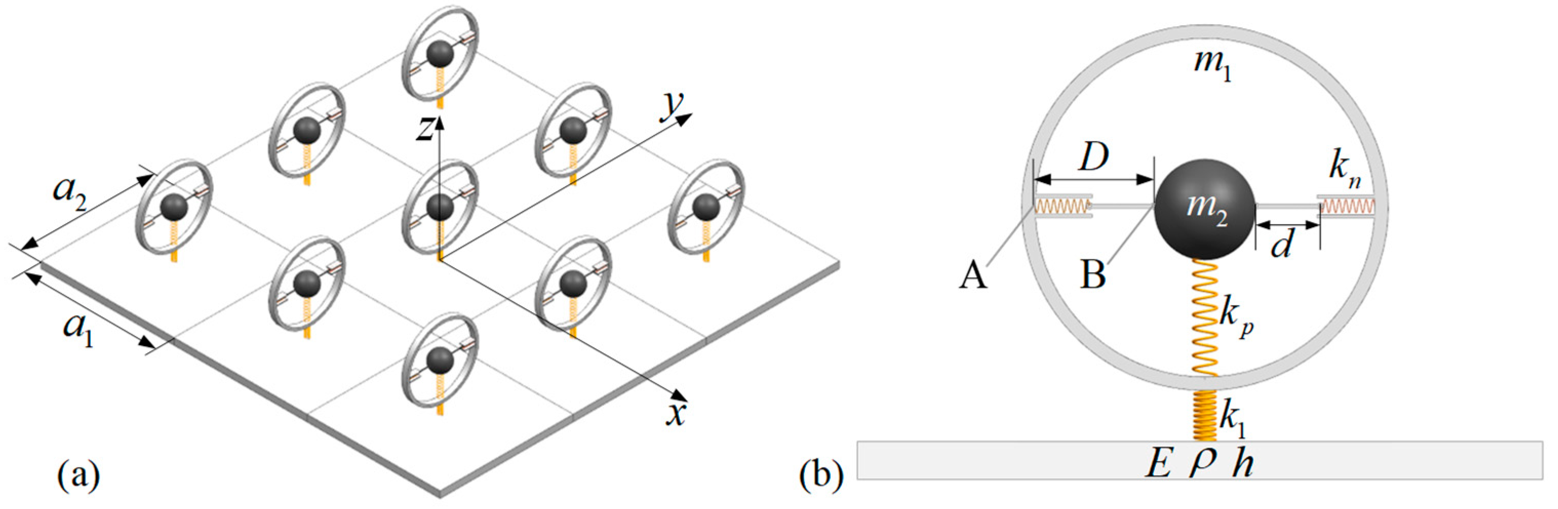
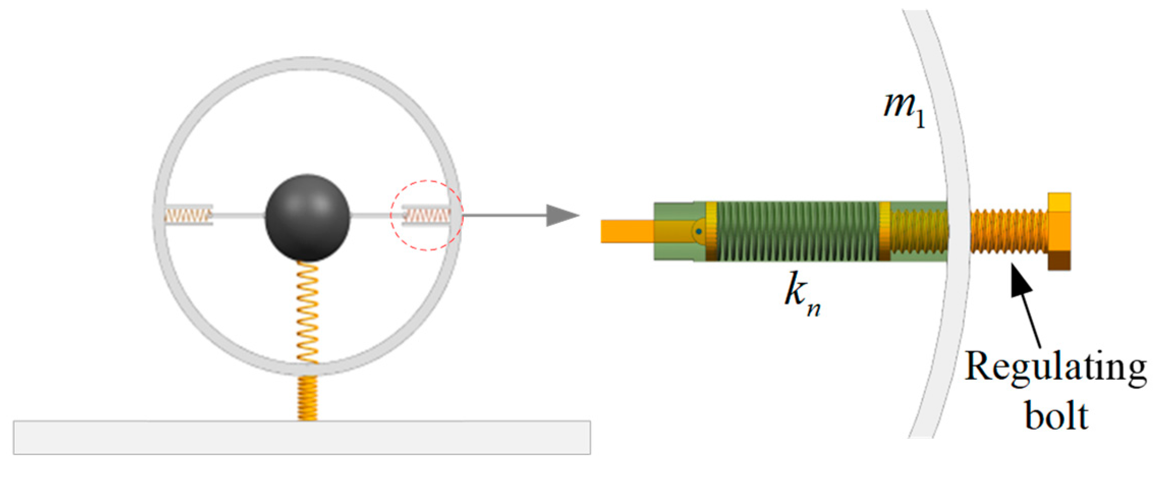
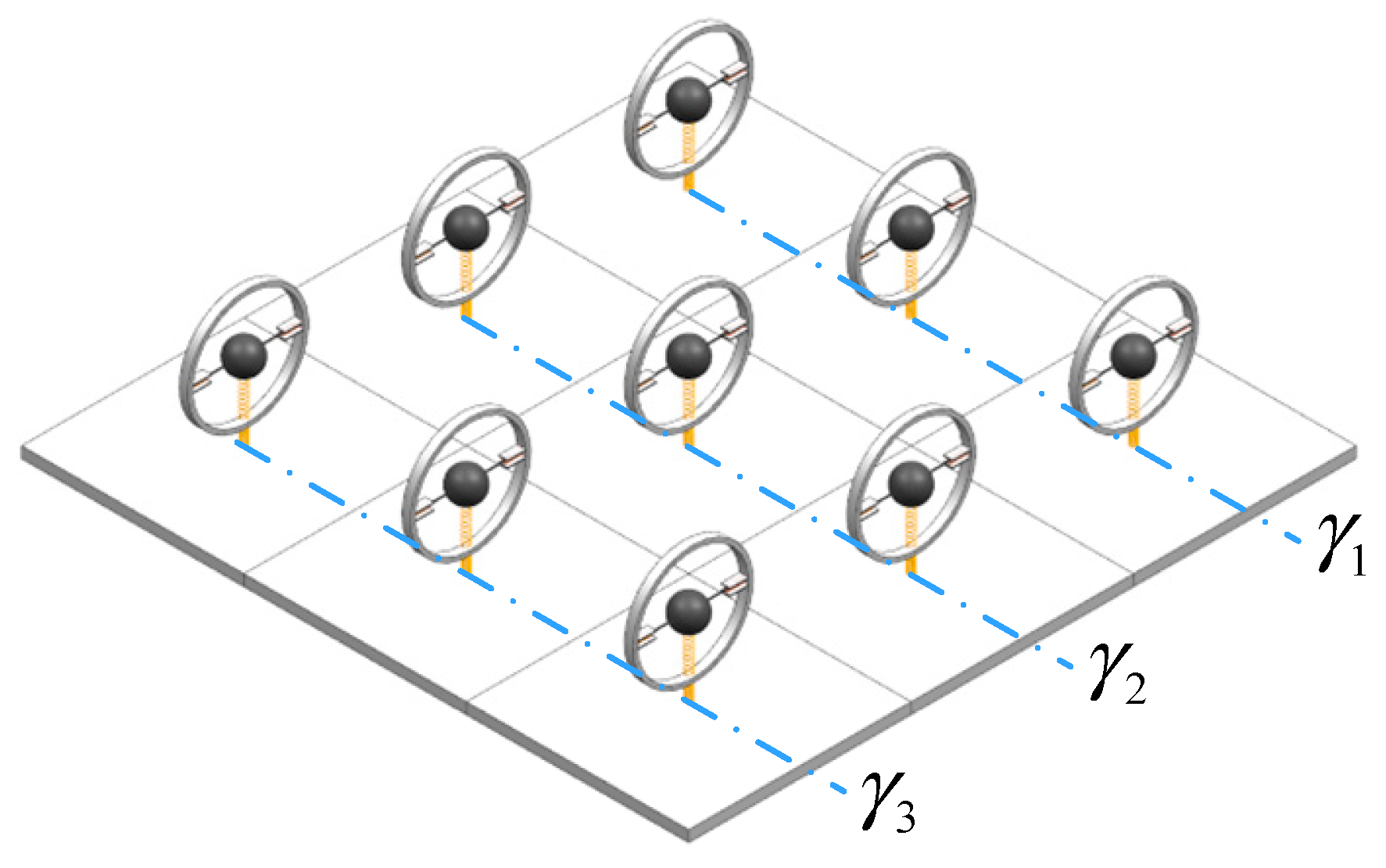
2. Model and Formulations

In this work, an LR plate with two-dimensional periodicity is considered, as shown in Figure 1a. The QZS resonators are periodically attached to a thin plate with spatial period a 1 and a 2 in the xy-plane. The resonator is composed of two masses, a linear spring k 1 , and a QZS system, as shown in Figure 1b. It should be noted that, in the static state, the weight of the mass m 2 is balanced by the tension force of the spring k p . In addition, the mass m 2 is located at the center of the mass m 1 , and the horizontal springs are in a compressed state with a compression of length l c . Additionally, the horizontal spring k n is located within limiting sleeves, limiting it to only expand and contract horizontally. The horizontal spring is connected to the mass m 2 through a rigid rod, which is hinged at both ends. The terms h, E , ρ , and ν denote the plate’s thickness, Young’s modulus, density, and Poisson’s ratio, respectively.
Firstly, the transverse vibration of a unit cell of an infinite periodic LR plate is considered. The governing equations of a unit cell can be written as
D 4 ω 2 ρ h w 0 ( r ) = r k 1 w 1 ( R s ) w 0 ( R s ) δ ( r R s )
ω 2 m 1 w 1 ( R s ) = k 1 w 1 ( R s ) w 0 ( R s ) + k Q w 1 ( R s ) w 2 ( R s ) = 0
and
ω 2 m 2 w 2 ( R s ) = k Q w 2 ( R s ) w 1 ( R s )
where 4 = 2 x 2 + 2 y 2 2 , and D = E h 3 12 ( 1 ν 2 ) is the bending stiffness of the host plate. The term w 0 ( r ) is the displacement of the host plate at coordinate r ( x , y ) . In the expression R s = R + r s , the term R is the position vector of the unit cell and r s is the vector from the center of the unit cell to the resonator. The term w 0 ( R s ) is the displacement of the connection point between the resonator and the plate and w i ( R s ) is the displacement of the mass m i ( i = 1 , 2 ). The term δ r R s is the two-dimensional Dirac delta function. The term k Q is the equivalent stiffness of the QZS system, which can be derived as
k Q = k p 2 k n l c d d 2 ξ 2 3 / 2 d 2 + 1
where ξ is the relative displacement of mass m 1 relative to mass m 2 . Based on the assumption of small displacements, Equation (4) can be approximated by
k Q = k p 2 l c d k n = k p 1 2 γ β
where γ = l c / d represents the initial compression ratio of the spring k n and β = k n / k p is the stiffness ratio of the QZS system.
Following the Bloch’s theorem [31], the displacement response of the plate can be written as
w 0 ( r ) = G W 0 ( G ) e j κ + G r
where κ = ( κ x , κ y ) is the Bloch wave vector. The term G = m b 1 + n b 2 denotes the reciprocal-lattice vector, in which m and n are integers. The terms b 1 and b 2 are basis vectors of the reciprocal lattice. For the rectangular array considered in Figure 1, we have b 1 = 2 π / a 1 , 0 , b 2 = 0 , 2 π / a 2 . Setting m , n = N , , N , then the dimension of the reciprocal space is M × M with M = 2 N + 1 .
Substituting Equation (6) into Equation (1) gives
D 4 ω 2 ρ h G W 0 ( G ) e j κ + G r = R k 1 w 1 ( R s ) w 0 ( R s ) δ ( r R s )
Based on Bloch’s theorem, the terms w 0 R s and w 1 R s can be written as
w 0 ( R s ) = w 0 ( R + r s ) = w 0 ( r s ) e j κ R
and
w 1 ( R s ) = w 1 ( R + r s ) = w 1 ( r s ) e j κ R
Substituting Equations (8) and (9) into Equation (7) gives
D 4 ω 2 ρ h G W 0 ( G ) e j ( κ + G ) r = k 1 w 1 ( r s ) w 0 ( r s ) R e j κ R s δ ( r R s )
It can be given from the properties of the Dirac delta function that
R e j κ R δ ( r R s ) = e j κ ( r r s ) G 1 A e j G ( r r s )
Substituting Equation (11) into Equation (10) yields
G D κ + G 4 ω 2 ρ h W 0 ( G ) e j ( κ + G ) r = G k 1 w 1 ( r s ) w 0 ( r s ) 1 A e j ( κ + G ) ( r s r )
where A = a 1 × a 2 is the area of a unit cell.
Simplifying Equation (12) gives
A D κ + G 4 ω 2 ρ h W 0 ( G ) = k 1 w 1 ( r s ) w 0 ( r s ) e j ( κ + G ) r s
By substituting w 0 ( r s ) = G W 0 ( G ) e j ( κ + G ) r s and w i ( r s ) = w i ( r 0 ) e j κ r s into Equations (1), (3), and (13), it can be obtained that
A D κ + G 4 ω 2 ρ h W 0 ( G ) = k 1 w 1 ( r 0 ) G W 0 ( G ) e j G r s e j G r s
ω 2 m 1 w 1 ( r 0 ) = k 1 w 1 ( r 0 ) w 0 ( r 0 ) + k 2 w 1 ( r 0 ) w 2 ( r 0 )
and
ω 2 m 2 w 2 ( r 0 ) = k Q w 2 ( r 0 ) w 1 ( r 0 )
where r 0 = 0 , 0 , 0 , w 0 ( r 0 ) = G W 0 ( G ) e j κ r s , and Equations (14)–(16) can be expressed by a matrix formulation as
K ω 2 M W = 0
where the matrices K and M and vector W are expressed in detail in Appendix A. The dispersion relationship of the infinite LR plate with QZS resonators can finally be obtained by solving Equation (17).

3. Results and Discussions

In this section, the bandgap characteristics of the QZS LR plate based on the theory in Section 2 are studied in detail. Firstly, the theoretical band structure is compared with the vibration transmittance calculated by the FEM to verify the correctness of the bandgap theory. Next, the effects of stiffness ratio and initial compression ratio on bandgap frequency are discussed. Then, the damping characteristics of the resonators and the differentiated design of bandgaps are further considered to broaden the bandgaps. The parameters of the structure are shown in Table 1.

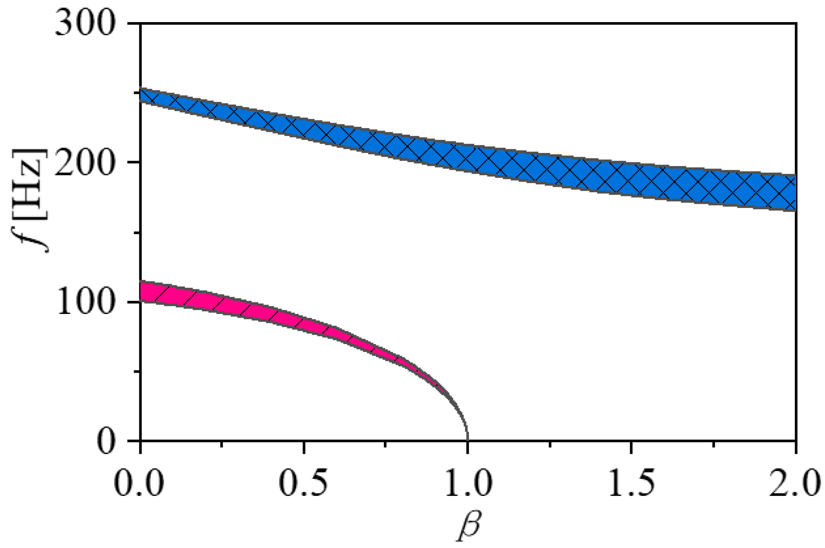
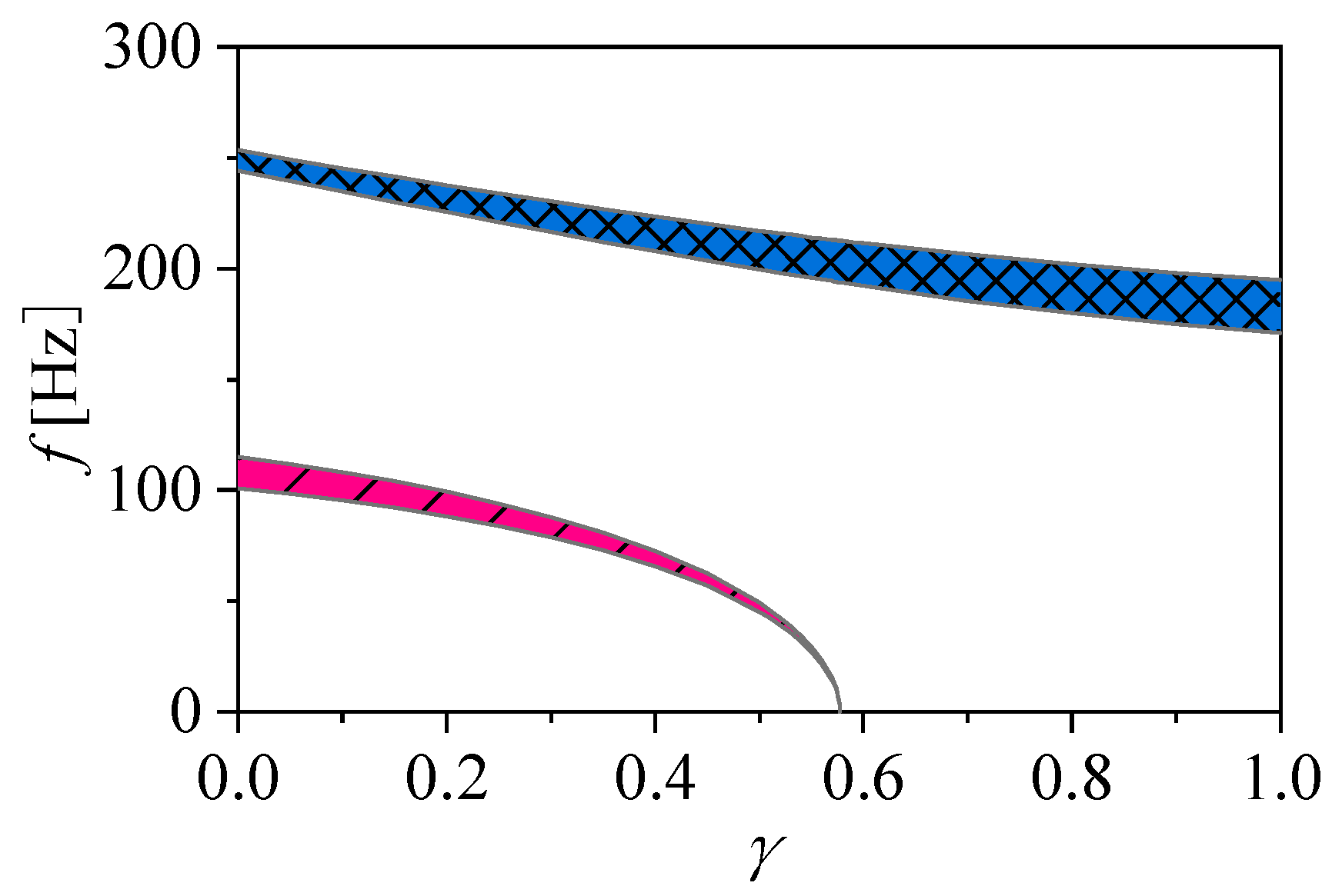
3.1. Band Structure of Infinite Systems

The resonant frequencies of the QZS resonators can be calculated by
f 1 , 2 = 1 4 π k 1 + k Q m 1 + k Q m 2 k 1 m 1 k Q m 2 2 + 2 k Q m 1 k 1 m 1 + k Q m 2 + k Q m 1 2
According to Equation (18) and the parameter settings in Table 1, the resonant frequencies of the QZS resonators are 45 Hz and 200 Hz. The band structures of the LR plate with QZS resonators can be acquired by calculating the dispersion curves in its irreducible region, surrounded by the edges of Γ X , XM , and M Γ . By sweeping the Bloch wave vector κ = ( κ x , κ y ) in Γ X direction ( κ x : 0 π / a 1 , κ y : 0 ), XM direction ( κ x : π / a 1 , κ y : 0 π / a 2 ), and M Γ direction ( κ x : π / a 1 0 , κ y : π / a 2 0 ), the dispersion curves between frequency and wave number are obtained, from which the bandgap can then be identified, as shown in Figure 2a. It can be seen that two bandgaps exist around the two resonant frequencies, i.e., 45–49 Hz and 200–217 Hz, where the first bandgap is generated by the resonance of mass m 2 and the second bandgap is generated by the resonance of mass m 1 .
To verify the correctness of the bandgap theory, a finite plate periodically attached with QZS resonators was modeled by FEM to obtain its vibration transmittance. The FEM model was established with COMSOL Multiphysics software (Version 5.0). For clamped or simply supported boundary conditions, the forced vibration response at the position near the corner points is usually very small, which is inappropriate for assessing the vibration transmittance characteristics of the periodic plate. Therefore, in the simulation model, the four edges of the plate were all set in free boundary conditions.
The size of the finite plate is 1.5   m × 0.8   m × 0.005   m with steel material property. 15 × 8 QZS resonators are periodically distributed on the baseplate with the parameters given in Table 1. The quadratic element type was used in the model. The maximum mesh size is set as 10 mm, which can provide adequate precision for the upper analytical frequency of 300 Hz. In order to simplify the model, the QZS resonator is equivalent to a 2-DOF resonator based on the theory in Section 2, as shown in Figure 3. A transverse point force with a harmonic form is applied at one corner of the plate, represented by the red arrow in the figure. The label “Response” represents the position on the board where the transverse vibration is of interest. Assuming that the acceleration responses of the force point and response point are, respectively, represented by a F and a r , the vibration transmittance can be defined by T L = 20 log 10 a r / a F .
The vibration transmittance of the finite LR plate is drawn in Figure 2b. It can be seen that the theoretically calculated bandgaps coincide with the attenuation frequency bands of vibration response obtained by numerical simulation, which proves the accuracy of the theoretical derivation of the bandgap. In addition, the vibration transmissibility within the bandgap frequency ranges is much smaller than that outside the bandgap, indicating that the propagation of transverse waves is significantly suppressed in the bandgap.
In order to more intuitively observe the vibration transmittance of the baseplate inside and outside the bandgaps, Figure 4 shows the displacement response of the baseplate at certain frequencies. It can be seen that, at the frequency within the bandgaps, the vibration is trapped in a small area near the excitation point. However, as the distance from the excitation point to the observation point increases, the vibration response rapidly decays, as shown in Figure 4a,c, which indicates that the bandgaps generated by QZS resonators can effectively suppress the propagation of transverse waves on the plate. For comparison, at the frequencies outside the bandgaps, the wave freely propagates on the plate without attenuation, as shown in Figure 4b,d.
The advantage of the QZS system is that the dynamic stiffness of the system can be adjusted arbitrarily by changing the system parameters without changing the static stiffness of the system. It can be seen from Equation (5) that, when the positive stiffness k p remains unchanged, the dynamic equivalent stiffness of the system is only determined by the stiffness ratio β and the negative stiffness spring’s initial compression ratio γ . Therefore, the effects of terms β and γ on bandgap characteristics are analyzed in detail in the following.
The effects of the stiffness ratio β on the bandgaps are shown in Figure 5. It can be seen that both of the two bandgaps move towards a lower frequency range as the term β increases. Especially, the first bandgap is quickly transferred to the ultralow frequency range as the term β approaches 1, which suggests that the QZS LR structure proposed in this paper can obtain a low-frequency or even ultralow-frequency bandgap by adjusting the stiffness ratio of the QZS system, so as to suppress the ultralow-frequency transverse waves. It should be noticed that the first bandgap disappears as β 1 . The reason is that the value of equivalent dynamic stiffness k Q becomes negative as β 1 , which results in mass m 2 being unable to resonate. Therefore, the stiffness ratio β of the QZS LR structure needs to be kept below the critical value in a practical application. As β increases, the frequency of the second bandgap shifts towards lower frequencies, and the bandgap width is increased. The ability of the second bandgap to suppress low-frequency vibrations is enhanced, which is a gratifying phenomenon.
In order to further assess the structure’s band-gap characteristics, the first bandgap’s relative band-gap width (RBW) is defined as
R B W = Δ ω ω 2
where Δ ω is the absolute bandwidth of the first bandgap and ω 2 is the resonant frequency of the mass m 2 . The effect of the stiffness ratio β on the first bandgap’s RBW is shown in Figure 6. It can be seen that the RBW decreases slowly with the increase in stiffness ratio β , and it still maintains an appreciable width in the ultralow frequency range, which is different from the sharp change of the absolute bandwidth of the first bandgap shown in Figure 5.
Another important parameter that can adjust the bandgap frequencies is the initial compression ratio γ of the negative stiffness spring. To more clearly figure out the changes, Figure 7 plots the change of the bandgaps for the various γ . In the calculation, the parameter d remains unchanged, and the initial compression ratio γ is adjusted by changing the initial compression l c of the spring k n . As can be seen in Figure 7, the effect of the parameter γ on the bandgaps is similar to that of the parameter β . This phenomenon can be explained by Equation (5), which shows that parameters x and y have a similar effect on the equivalent stiffness of the QZS system. The reason for the disappearance of the first bandgap is the same as that revealed in Figure 5, which will not be repeated here.
The above parametric analysis shows that on the premise of ensuring that the static stiffness of the structure is not weakened and the mass load on the system is not increased, appropriately increasing the stiffness ratio β of the QZS system and the initial compression ratio γ of the negative stiffness spring are effective ways to obtain ultralow-frequency bandgaps.

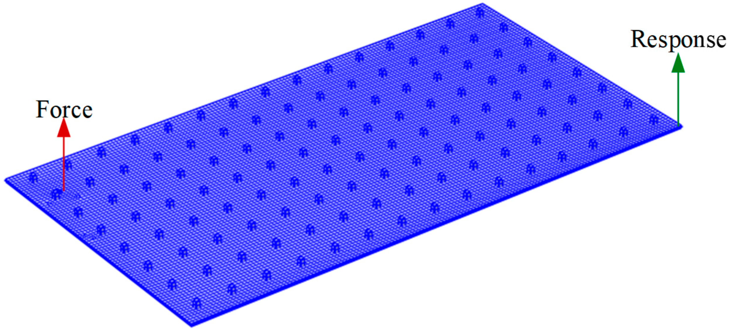
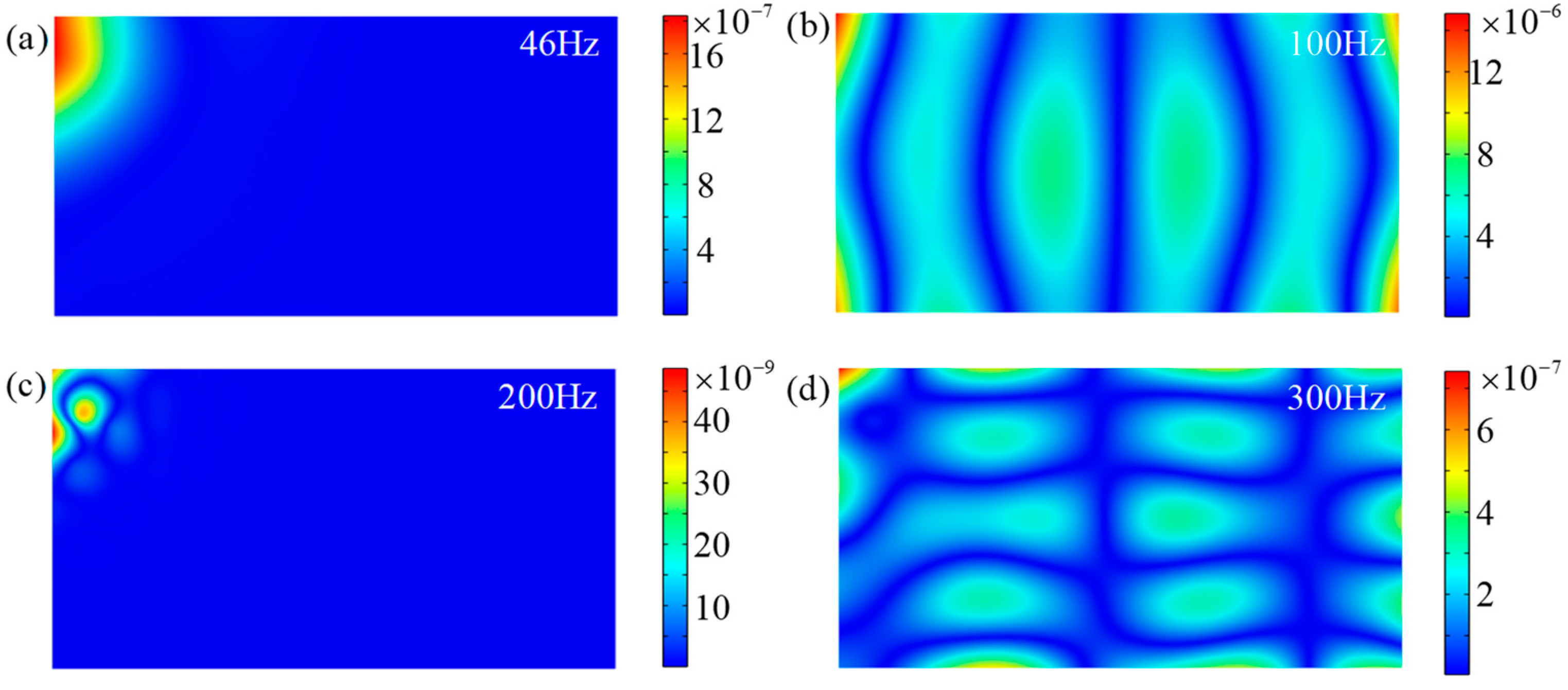
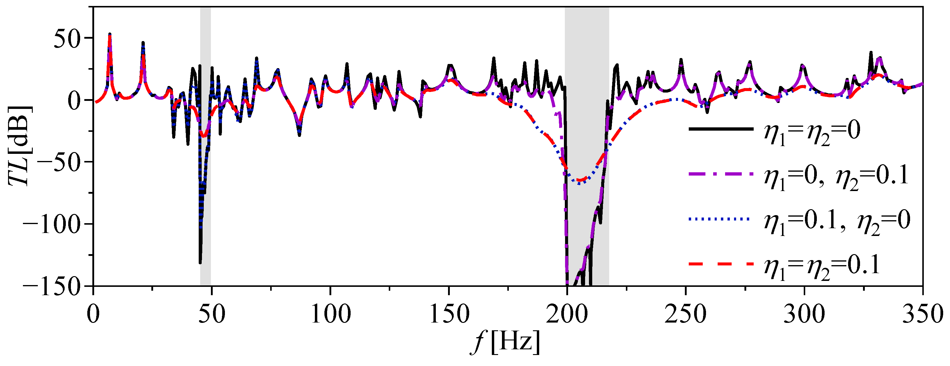
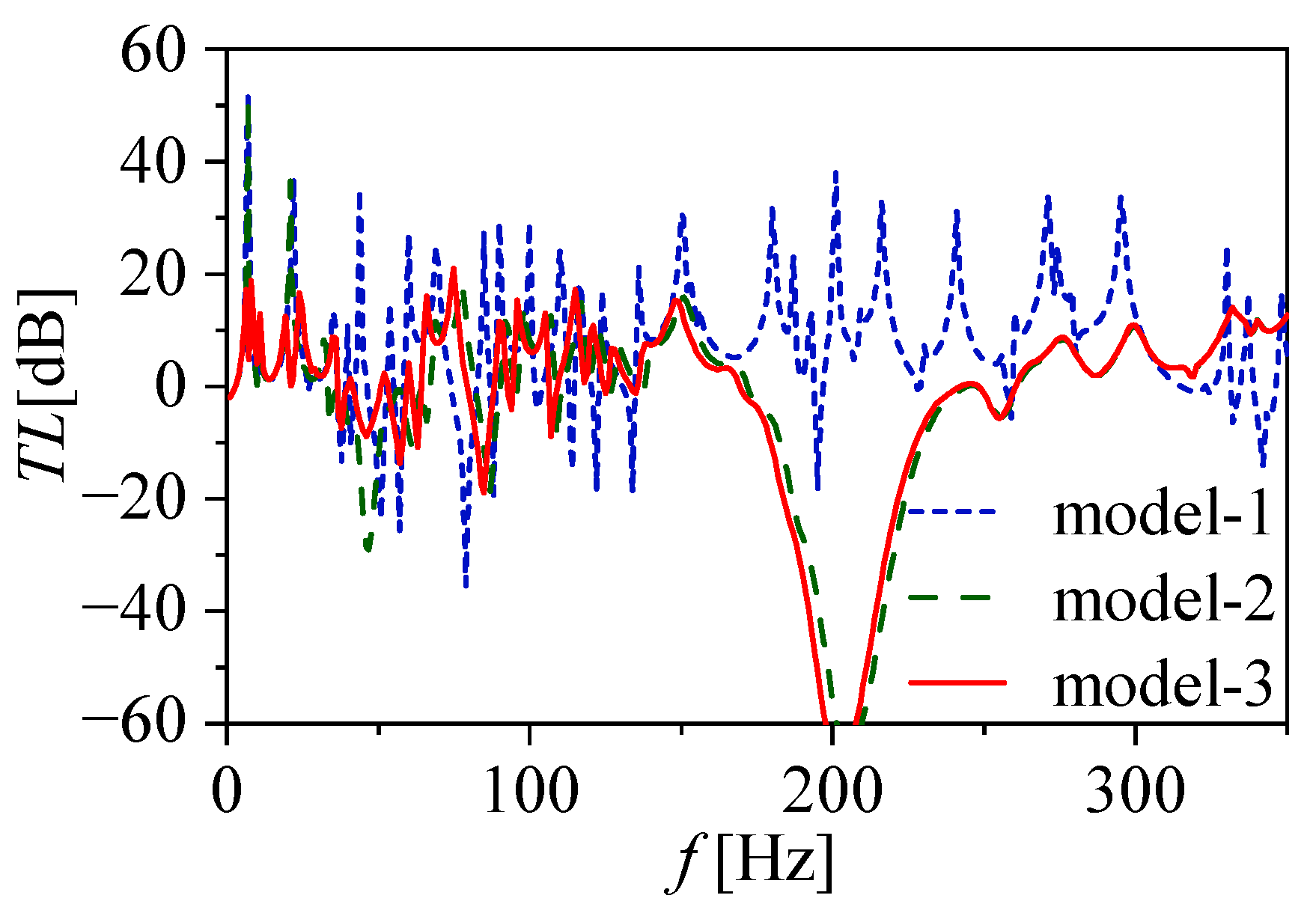
3.2. Vibration Transmittance of Finite Structures

In order to observe the bandgap boundaries more clearly, the damping is not considered in the calculation of the above band structures. As is known to all, damping exists in almost all practical equipment, which has a great effect on wave propagation. Hence, it is necessary to study the effect of damping in the QZS resonators on bandgap characteristics. The vibration transmittance of the finite LR plate with varying damping loss factors is shown in Figure 8. The parameter settings in the calculation are the same as those in Table 1. The terms η 1 and η 2 represent the damping loss factors of spring k 1 and spring k p , respectively.
As can be seen from Figure 8, with η 2 kept as zero and η 1 varying from 0 (black solid line) to 0.1 (blue short dot line), the range of the attenuation band near the second bandgap becomes broader while the depth becomes shallower, and the first bandgap changes little. The effect of the damping loss factor η 2 on the bandgaps is somewhat different from that of the damping loss factor η 1 . As η 2 increases from 0 (black solid line) to 0.1 (green dash-dot line), the range of the attenuation band near the first bandgap is widened, and the high vibration transmittance near the second bandgap is also effectively suppressed. The reason for this phenomenon is that the effect of η 1 is only related to the displacement of mass m 1 , while the effect of η 2 is related to both displacements of mass m 1 and mass m 2 . Therefore, changing the damping loss factor η 2 can affect both bandgaps at the same time. Of course, a better bandgap widening performance can be obtained by increasing the factors η 1 and η 2 at the same time.
In Figure 8, there are still two obvious ultralow-frequency vibration transmittance peaks with frequencies of 7 Hz and 21 Hz, which are undesirable in vibration control. For the traditional resonant structure, it is usually difficult to change its resonance frequency after the structure is finalized. In addition, for low-frequency or even ultralow-frequency vibration control, the mass of the corresponding resonator must be ultra-large, or the static stiffness of the spring must be ultra-small, which is often not allowed in practice. Therefore, it is still difficult for traditional resonators to have both flexible bandgap adjustability and low-frequency bandgap performance. It can be seen from Figure 7 that the bandgaps of the QZS resonator proposed in this paper can be flexibly adjusted to the ultralow frequency range by changing the initial compression of the spring k n without increasing the mass load. Based on this characteristic, two additional ultralow frequency bandgaps can be generated by adjusting the initial compression of part resonators of the periodic array so as to suppress the two ultralow frequency resonance peaks.
In order to adjust parameter l c conveniently during use, a distance-adjusting device is designed, as shown in Figure 9. Under the premise that the system parameters are unchanged, the initial compression of the negative stiffness spring k n can be easily changed by rotating the adjusting screw so as to achieve the purpose of adjusting the bandgap frequencies. In order to further obtain two additional low-frequency bandgaps on the basis of Figure 8, the strategy adopted here is to use the structure shown in Figure 9 to differentially design the bandgaps of the QZS LR structure.
The QZS resonators with different bandgaps are alternately periodically distributed on the baseplate, as shown in Figure 10. In order to suppress the high vibration response at the frequencies of 7 Hz and 21 Hz in Figure 8, we set the parameters γ 1 = 0.5 , γ 2 = 0.561 , and γ 3 = 0.576 according to Equations (5) and (18). The other parameters are consistent with those of the calculation model corresponding to Figure 8.
The comparison of vibration transmittances with different resonator arrays attached to the plate is shown in Figure 11. In the figure, model-2 represents the calculation model corresponding to Figure 8 with damping loss factors η 1 = η 2 = 0.1 , and model-3 is the system shown in Figure 10 with damping loss factors η 1 = η 2 = 0.1 . For comparison purposes, a plate with the same mass load as the QZS LR plate, named model-1, was also constructed. As can be seen from Figure 11, compared with model-1, the TL of model-2 has two obvious bandgaps around 45 Hz and 200 Hz, while model-3 not only exhibits two vibration transmittance attenuation bands near the above two frequencies but also exhibits two additional vibration attenuation bands around 7 Hz and 21 Hz. The vibration transmittances at 7 Hz and 21 Hz are reduced by 32 dB and 20 dB, respectively. The main vibration modes below 70 Hz are effectively controlled by the differentiated design of the bandgaps without adding additional mass load, which proves that the QZS resonator has broadband ultralow-frequency vibration suppression performance.

4. Conclusions

A locally resonant (LR) plate with attached quasi-zero-stiffness (QZS) resonators is investigated in this study. The design of the QZS resonator is a unique blend of a mass-in-mass resonator and a QZS system tailored for the attenuation of ultralow-frequency vibrations. The QZS resonator is designed by combining a mass-in-mass resonator and a QZS system to meet the demand for ultralow-frequency vibration attenuation. The plane wave expansion method is employed to derive the band structure of the LR plate. The result shows that the LR plate with QZS resonators exhibits two bandgaps, and the ranges of the bandgaps agree well with the vibration attenuation bands calculated by the finite element method.
The stiffness ratio and initial compression of the negative stiffness spring are taken into consideration to evaluate the effects on the bandgaps by parameter analyses. The parameter variable trends show that increasing the stiffness ratio and the initial compression of negative stiffness spring can lower the frequencies of the bandgaps, thereby obtaining low-frequency or even ultralow-frequency bandgaps. The effect of damping is also studied, and the result shows that the damping from the resonator spring can broaden the vibration attenuation band.
Inspired by the discoveries of varying bandgap trends with changes in the negative stiffness spring’s initial compression, a distance-adjusting device is introduced. This device can provide a versatile solution for tuning bandgap frequencies on demand. This innovation eliminates the need for additional mass loads and can significantly enhance the QZS resonator’s engineering practicality.
The QZS resonators designed in this paper have the application prospect of suppressing broadband low-frequency transverse waves of plate-type structures.

Author Contributions

Conceptualization, Z.G. and B.X.; methodology, Z.G. and B.X.; software, B.X.; validation, Z.G.; formal analysis, B.X.; investigation, Z.G.; resources, M.S.; data curation, H.Z.; writing—original draft preparation, B.X. and Z.G.; writing—review and editing, M.S. and H.Z.; visualization, B.X. and Z.G.; supervision, M.S.; project administration, M.S.; funding acquisition, Z.G. and M.S. All authors have read and agreed to the published version of the manuscript.

Funding

This research was funded by the National Natural Science Foundation of China (grant number 52301388), the Natural Science Foundation of Ningbo City, China (grant number 2021J057), and the Natural Science Foundation of Shaanxi Province, China (grant number 2021JLM-39).

Institutional Review Board Statement

Not applicable.

Informed Consent Statement

Not applicable.

Data Availability Statement

The original contributions presented in the study are included in the article, further inquiries can be directed to the corresponding author.

Conflicts of Interest

The authors declared no potential conflicts of interest with respect to the research, authorship, and/or publication of this article.

Appendix A

The matrix K in Equation (17) is expressed as
K = A D K 11 + k 1 U 1 U 2 k 1 U 1 0 k 1 U 2 k 1 + k 2 k 2 0 k 2 k 2
where U 1 = e j G 1 r s e j G 2 r s e j G M ¯ r s T , U 2 = e j G 1 r s e j G 2 r s e j G M ¯ r s T , and K 11 is given as
K 11 = κ + G 1 4 κ + G 2 4 κ + G M ¯ 4
The matrix M in Equation (17) is expressed as
M = A ρ h [ I ] M m 1 m 2
The matrix W in Equation (17) is expressed as
W = W 0 ( G ) w 1 ( r 0 ) w 2 ( r 0 )

References

  1. Putra, A.; Thompson, D.J. Sound radiation from rectangular baffled and unbaffled plates. Appl. Acoust. 2010, 71, 1113–1125. [Google Scholar] [CrossRef]
  2. Li, B.; Wang, N.; Tian, Y.; Kuang, W.; Wei, L.; Zheng, Z. Analysis of vibration and acoustic radiation characteristics of reinforced laminated cylindrical shell structure. Appl. Sci. 2023, 13, 9617. [Google Scholar] [CrossRef]
  3. Kerwin, E.M. Comparison of the vibration damping effectiveness of free and constrained viscoelastic layers. J. Acoust. Soc. Am. 2005, 31, 1852–1856. [Google Scholar] [CrossRef]
  4. Lei, Y.; Adhikari, S.; Friswell, M.I. Vibration of nonlocal Kelvin–Voigt viscoelastic damped Timoshenko beams. Int. J. Eng. Sci. 2013, 66–67, 1–13. [Google Scholar] [CrossRef]
  5. Wong, W.O.; Tang, S.L.; Cheung, Y.L.; Cheng, L. Design of a dynamic vibration absorber for vibration isolation of beams under point or distributed loading. J. Sound Vib. 2007, 301, 898–908. [Google Scholar] [CrossRef]
  6. Yang, C.; Li, D.; Cheng, L. Dynamic vibration absorbers for vibration control within a frequency band. J. Sound Vib. 2011, 330, 1582–1598. [Google Scholar] [CrossRef]
  7. Teo, Y.R.; Fleming, A.J. Optimal integral force feedback for active vibration control. J. Sound Vib. 2015, 356, 20–33. [Google Scholar] [CrossRef]
  8. Wang, L.; Li, J.; Yang, Y.; Wang, J.; Yuan, J. Active control of low-frequency vibrations in ultra-precision machining with blended infinite and zero stiffness. Int. J. Mach. Tools Manuf. 2019, 139, 64–74. [Google Scholar] [CrossRef]
  9. Xie, X.; Ren, M.; Zheng, H.; Zhang, Z. Active vibration control of a time-varying shafting system using an adaptive algorithm with online auxiliary filter estimation. J. Sound Vib. 2021, 513, 116430. [Google Scholar] [CrossRef]
  10. Torrent, D.; Mayou, D.; Sánchez-Dehesa, J. Elastic analog of graphene: Dirac cones and edge states for flexural waves in thin plates. Phys. Rev. B 2013, 87, 269–275. [Google Scholar] [CrossRef]
  11. Sun, H.; Du, X.; Pai, P.F. Theory of metamaterial beams for broadband vibration absorption. J. Intell. Mater. Syst. Struct. 2010, 21, 1085–1101. [Google Scholar] [CrossRef]
  12. Pai, P.F.; Peng, H.; Jiang, S. Acoustic metamaterial beams based on multi-frequency vibration absorbers. Int. J. Mech. Sci. 2014, 79, 195–205. [Google Scholar] [CrossRef]
  13. Peng, H.; Frank Pai, P. Acoustic metamaterial plates for elastic wave absorption and structural vibration suppression. Int. J. Mech. Sci. 2014, 89, 350–361. [Google Scholar] [CrossRef]
  14. Nouh, M.; Aldraihem, O.; Baz, A. Wave propagation in metamaterial plates with periodic local resonances. J. Sound Vib. 2015, 341, 53–73. [Google Scholar] [CrossRef]
  15. Gulia, P.; Gupta, A. Sound attenuation in triple panel using locally resonant sonic crystal and porous material. Appl. Acoust. 2019, 156, 113–119. [Google Scholar] [CrossRef]
  16. Qian, D.; Shi, Z. Bandgap properties in simplified model of composite locally resonant phononic crystal plate. Phys. Lett. A 2017, 381, 3505–3513. [Google Scholar] [CrossRef]
  17. Liu, H.; Shi, Z.; Wang, Y.; Zhai, H. A band gap optimization scheme for two-dimensional locally resonant phononic crystal with square spiral rings. Phys. Lett. A 2022, 442, 128134. [Google Scholar] [CrossRef]
  18. Badreddine Assouar, M.; Sun, J.H.; Lin, F.S.; Hsu, J.C. Hybrid phononic crystal plates for lowering and widening acoustic band gaps. Ultrasonics 2014, 54, 2159–2164. [Google Scholar] [CrossRef]
  19. Li, Y.; Chen, T.; Wang, X.; Xi, Y.; Liang, Q. Enlargement of locally resonant sonic band gap by using composite plate-type acoustic metamaterial. Phys. Lett. A 2015, 379, 412–416. [Google Scholar] [CrossRef]
  20. Wang, T.; Sheng, M.; Guo, Z.; Qin, Q. Flexural wave suppression by an acoustic metamaterial plate. Appl. Acoust. 2016, 114, 118–124. [Google Scholar] [CrossRef]
  21. Fan, X.; Li, J.; Zhang, X.; Li, F. Multi-bandgaps metamaterial plate design using complex mass-beam resonator. Int. J. Mech. Sci. 2022, 236, 107742. [Google Scholar] [CrossRef]
  22. Van Belle, L.; Claeys, C.; Deckers, E.; Desmet, W. The impact of damping on the sound transmission loss of locally resonant metamaterial plates. J. Sound Vib. 2019, 461, 114909. [Google Scholar] [CrossRef]
  23. Carrella, A.; Brennan, M.J.; Kovacic, I.; Waters, T.P. On the force transmissibility of a vibration isolator with quasi-zero-stiffness. J. Sound Vib. 2009, 322, 707–717. [Google Scholar] [CrossRef]
  24. Zhao, F.; Ji, J.C.; Ye, K.; Luo, Q. Increase of quasi-zero stiffness region using two pairs of oblique springs. Mech. Syst. Signal Process. 2020, 144, 106975. [Google Scholar] [CrossRef]
  25. Liu, C.; Zhao, R.; Yu, K.; Liao, B. In-plane quasi-zero-stiffness vibration isolator using magnetic interaction and cables: Theoretical and experimental study. Appl. Math. Model. 2021, 96, 497–522. [Google Scholar] [CrossRef]
  26. Li, M.; Li, Y.; Liu, X.; Dai, F. A quasi-zero-stiffness vibration isolator using bi-stable hybrid symmetric laminate. Compos. Struct. 2022, 299, 116047. [Google Scholar] [CrossRef]
  27. Zhang, Y.; Cao, Q. The recent advances for an archetypal smooth and discontinuous oscillator. Int. J. Mech. Sci. 2022, 214, 106904. [Google Scholar] [CrossRef]
  28. Xie, B.; Sheng, M. Ultralow-frequency band gap in a quasi-zero-stiffness multi-resonator periodic hybrid structure. Wave Motion 2021, 107, 102825. [Google Scholar] [CrossRef]
  29. Huang, H.H.; Sun, C.T. Wave attenuation mechanism in an acoustic metamaterial with negative effective mass density. New J. Phys. 2009, 11, 013003. [Google Scholar] [CrossRef]
  30. Wang, K.; Zhou, J.; Ouyang, H.; Cheng, L.; Xu, D. A semi-active metamaterial beam with electromagnetic quasi-zero-stiffness resonators for ultralow-frequency band gap tuning. Int. J. Mech. Sci. 2020, 176, 105548. [Google Scholar] [CrossRef]
  31. Brillouin, L. Wave Propagation in Periodic Structures; Dover Publication: New York, NY, USA, 1953; pp. 17–18. [Google Scholar]
Figure 1. The schematic view of (a) the LR plate and (b) the unit cell containing the QZS resonator.
Applsci 14 01467 g001
Figure 2. Comparison of (a) the band structure of the LR plate with QZS resonators and (b) the vibration transmittance computed by FEM.
Applsci 14 01467 g002
Figure 3. Finite element model of the finite LR plate.
Applsci 14 01467 g003
Figure 4. The displacement responses of the finite baseplate with QZS resonators at the frequencies within bandgaps: (a) 46 Hz and (c) 200 Hz; and outside bandgaps: (b) 100 Hz and (d) 300 Hz.
Applsci 14 01467 g004
Figure 5. Effects of the stiffness ratio β on the bandgaps.
Applsci 14 01467 g005
Figure 6. Effect of the stiffness ratio β on the RBW of the first bandgap.
Applsci 14 01467 g006
Figure 7. Effects of the initial compression ratio γ of the negative stiffness spring on the bandgaps.
Applsci 14 01467 g007
Figure 8. Effects of damping on vibration transmittance of the finite LR plate.
Applsci 14 01467 g008
Figure 9. Schematic of the initial compression regulator of spring k n .
Applsci 14 01467 g009
Figure 10. Schematic diagram of a finite LR plate with multiple periodic arrays of attached QZS resonators.
Applsci 14 01467 g010
Figure 11. Vibration transmittance comparison of various resonator arrays attached to the plate.
Applsci 14 01467 g011
Table 1. Parameters of the QZS LR plate.
Plate ParametersQZS Resonator Parameters
Density ρ = 7850   kg / m 3 Mass 1 m 1 = 78.5   g
Young’s modulus E = 216   GPa Mass 2 m 2 = 78.5   g
Poisson’s ratio ν = 0.28 Spring stiffness k 1 k 1 = 1.17 × 10 5   N / m
Plate thickness h = 5   mm Spring stiffness k p k p = 5 × 10 4   N / m
Lattice constant a 1 = a 2 = 0.1   m Spring stiffness k n k n = 4.33 × 10 4   N / m
Compression ratio γ = 0.5
Disclaimer/Publisher’s Note: The statements, opinions and data contained in all publications are solely those of the individual author(s) and contributor(s) and not of MDPI and/or the editor(s). MDPI and/or the editor(s) disclaim responsibility for any injury to people or property resulting from any ideas, methods, instructions or products referred to in the content.

