Abstract
In this paper, we propose Automatic Configuration Memory Fault Injection (ACMFI), a tool that calculates the architectural vulnerability factor (AVF) and soft error rate (SER) using the emulation fault injection technique. SER, which is essential for the safety design of aerospace electronics, can be obtained by experiments (beam tests) performed in a beam facility equipped with high-energy radiation facilities. However, SER calculation using beam tests has the disadvantage of a high cost and a long waiting time, making it difficult to use in the conceptual design stage, which is the aerospace system development stage and the initial HW/SW development stage. Using the emulation fault injection method, it is possible to estimate the SER, which can be used in the system safety design phase. This paper describes the ACMFI tool, which automatically performs emulation fault injection in SRAM-based FPGAs, which are widely used in aerospace electronic hardware. Unlike the existing methods, the proposed method has the advantage of minimizing the side effects by injecting faults into a dedicated SRAM area. In other words, the SER obtained by the proposed method can be estimated more accurately than the SER result obtained by the existing method. To prove the accuracy of the proposed test method, the SER calculated by performing an emulation fault injection test on the same FPGA was compared with the SER results tested at the beam facility. The method of obtaining SER using the proposed ACMFI gave results that were closer to the SER obtained by testing at the beam facility than the method of obtaining SER using the existing EMFI. The proposed method is used to calculate the failure rate, which is a key variable in determining the development assurance level when performing safety design tests in aerospace system development, enabling the development of safer systems and lower cost/higher quality aerospace electronic equipment than before.
1. Introduction
The reliability of aerospace electronic equipment is increasingly crucial as its role in various applications expands. With advancements in semiconductor processing technology, the prevalence of both permanent and temporary faults, including transient and permanent errors, has risen significantly [1,2]. This issue is particularly acute for electronic equipment operating in space, where exposure to various types of radiation is a major concern. Failures in electronic equipment due to radiation are primarily classified into the following two types: total ionizing dose (TID) and single-event effect (SEE) failures [3]. While regular replacement cycles can mitigate the hard errors caused by TID, soft errors resulting from SEE are random and temporary, rendering them unresolvable through replacement cycles alone. Consequently, evaluating the impact of soft errors in advance becomes crucial. The soft error rate (SER) is a key metric used to assess the likelihood of soft errors occurring per hour [4].
The most direct and traditional method of calculating SER is testing at a radiation facility [5,6,7]. These methods evaluate the soft error of a board by exposing it to ionized particles using a particle accelerator. This is called the Hardware Fault Injection Approach and is mainly divided into ion and laser methods, depending on the type of particle. The Hardware Fault Injection Approach provides benefits in terms of speed, low complexity, and the ability to perform accurate SER evaluations from a system perspective. However, there are also challenges associated with this evaluation method, such as its high cost, the inability to reproduce test results, and difficulties in conducting a detailed analysis, such as fault propagation analysis.
To reduce the issue of high radiation test costs, various approaches to simulation fault injection are being studied. The software fault injection method evaluates the soft error rate (SER) by implementing a fault model in a circuit simulator, such as TCAD or SPICE, at the Verilog/VHDL RTL level [8,9]. The methods are low-cost and can provide more accurate sensitivity analysis because they can calculate both the defect injection rate and the injection location. However, recent System-on-Chip (SoC) level components have high circuit complexity, which increases the analysis time and complexity.
To address the limitations inherent in hardware and software approaches, the development of emulation-based fault injection tools is underway. This method entails the artificial simulation of single-event upsets (SEUs) on the actual target board [10,11,12]. Emulation fault injection offers results that are comparable to hardware methods, while also providing the cost efficiency and test reusability commonly associated with software methods. Nonetheless, this approach presents its own set of challenges, including the need to establish an emulation testing environment, the requirement of a comprehensive understanding of the target board, and complexities in implementation.
To overcome these challenges, more user-friendly and accessible emulation-based fault injection tools are under development [13,14]. These tools are designed to enable fault injection testing across a wide variety of FPGA configuration memories. However, the extensive range of this fault injection testing method may introduce difficulties in analyzing the failures that specifically reflect the characteristics of the target circuit.
In this study, we developed an Automatic Configuration Memory Fault Injection (ACMFI) tool to estimate the SER of an avionics board. The tool injects a bit-flip error into the configuration memory of an SRAM-based FPGA board. The ACMFI tool optimizes the fault injection process in FPGAs and allows for the easy creation of a test environment by utilizing an open library (SEM IP) without the need to modify the target circuit. The ACMFI tool assists users in conducting fault injection simulations by allowing them to select the target area for fault injection and automatically generating statistical fault injection test scenarios.
The tool offers several advantages. Firstly, it effectively addresses the side effect problem by restricting the fault injection to specific, predefined areas within the device under test (DUT). This method ensures that the faults are contained within their designated regions and do not introduce unnecessary errors into other external areas designated for fault injection. Additionally, as an API-based fault injection tool, it facilitates the swift creation and update of test environments. These advantages enhance the accessibility of the testing process and support user-friendly testing. Furthermore, it allows for an accurate analysis without requiring modifications or additions to the testing circuit.
The soft error rate (SER) of four types of security circuits was analyzed using Digilent’s Zybo-Z7 20 board as a case study of the ACMFI tool. The security circuits analyzed were as follows: the Data Encryption Standard (DES); Advanced Encryption Standard (AES); Secure Hash Algorithm (SHA); and Ron Rivest, Adi Shamir, and Leonard Adleman (RSA). For statistical fault injection testing, ATALANTA, an open-source Automatic Test Pattern Generator (ATPG) tool [15], was utilized. A literature review was also conducted to gather the necessary data for calculating the .
A linear relationship analysis was carried out to analyze the AVF and SER results presented in this study. Through this linear correlation analysis, side effect minimization was proposed, highlighting a strong coefficient of determination for DUT-coverage AVF. In addition, exponential distribution reliability modeling was applied to evaluate system-level reliability in terms of the soft error rate (SER). To compare the reliability assessments, different emulation and beam test results were applied to the reliability model and compared. The results confirmed that the ACMFI tool alleviated the problem of reliability overestimation due to the existing side effects and provided estimates similar to the beam test results.
The document is structured as follows: Section 2 explains the failures caused by the radiation effects in SRAM-based FPGAs and various methodologies to analyze them. Section 3 describes the ACMFI tool developed in this paper, including the statistical fault injection test procedure and SER estimation method. In Section 4, the proposed tool is used to analyze and discuss the vulnerability and reliability of four types of target security circuits. Finally, Section 5 provides a summary of the conclusions reached in this paper.
2. Background
Section 2 explains the effects of radiation on field-programmable gate arrays (FPGAs) and the previous studies analyzing them. This section begins with an introduction to the effects of radiation on FPGA technology, emphasizing the importance of understanding these effects for robust system design (Section 2.1). This is followed by a discussion of the impact of single-event upsets (SEUs) in SRAM-based FPGAs on these devices (Section 2.2). Additionally, various fault injection methods used for SEU analysis are explained, including hardware, software, simulation, and emulation approaches (Section 2.3). Finally, we present a detailed description of the existing emulation-based fault injection methods and the issues to be examined (Section 2.4).
2.1. Radiation Effect
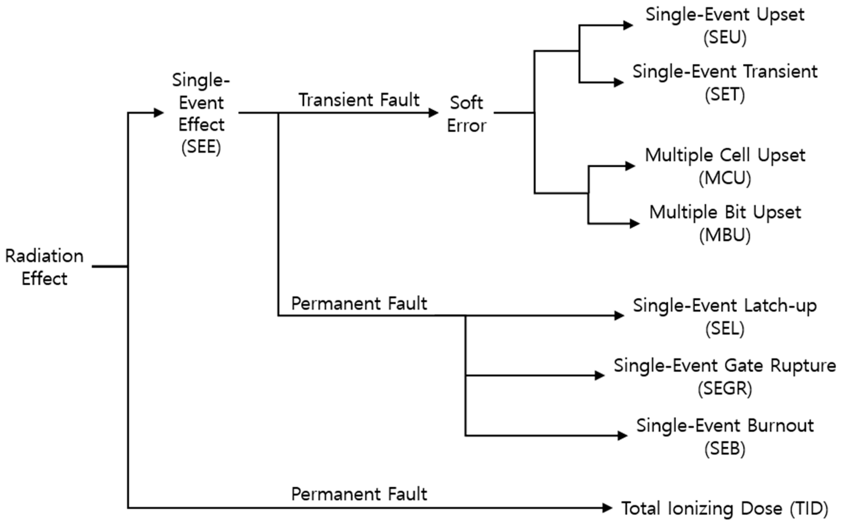
Circuits operating in the space environment may experience unexpected faults due to the interaction between ionized particles (neutrons, etc.) caused by space radiation and the internal IC chip [1,2]. Figure 1 summarizes the effects on FPGA that can be caused by space radiation. When the ionized particles generated by the activities of celestial bodies, such as the sun or stars in space, radiate electronic devices, they affect the charge of the internal transistors and disturb their states. Depending on the location and amount of charge transferred by collision of particles, temporary or permanent effects may occur at this time.
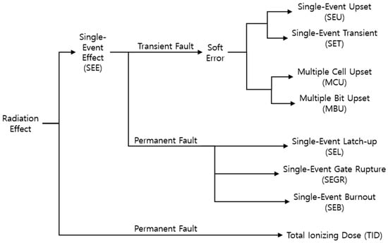
Figure 1.
Radiation effects on FPGA.
The effects caused by single-event interactions are called single-event effects (SEEs), and they can be either temporary or permanent [3]. If SEEs exhibit transient characteristics, they are referred to as a soft error, as they do not result in permanent damage to the device. Examples of these soft errors are classified as single-event upsets (SEU) and single-event transient (SET), depending on the location of their influence, as follows: (1) SEU is the effect of a bit flip that occurs when an ionized particle strikes the transistor of a memory cell and transfers enough charge to invert the state of the memory cell. The memory cell still performs write or read operations normally, but the stored information is damaged. (2) SET is a phenomenon that occurs when ionized particles strike a logic cell.
When a single-event effect (SEE) of two bits or more occurs in a memory cell, it is classified into multiple-cell upset (MCU) or multiple-bit upset (MBU), depending on whether it occurs within one word of the memory cell. For example, if a SEE of two bits or more occurs in a memory cell within the same word, it is called an MBU, while if a SEE of two bits or more occurs simultaneously in different words, it is called an MCU. If a SEE occurs permanently, it may be caused by single-event latch-up (SEL), single-event gate rupture (SEGR), or single-event burnout (SEB).
When an FPGA is exposed to ionized particles for an extended period, an effect called total ionizing dose (TID) occurs due to the accumulation of particle interactions. TID reduces the transistor performance by altering the threshold voltage and leakage current. Unlike the single-event effect (SEEs) described earlier, this phenomenon cannot be mitigated through correction methods involving reset or reloading, as the characteristics of the IC have permanently changed.
2.2. Single-Event Upsets on SRAM-Based FPGAs
Field-programmable gate arrays (FPGAs) are configurable integrated circuits based on high-density logic structures that can be customized by end users to implement a variety of designs. FPGA architecture is built upon customizable logic block arrangements and connections via logic blocks and programmable switches. Among these, SRAM (synchronous random-access memory)-based FPGAs are most commonly used. SRAM-based FPGAs utilize programmable switches implemented as pass transistors or multiplexers controlled according to the SRAM bit status.
SRAM-based FPGAs consist of a configuration logic block (CLB), routing, Block RAM, digital signal processing (DSP), and a set of control and management logic. The CLB comprises a look-up table (LUT) that implements combinational logic and a flip-flop (DFF) that implements sequential elements. The routing architecture is highly complex, consisting of millions of predefined wires, allowing the construction of desired routing using multiplexers and switches.
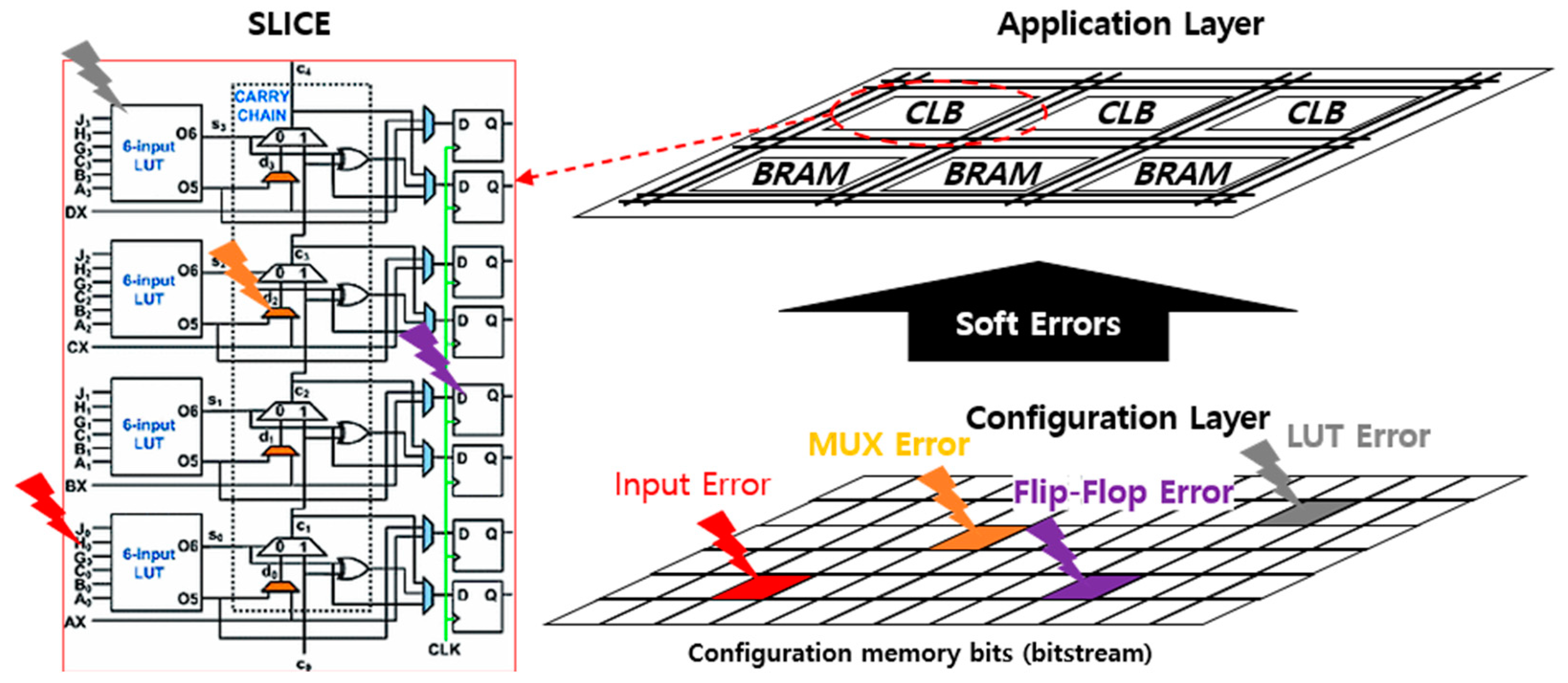
The configuration of all CLBs, routing, Block RAM, DSP blocks, and IO blocks is performed using a set of configuration memory bits known as the bitstream. Depending on the FPGA device’s size, the bitstream can contain millions of bits. The memory bits that store the bitstream inside of the FPGA are composed of SRAM memory cells and are, therefore, reprogrammable and volatile. As shown in Figure 2, tthis bit flip can occur when a single-event effect (SEE) affects the configuration memory bits of an SRAM-based FPGA. This bit flip can alter the configuration of a routing connection or a CLB’s LUT or flip-flop. Such alterations can have a detrimental impact on the designed circuit, potentially leading to changes in the circuit’s function due to SEE.
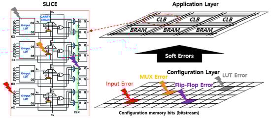
Figure 2.
Example of an SEU occurrence in CLB of SRAM-based FPGA.
Single-event effects (SEEs) on the configuration memory bits of an SRAM-based FPGA have persistent effects and can only be modified when a new bitstream is loaded into the FPGA. The effect of SEE on combinational logic is associated with a persistent fault (either 0 or 1) in one or more constituent bits of the look-up table (LUT). This indicates that single-event upset (SEU) occurs in the LUT configuration bits and the bits controlling the routing connections. SEEs in a routing architecture can either connect or disconnect wires within a matrix. These effects are also long-lasting and may resemble changes in logic or short circuits in the combinational logic implemented by the FPGA. It may take many clock cycles to detect a persistent error and initiate a recovery operation, during which time the error may propagate to the rest of the system. Bit flips can also occur in the flip-flops in the CLB that implement the sequential logic. In this case, the bit flip has a temporary effect, and the next flip-flop load modifies it.
2.3. Fault Injection Methods for SEU Analysis
Depending on the method used to analyze the single-event upset (SEU) in electronic equipment, it can be classified into the following four types: (1) hardware-based fault injection, (2) software-based fault injection, (3) simulation-based fault injection, and (4) emulation-based fault injection.
(1) Hardware-based fault injection involves creating a physical fault in an integrated circuit and is mainly divided into two methods. The first method is contact-related fault injection, which employs tools such as pin-level fault injection to perturb the circuit [16,17,18]. The second method is contactless fault injection, where an external source utilizes physical phenomena like heavy ion radiation to induce faults in the circuit [5,6,7]. This approach offers the advantage of accurate system error rate (SER) evaluation but comes with challenges, including high cost, the inability to reproduce test results, and difficulties in detailed analysis, such as fault propagation analysis.
(2) Software-based fault injection is a technique used to investigate software errors by intentionally introducing errors into a running software system. This can be carried out in the following two primary ways: injecting errors directly into the code and triggering errors through a specific mechanism [8,9]. The trigger mechanisms include timeouts (activating fault injection when a timer expires), software traps (transferring control to a fault injection module), and code injection (modifying the program instructions to induce a fault) [19,20,21]. These methods are valuable for testing and analysis because they allow for the intentional introduction of faults and provide clear traceability of results. In particular, they are effective in identifying vulnerabilities and analyzing errors. However, it should be noted that the efficiency decreases as the size and complexity of the code being analyzed increases. As the codebase grows larger and more complex, the time required for analysis increases exponentially.
(3) Simulation-based fault injection is a mechanism that analyzes faults by injecting faults during the simulation of the hardware design code [22,23,24,25]. The representative methods include the saboteur method of synthesizing a fault module within the design code, a method of introducing a fault provided within a simulation, such as “force”, and a method of authorizing a fault by accessing the kernel during testing. Research has also been carried out to rapidly and precisely estimate the system error rate (SER) from limited test data through the use of Monte Carlo simulations [26,27,28,29]. These methods are cost-effective and can provide more accurate sensitivity analysis because they can calculate both the fault injection rate and injection location. However, as the complexity of the analysis circuit increases, there is a problem of rapidly increasing analysis time and complexity.
(4) Emulation-based fault injection is a method of artificially inducing a phenomenon similar to SEU on the actual target board in order to address the challenges of hardware/software fault injection methods [10,11,12,13,14]. The emulation method applies bit flip-flops from radiation testing to the actual boards to analyze the effects of failures, thereby reducing testing costs and time. It also offers the advantage of being able to reproduce test results. However, there are challenges in establishing an emulation test environment, such as a deep understanding of the target board and implementation difficulties.
Table 1 summarizes the characteristics of four fault injection techniques. As a result, if accessibility to test environment construction is guaranteed, the fault injection technique of the emulation technique can be found to be very attractive.

Table 1.
Comparison of fault injection methods: hardware-based, software error, simulation-based, and emulation fault injection.
2.4. Emulation-Based Fault Injection
A variety of emulation-based fault injection testing tools that provide highly accessible testing environments are under development [13]. This section introduces an emulation fault injection tool capable of accurately and precisely specifying fault injections in specific areas of the design under test.
For example, the methodology for configuring the tool and integrating it with the new FPGA family is also presented [14]. In this study, we establish a fault injection platform based on SEM IP and conduct fault injection tests on a 16K-point FFT (fast Fourier transform) function.
In another study, faults are injected during the runtime environment, and the resulting effects on soft errors at the system level are analyzed by comparing them with golden runs [10]. Furthermore, this study implements a fault injection test program using MATLAB and SEM IP. It establishes an environment that can inject errors during the runtime into the configuration memory by controlling the SEM IP core from MATLAB on an external host PC.
Additionally, [11,12] present test results using emulation methods that access the configuration memory of the FPGA and inject bit-flip faults. These tools conduct testing by configuring a statistical fault injection test environment for a wide range of configuration memory bits.
The above-mentioned test tools primarily focus on soft fault injection testing for various FPGA configuration memories. However, the scope of these tests is unclear, making it difficult to accurately characterize the errors within the target circuit. Additionally, potential issues like injection side effects can complicate the failure analysis by introducing faults in areas other than the target circuit.
To address the problem of injection side effects, where faults may unintentionally impact areas containing fault injection functions, this paper restricts fault injection to predefined DUT (design under test) regions, where faults are not intended to occur. An approach has been implemented to effectively prevent the spread of false faults. The objective is to conduct fault injection tests without the risk of contaminating other parts of the system and to contribute further to system reliability analysis by conducting statistical fault injection tests on specific target circuits and presenting target failure rates.
3. Advanced Techniques in Fault Injection and Error Rate Estimation
This section aims to provide an understanding of the methodology and the developed tools used for fault injection and error rate estimation for soft errors, which should be considered to improve the reliability and robustness of avionics systems. To achieve this goal, we explain the fault injection method using SEM IP and the content related to statistical fault injection testing (Section 3.1). We introduce the developed Automatic Configuration Memory Fault Injection Tool, describe its architecture and functions in detail, and provide a comprehensive flowchart for the tool’s operation (Section 3.2). The SER estimation method using the ACMFI tool is discussed, and major factors such as SEU and AVF for estimating the SER are covered (Section 3.3).
3.1. Fault Injection Method
3.1.1. Soft Error Mitigation IP
SEM (soft error mitigation) IP is Xilinx’s library IP designed to protect digital circuits from soft errors [30]. SEM IP provides the ability to access configuration memory using the ICAP function. Additionally, the ECC (error correction code) and CRC (cyclic redundancy code) functions added to the configuration memory area of the FPGA are used to detect soft errors that occur in the configuration memory and mitigate their effects.
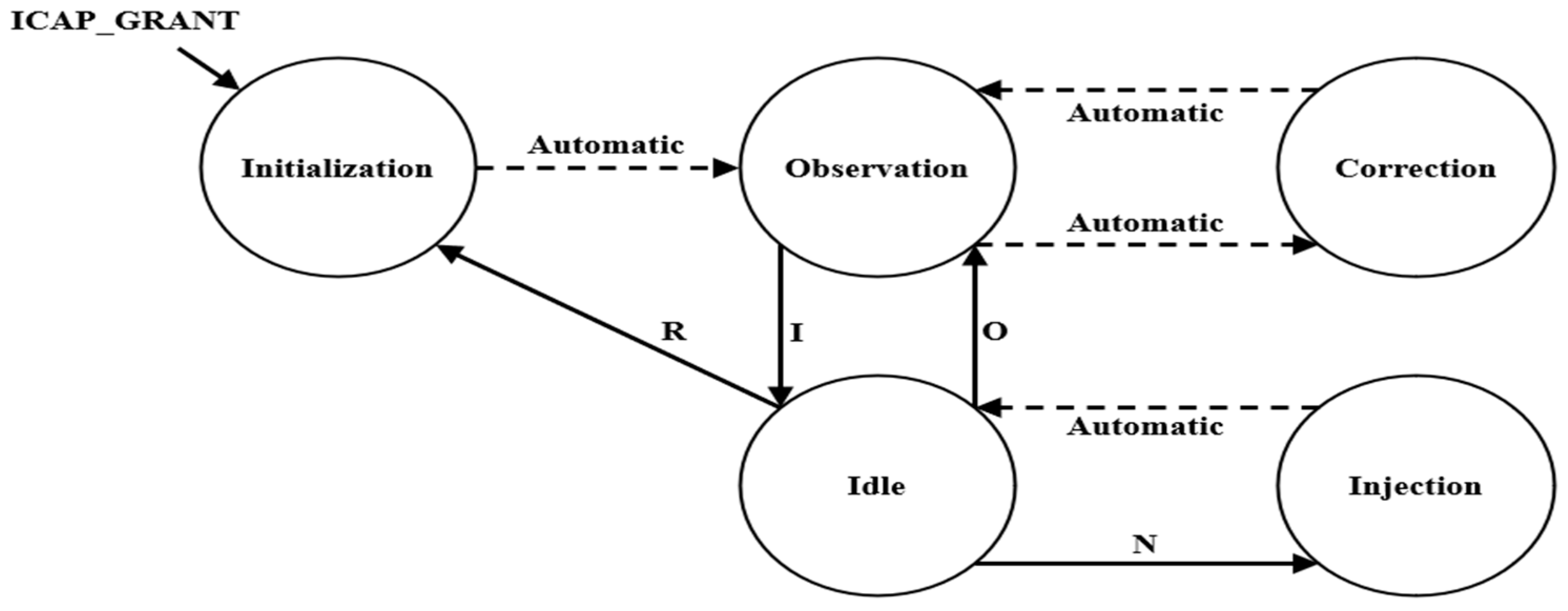
As shown in Figure 3, SEM IP operates in five states (initialization, observation, IDLE, injection, and correction) according to external commands. This action can be observed in the waveform using the Integrated Logic Analyzer (ILA) tool, as shown in Figure 4. SEM IP consists of several states, and the description of each state is as follows:

Figure 3.
Soft error mitigation IP state diagram.

Figure 4.
Soft error mitigation IP waveform.
Step 1: Initialization State
- This is the initial state for activating SEM IP. This step checks whether the configuration memory is accessible and whether SEM IP is operating normally.
- If it can operate normally, it automatically enters the observation state.
- When the ICAP_GRANT signal is applied, it enters the initialization state.
- Upon entering the relevant state, the “status_initialization” signal among the output signals of SEM IP is set to high (the remaining signals are low) to indicate the current state.
Step 2: Observation State
- This state monitors the configuration memory for faults.
- It automatically enters the initialization state and can transition to the IDLE state using a specific command (the “I” command).
- Upon entering the relevant state, the “status_observation” signal among the output signals of SEM IP is set to high (the remaining signals are low) to indicate the current state.
Step 3: IDLE State
- The user waits for a command to be input to request a specific task from SEM IP.
- The users can perform the following tasks using specific external commands (R, N, O, etc.):
- (1)
- R command: Switch to SEM IP initialization state.
- (2)
- N command: Access the desired configuration memory bit with a combination of ‘N’ and 10 hexadecimal numbers and inject a bit flip-flop fault (refer to Section 3.1.2).
- (3)
- O command: Switch to SEM IP observation state.
- Upon entering the corresponding state, all output signals of SEM IP go to low to indicate the current state.
Step 4: Injection State
- This is a state in which the fault injection location (configuration memory address) commanded by the user is identified, and a flip-flop is triggered for the bit at the identified location.
- Once the fault injection is completed, it automatically transitions to the IDLE state and waits to receive the next command.
- Upon entering the relevant state, the “status_injection” signal among the output signals of SEM IP goes high (the remaining signals are low) to indicate the current state.
Step 5: Correction State
- This is a state in which the bit errors in the configuration memory are periodically monitored, and when a single bit error occurs, error correction and error classification are performed for the error.
- It automatically transitions to the correction state from the observation state.
- Upon entering the relevant state, the output signal of SEM IP is set according to fault identification and classification, as follows:
- (1)
- Fault observation: The “status_observation” signal is set to high (the remaining signals are low).
- (2)
- Fault detection: The “status_correction” signal is set to high (the remaining signals are low).
- (3)
- Fault classification: The “status_classification” signal is set to high (the remaining signals are low).
3.1.2. Fault Injection Control
Accessing the configuration memory using SEM IP is possible by sending the corresponding command through serial communication. To apply a fault to a desired memory address, a comprehension of linear frame addresses is necessary. This is explained in detail in Reference [13]. In this paper, to inject faults into the Zynq-7000 series board (Digilent Inc., Pullman, WA, USA), the linear frame address for the board was analyzed, and a fault injection engine based on this analysis was integrated into the ACMFI tool.
To execute the desired fault command, the SLICE location information of the CLB where the DUT is synthesized is required. The logic location file (.ll) provides the CLB location of the synthesized logic. However, because logic location is sensitive information that can potentially lead to bitstream hacking, not all of the information is disclosed. If the information about the circuit to be analyzed is not available in the logic location, users can verify the CLB location through the floor plan created during the implementation stage.
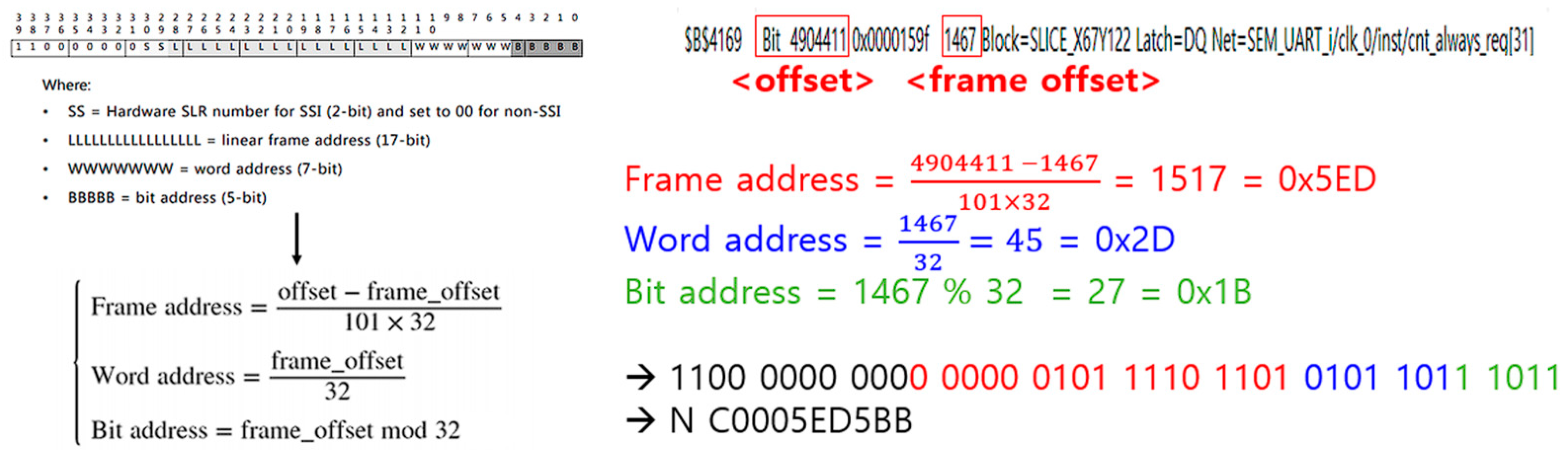
There are two methods (linear frame address and physical frame address) that can be used to apply a fault to a desired address location using SEM IP [30]. In this paper, we only discuss how to generate fault injection commands using linear frame addresses (hereinafter referred to as LFA). The fault injection command using LFA requires 10 words of information along with “N”. Each word is expressed as a hexadecimal ASCII word, and, as a result, 40 bits of information are required. These 40 bits of information consist of a fixed ‘11000000’, 2 bits of hardware SLR code, 17 bits of linear frame address, 7 bits of word address, and 5 bits of bit address. To obtain this information, the offset information and frame offset information about the fault injection location are necessary, and they can be found in the logic location file.
This explains how to create a fault injection command to inject a fault into the $B$4169 cell using the logic location file. We can verify in the logic location file that the offset of the cell in question is 4904411, and the frame offset is 1467. In this example, because non-SSI is set, the SLR code is ‘00’. Figure 5 illustrates the process of generating a fault injection command using the provided information.
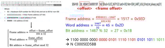
Figure 5.
Generating fault injection commands through Linear Frame Address.
3.1.3. Statistical Fault Injection Test
Injecting faults into all cells can ensure accurate test results but requires a significantly extended time period [31]. Additionally, if a fault is applied to components other than the DUT (e.g., an external module introduced to inject faults, etc.), it may lead to inaccurate failure results (injection side effects). To address this issue, this study restricts fault injection to the DUT and presents a framework for statistical fault injection.
First, SLICE information is essential to limit fault injection to the DUT. However, when implementation is conducted after general synthesis, the module (test module) for fault injection by the user is distributed across various slices and undergoes synthesis. This presents the challenge of having to run the FPGA Fault Injection Tool using SLICE multiple times, which can be a cumbersome and time-consuming process.
To overcome this, after synthesis, the p-block function must be employed to specify a particular SLICE range for synthesis enablement. P-block is a function provided by Xilinx, allowing the netlist for a specific sub-block to be placed at a designated location during the floor planning stage. Figure 6 depicts the floor planning results after configuring the p-block for the PRINCE circuit and performing the implementation. We can observe that the blue color was properly synthesized in the area where the p-block was placed as the test module.
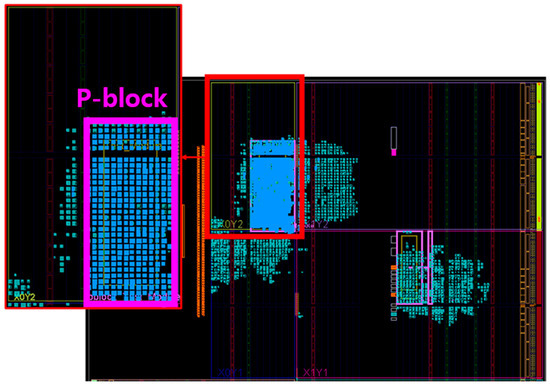
Figure 6.
P-block Floor Planning.
To determine the number of statistical fault injection tests for a limited fault injection location, we can use the following formula to select the number of tests based on the confidence interval and error margin. In the equation below, n represents the total number of tests, and e denotes the error margin value, typically set at 1%. N represents the fault injection space (memory coverage), which can be obtained in the previous step. The t is a confidence level factor, and its value varies depending on the desired confidence interval. For a 90% confidence interval, The t is 1.645; for a 95% confidence interval, t is 1.96; and for a 99% confidence interval, The t is 2.58. Lastly, p is a statistical parameter, assumed to be the worst-case value, and is typically set to 0.5.
- n = total number of tests, N = Fault Injection Space,
- e = error margin (1%), t = confidence level factor (CI 95% = 1.96),
- p = statistical parameter (worst − case value = 0.5).
3.2. Automatic Configuration Memory Fault Injection Tool
3.2.1. Architecture
The Automatic Configuration Memory Fault Injection Tool (ACMFI) is a tool that automates statistical fault injection tests for FPGA configuration memory using SEM IP. The FPGA Fault Injection Tool determines the location of the CLB (configuration logic block) where the designed circuit is synthesized and generates a list of statistical fault injection test scenarios that can randomly inject faults (single-bit flips) within the specified memory range. This list is subsequently applied sequentially to the target board, and the results of each test scenario are recorded. Finally, the results of the statistical fault injection scenario list are compiled, and the overall failure rate is provided.
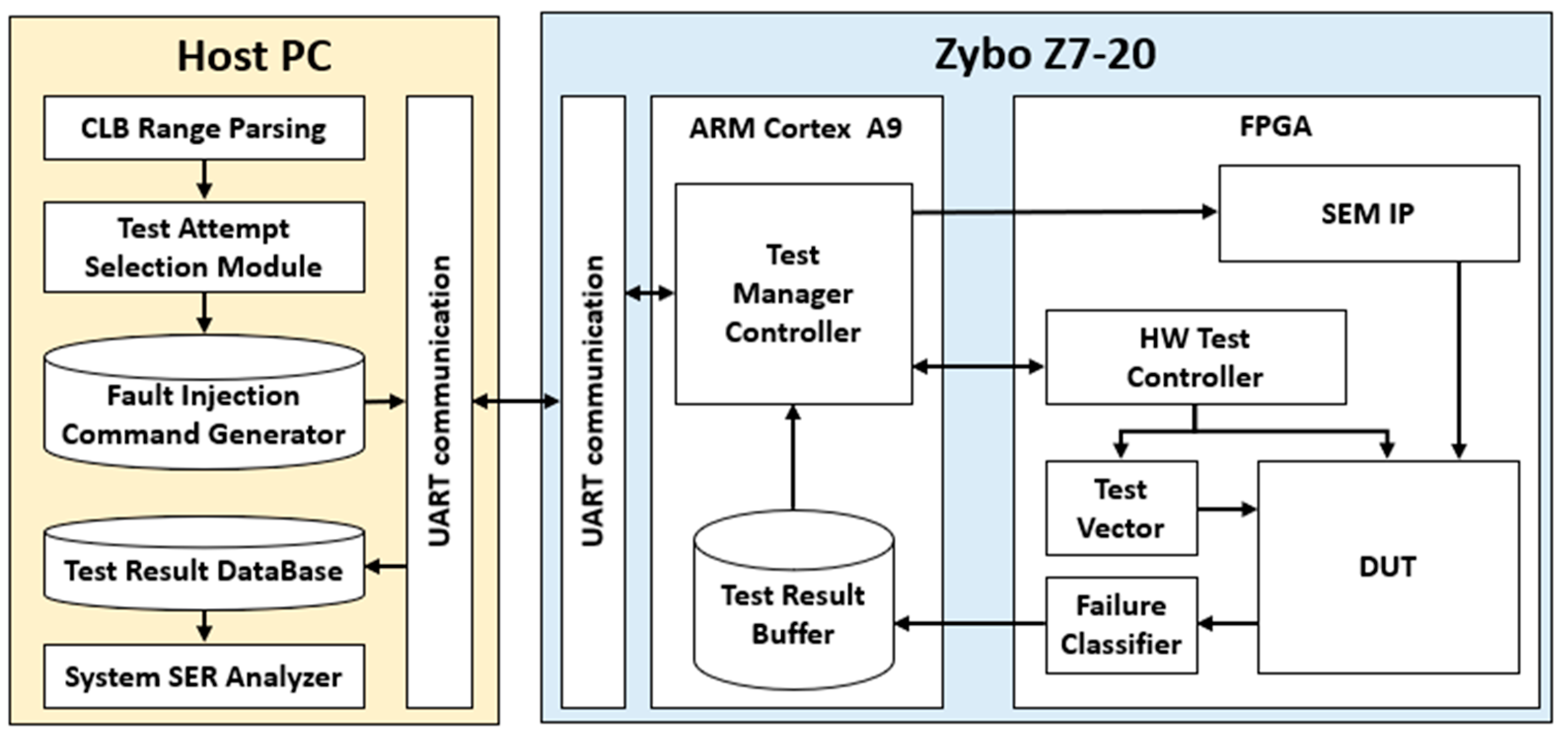
The ACMFI architecture comprises a host PC and a target board (Zybo Z7-20 Board (Xilinx, Taiwan)), as illustrated in the Figure 7. The host PC receives statistical fault injection test information from the target board (including the test scope and scenarios), conducts the tests automatically, and presents the performance results to the user in a list format. The target board executes the fault injection test scenarios configured on the host PC for the implemented circuit and communicates the output results (normal or failed) back to the host PC. The final system SER is computed based on the received test results.
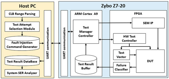
Figure 7.
Automatic Configuration Memory Fault Injection architecture.
3.2.2. Function
The ACMFI tool provides the capability to automatically conduct statistics-based fault injection testing and can analyze the results through three tabs.
- (1)
- Test Scenario Setting
- SLICE Region: Allows the user to define the area for fault injection (based on the SLICE region of the configuration memory). It calculates the total number of bits within the specified fault injection range and presents the result to the user.
- Confidence Interval: Enables the selection of the number of test repetitions for statistical fault injection testing.
- Number of Tests: Displays the final number of tests based on the fault injection range and chosen confidence interval.
- Test Scenario: Automatically generates fault injection commands in accordance with the number of tests.
- (2)
- Automatic Testing
- Target Board Communication Connection: Offers a COM port connection feature for connecting to the target board.
- Message: A window to verify the status of the target board and whether reception was successful.
- Send Message: Provides a function for inputting single fault injection commands.
- Test Start/Finish Time: Indicates the start and end times for the statistical fault injection test.
- Test Start: Conducts the fault injection test and presents the results based on a predefined test scenario.
- (3)
- Test Result Analysis
- SEU Setting: Configuration of single-event upset (SEU) parameters obtained from the literature research.
- AVF Result: Presentation of AVF results based on the automatic fault injection test outcomes.
- CM Size: Display of memory bit size corresponding to the fault injection test range.
- Test Result: Reports the final system SER and provides reliability and failure probability based on .
3.2.3. Statistical Fault Injection Testing Process Using ACMFI
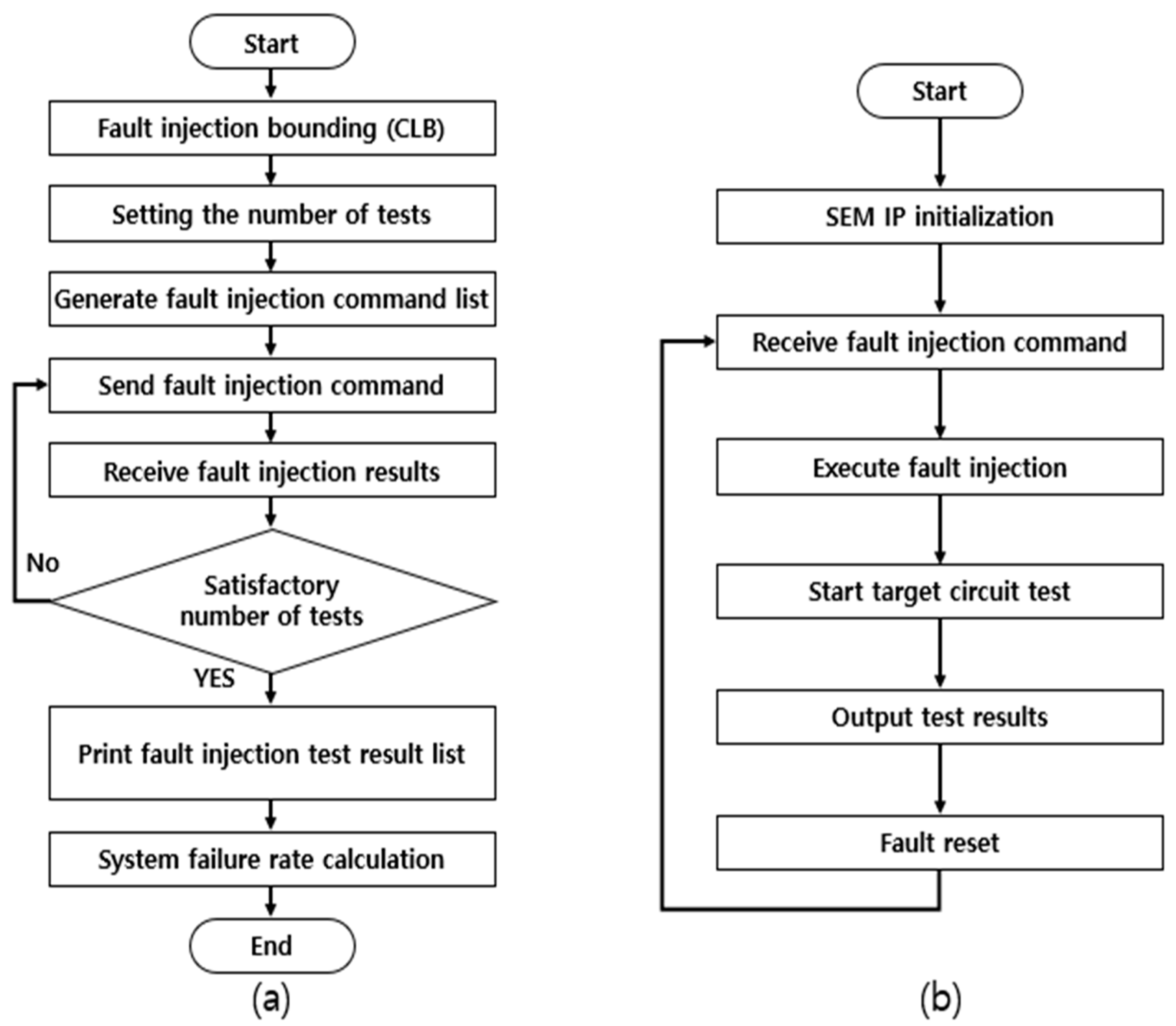
This section explains the process of statistical fault injection testing using ACMFI. Figure 8 illustrates the system flowchart of the host PC and the target board in accordance with the statistical fault injection testing process. The statistical fault injection testing procedure using the ACMFI tool mainly involves three steps, and each sub-process is outlined in Figure 9. In this section, the statistical fault injection testing procedure using the ACMFI tool is explained in detail, based on each sub-process.

Figure 8.
System Flow Chart ((a) Host PC and (b) Zybo Z7-20 Board).
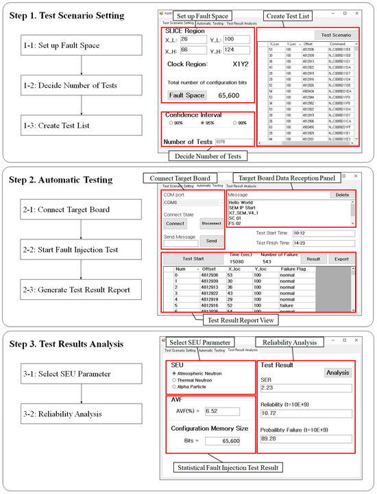
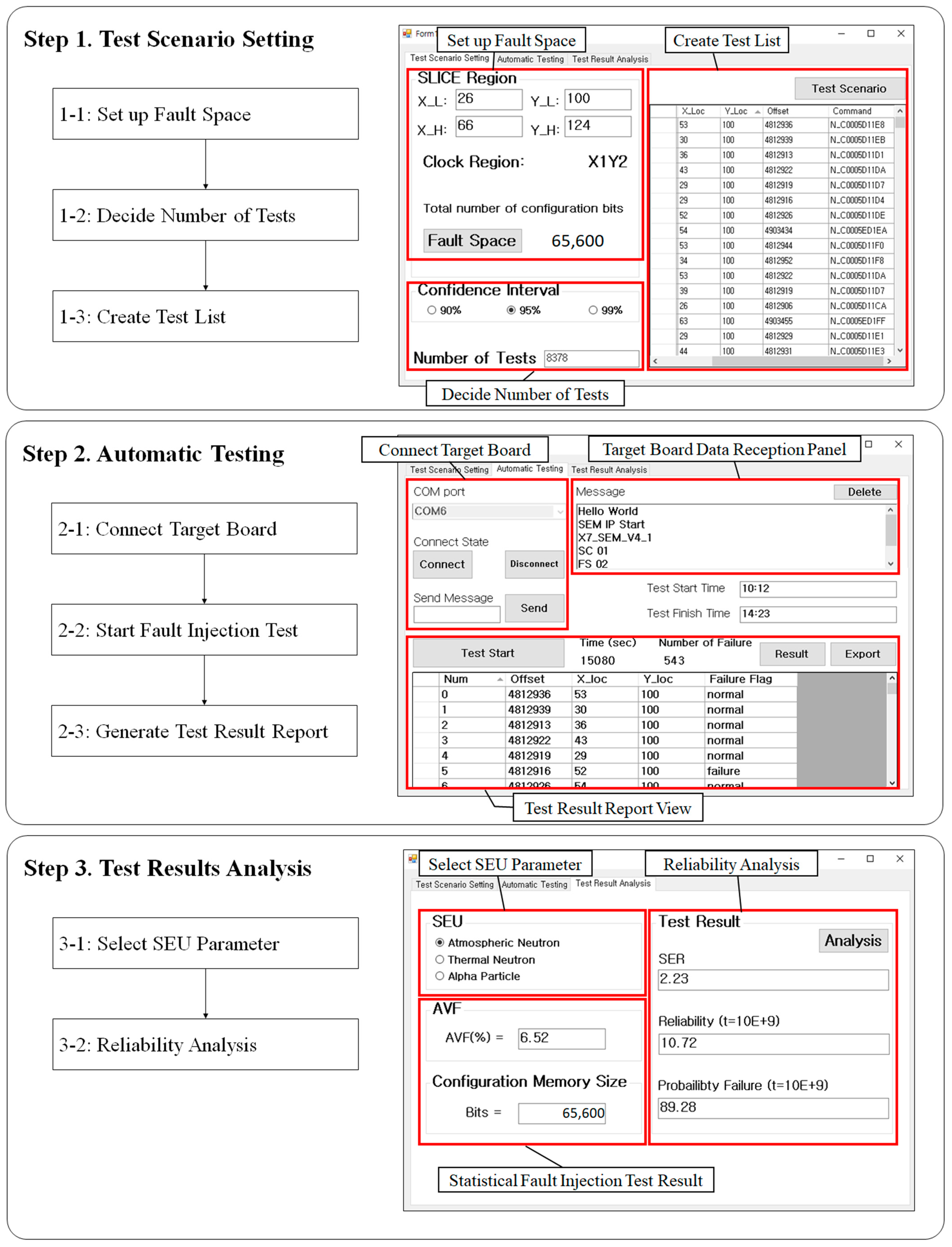
Figure 9.
Automatic Configuration Memory Fault Injection operation flowcharts and captures.
Step 1-1: Set Up Fault Space
This is the stage where the user selects spatial information for fault injection. The user should click on the “Test Scenario Setting” tab, input the X and Y coordinates of the identified CLB accurately, and then click the “Fault Space” button. When this task is completed, the FPGA Fault Injection Tool identifies the clock region from the input information and presents the user with the fault injection range (memory range), as shown Figure 10.
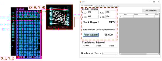
Figure 10.
Set up fault injection space.
Step 1-2: Decide Number of Tests
The step for setting the number of fault injection tests is a procedure for configuring the test quantity in statistical fault injection testing. Once the user specifies the desired confidence interval, the number of tests that fulfill that criterion is computed. When the user clicks the preferred confidence interval button within the “Confidence Interval (CI)” group box, the number of tests at the bottom is generated automatically. For example, we can observe that the number of tests satisfying the 95% confidence interval for one SLICE (X_L: 47 Y_L: 100 / X_H: 66 Y_H: 124) is set to 8378.
Step 1-3: Create Test List
Generating a fault injection command list is a step in which a fault injection location is randomly selected within a specified fault injection range for the chosen number of tests, and a corresponding fault injection command is generated. The fault injection command can be represented as 10 hexadecimal ASCII words combined with the “N” instruction. The structure of the word is illustrated in the diagram below, and the user is responsible for creating a command accordingly and inputting it into the SEM IP. Clicking the “Test Scenario” button in the upper right corner generates SLICE information and fault injection commands for the predetermined number of tests, then displays them to the user.
Step 2-1: Connect Target Board
Connecting the target board is a step used to verify if normal operation has been established after connecting the host PC and the target board (Zybo Z7-20) through micro-USB. They establish a connection via UART serial communication, and the target board sends a SEM IP initialization report to the host PC. The transmitted report information can be viewed in the reception window of the FPGA Fault Injection Tool. The user should go to the “Automatic Testing” tab and configure the port number for the target board then click the “Connect” button. When the port connection is successfully established, the port is opened, and the message changes. Following this, when we initiate the target board, the SEM IP report window appears in the receiving window. The Figure 9 illustrates the result screen for a successful connection to the target board.
Step 2-2: Start Fault Injection Test
The fault injection test is an automated step in which the commands from the fault injection command list created in step three are sequentially transmitted to the SEM IP of the target board, and the test results are received. The test results are categorized as either “normal” or “failure”, and any deviation from the golden module result is considered a “failure”. The test concludes when the selected number of tests is completed or when the target board fails to self-recover. Clicking the “Test Start” button at the bottom initiates the process.
Step 2-3: Generate Test Result Report
Upon the completion of the statistical fault injection test, the test concludes with a test completion message. After the test is finished, we can review the test results by clicking the “Results” button located in the center-right. Additionally, we can click the “Export” button to generate an output in Notepad format.
Step 3: Test Results Analysis (Select SEU Parameter and Reliability Analysis)
After completing the test results, the user should click on the “Test Results Analysis” table. Then, to automatically calculate the system SER, the user should choose the SEU value for the desired particle in the SEU selection window. SEU stands for , and is a value that refers to data from previous experiments or reports [32,33].
3.3. Soft Error Rate Estimation
To assess the reliability of the target board circuit, which is one of the primary objectives of this study, we obtain the soft error rate (SER). The SER represents the rate at which a system fails due to soft errors and is typically expressed as FIT [34,35,36,37,38,39]. The commonly used value can be defined by the following equation. In this equation, is a key indicator that assesses the sensitivity of the designed circuit to radiation. It is defined as the ratio of the number of errors observed in the system’s output to the particle collision influence. represents the number of particles passing through per unit time and unit area.
However, since is a result obtained by synthesizing an actual target circuit, it is typically necessary to reference previously researched results or to conduct a direct radiation test. Nevertheless, obtaining research results using the same circuit on the same board can be realistically challenging. To address this, we utilize , as presented in [38,39].
is an intrinsic device parameter, typically expressed in surface area (cm²/bit), representing the minimum sensitive surface area of the device to particle types (e.g., neutron, proton, neutral ion, etc.) and particle energy (LET), as indicated by Ref. [4]. This parameter exclusively denotes the radiation sensitivity concerning memory and is relatively more straightforward to utilize than . AVF, on the other hand, signifies the probability of system failure when a soft error occurs. Ultimately, can be summarized as follows: can be obtained from data such as those from previous experiments or reports [32,33], and AVF can be calculated using statistical fault injection testing conducted with the ACMFI developed in this paper.
4. Test Result
4.1. Test Environment
The FPGA Fault Injection Tool environment consists of a host PC and a target board (Zybo Z7-20). The specifications of the host PC and the Zybo Z7-20 board used in this study are presented in Table 2. The host PC and the Zybo Z7-20 board are connected via micro-USB, and the data are transmitted and received through UART serial communication.
Table 2.
Test environment SPEC.
In this study, four security circuits (DES, AES, RSA, and SHA) were selected as the target circuits for the DUT (device under test), and fault injection tests were conducted. DES and AES are both symmetric key cryptographic algorithms used to protect data confidentiality, while RSA is an asymmetric key algorithm designed to support secure data transmission and digital signatures. SHA plays a crucial role in verifying data integrity. These circuits represent essential cryptographic technologies and are widely used cryptographic modules that establish benchmark standards in real systems. Evaluating the sensitivity of systems equipped with these modules to SER (soft error rate) is a critical task for enhancing overall system security.
4.2. Test Vector: Open-Source-Based ATPG System
A single test vector is required for repetitive FPGA fault injection testing. If a single test vector is insufficient, potential faults may go unnoticed, which can result in an inappropriate performance evaluation. To mitigate this issue, we have established an open-source Automatic Test Pattern Generator (ATPG) environment using ATALANTA, an ATPG tool.
The open-source ATPG environment comprises two programs, YOSYS and ATALANTA, running on a host PC (Ubuntu environment). YOSYS is open-source software for Verilog HDL synthesis, allowing for file format conversion by synthesizing multiple Verilog circuits [40,41]. ATALANTA is an open-source ATPG tool developed at the University of Virginia [15]. After converting the Verilog file into a bench file, which serves as ATALANTA’s input data, using YOSYS, ATPG is performed with ATALANTA to generate the testbench list for the target circuit.
The system architecture of the open-source ATPG consists of YOSYS and ATALANTA in Figure 11. YOSYS takes the Verilog file (*.v) of the fault injection target circuit for each module, synthesizes them into a single file, and converts the file format to a blif file. This file format is then transformed into a bench file using YOSYS-ABC. Running the ATALANTA program with the bench file created in this manner generates a testbench file for the circuit. For the four types of security circuits, each fault coverage was selected to achieve a minimum of 90%, and the test vectors for input to each security circuit were secured.
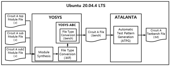
Figure 11.
Open-source-based ATPG system architecture.
4.3. Results and Discussion
The results of the statistical fault injection testing using the ACMFI tool are summarized in Table 3. The table includes resource information, the fault injection range, the test results, and the final SER estimation results for the four target security circuits (AES, SHA, RSA, and DES). To calculate the , as determined in this study, we utilized the values from reports and papers conducted on the same 28-nm Zynq-7000 series board.
Table 3.
Soft error rate estimation.
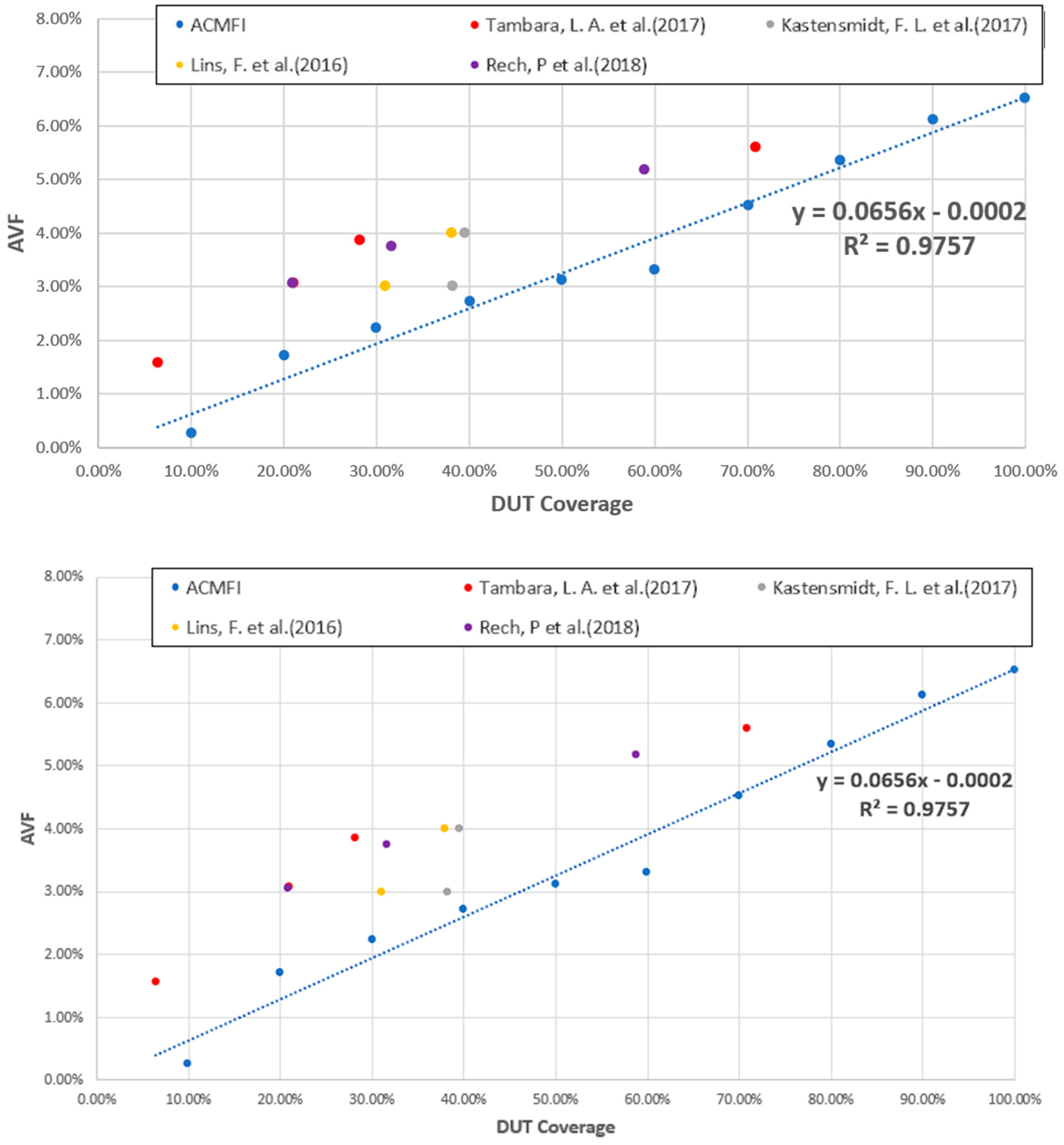
Using linear regression analysis of AVF, according to DUT coverage, we have confirmed that the ACMFI tool developed in this study can mitigate the side effect problem. The side effect problem occurs when the AVF falls below the ideal result due to defect injection into an area other than the specific target intended for analysis. With the ACMFI tool developed in this study, we were able to address this issue by intentionally injecting defects into specific target locations within the device under test (DUT).
Figure 12 displays AVF values according to DUT coverage for the AES circuit. DUT coverage refers to the range of the target DUT versus the range of the defect injection. The higher the DUT coverage, the smaller the side effect. The graph reveals two key findings. Through the linear regression of the AVF values, with respect to DUT coverage, the equation was derived, and the coefficient of determination () was found to be 0.9757. This high value signifies a strong linear relationship between DUT coverage and AVF values, indicating that higher DUT coverage leads to more accurate AVF estimations.
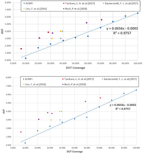
Figure 12.
DUT coverage and AVF comparison graph [36,42,43,44].
This observed trend is also consistent with the results of other studies conducted under similar experimental conditions. This is a study that performed a neutron beam test by synthesizing a AES circuit [36,42,43,44]. Beam testing was performed on the entire memory, but the bitstreams synthesized in the memory were different depending on the option. Using this, the DUT coverage was obtained, and the corresponding AVF results are summarized in Figure 12. Looking at the graph in Figure 12, we can see that the AVF increases according to DUT coverage.
In this study, to perform reliability analysis on the target board, we applied reliability modeling following an exponential distribution using the obtained [31]. Since the target board was a single board without redundancy, we used exponential distribution reliability modeling with a constant failure rate (). The failure rate was directly derived from the formula , where stands for mean time to failure, and this could be replaced by SER (). The reliability function R(t) was the complement of the cumulative failure function , therefore, .
This reliability model clearly shows the side effect problem. Figure 13 is a result of applying the SER values obtained from the emulation tests and beam tests of boards similar to the Zynq-7000 series to the reliability model [34,36,45,46]. Other emulation studies have shown that the AVF is underestimated due to the existing side effect problem, resulting in higher reliability compared to the actual beam test results. On the other hand, using the ACMFI tool developed in this study, it was possible to obtain similar beam test results by mitigating the side effect problem.

Figure 13.
Reliability of the Zynq-7000 SER.
5. Conclusions
This paper presents a comprehensive analysis of the system error rate of the configuration memory in the SRAM-based FPGA, with a focus on soft errors. To achieve this goal, we created test vectors with more than 90% fault coverage using ATALANTA, an open-source ATPG tool. Based on the generated test vectors, we conducted a statistical fault injection test with a confidence interval of 95% (error 1%) using the developed ACMFI tool for four types of target security circuits. The AVF was calculated based on the results, and the for each security circuit was determined using data obtained from the literature.
Utilizing the ACMFI tool, we accurately identified and assessed soft errors in the programmable logic of the AES circuit. This tool enabled us to pinpoint and analyze soft errors at specific target locations within the device under test (DUT), specifically within the configuration memory synthesizing the security circuit. Our approach effectively eliminates the problem of underestimating the architectural vulnerability factor (AVF) values due to side effects, as demonstrated by the strong linear correlation between the DUT coverage and the AVF values, accompanied by a high coefficient of determination ().
In this study, we conducted a reliability analysis on a target board using exponential distribution reliability modeling based on the estimated soft error rate. Previous studies have suggested that the architectural vulnerability factor (AVF) may be underestimated due to side effect problems, which can lead to overestimated reliability compared to actual beam test results. However, while the ACMFI tool excels at identifying and analyzing soft errors within an SRAM configuration memory, it is limited in its ability to cover the remaining components of the FPGA, such as the processor core, Block RAM, DSP blocks, and IO blocks. For future research, it is necessary to enhance the functionality of SEM IP and to inject faults into the processor core or BRAM in order to estimate AVF and SER in a manner that is more aligned with actual testing conditions than those that are currently available.
Author Contributions
The experiment, data analysis, and writing of the paper were conducted by D.L.; the experimental methodology and data review were completed by T.N., D.P. and Y.K.; and the validation, methodology, and paper editing were handled by J.N. All authors have read and agreed to the published version of the manuscript.
Funding
This work was partly supported by the GRRC program of Gyeonggi province (GRRC Korea Aerospace University 2023-B02) and the National Research Foundation of Korea (NRF), grant funded by the Korean government (MSIT) (No. 2022K1A3A1A2001493).
Institutional Review Board Statement
Not applicable.
Informed Consent Statement
Not applicable.
Data Availability Statement
The raw data supporting the conclusions of this article will be made available by the authors on request.
Conflicts of Interest
The authors declare no conflicts of interest.
References
- Chatterjee, I.; Narasimham, B.; Mahatme, N.N.; Bhuva, B.L.; Reed, R.A.; Schrimpf, R.D.; Wang, J.K.; Vedula, N.; Bartz, B.; Monzel, C. Impact of Technology Scaling on SRAM Soft Error Rates. IEEE Trans. Nucl. Sci. 2014, 61, 3512–3518. [Google Scholar] [CrossRef]
- Dodd, P.; Shaneyfelt, M.; Felix, J.; Schwank, J. Production and Propagation of Single-Event Transients in High-Speed Digital Logic ICs. IEEE Trans. Nucl. Sci. 2004, 51, 3278–3284. [Google Scholar] [CrossRef]
- Kastensmidt, F.; Rech, P. Radiation Effects and Fault Tolerance Techniques for FPGAs and GPUs. In FPGAs and Parallel Architectures for Aerospace Applications: Soft Errors and Fault-Tolerant Design; Springer: Cham, Switzerland, 2016; pp. 3–17. [Google Scholar]
- JESD89A; Measurement and Reporting of Alpha Particle and Terrestrial Cosmic Ray-Induced Soft Errors in Semiconductor Devices. JEDEC: Arlington County, VA, USA, 2006.
- Rodriguez, J.; Baldomero, A.; Montilla, V.; Mujal, J. LLFI: Lateral Laser Fault Injection Attack. In Proceedings of the 2019 Workshop on Fault Diagnosis and Tolerance in Cryptography (FDTC), Atlanta, GA, USA, 25 August 2019; IEEE: Piscataway, NJ, USA, 2019; pp. 41–47. [Google Scholar]
- Damkjar, S.E.; Mann, I.R.; Elliott, D.G. Proton Beam Testing of SEU Sensitivity of M430FR5989SRGCREP, EFM32GG11B820F2048, AT32UC3C0512C, and m2s010 Microcontrollers in Low-Earth Orbit. In Proceedings of the 2020 IEEE Radiation Effects Workshop (in Conjunction with 2020 NSREC), Santa Fe, NM, USA, 20–24 July 2020; IEEE: Piscataway, NJ, USA, 2020; pp. 1–5. [Google Scholar]
- Vanat, T.; Pospiil, J.; Kriek, F.; Ferencei, J.; Kubatova, H. A System for Radiation Testing and Physical Fault Injection into the FPGAs and Other Electronics. In Proceedings of the 2015 Euromicro Conference on Digital System Design, Funchal, Portugal, 26–28 August 2015; IEEE: Piscataway, NJ, USA, 2015; pp. 205–210. [Google Scholar]
- Hoflinger, K.; Muller, S.; Peng, T.; Ulmer, M.; Ludtke, D.; Gerndt, A. Dynamic Fault Tree Analysis for a Distributed Onboard Computer. In Proceedings of the 2019 IEEE Aerospace Conference, Big Sky, MT, USA, 2–9 March 2019; IEEE: Piscataway, NJ, USA, 2019; pp. 1–13. [Google Scholar]
- Bodmann, P.R.; Papadimitriou, G.; Junior, R.L.R.; Gizopoulos, D.; Rech, P. Soft Error Effects on ARM Microprocessors: Early Estimations Versus Chip Measurements. IEEE Trans. Comput. 2021, 71, 2358–2369. [Google Scholar] [CrossRef]
- Keshk, M.E.; Asami, K. Fault Injection in Dynamic Partial Reconfiguration Design Based on Essential Bits. J. Aeronaut. Space Technol. 2018, 11, 25–34. [Google Scholar]
- Abad Garcia, C. Error Injection Study for a SpaceFibre In-Orbit Demonstrator. Master’s Thesis, KTH Royal Institute of Technology, School of Electrical Engineering and Computer Science, Stockholm, Sweden, 2020. [Google Scholar]
- Harward, N.A.; Gardiner, M.R.; Hsiao, L.W.; Wirthlin, M.J. Estimating Soft Processor Soft Error Sensitivity Through Fault Injection. In Proceedings of the IEEE 23rd Annual International Symposium on Field-Programmable Custom Computing Machines (FCCM), Vancouver, BC, Canada, 2–6 May 2015; IEEE: Piscataway, NJ, USA, 2015; pp. 143–150. [Google Scholar]
- Aranda, L.A.; Sánchez-Macián, A.; Maestro, J.A. ACME: A Tool to Improve Configuration Memory Fault Injection in SRAM-Based FPGAs. IEEE Access 2019, 7, 128153–128161. [Google Scholar] [CrossRef]
- Mao, C.A.; Xie, Y.; Wei, X.; Xie, Y.Z.; Chen, H. FPGA-Based Fault Injection Design for 16K-Point FFT Processor. J. Eng. 2019, 2019, 7994–7997. [Google Scholar] [CrossRef]
- Lee, H.K.; Ha, D.S. On the Generation of Test Patterns for Combinational Circuits; Technical Report; Virginia Polytechnic Institute and State University, Department of Electrical Engineering: Blacksburg, VA, USA, 1993. [Google Scholar]
- Madeira, H.; Rela, M.; Moreira, F.; Silva, J.G. RIFLE: A General Purpose Pin-Level Fault Injector. In Proceedings of the 1st European Dependable Computing Conference (EDCC-1), Berlin, Germany, 4–6 October 1994; Springer: Berlin/Heidelberg, Germany, 1994; pp. 199–216. [Google Scholar]
- Choi, G.S.; Iyer, R.K. FOCUS: An Experimental Environment for Fault Sensitivity Analysis. IEEE Trans. Comput. 1992, 41, 1515–1526. [Google Scholar] [CrossRef]
- Martínez, R.J.; Gil, P.J.; Martín, G.; Pérez, C.; Serrano, J.J. Experimental Validation of High-Speed Fault-Tolerant Systems Using Physical Fault Injection. In Proceedings of the Dependable Computing for Critical Applications 7 (DCCA-7), San Jose, CA, USA, 6–8 January 1999; Volume 12, pp. 249–265. [Google Scholar]
- Dawson, S.; Jahanian, F.; Mitton, T. ORCHESTRA: A Probing and Fault Injection Environment for Testing Protocol Imple-mentations. In Proceedings of the IEEE International Computer Performance and Dependability Symposium, Urba-na-Champaign, IL, USA, 4–6 September 1996; p. 56. [Google Scholar]
- Stott, D.T.; Kalbarczyk, Z.; Iyer, R.K. Using NFTAPE for Rapid Development of Automated Fault Injection Experiments; Research Report; Center for Reliable and High-Performance Computing, University of Illinois at Urbana-Champaign: Champaign, IL, USA, 1999. [Google Scholar]
- Carreira, J.; Madeira, H.; Silva, J. Xception: A Technique for the Experimental Evaluation of Dependability in Modern Computers. IEEE Trans. Softw. Eng. 1998, 24, 125–136. [Google Scholar] [CrossRef]
- Ruano, O.; Maestro, J.A.; Reyes, P.; Reviriego, P. A Simulation Platform for the Study of Soft Errors on Signal Processing Circuits through Software Fault Injection. In Proceedings of the 2007 IEEE International Symposium on Industrial Electronics, Vigo, Spain, 4–7 June 2007; pp. 3316–3321. [Google Scholar]
- Sieh, V.; Tschache, O.; Balbach, F. VERIFY: Evaluation of Reliability Using VHDL-Models with Embedded Fault Descriptions. In Proceedings of the IEEE 27th International Symposium on Fault-Tolerant Computing, Seattle, WA, USA, 24–27 June 1997; pp. 32–36. [Google Scholar]
- Na, J.; Lee, D. Simulated Fault Injection Using Simulator Modification Technique. ETRI J. 2011, 33, 50–59. [Google Scholar] [CrossRef]
- Na, J.; Lee, D. Acceleration of Simulated Fault Injection Using a Checkpoint Forwarding Technique. ETRI J. 2017, 39, 605–613. [Google Scholar] [CrossRef]
- Warren, K.M.; Sternberg, A.L.; Weller, R.A.; Baze, M.P.; Massengill, L.W.; Reed, R.A.; Mendenhall, M.H.; Schrimpf, R.D. Integrating Circuit Level Simulation and Monte-Carlo Radiation Transport Code for Single Event Upset Analysis in SEU Hardened Circuitry. IEEE Trans. Nucl. Sci. 2008, 55, 2886–2894. [Google Scholar] [CrossRef]
- Ibe, E.; Yahagi, Y.; Yamaguchi, H. Monte-Carlo Simulation for the Effects of Composite Materials on Single Event Effects of Sub-100 nm Semiconductor Devices. In Proceedings of the 2004 Symposium on Nuclear Data, Ibaraki, Japan, 11–12 November 2005; pp. 100–105. [Google Scholar]
- Murley, P.C.; Srinivasan, G.R. Soft-error Monte Carlo Modeling Program, SEMM. IBM J. Res. Dev. 1996, 40, 109–118. [Google Scholar] [CrossRef]
- Tosaka, Y.; Satoh, S.; Oka, H. An Accurate and Comprehensive Soft Error Simulator NISES II. In Simulation of Semiconductor Processes and Devices 2004; Springer: Vienna, Austria, 2004; pp. 219–222. [Google Scholar]
- Xilinx. SEM IP Core. Available online: https://docs.xilinx.com/r/en-US/pg036_sem (accessed on 27 December 2023).
- Benevenuti, F.; Kastensmidt, F.L. Comparing Exhaustive and Random Fault Injection Methods for Configuration Memory on SRAM-Based FPGAs. In Proceedings of the 2019 IEEE Latin American Test Symposium (LATS), Santiago, Chile, 24–27 March 2019; IEEE: Piscataway, NJ, USA, 2019; pp. 1–6. [Google Scholar]
- Xilinx UG116. Device Reliability Report. 2018. Available online: https://docs.xilinx.com/r/en-US/ug116 (accessed on 12 December 2023).
- Fabero, J.C.; Korkian, G.; Franco, F.J.; Mecha, H.; Letiche, M.; Clemente, J.A. Thermal Neutron-Induced SEUs on a COTS 28-nm SRAM-Based FPGA under Different Incident Angles. In Proceedings of the 2021 IEEE 22nd Latin American Test Symposium (LATS), Quito, Ecuador, 12–15 April 2021; IEEE: Piscataway, NJ, USA, 2021; pp. 1–6. [Google Scholar]
- Tambara, L.A.; Rech, P.; Chielle, E.; Tonfat, J.; Kastensmidt, F.L. Analyzing the Impact of Radiation-Induced Failures in Programmable SoCs. IEEE Trans. Nucl. Sci. 2016, 63, 2217–2224. [Google Scholar] [CrossRef]
- Agiakatsikas, D.; Foutris, N.; Sari, A.; Vlagkoulis, V.; Souvatzoglou, I.; Psarakis, M.; Ye, R.; Goodacre, J.; Luján, M.; Kastriotou, M.; et al. Single Event Effects Assessment of UltraScale+ MPSoC Systems Under Atmospheric Radiation. IEEE Trans. Reliab. 2023, 1–13. [Google Scholar] [CrossRef]
- Tambara, L.A. Analyzing the Impact of Radiation-Induced Failures in All Programmable System-on-Chip Devices. Ph.D. Thesis, Universidade Federal do Rio Grande do Sul, Porto Alegre, Brazil, 2017. [Google Scholar]
- Pérez-Celis, A.; Wirthlin, M.J. Statistical Method to Extract Radiation-Induced Multiple-Cell Upsets in SRAM-Based FPGAs. IEEE Trans. Nucl. Sci. 2019, 67, 50–56. [Google Scholar] [CrossRef]
- Tambara, L.A.; Tonfat, J.; Santos, A.; Kastensmidt, F.L.; Medina, N.H.; Added, N.; Aguiar, V.A.P.; Aguirre, F.; Silveira, M.A.G. Analyzing Reliability and Performance Trade-Offs of HLS-Based Designs in SRAM-Based FPGAs under Soft Errors. IEEE Trans. Nucl. Sci. 2017, 64, 874–881. [Google Scholar] [CrossRef]
- Velazco, R.; Foucard, G.; Peronnard, P. Combining Results of Accelerated Radiation Tests and Fault Injections to Predict the Error Rate of an Application Implemented in SRAM-Based FPGAs. IEEE Trans. Nucl. Sci. 2010, 57, 3500–3505. [Google Scholar] [CrossRef]
- Wolf, C.; Glaser, J.; Kepler, J. Yosys-A Free Verilog Synthesis Suite. In Proceedings of the 21st Austrian Workshop on Microelectronics (Austrochip), Linz, Austria, 10 October 2013; p. 97. [Google Scholar]
- YosysHQ. Yosys Open SYnthesis Suite. Available online: https://github.com/YosysHQ/yosys (accessed on 12 December 2023).
- Lins, F.M.; Tambara, L.A.; Kastensmidt, F.L.; Rech, P. Register File Criticality and Compiler Optimization Effects on Embedded Microprocessor Reliability. IEEE Trans. Nucl. Sci. 2017, 64, 2179–2187. [Google Scholar] [CrossRef]
- Lins, F.M.; Tambara, L.; Kastensmidt, F.L.; Rech, P. Register File Criticality on Embedded Microprocessor Reliability. In Proceedings of the 2016 16th European Conference on Radiation and Its Effects on Components and Systems (RADECS), Bremen, Germany, 19–23 September 2016; IEEE: Piscataway, NJ, USA, 2016; pp. 1–5. [Google Scholar]
- Tambara, L.A.; Kastensmidt, F.L.; Rech, P.; Lins, F.; Medina, N.H.; Added, N.; Aguiar, V.A.P.; Silveira, M.A.G. Reliability–Performance Analysis of Hardware and Software Co-Designs in SRAM-Based APSoCs. IEEE Trans. Nucl. Sci. 2018, 65, 1935–1942. [Google Scholar] [CrossRef]
- Lindoso, A.; Entrena, L.; Garcia-Valderas, M.; Parra, L. A Hybrid Fault-Tolerant LEON3 Soft Core Processor Implemented in Low-End SRAM FPGA. IEEE Trans. Nucl. Sci. 2016, 64, 374–381. [Google Scholar] [CrossRef]
- Lopes, I.C.; Benevenuti, F.; Kastensmidt, F.L.; Susin, A.A.; Rech, P. Reliability Analysis on Case-Study Traffic Sign Convolutional Neural Network on APSoC. In Proceedings of the 2018 IEEE 19th Latin-American Test Symposium (LATS), São Paulo, Brazil, 12–15 March 2018; IEEE: Piscataway, NJ, USA, 2018; pp. 1–6. [Google Scholar]


Disclaimer/Publisher’s Note: The statements, opinions and data contained in all publications are solely those of the individual author(s) and contributor(s) and not of MDPI and/or the editor(s). MDPI and/or the editor(s) disclaim responsibility for any injury to people or property resulting from any ideas, methods, instructions or products referred to in the content. |
© 2024 by the authors. Licensee MDPI, Basel, Switzerland. This article is an open access article distributed under the terms and conditions of the Creative Commons Attribution (CC BY) license (https://creativecommons.org/licenses/by/4.0/).