Abstract
The deployable reflector antenna based on the synthetic aperture radar is a satellite component that consists of a unit structure in the form of a folded reflector. During the launch process, this satellite antenna is in the stowed condition to improve storage efficiency. It is then deployed to perform the space mission in the on-orbit condition. Due to these structural characteristics of the deployable reflector antenna, the reflector is possible to be loaded in the limited volume of the launch vehicle with the reduced size. Additionally, because the deployable reflector antenna is made by the lightweight material of the carbon fiber reinforced polymer and honeycomb core, it can reduce the launching cost and improve the revisit interval. In this paper, the conceptual design of the main reflector of the deployable reflector antenna was conducted. The main reflector was designed as the honeycomb sandwich composite structure. To design the main reflector, the stacking sequence of the composite material and honeycomb core was investigated to maximize the structural stiffness and minimize the antenna’s mass. Subsequently, finite element analyses including modal, quasi-static, structural–thermal coupling, and transient response were performed to numerically evaluate the structural performance of the lightweight composite reflector antenna.
1. Introduction
Recently, a next-generation military reconnaissance satellite was developed, built upon three fundamental technologies: high performance, high reliability, and persistence. This type of advanced satellite was designed to execute surveillance and reconnaissance operations with high image resolution across the entire national territory. In this satellite system, the synthetic aperture radar (SAR) antenna is used to facilitate surveillance regardless of observation conditions such as day/night or cloud. Because the SAR antenna has one of the largest payloads in terms of both weight and volume within the satellite system, it should be designed as compact and lightweight as possible. For the compact and lightweight design, a deployable reflector antenna (DR-A) with high storage efficiency was developed by advanced nations like Germany, Israel, Italy, and others [1,2,3,4,5,6,7].
During the process of launching a satellite mounted on a launch vehicle and performing a space mission after reaching mission orbit, the satellite is placed in severe conditions such as quasi-static, vibrational, and acoustic loads or thermal stresses [5,6]. Consequently, the satellite is designed and fabricated to ensure both structural and thermal stability for these extreme loading condition considering the balance between the operational performance and cost. The main reflector has the largest mass ratio except for the electric device among the DR-As. Thus, the design of the main reflector is a key component for improving the performance of the antenna system. Lightweight deployable antenna improves the revisit cycle time for fast satellite operation and facilitates cost reduction for the launch process. The main reflector should be designed to reduce weight while maintaining structural stiffness [8,9,10].
Several works are implemented to design the deployable reflector in the satellite antenna [11]. In order to improve the volume ratio between the deployed and stowed conditions, a mesh-type reflector was developed [12]. Due to the flexibility of the reflecting surface, the satellite equipped with mesh-type antenna is possible to transfer into the on-orbit environment with a limited volume of launch vehicle fairing. But a mesh-type reflecting surface has the bigger shape error than the solid-type antenna. In order to enhance the dynamic stiffness of the solid-type main reflector, the stiffener is applied to thin the CFRP composite reflector. While the CFRP reflective surface to which the stiffener is applied has high dynamic stiffness in the global vibrating mode, the local vibration in the area without the stiffener is large, which reduces the performance of the antenna in terms of attitude control.
In this paper, the main reflector with the honeycomb sandwich composite structure was developed to satisfy the design requirements including size, weight, and structural stiffness. In the design approach, the design variables are the material properties and the laminated stacking sequence of the composite material. Finally, the structural stability of the DR-A developed in this paper is numerically demonstrated using structural analyses of structural mode, quasi-static, thermal gradient, and dynamic behavior. In this paper, the CFRP honeycomb sandwich structure consists of the CFRP material of YSH70A [13] which is space-grade composite material with high strength and the aramid honeycomb core of ECK 4.8 [14]. Also, the shape of the main reflector is axisymmetric Cassegrain type consisting of the main- and sub-reflectors (Table 1).

Table 1.
Design requirements of the deployable reflector [13,14].
In Section 2, the overall design approach is presented. Section 3 shows the sequential design process of the main reflector consisting of the stacking sequence of carbon fiber-reinforced polymer (CFRP) and the spatial distribution of the honeycomb core. Several structural analyses are performed in Section 4. Finally, he structural analyses are implemented for the payload level of satellite antenna in Section 5.
2. Design Approach of Deployable Reflector Antenna
In this study, the design specifications for the deployable antenna are identified based on the performance and functional requirements of representative SAR satellites. Considering the RF (radio frequency) performance of the satellite antenna, the diameter of the main reflector should be over 5000 mm. The total mass of the DR-A in the antenna should be under 110 kg considering the SAR satellite system of a 500 kg weight. Because of the dynamic loads during the launch process, it is important to prevent the interaction of structural resonance between the launch vehicle and the satellite. For this reason, there is a design requirement for the structural mode frequency of the satellite system. In order to design the primary payload such as an SAR antenna, the frequency requirement for primary payload should be satisfied. By these stiffness requirements, the mode frequency of the antenna should be 33 Hz, which is determined by the user manual of overseas launch vehicles [15,16]. In order to evaluate the structural stability of the antenna under the launch environment, it is assumed that this antenna is subjected to the quasi-static load condition of 15 g for the directions of the x, y, and z axes. For the on-orbit condition, the structural–thermal coupled analysis is investigated to calculate the temperature distribution of the main reflector and the transient vibration analysis is examined using the pre-image maneuver of the satellite antenna. As mentioned above, the DR-A has a parabolic-shaped reflecting surface composed of 24 unit structures.
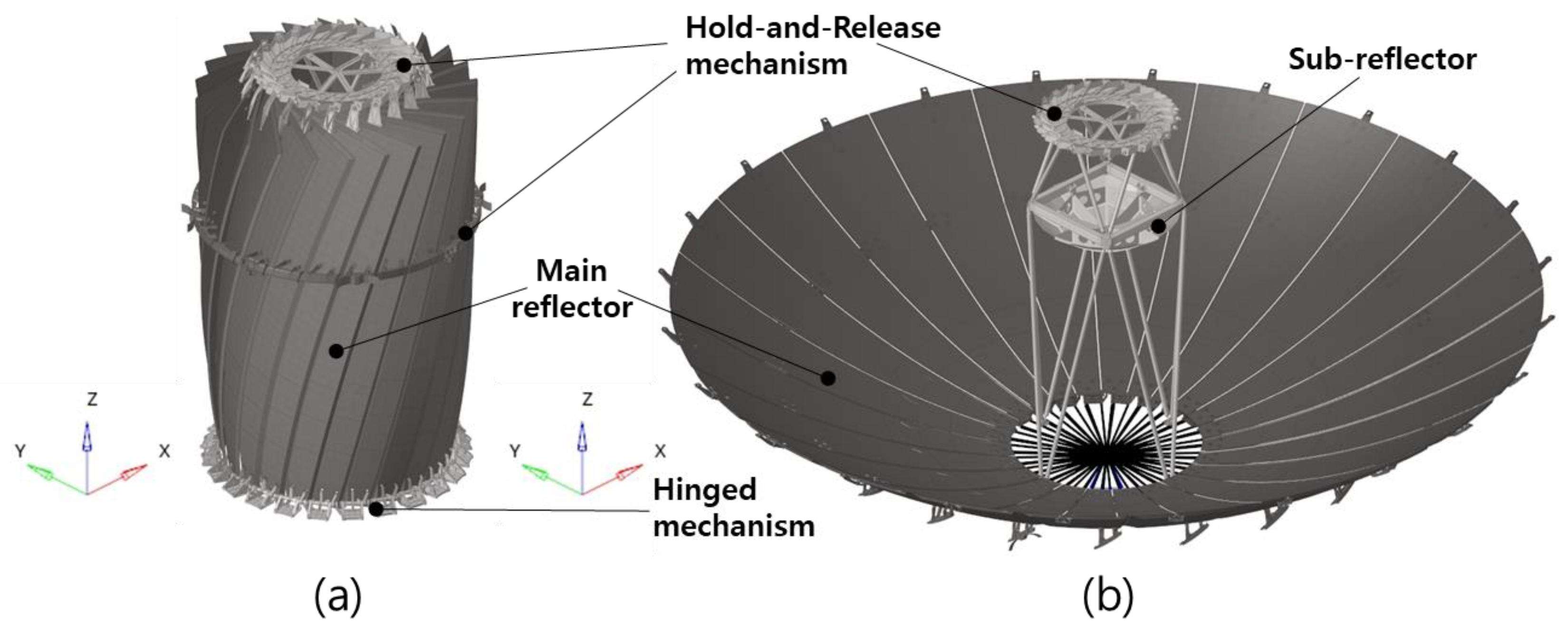
As shown in Figure 1, the deployable antenna is stowed in a launch vehicle. In this regard, the main reflector of the DR-A was designed based on the sandwich composite consisting of the high-stiffness CFRP skin and honeycomb core. In order to achieve the lightweight design with high stiffness, the honeycomb sandwich composite structure in this paper is laminated by the space-grade CFRP facesheet of YSH70A which has a high strength of over 500 GPa, and the honeycomb core of ECK 4.8 with the low-density aramid. First of all, the stacking sequence of the CFRP facesheet and the distribution of ECK 4.8 core are sequentially designed using modal analysis of the unit structure of main reflector. Applying the layout of the unit structure designed in this paper, the finite element analyses of the unit structure and satellite level are implemented to evaluate structural and thermal performance.
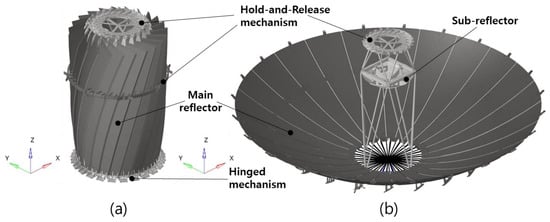
Figure 1.
Deployable reflector antenna under (a) stowed and (b) deployed conditions.
3. Design of the Unit Structure of the Main Reflector in the Deployable Reflector Antenna
3.1. Performance Evaluation According to Stacking Sequence of Facesheet
The composite material is an orthotropic material which has different mechanical properties depending on the stacking angle. In this paper, YSH70A is applied to the main reflector. This material is s space-grade high-strength CFRP structure, and it is manufactured using a plain weaving process. The main reflector is a honeycomb sandwich composite structure, a structure in which the composite material of YSH70A surrounds the upper and lower surfaces of the honeycomb core. To evaluate the influence of the laminated pattern, a parameter study of modal analysis was performed on several types of the unit structure consisting of an Aramid core with the same physical/dimensional properties and YSH70A with different laminated patterns. As shown in Table 2, five cases were selected with the lamination angles of [0, 30, 45, 90]deg. To compare the mechanical performance for each case, the effective properties of the laminated structure are possible to calculate according to Classical Laminate Theory (CLT) [17,18].
Table 2.
Lamination Sequence and Effective Modulus.
In order to numerically evaluate dynamic stiffness, the modal analysis of the unit structure with respect to the laminated pattern of the CFRP facesheet was performed using Optistrut Solver. The finite element model of the unit structure consists of a 2D composite shell element of the YSH70A facesheet and the Aramid core of a 3D anisotropic solid element. To compare the dynamic stiffness values with respect to the laminated pattern, modal analysis was performed under the free–free boundary condition. During the deployment process, the root part of the main reflector is connected to the hinged mechanism adjacent to the center of gravity. The dynamic stiffness of the fully deployed main reflector shown in Figure 1b depends on the root part of the main reflector connected to the hinge. Thus, the dynamic stiffness of the main reflector is evaluated as the first mode frequency.
Table 3 shows the modal analysis results of each main reflector under the free boundary condition with respect to the stacking pattern of the CFRP facesheet. While the first and second mode frequencies for Case 1.2 show a high value, the third mode shows a relatively low value because this laminated pattern has relatively low shear modulus. The laminated pattern of [0/90] has the highest first mode frequency at 30.75 Hz, but the mode frequency for the twisting mode is shown to be significantly low. The second bending mode of Case 1.1 with the laminated pattern of [0/45] is shown the highest at 78.09 Hz, and the torsional mode of Case 1.5 with the laminated pattern of [−30/30] is shown the highest at 116.95 Hz. The laminated pattern with Case 1.1 of [0/45] is reasonable for the main reflector in the DR-A.
Table 3.
Results of Modal Analysis for Laminate Sequence.
3.2. Performance Evaluation According to Honeycomb Core of Reflector Antenna
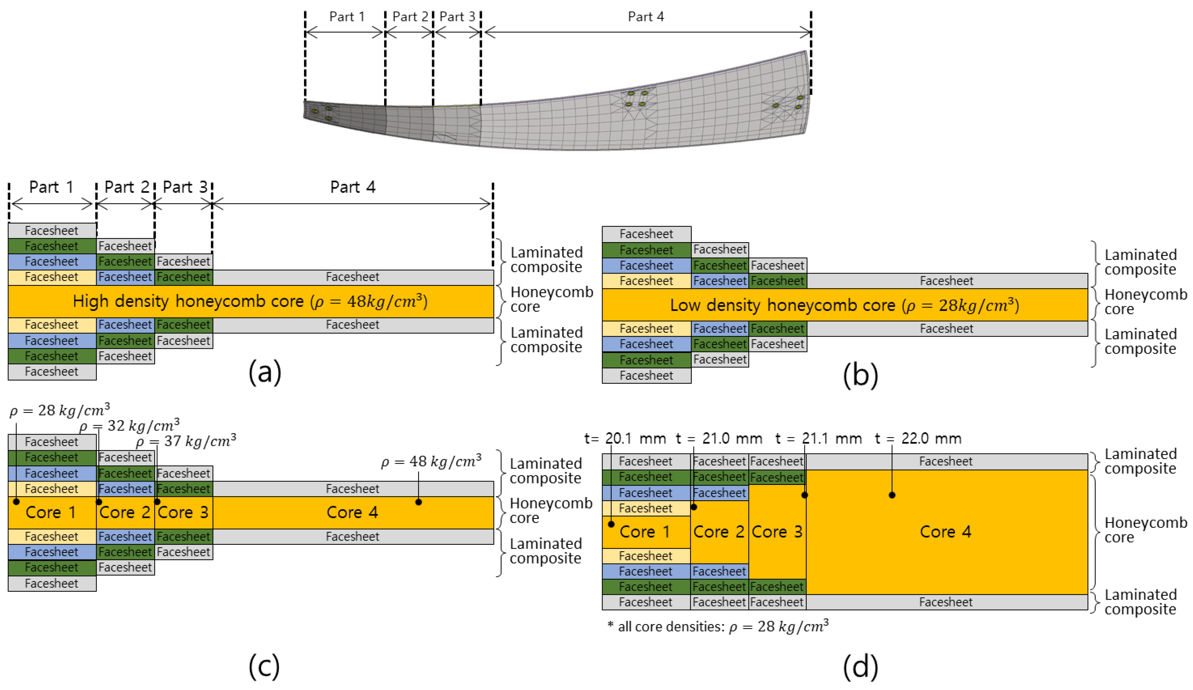
In the previous subsection, the structural performance of the unit structure of the main reflector was investigated with respect to the laminated pattern of the facesheet. The stacking angle of a facesheet wrapped around the honeycomb core was selected as Case 1.1 of [0/45]. As shown in Figure 2, the honeycomb core can be divided into four parts to determine the distribution of the honeycomb core. Because the maximum stress during the operating condition is generated at the root part of the main reflector of the deployed main reflector, the honeycomb core in Part 1 is wrapped with eight plies on the top and bottom. Part 4 is the outer part of the main reflector covered with two plies on the top and bottom. The thickness of the honeycomb core is 16 mm. Figure 2 show four different designs; (Case 2.1) applying a relatively high-density core uniformly to the main reflector; (Case 2.2) applying a relatively low-density core uniformly to the main reflector; (Case 2.3) applying cores with different densities to each of the four parts of the main reflector; and (Case 2.4) applying cores with different thicknesses to each of the four parts of the main reflector. For each core design, the stacking sequence of Case 1.1 is equally applied to individually evaluate the structural influence of the core shape.
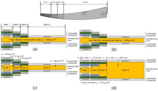
Figure 2.
Stacking sequence of the main reflector consisting of the facesheet with a laminated pattern of Case 1.1 and the material distribution of the honeycomb core of (a) Case 2.1, (b) Case 2.2, (c) Case 2.3, and (d) Case 2.4.
In this subsection, modal analysis is implemented to compare the weight and fundamental mode frequency of the main reflector with the honeycomb core of Case 2.1~Case 2.4. The clamped boundary condition is applied at the hinge point to simulate the deployed condition. The weight and mode frequencies for each case are shown in Table 4. The mode frequencies of Case 2.2 consisting of a low-density core uniformly and Case 2.3 consisting of cores with different densities to each part are relatively higher than those of the other cases. However, in order to manufacture the honeycomb core of Case 2.3, the manufacturing process requires additional steps to interconnect the cores with different densities and it is difficult to maintain the quality of 24 main reflectors manufactured by complex processes. As shown in Table 4, in terms of weight, rigidity, and manufacturability, the design of Case 2.2, which applied a uniform low-density core, is the most suitable honeycomb core for the main reflector.
Table 4.
Modal analysis of the unit structure in the main reflector with respect to each stacking sequence defined in Figure 2.
4. Structural Analysis of Unit Structure of Deployable Reflector Antenna
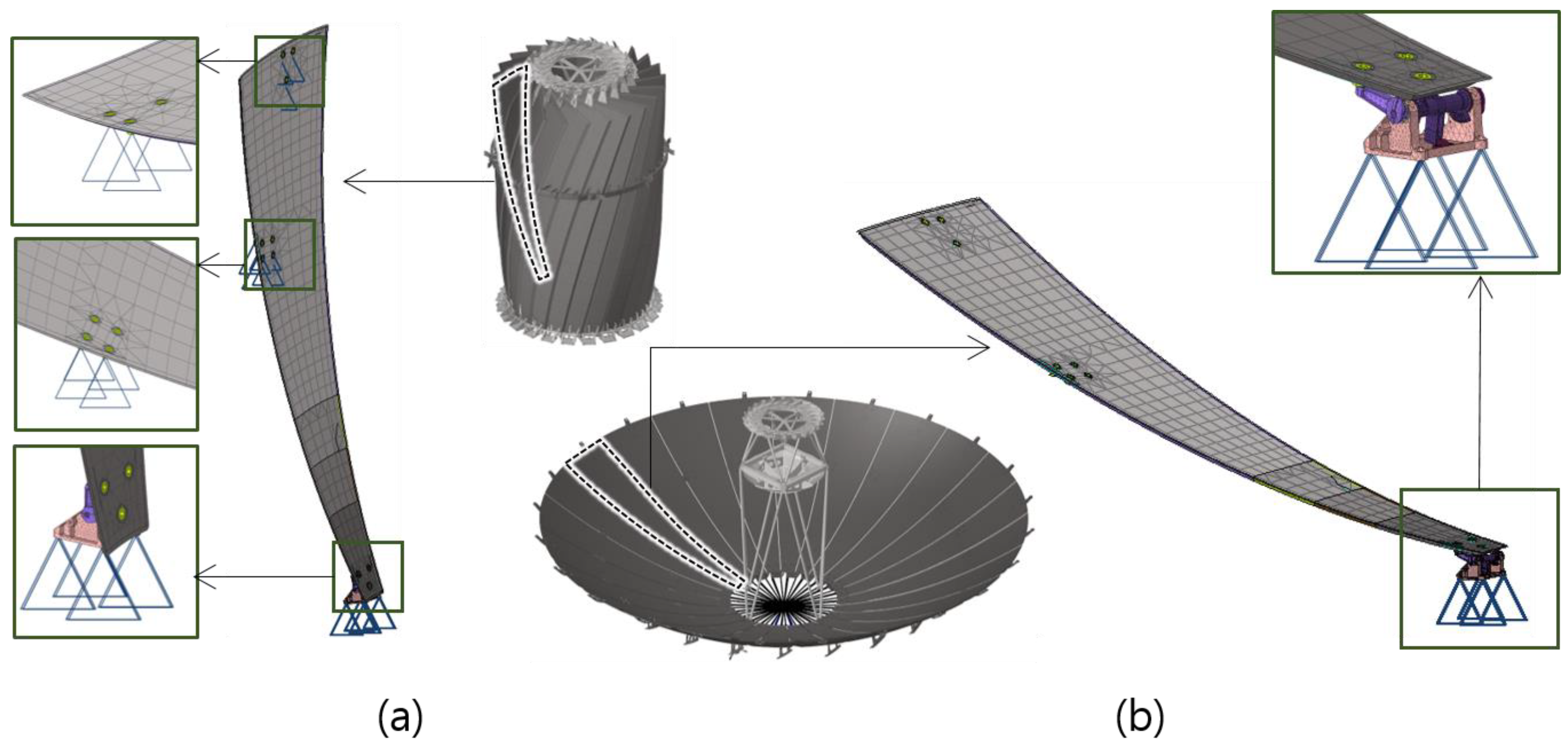
For the unit structure of the main reflector with the stacking sequence in Figure 2c, the modal, quasi-static structural, and thermal-elastic analyses were conducted. To compare relative performance, numerical analyses were performed based on the high-density core of Case 2.1 and the low-density core of Case 2.2. The modal analysis of unit structure in the main reflector is conducted for the stowed and deployed conditions, respectively. For both cases, the clamped boundary condition is applied to the connection point such as a hinge point connected with the antenna system. However, for the stowed condition, the clamped boundary condition is also imposed at the top and middle of the main reflector to account for the hold-and-release mechanism devices as shown in Figure 3a. For the deployed condition, the fixed boundary condition is imposed at only the bottom of the hinge.
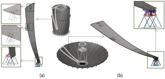
Figure 3.
Boundary Condition of Unit Structure in Deployable Reflector Antenna under (a) the stowed and (b) deployed condition.
First, the quasi-static analysis of the unit structure in the DR-A was conducted under the 0 g condition for the orbital environment and the 1 g condition for the ground environment. The effect of gravity acceleration change on the deformation of the antenna was quantitatively analyzed using quasi-static analysis. The clamped boundary condition was applied at the hinged mechanism to simulate the deployed condition in Figure 3b. Figure 4 shows that the maximum displacement in the z-direction of the reflector was compared to that of the honeycomb core model of Case 2.1 (high-density core) and Case 2.2 (low-density core). As shown in Figure 4, the z-directional maximum displacement of the low-density core structure was m lower than that of the high-density structure. In this viewpoint, the structural stability of gravitational environments of the low-density core model is higher than that of high-density core ones.
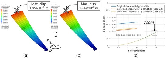
Figure 4.
Quasi-static analysis result with a 1 g gravitational acceleration field; the displacement field of the honeycomb core distribution with (a) high-density and (b) low-density material; (c) contour of displacement.
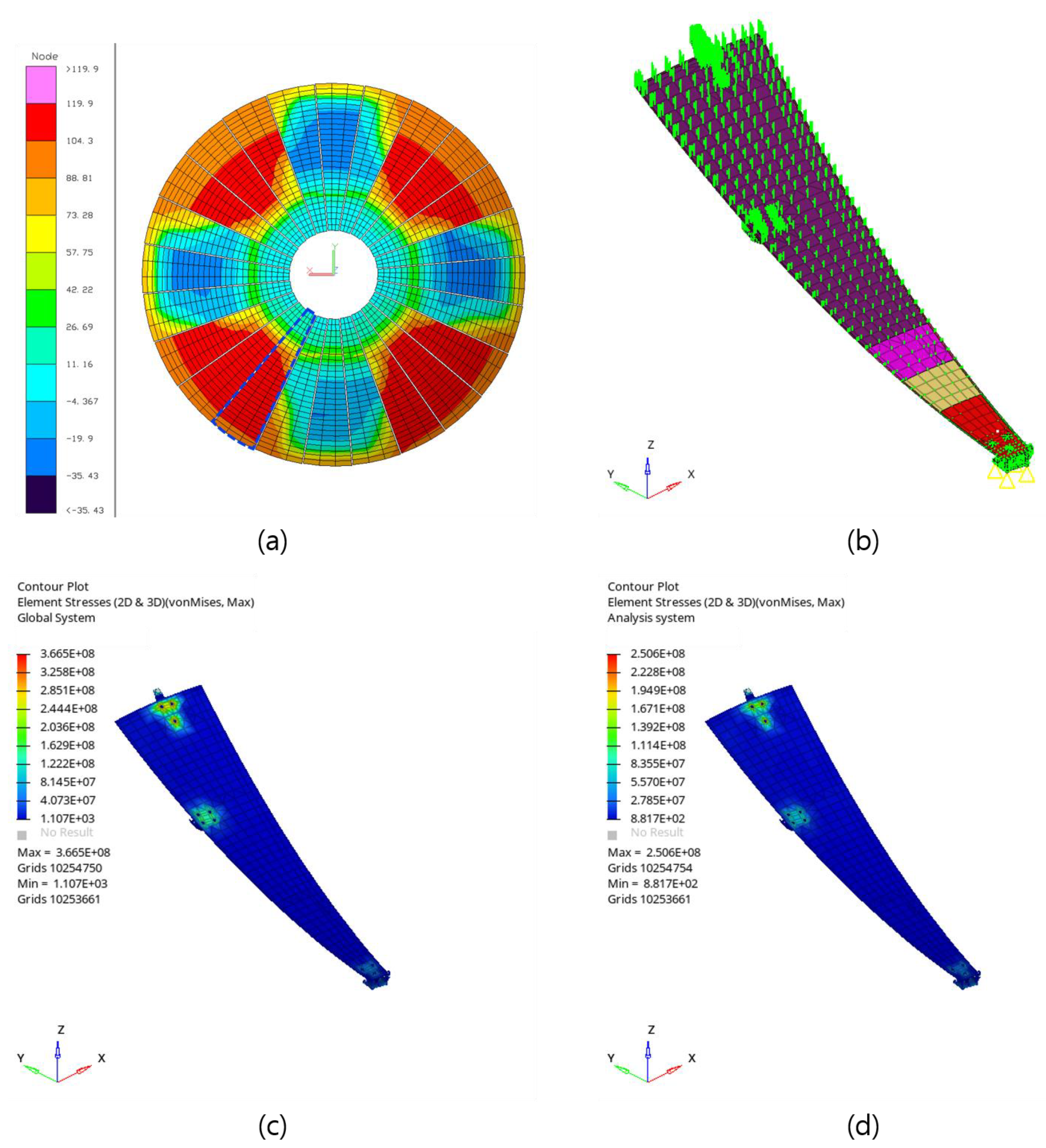
Figure 5 shows the structural–thermal coupled analysis of the unit structure in the DR-A. During mission operation, the satellite is subjected to severe thermal load from low to high temperature, depending on the relative position of the satellite with respect to Earth and Sun. In this study, the worst hot condition where a satellite is located between Earth and Sun is applied to simulate the significant temperature gradient. In order to determine temperature distribution, the orbital thermal analysis for the DR-A is implemented. The temperature distribution for the worst hot case is shown in Figure 5a. The unit structure (blue dotted line) with the highest temperature is applied to the input load for the structural–thermal coupled analysis where the range of the temperature load is from 0 to 110 °C. Stress distributions for high- and low-density models are shown in Figure 5c,d, respectively. The results of the structural–thermal coupled analysis show that the maximum stress of the high-density model is higher than that of the low-density model; the unit structure with the low-density honeycomb core of Case 2.2 is reasonable from the viewpoint of thermal deformation.

Figure 5.
Structural–thermal coupled analysis of the unit structure in the deployable reflector antenna; temperature distribution of the main reflector calculated from (a) orbital thermal analysis for the worst hot case; (b) thermal input of temperature distribution of the unit structure determined by the orbital thermal analysis; stress distribution generated by the thermal gradient of unit structure models for (c) high-density and (d) low-density honeycomb cores.
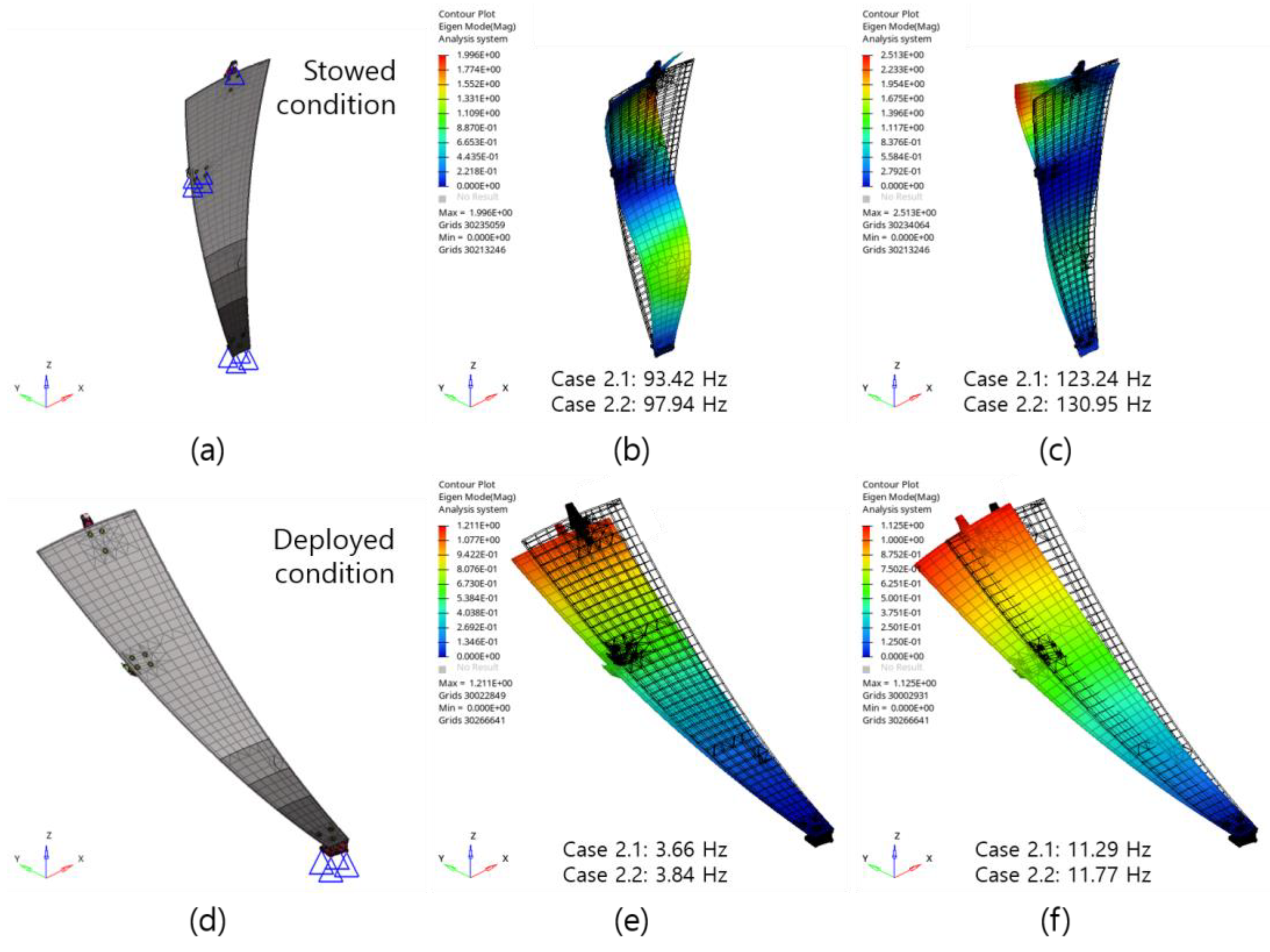
Dynamic stiffness is one of the most important design requirements for a satellite payload such as the antenna. The satellite is subjected to various dynamic loads like acoustic and vibration. In order to prevent the resonance between the primary payload and satellite body, the mode frequency of the primary payload should be sufficiently different from the satellite main body. Thus, all the payloads have a design requirement for dynamic stiffness. Because the configuration of the antenna developed in this paper is an axisymmetric shape of 24 main reflectors, dynamic stiffness of the unit structure can represent the entire structure of the antenna. The modal analysis of the unit structure in the DR-A is implemented to evaluate the dynamic stiffness for the high- and low- density honeycomb core of Cases 2.1 and 2.2. As shown in Figure 6a,d, modal analyses are implemented for the stowed and deployed conditions. Figure 6b,c,e,f show that the first and second mode frequencies of the unit structure with the stacking sequence of Case 2.2 are higher than those of Case 2.1 for the stowed and deployed conditions, and the low-density honeycomb core of Case 2.2 is reasonable from the viewpoint of the dynamic stiffness.
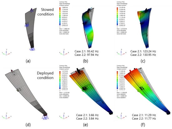
Figure 6.
Modal analysis of the unit structure in the deployable reflector antenna for the stacking sequence of Cases 2.1 and 2.2; (a) triple clamped configuration; (b) 1st and (c) 2nd mode frequencies and shapes under the stowed condition; (d) single clamped configuration; (e) 1st and (f) 2nd mode frequencies and shapes under the deployed condition.
The analysis results of the structural analyses conducted in this study are summarized in Table 5. It was confirmed that Case 2.2 had a weight reduction of approximately 8.8% compared to Case 2.1. Results of the modal analysis results show that all the mode frequencies for the deployed condition satisfy the design requirement for the dynamic stiffness of above 3 Hz (Figure 7). From a thermal and gravitational environment, the performance of the main reflector with low-density cores in Case 2.2 was relatively high than that of the high-density core.
Table 5.
Results of structural analysis for unit structure in main reflector with respect to the type of honeycomb core (HC).
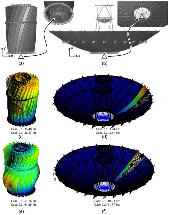
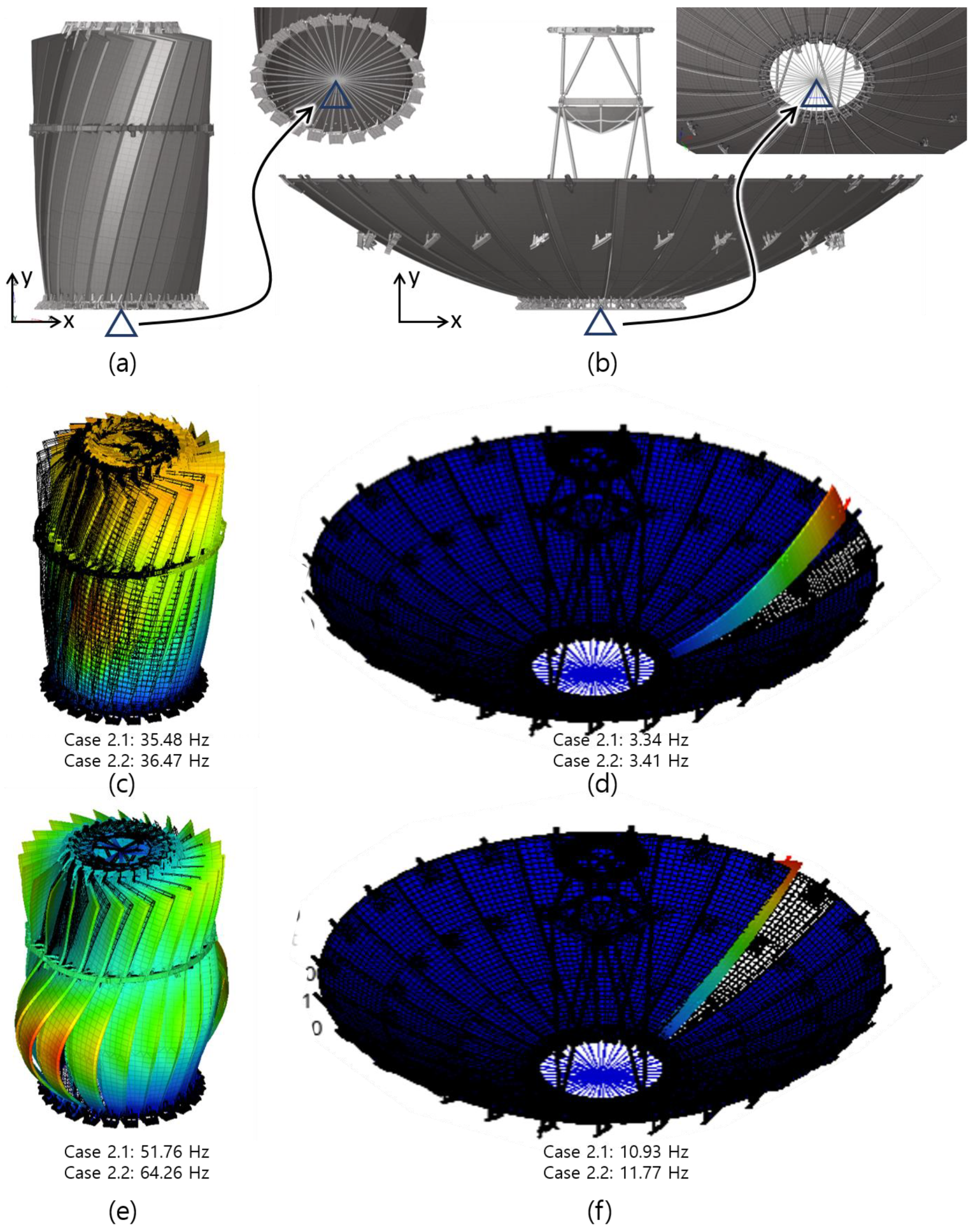
Figure 7.
Mode frequencies and shapes of the deployable reflector antenna assembly under stowed and deployed condition with the high- and low-density cores; finite element configuration under (a) stowed and (b) deployed conditions; mode frequencies and shapes of (b) 1st mode with the stowed condition, 1st mode with the (c) stowed and (d) deployed conditions, 2nd mode with (e) the stowed condition and (f) the deployed condition.
5. Structural Analysis of the Full Model of Deployable Reflector Antenna
In this section, the finite element analysis of the DR-A assembly consisting of a total of 24 petals is performed using the material properties and stacking sequence. The unit structure applied to the antenna assembly is assumed to be two cases, Case 2.1 and Case 2.2. Both antenna models satisfy the weight requirement of the primary payload (less than 110 kg) including the other antenna components. Modal and quasi-static analyses are performed for the antenna assembly composed of 24 main reflectors under the deployed condition. In order to evaluate the effect of the attitude control during the mission operation, the transient analysis of the deployed antenna assembly is implemented.
The modal analyses of satellite assembly under the stowed and deployed conditions are conducted for the launch and on-orbit environments, respectively. The finite element model and boundary conditions are shown in Figure 7a,b. In the case of the deployed condition, the local vibrating modes are individually generated at all unit structures. Thus, the first and second mode of the deployed antenna assembly in Figure 7d,f are the same as those of the unit structure shown in Figure 6d,f, whereas the mode frequencies of the antenna assembly under the stowed mode in Figure 7c,e are lower than those of the unit structure. This is because the vibrating mode is determined by the strut assembly as well as the dynamic stiffness of the main reflector. Although the vibrating mode is partially different from the unit structure, the fundamental mode of both cases satisfies the stiffness requirements for the stowed (≥33 Hz) and deployed conditions (≥3 Hz) [16]. Also, the mode frequency with the main reflector applied with the stacking sequence of Case 2.2 has a relatively high natural frequency, because the model with the low-density core material has a higher weight reduction rate than stiffness reduction, leading to higher natural frequency.
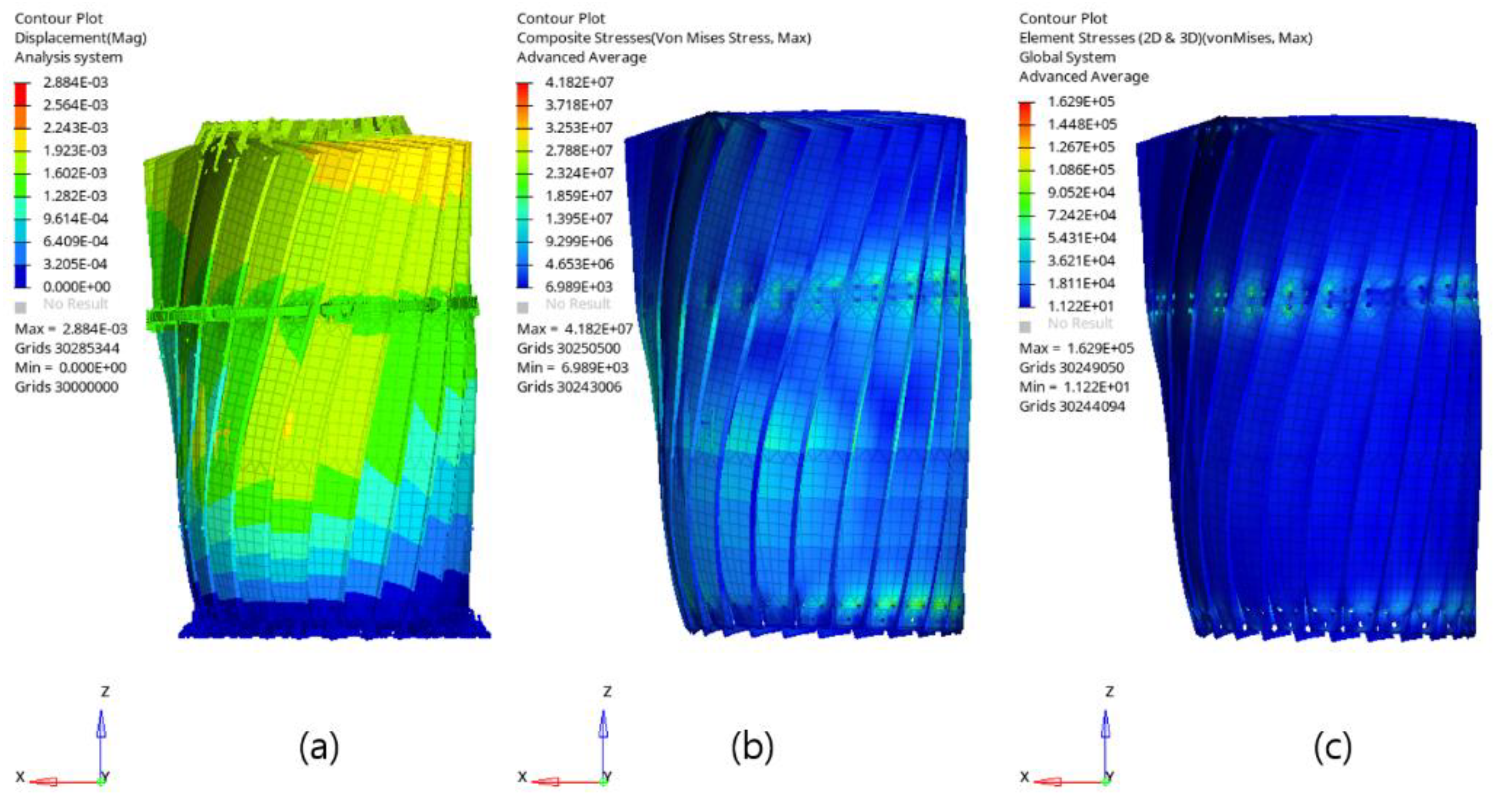
As mentioned above, the satellite is exposed to various dynamic loads during the launch process and the structural safety for sinusoidal vibration in the low-frequency band (below 100 Hz) can be evaluated by quasi-static analysis. In this paper, the dynamic load during the launch process can be simulated as quasi-static loads (x, y, z Combination Load (=15 g)). The results of the quasi-structural analysis are shown in Table 6 and Figure 8. As shown in Table 6, the antenna assembly applied with the main reflector consisting of the low-density core (Case 2.2) has relatively high MOS for the quasi-static loading condition. Compared with the MOS for each direction of the carbon fiber and the honeycomb, the MOS for the one-directional compression load of the carbon fiber composite facesheet is the lowest, indicating that if the actual quasi-static load is applied heavily, failure is likely to occur due to the behavior of the carbon fiber composite facesheet in one-directional compression. The margin of safety (MOS) is shown as follows:
where and are the allowable stress and safety factor, respectively.
Table 6.
Quasi-static analysis and margin of safety (MOS) for the antenna model with high- (Case 2.1) and low-density honeycomb cores.
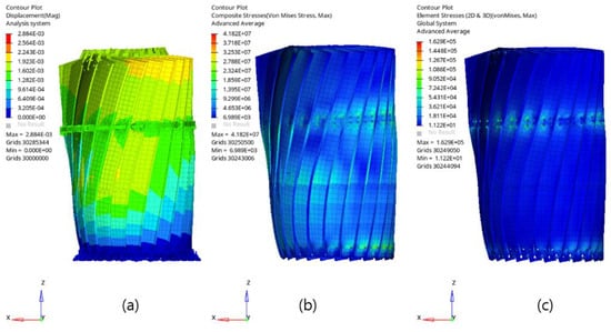
Figure 8.
(a–c) Result of quasi-static analysis for the antenna model in the deployed condition with a low-density core (Case 2.2).
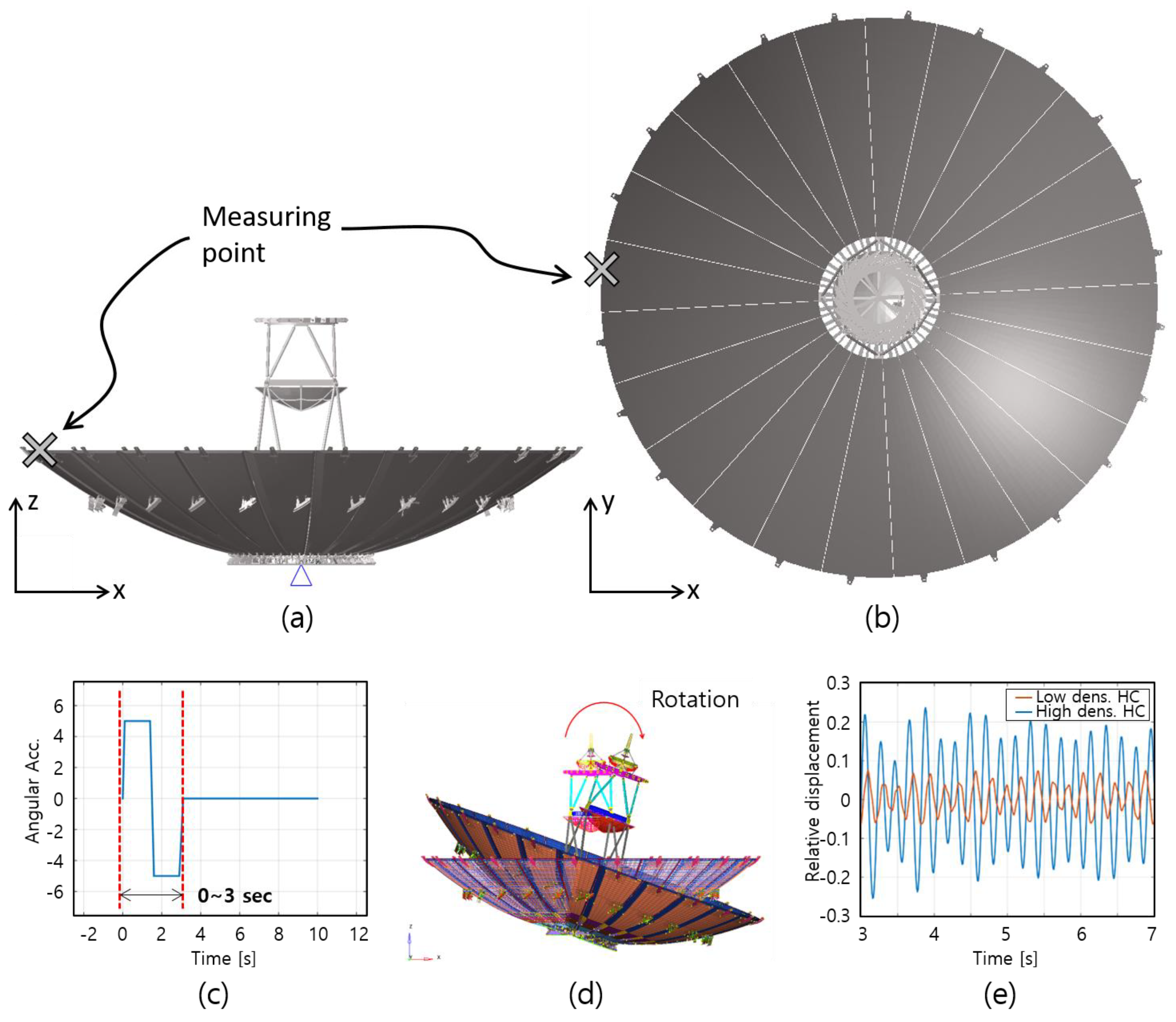
Figure 9 shows the results of the maneuver analysis of the deployed antenna assembly. During the orbit operation in which the satellite may require spotlight shooting for a specific area [19], the high performance for the attitude control is required. For satellite imaging, right after the satellite’s beam angle changes, the satellite rapidly stops and the antenna assembly exhibits a transient response called the pre-image maneuver. With the pre-image maneuver, the transient vibrational response is shown in the main reflector of the antenna assembly. In this regards, the transient analyses to evaluate the effect of micro-vibration for the stacking sequences of Case 2.1 and Case 2.2 of the antenna assembly with each stacking sequence are implemented. Transient analysis is conducted to evaluate the displacement at the end of the tip shown in Figure 9b. The acceleration input function is shown in Figure 9c determined by the Bang-Bang profile [20]. The satellite moves in the (+) direction for 0.5 s, the (−) direction for 1.5 s, and then stops for 0.5 s after moving in the (−) direction. As shown in Figure 9e, vibration reduction in the deployed antenna assembly with the stacking sequence of Case 2.2 is faster than that of the stacking sequence of Case 2.1. The displacement for dynamic behavior is calculated using Equation (2), and the damping ratio for dynamic behavior is inversely proportional to mass and stiffness, as shown in Equation (3). Case 2.2 has a higher damping ratio compared to Case 2.1, as the mass reduction ratio is higher than the stiffness increase ratio, resulting in a decrease in the RMS value for dynamic behavior. The RMS value for the z-direction displacement at the moment of satellite attitude stabilization is m for the Case 2.1 model with a high-density core and m for the Case 2.2 model with a low-density core, indicating that the model with a low-density core has an about 25% better damping performance in terms of RMS displacement criteria. By applying a petal with high damping performance, the time required to stabilize the vibration occurring after high dynamics can be shortened, and additional image acquisition time and shooting frequency can be secured, thus improving the performance of the satellite.
where , , , and mean the fundamental natural frequency, damping ratio, mass, and stiffness, respectively. Also, , , and mean the acceleration, velocity, and displacement of this system.
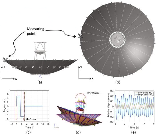
Figure 9.
Transient analysis of the antenna assembly with the stacking sequence of Cases 2.1 and 2.2; (a) finite analysis model and (b) displacement measuring point; (c) acceleration input function; (d) dynamic response on the antenna assembly at 3 s; (e) relative displacement response of two models.
The structural analysis results of the antenna assembly are summarized in Table 6. Regardless of the honeycomb core type, all the cases satisfy the weight requirement (110 kg or less). However, in the case of the antenna assembly consisting of low-density core material (Case 2.2), the total weight of the antenna assembly decreased by approximately 5.7% compared to the high-density core material (Case 2.1). Although the low-density core used in this study has mechanical properties approximately 50% lower than the high-density core, the application of a low-density honeycomb core has better stiffness-to-mass performance than the high-density honeycomb core. Furthermore, as the weight of the structure decreased, the load applied to the structure by gravity decreased, and the dynamic characteristics improved, resulting in improved structural performance for static loads, thermal loads, and dynamic loads.
Table 7 shows the performance comparison between two models with stacking sequences of Case 2.1 (using the high-density honeycomb core) and Case 2.2 (using the low-density honeycomb core). The results of numerical analysis show that the DR-A model with Case 2.2 is lighter and has higher dynamic stiffness than Case 2.1. Therefore, this reflector antenna must be manufactured by applying the main reflector using the stacking pattern of Case 2.2.
Table 7.
Summary of the structural analyses of the antenna assembly level.
6. Conclusions
In this paper, the composite main reflector of the large deployable high-stability reflector antenna was developed using space-grade high-stiffness carbon fiber and the aramid honeycomb core. First of all, the laminated pattern composed of the composite facesheet and the honeycomb core in the main reflector was determined using modal analysis of the unit structure. The weight of the main reflector model using a low-density honeycomb core was reduced by about 8.8% compared to that of the high-density core. The antenna assembly using the low-density core is approximately 5.7% lighter than that using the high-density honeycomb core. Considering the launch and on-orbit environment, the antenna assembly with the low-density core of Case 2.2 has a 25% better damping performance than the high-density core of Case 2.1 in terms of RMS displace criteria. Although the fundamental mode frequency of both models is higher than the stiffness requirement (≥2.5 Hz), the antenna assembly based on Case 2.2 has a 3.7% higher mode frequency than Case 2.1. The DR-A model will be developed based on the main reflector designed in this study. Finally, the environment test of the antenna assembly manufactured by the domestic technology will be performed to experimentally evaluate structural and thermal stability.
Author Contributions
Conceptualization, Y.-J.Y.; methodology, D.-G.K.; software, H.-G.K. and D.-G.K.; validation, H.-G.K. and D.-G.K.; formal analysis, D.-G.K.; investigation, H.-G.K.; resources, Y.-J.Y.; data curation, R.-H.D. and D.-G.K.; writing—original draft preparation, H.-G.K. and D.-G.K.; writing—review and editing, K.-R.K.; visualization, H.-G.K.; supervision, K.-R.K.; project administration K.-R.K.; funding acquisition, K.-R.K. All authors have read and agreed to the published version of the manuscript.
Funding
This study was conducted with support from the Korea Research Institute for defense Technology planning and advancement and the Defense Acquisition Program Administration in 2021 (20-207-B00-011-001).
Institutional Review Board Statement
Not applicable.
Informed Consent Statement
Not applicable.
Data Availability Statement
All data are in the paper; there are no additional data.
Conflicts of Interest
The authors declare no conflict of interest.
References
- Paulis, F.; Giuliomaria, D.D.; Fina, A.; Amici, M.; Mannocchi, G.; Carlofelice, A.D.; Fiaschetti, A.; Tognolatti, P.; Orlandi, A. Highly Integrated Wideband Transmit/Receive Module for X-Band SAR Applications. Appl. Sci. 2023, 13, 801. [Google Scholar] [CrossRef]
- Nasirzadehdizaji, R.; Sanli, F.B.; Abdikan, S.; Cakir, Z.; Sekertekin, A.; Ustuner, M. Sensitivity Analysis of Multi-Temporal Sentinel-1 SAR Parameters to Crop Height and Canopy Coverage. Appl. Sci. 2019, 9, 655. [Google Scholar] [CrossRef]
- Xia, Z.; Jin, S.; Yue, F.; Yang, J.; Zhang, Q.; Zhao, Z.; Zhang, C.; Gao, W.; Zhang, T.; Zhang, Y.; et al. A Novel Space-Borne High-Resolution SAR System with the Non-Uniform Hybrid Sampling Technology for Space Targets Imaging. Appl. Sci. 2022, 12, 4848. [Google Scholar] [CrossRef]
- Zhao, H.; Hao, Z.; Liu, W.; Ding, J.; Sun, Y.; Zhang, Q.; Liu, Y. The shock environment prediction of satellite in the process of satellite-rocket separation. Acta Astronaut. 2019, 159, 112–122. [Google Scholar] [CrossRef]
- Rizzo, F.; Franco, A.; Bonati, A.; Maddaloni, G.; Caterino, N.; Occhiuzzi, A. Predictive analyses for aerodynamic investigation of curtain walls. Structures 2021, 29, 1059–1077. [Google Scholar] [CrossRef]
- Dennison, J.R.; Hartley, K.; Phillipps, L.M.; Dekany, J.; Dyer, J.S.; Johnson, R.H. Small Satellite Space Environments Effects Test Facility. In Proceedings of the 28th Annual AIAA/USU Conference on Small Satellite, Logan, UT, USA, 4–7 August 2014. [Google Scholar]
- Cho, M.; Masui, H.; Hatamura, T.; Date, K.; Horii, S.; Obata, S. Overview of the Nano-satellite Environmental Test Standardization: Test Campaign and Standard Draft, SSC12-VII-10. In Proceedings of the 26th Annual AIAA/USU Conference on Small Satellites, Logan, UT, USA, 13–16 August 2012. [Google Scholar]
- Koo, K.-R.; Kim, H.-G.; Kim, D.-G.; Kwon, S.-C.; Oh, H.-U. Lightweight Design for Active Small SAR S-STEP Satellite Using Multilayered High-Damping Carbon Fiber-Reinforced Plastic Patch. Aerospace 2023, 10, 774. [Google Scholar] [CrossRef]
- Zhao, X.; Zhao, C.; Li, J.; Guan, Y.; Chen, S.; Zhang, L. Research on Design, Simulation, and Experiment of Separation Mechanism for Micro-Nano Satellites. Appl. Sci. 2022, 12, 5997. [Google Scholar] [CrossRef]
- Kim, H.-G.; Kwon, S.-C.; Koo, K.-R.; Song, S.-C.; Yu, Y.; Song, Y.; Park, Y.-H.; Oh, H.-U. Performance Investigation of Superplastic Shape Memory Alloy-Based Vibration Isolator for X-Band Active Small SAR Satellite of S-STEP under Acoustic and Random Vibration Environments. Aerospace 2022, 9, 642. [Google Scholar] [CrossRef]
- Angevain, J.; Ihle, A.; Rodrigues, G.; Santiago-Prowald, J. Present Status and Future Outlook of the Large Deployable Space Borne Reflector Antennas in Europe. In Proceedings of the 3rd International Conference, Tbilisi, Georgia, 19–21 September 2018. [Google Scholar]
- Datashvili, L.; Maghaldadze, N.; Friemel, M.; Luo, T.; Rocha-Schmidt, L.D.; Cappellin, C.; Lasson, J.R.; Jørgensen, R.; Angevain, J.; Ihle, A.; et al. Large deployable reflectors: Enhancing the mesh reflector RF performances. In Proceedings of the 3rd International Conference “Advanced Lightweight Structures and Reflector Antennas”, Tbilisi, Georgia, 19–21 September 2018. [Google Scholar]
- Snyder, J.F.; Wong, E.L.; Hubbard, C.W. Evaluation of Commercially Available Carbon Fibers, Fabrics, and Papers for Potential Use in Multifunctional Energy Storage Applications. J. Electrochem. Soc. 2009, 156, A215–A224. [Google Scholar] [CrossRef]
- Euro-Composites. Mechanical Properties of ECK Honeycomb. 2010. Available online: https://www.nzcomposites.com/site/nzcomposites/ECK%20Honeycomb%20Properties.pdf (accessed on 13 December 2023).
- Contu, S.; Meschini, A.; Rigato, R. Development status of Large Reflectors at TAS-I. In Proceedings of the IEEE Indian Conference on Antennas and Propogation (InCAP), Jaipur, Rajasthan, India, 19–22 December 2019. [Google Scholar]
- Schmid, M.; Barho, R. Development Summary and Test Results of a 3 Meter Unfurlable CFRP Skin Antenna Reflector. In Proceedings of the 10th European Space Mechanisms and Tribology Symposium, San Sebastián, Spain, 20—24 September 2021. [Google Scholar]
- Andrew, Q. Design Allowables Re-evaluation of Ten Composite Materials; Mechanical Testing and Porosity Examination of M55J Fabric Coupons”, Space Systems/Loral, June, 2013. Available online: https://digitalcommons.calpoly.edu/matesp/61 (accessed on 13 December 2023).
- Jones, R.M. Mechanics of Composite Materials; Scientific & Technical Conference; McGraw-Hill: New York, NY, USA, 1975. [Google Scholar]
- Kim, S.; Song, C.-M.; Lee, S.-H.; Song, S.-C.; Oh, H.-U. Design and Performance of X-Band SAR Payload for 80 kg Class Flat-Panel-Type Microsatellite Based on Active Phased Array Antenna. Aerospace 2022, 9, 213. [Google Scholar] [CrossRef]
- Lavigne, L.; Cazaurang, F.; Maini, M.; Zerar, M. Satellite Path Planning by Flatness Approach. Int. Rev. Aerosp. Eng. 2009, 2, 123–132. [Google Scholar]

Disclaimer/Publisher’s Note: The statements, opinions and data contained in all publications are solely those of the individual author(s) and contributor(s) and not of MDPI and/or the editor(s). MDPI and/or the editor(s) disclaim responsibility for any injury to people or property resulting from any ideas, methods, instructions or products referred to in the content. |
© 2024 by the authors. Licensee MDPI, Basel, Switzerland. This article is an open access article distributed under the terms and conditions of the Creative Commons Attribution (CC BY) license (https://creativecommons.org/licenses/by/4.0/).