
Finite Element Analysis of Mandibular Advancement Comparing Hunsuck/Epker and a Novel Modification of the Low Z Plasty Technique of BSSO


Abstract
1. Introduction
2. Materials and Methods
2.1. The Inclusion Criteria for CT Data
- -
- Skeletal II mandibular retrognathism that required mandibular advancement surgery;
- -
- Facial symmetry;
- -
- Not previously treated with orthognathic surgery.
2.2. Finite Element Model
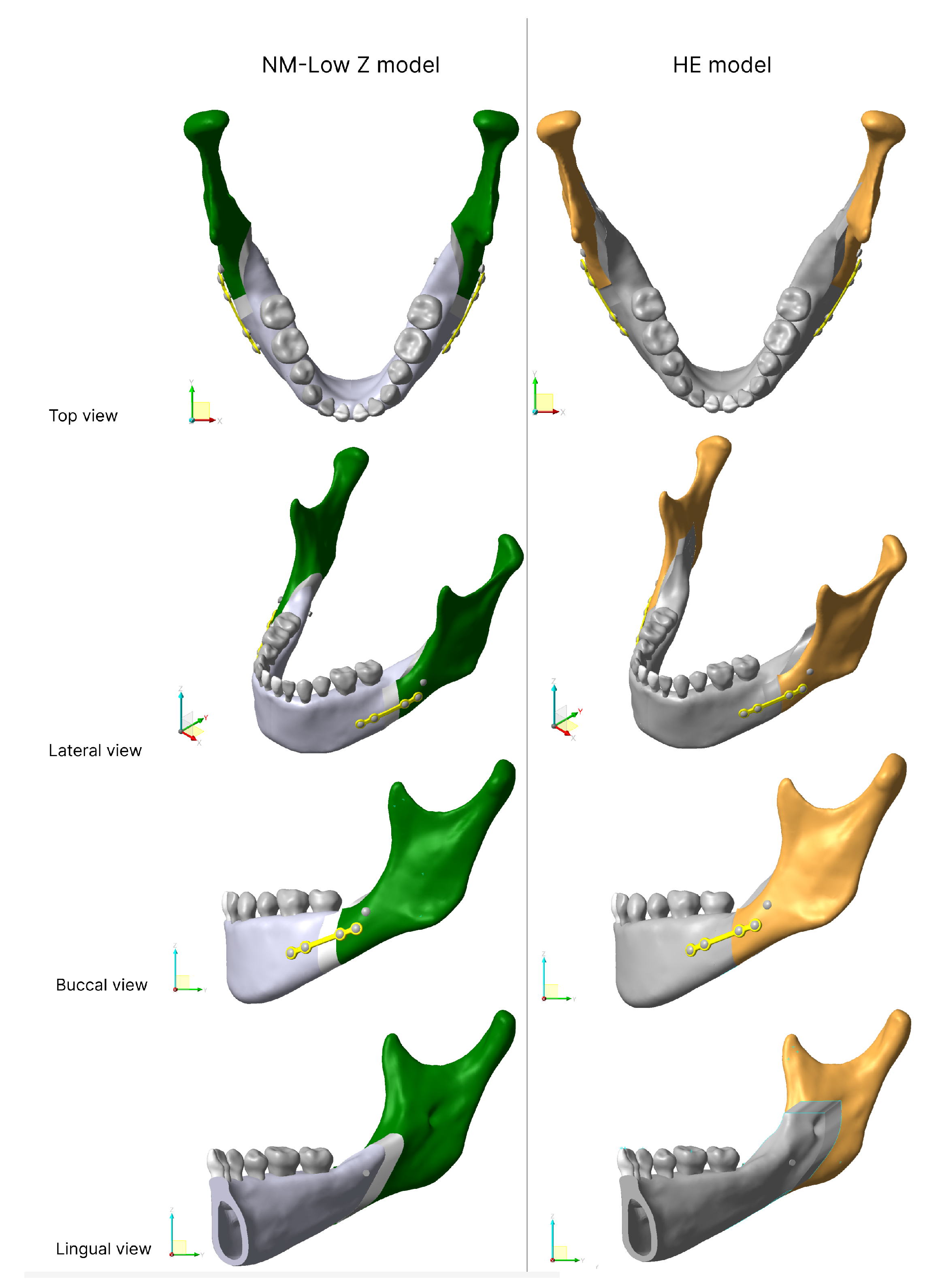
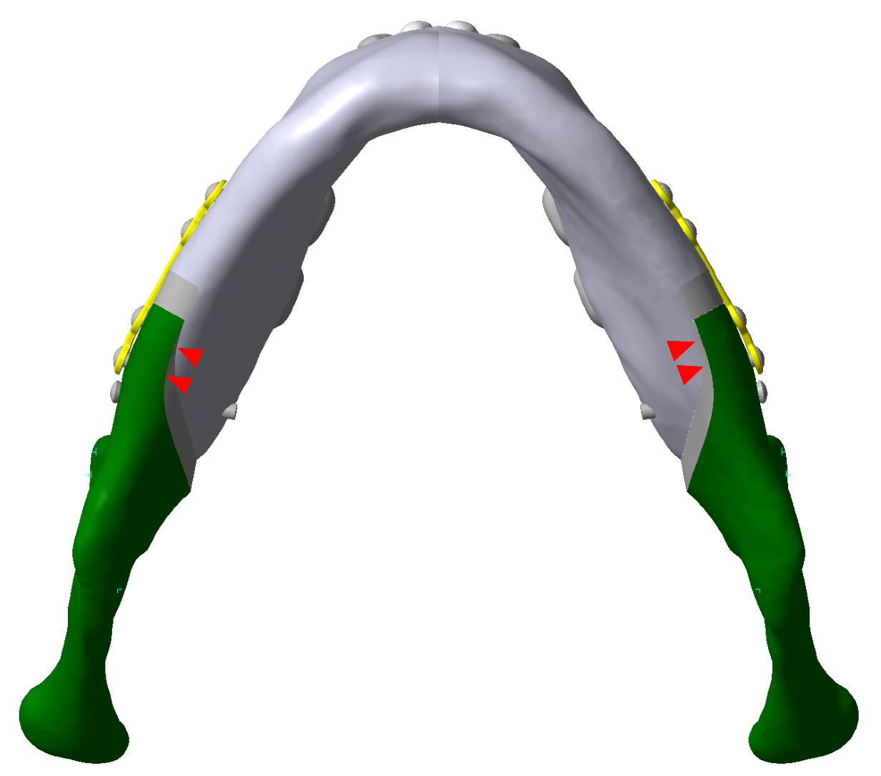
2.2.1. Osteotomy Line
- -
- The HE osteotomy line started with a short horizontal lingual cut just superior to the lingula. The buccal vertical cut was distal to the second molar running down to the mandibular notch anterior to the insertion point of the masseteric muscle.
- -
- The NM-Low Z osteotomy started from a horizontal line stretched 6–7 mm posteriorly and inferiorly from the most superior point of the retromolar triangle. The sagittal cut was made from the tip of the triangle, laterally along the external oblique ridge, to the buccal alveolar bone between first and second mandibular molars then down through the inferior border to create a vertical cut [7]. The osteotomy line of both models are shown in Figure 1.
2.2.2. Advancement and Model Fixation
2.2.3. Mesh Generation
2.3. Material Properties
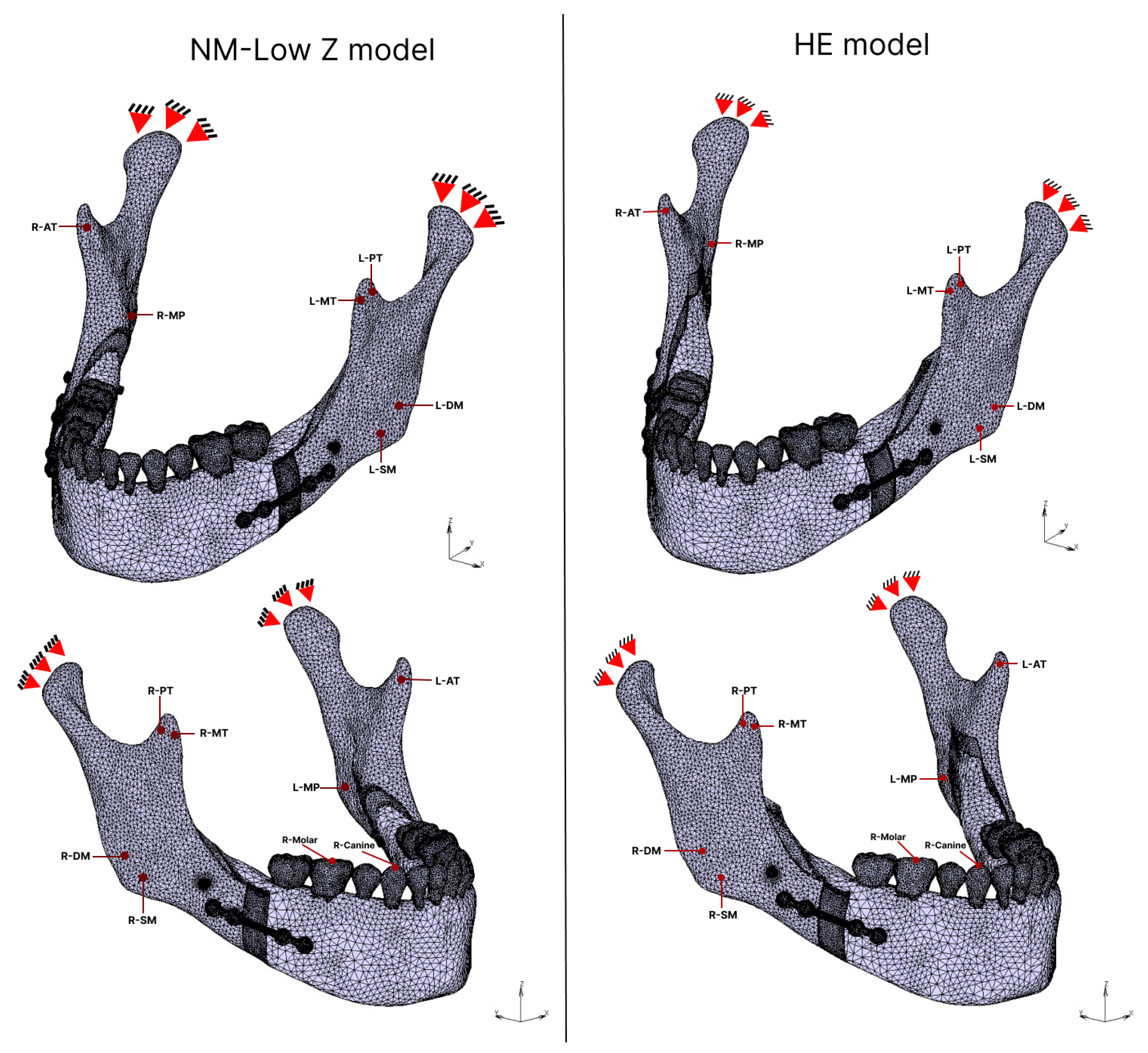
2.4. Boundary Conditions
2.4.1. Muscular Force
2.4.2. Bite Force
2.5. Contact Condition
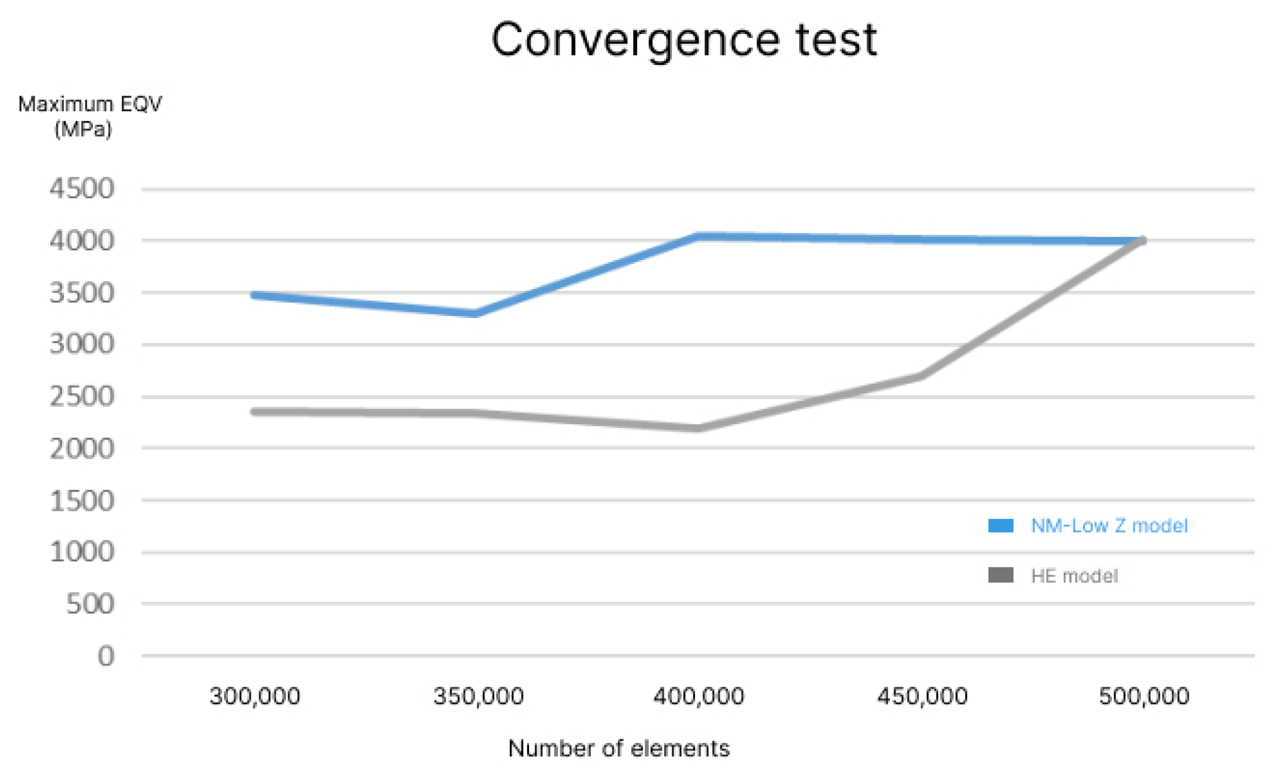
2.6. Element Generation and Convergence Test
3. Results
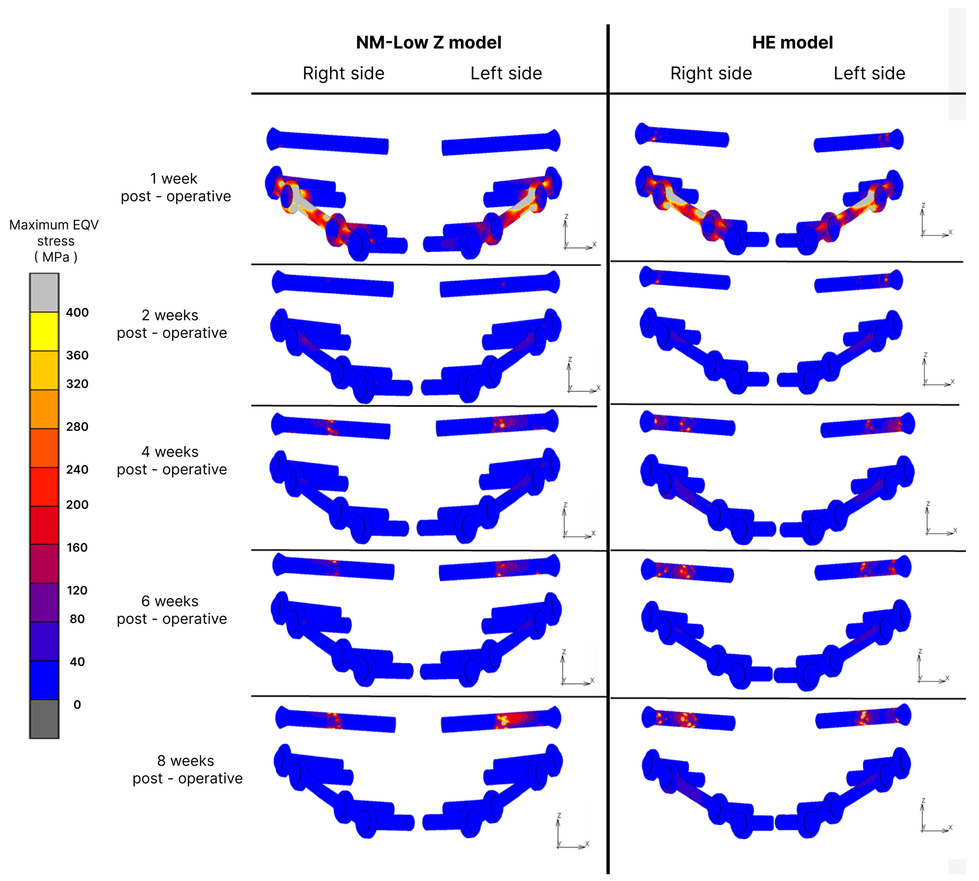
3.1. Fixation Stress
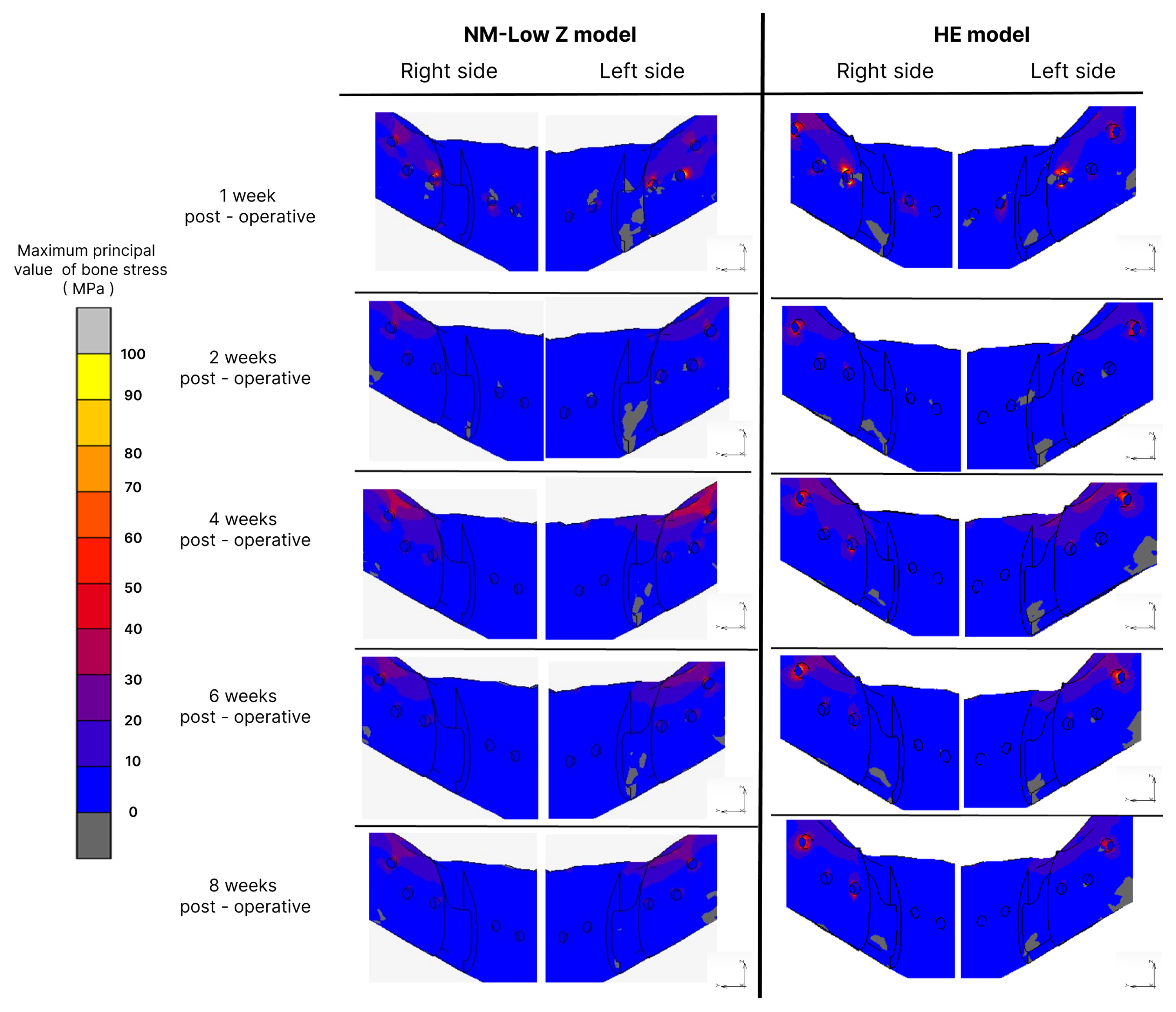
3.2. Bone Stress
3.3. Elastic Strain
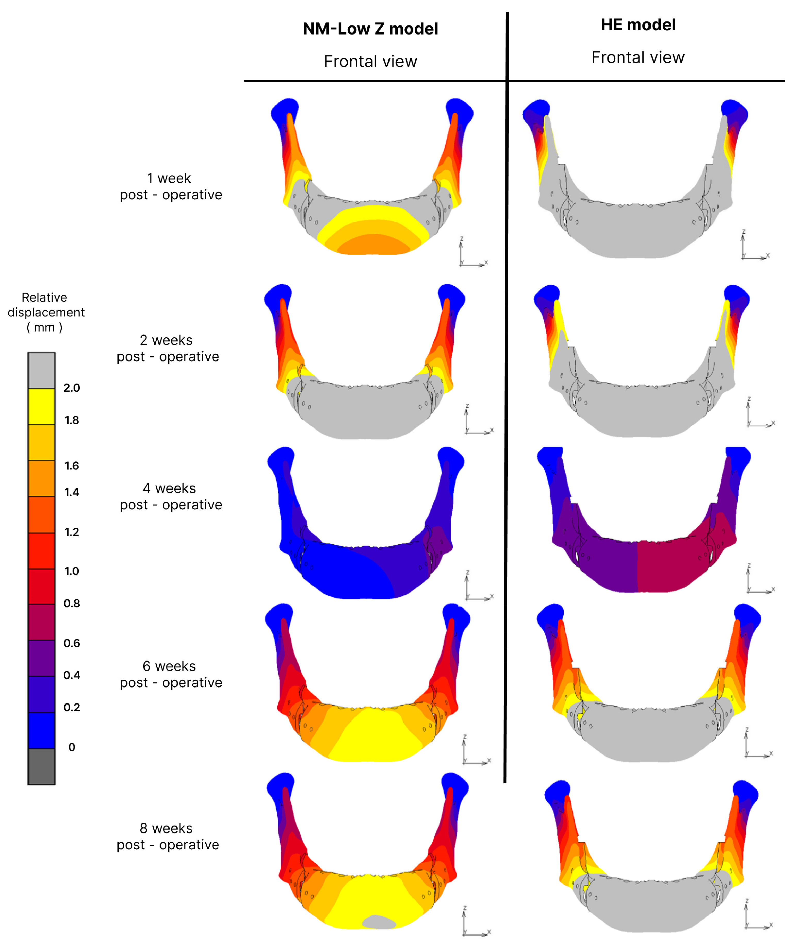
3.4. Displacement
4. Discussion
5. Conclusions
Author Contributions
Funding
Institutional Review Board Statement
Informed Consent Statement
Data Availability Statement
Acknowledgments
Conflicts of Interest
References
- Schwartz, K.; Rodrigo-Domingo, M.; Jensen, T. Skeletal Stability after Large Mandibular Advancement (>10 mm) with Bilateral Sagittal Split Osteotomy and Skeletal Elastic Intermaxillary Fixation. J. Oral Maxillofac. Res. 2016, 7, e5. [Google Scholar] [CrossRef]
- Böckmann, R.A. Modification of the Mandibular Split Based on a Physical Model: Experimental Animal and Clinical Studies. Ph.D. Thesis, Maastricht University, Maastricht, The Netherlands, 2017. [Google Scholar]
- Obwegeser, H.L. Orthognathic surgery and a tale of how three procedures came to be: A letter to the next generations of surgeons. Clin. Plast. Surg. 2007, 34, 331–355. [Google Scholar] [CrossRef]
- Monson, L.A. Bilateral sagittal split osteotomy. Semin. Plast. Surg. 2013, 27, 145–148. [Google Scholar] [CrossRef]
- Böckmann, R.; Meyns, J.; Dik, E.; Kessler, P. The modifications of the sagittal ramus split osteotomy: A literature review. Plast. Reconstr. Surg. Glob. Open 2014, 2, e271. [Google Scholar] [CrossRef]
- Verweij, J.P.; Houppermans, P.N.; Gooris, P.; Mensink, G.; van Merkesteyn, J.P. Risk factors for common complications associated with bilateral sagittal split osteotomy: A literature review and meta-analysis. J. Craniomaxillofac. Surg. 2016, 44, 1170–1180. [Google Scholar] [CrossRef]
- Chaiprakit, N.; Oupadissakoon, C.; Klaisiri, A.; Patchanee, S. A Surgeon-Friendly BSSO by the Novel Modification of Low Z Plasty: Approach Focus and Case Report: A Case Report. J. Int. Dent. Med. Res. 2021, 14, 768–772. [Google Scholar]
- Dumrongwanich, O.; Chantarapanich, N.; Patchanee, S.; Inglam, S.; Chaiprakit, N. Finite element analysis between Hunsuck/Epker and novel modification of Low Z plasty technique of mandibular sagittal split osteotomy. Proc. Inst. Mech. Eng. H 2022, 236, 646–655. [Google Scholar] [CrossRef] [PubMed]
- Takahashi, H.; Moriyama, S.; Furuta, H.; Matsunaga, H.; Sakamoto, Y.; Kikuta, T. Three lateral osteotomy designs for bilateral sagittal split osteotomy: Biomechanical evaluation with three-dimensional finite element analysis. Head Face Med. 2010, 6, 4. [Google Scholar] [CrossRef] [PubMed]
- Saghafi, H.; Benington, P.; Ayoub, A. Impact of orthognathic surgery on quality of life: A comparison between orthodontics-first and surgery-first approaches. Br. J. Oral Maxillofac. Surg. 2020, 58, 341–347. [Google Scholar] [CrossRef] [PubMed]
- Thitiyuk, C.; Patchanee, S.; Klaisiri, A.; Chaiprakit, N. Comparison of Orthodontic First and Surgery First Approaches to Quality of Life in Orthognathic Surgery Patients: A Prospective Cohort Study. Appl. Sci. 2022, 12, 12137. [Google Scholar] [CrossRef]
- Tabrizi, R.; Nili, M.; Aliabadi, E.; Pourdanesh, F. Skeletal stability following mandibular advancement: Is it influenced by the magnitude of advancement or changes of the mandibular plane angle? J. Korean Assoc. Oral Maxillofac. Surg. 2017, 43, 152–159. [Google Scholar] [CrossRef]
- Eggensperger, N.; Smolka, W.; Rahal, A.; Iizuka, T. Skeletal relapse after mandibular advancement and setback in single-jaw surgery. J. Oral Maxillofac. Surg. 2004, 62, 1486–1496. [Google Scholar] [CrossRef]
- Sahoo, N.K.; Agarwal, S.S.; Datana, S.; Bhandari, S.K. Long-Term Study of Relapse After Mandibular Orthognathic Surgery: Advancement Versus Setback. J. Maxillofac. Oral Surg. 2022, 21, 469–480. [Google Scholar] [CrossRef] [PubMed]
- Chen, Y.; Zhang, J.; Rao, N.; Han, Y.; Ferraro, N.; August, M. Independent risk factors for long-term skeletal relapse after mandibular advancement with bilateral sagittal split osteotomy. Int. J. Oral Maxillofac. Surg. 2020, 49, 779–786. [Google Scholar] [CrossRef] [PubMed]
- Van den Bempt, M.; Vinayahalingam, S.; Han, M.D.; Bergé, S.J.; Xi, T. The role of muscular traction in the occurrence of skeletal relapse after advancement bilateral sagittal split osteotomy (BSSO): A systematic review. Orthod. Craniofac. Res. 2022, 25, 1–13. [Google Scholar] [CrossRef] [PubMed]
- Epker, B.N.; Wessberg, G.A. Mechanisms of early skeletal release following surgical advancement of the mandible. Br. J. Oral Surg. 1982, 20, 175–182. [Google Scholar] [CrossRef] [PubMed]
- Wessberg, G.A.; Schendel, S.A.; Epker, B.N. The role of suprahyoid myotomy in surgical advancement of the mandible via sagittal split ramus osteotomies. J. Oral Maxillofac. Surg. 1982, 40, 273–277. [Google Scholar] [CrossRef] [PubMed]
- Mobarak, K.A.; Espeland, L.; Krogstad, O.; Lyberg, T. Mandibular advancement surgery in high-angle and low-angle class II patients: Different long-term skeletal responses. Am. J. Orthod. Dentofac. Orthop. 2001, 119, 368–381. [Google Scholar] [CrossRef]
- Shrivastava, N.; Thukral, R.; Garg, A.; Tripathi, A.; Marothiya, S. Stress Pattern and Deformation in Mid-palatal Suture and Posterior Dentoalveolar Area With Two Different Types of Rapid Maxillary Expansion Appliances: A Finite Element Method Study. J. Indian Orthod. Soc. 2021, 55, 278–284. [Google Scholar] [CrossRef]
- Duangrattanaprathip, N.; Rungsiyakull, P.; Rungsiyakull, C.; Suttiat, K. Basic Knowledges of Finite Element Method and Application in Implant Dentistry. Chiang Mai Dent. J. 2018, 39, 29–42. [Google Scholar]
- Erkmen, E.; Simsek, B.; Yucel, E.; Kurt, A. Three-dimensional finite element analysis used to compare methods of fixation after sagittal split ramus osteotomy: Setback surgery-posterior loading. Br. J. Oral Maxillofac. Surg. 2005, 43, 97–104. [Google Scholar] [CrossRef]
- Puricelli, E.; Fonseca, J.S.; de Paris, M.F.; Sant’Anna, H. Applied mechanics of the Puricelli osteotomy: A linear elastic analysis with the finite element method. Head Face Med. 2007, 3, 38. [Google Scholar] [CrossRef]
- Rao, S.H.; Selvaraj, L.; Lankupalli, A.S. Skeletal stability after bilateral sagittal split advancement and setback osteotomy of the mandible with miniplate fixation. Craniomaxillofac. Trauma Reconstr. 2014, 7, 9–16. [Google Scholar] [CrossRef]
- Stringhini, D.J.; Sommerfeld, R.; Uetanabaro, L.C.; Leonardi, D.P.; Araujo, M.R.; Rebellato, N.L.; Costa, D.J.; Scariot, R. Resistance and Stress Finite Element Analysis of Different Types of Fixation for Mandibular Orthognathic Surgery. Braz. Dent. J. 2016, 27, 284–291. [Google Scholar] [CrossRef]
- O’Mahony, A.M.; Williams, J.L.; Spencer, P. Anisotropic elasticity of cortical and cancellous bone in the posterior mandible increases peri-implant stress and strain under oblique loading. Clin. Oral Implant. Res. 2001, 12, 648–657. [Google Scholar] [CrossRef]
- Thote, A.M.; Patil, R.V. Estimation of the maximum permissible intrusive force for intrusion of a canine tooth: One-dimensional finite element study. Mater. Today Proc. 2022, 51, 918–923. [Google Scholar] [CrossRef]
- Ghiasi, M.S.; Chen, J.E.; Rodriguez, E.K.; Vaziri, A.; Nazarian, A. Computational modeling of human bone fracture healing affected by different conditions of initial healing stage. BMC Musculoskelet. Disord. 2019, 20, 562. [Google Scholar] [CrossRef]
- Isaksson, H.; Wilson, W.; van Donkelaar, C.C.; Huiskes, R.; Ito, K. Comparison of biophysical stimuli for mechano-regulation of tissue differentiation during fracture healing. J. Biomech. 2006, 39, 1507–1516. [Google Scholar] [CrossRef] [PubMed]
- Huang, H.L.; Su, K.C.; Fuh, L.J.; Chen, M.Y.; Wu, J.; Tsai, M.T.; Hsu, J.T. Biomechanical analysis of a temporomandibular joint condylar prosthesis during various clenching tasks. J. Craniomaxillofac. Surg. 2015, 43, 1194–1201. [Google Scholar] [CrossRef] [PubMed]
- Gerlach, K.L.; Schwarz, A. Bite forces in patients after treatment of mandibular angle fractures with miniplate osteosynthesis according to Champy. Int. J. Oral Maxillofac. Surg. 2002, 31, 345–348. [Google Scholar] [CrossRef]
- Ghorashi, S.; Keshavarzi, M.; Damercheli, S.; Parhiz, A. The comparison of three different fixation methods on bilateral sagittal split ramus osteotomy mandibular on a 3D of fully modelled mandible by the finite element method. JCR 2019, 6, 113–121. [Google Scholar]
- Melosh, R.J. Finite element analysis convergence curves. Finite Elem. Anal. Des. 1990, 7, 115–121. [Google Scholar] [CrossRef]
- Ayturk, U.M.; Puttlitz, C.M. Parametric convergence sensitivity and validation of a finite element model of the human lumbar spine. Comput. Methods Biomech. Biomed. Eng. 2011, 14, 695–705. [Google Scholar] [CrossRef] [PubMed]
- Ellis, E., 3rd; Esmail, N. Malocclusions resulting from loss of fixation after sagittal split ramus osteotomies. J. Oral Maxillofac. Surg. 2009, 67, 2528–2533. [Google Scholar] [CrossRef]
- Kundu, J.; Pati, F.; Shim, J.H.; Cho, D.W. 10—Rapid prototyping technology for bone regeneration. In Rapid Prototyping of Biomaterials; Narayan, R., Ed.; Woodhead Publishing: Cambridge, UK, 2014; pp. 254–284. [Google Scholar] [CrossRef]
- Feng, X.; Lin, G.; Fang, C.X.; Lu, W.W.; Chen, B.; Leung, F.K.L. Bone resorption triggered by high radial stress: The mechanism of screw loosening in plate fixation of long bone fractures. J. Orthop. Res. 2019, 37, 1498–1507. [Google Scholar] [CrossRef]
- Frost, H.M. A 2003 update of bone physiology and Wolff’s Law for clinicians. Angle Orthod. 2004, 74, 3–15. [Google Scholar] [PubMed]
- Dai, Z.; Hou, M.; Ma, W.; Song, D.L.; Zhang, C.X.; Zhou, W.Y. Evaluation of the Transverse Displacement of the Proximal Segment After Bilateral Sagittal Split Ramus Osteotomy with Different Lingual Split Patterns and Advancement Amounts Using the Finite Element Method. J. Oral Maxillofac. Surg. 2016, 74, 2286.E1–2286.E11. [Google Scholar] [CrossRef]
- Haden, C.V.; Collins, P.C.; Harlow, D.G. Yield Strength Prediction of Titanium Alloys. JOM 2015, 67, 1357–1361. [Google Scholar] [CrossRef]
- Bianchi, A.E.; Dolci, G., Jr.; Sberna, M.T.; Sanfilippo, S. Factors affecting bone response around loaded titanium dental implants: A literature review. J. Appl. Biomater. Biomech. 2005, 3, 135–140. [Google Scholar]
- Steenen, S.A.; van Wijk, A.J.; Becking, A.G. Bad splits in bilateral sagittal split osteotomy: Systematic review and meta-analysis of reported risk factors. Int. J. Oral Maxillofac. Surg. 2016, 45, 971–979. [Google Scholar] [CrossRef] [PubMed]
- Posnick, J.C.; Choi, E.; Liu, S. Occurrence of a ‘bad’ split and success of initial mandibular healing: A review of 524 sagittal ramus osteotomies in 262 patients. Int. J. Oral Maxillofac. Surg. 2016, 45, 1187–1194. [Google Scholar] [CrossRef]
- Posnick, J.C.; Kinard, B.E. Use of a ‘low and short’ medial cut limits sagittal ramus osteotomy interferences. Int. J. Oral Maxillofac. Surg. 2021, 50, 1583–1587. [Google Scholar] [CrossRef]
- Tangarturonrasme, P.; Laddawun, S. Modified bilateral sagittal split osteotomy for correction of severe anterior open bite: Technical note and case report. Chula Med. J. 2016, 60, 45–54. [Google Scholar]

| Model | Material Properties | Young’s Modulus (MPa) | Poisson’s Ratio | Shear Modulus (MPa) |
|---|---|---|---|---|
| Mandible | Cortical bone [8,26] | Ex = Ez = 12,600 Ey = 19,400 | υxy = υzy = 0.25 υyx = υyz = 0.39 υxz = υzx = 0.30 | Gxy = Gyz = 5700 Gxz = 4850 |
| Cancellous bone [8,26] | Ex = Ey = 1148 Ez = 210 | υxy = υyx = 0.32 υxz = υyz = 0.05 υzx = υzy = 0.01 | Gxy = 434 Gyz = Gxz = 68 | |
| Teeth [27] | 19,600 | 0.3 | - | |
| Plate and screws [26] | Unalloyed titanium | 114,000 | 0.3 | - |
| Fracture site [28,29] | Inflammatory stage | 2 | 0.17 | - |
| Soft callus stage (2 weeks) | 1000 | 0.3 | - | |
| Hard callus stage (4–6 weeks) | 6000 | 0.3 | - |
| Muscular Force (N) [30] | |||||||
|---|---|---|---|---|---|---|---|
| Side | Direction | Muscle | |||||
| Right | Force | SM | DM | MP | AT | MT | PT |
| 137.1 | 58.8 | 146.8 | 115.3 | 63.1 | 44.6 | ||
| X | −28.4 | −32.1 | 71.4 | −17.2 | −14 | −9.8 | |
| Y | −57.4 | 21 | −54.8 | −5.1 | 31.5 | 38.1 | |
| Z | 121.2 | 44.5 | 116.1 | 114 | 52.8 | 21.1 | |
| Left | Force | 114.2 | 49 | 104.9 | 91.6 | 64.1 | 29.5 |
| X | 23.6 | 26.7 | −51 | 13.7 | 14.2 | 6.1 | |
| Y | −47.9 | 17.5 | −39.1 | −4 | 32 | 25.2 | |
| Z | 101 | 37.5 | 83 | 90.5 | 53.6 | 14 | |
| Bite Force (N) [31] | |||||||
| Occlusal Loading | Direction | 1 Week Post-Operation | 2 Weeks Post-Operation | 4 Weeks Post-Operation | 6 Weeks Post-Operation | 8 Weeks Post-Operation | |
| Right molar | Z | −72.37 | −94.52 | −192.1 | −130.43 | −130.43 | |
| Right canine | Z | −62.13 | −65.17 | −140.35 | −108.25 | −108.25 | |
| Post-Operative Stage | Osteotomy Technique | Maximum EQV in Plate and Screw (MPa) | Maximum Principal Value of Stress in Bone Vicinity (MPa) | Elastic Strain (µε) | |||
|---|---|---|---|---|---|---|---|
| Rt | Lt | Rt | Lt | Rt | Lt | ||
| Inflammatory stage | NM-Low Z | 1654.36 | 1187.59 | 88.88 | 88.13 | 1208 | 1898 |
| Hunsuck | 1123.6 | 1096.8 | 160.33 | 143.92 | 941.8 | 1396 | |
| 2 weeks post-operation | NM-Low Z | 124.8 | 188.03 | 37.62 | 35.54 | 159 | 67 |
| Hunsuck | 533.99 | 407.25 | 80.33 | 68.9 | 97.8 | 97.3 | |
| 4 weeks post-operation | NM-Low Z | 618.85 | 875.57 | 55.22 | 60.87 | 53.7 | 73.2 |
| Hunsuck | 1032.86 | 1255.75 | 81.07 | 91.54 | 29 | 127 | |
| 6 weeks post-operation | NM-Low Z | 584.67 | 458.32 | 41.69 | 50.47 | 38 | 53.3 |
| Hunsuck | 1102.15 | 1186.33 | 105.22 | 89.65 | 23.3 | 119 | |
| 8 weeks post-operation | NM-Low Z | 803.19 | 1308.69 | 41.74 | 50.11 | 18.7 | 39.6 |
| Hunsuck | 1357.45 | 1456.38 | 86.68 | 79.99 | 24.4 | 74.8 | |
| Post-Operative Stage | Osteotomy Technique | Total Displacement at Point B (mm) | Relative Displacement (mm) | ||
|---|---|---|---|---|---|
| X | Y | Z | |||
| Inflammatory stage | NM-Low Z | 0.024 | −1.63 | 0.789 | 0.28 |
| Hunsuck | −0.314 | −2.855 | 3.731 | 0.14 | |
| 2 weeks post-operation | NM-Low Z | −0.014 | −1.68 | 2.848 | 0.9 |
| Hunsuck | −0.057 | −2.763 | 4.524 | 1.6 | |
| 4 weeks post-operation | NM-Low Z | −0.07 | −0.16 | 0.026 | 0.03 |
| Hunsuck | −0.093 | −0.409 | 0.45 | 0.02 | |
| 6 weeks post-operation | NM-Low Z | −0.037 | −0.98 | 1.578 | 0.4 |
| Hunsuck | −0.063 | −1.673 | 2.658 | 0.83 | |
| 8 weeks post-operation | NM-Low Z | −0.033 | −0.99 | 1.62 | 0.43 |
| Hunsuck | −0.056 | −1.679 | 2.694 | 0.88 | |
| Reference Parameter | Study Parameter | Results | ||
|---|---|---|---|---|
| The yield point of the titanium (MPa) [40] | 720–950 | Range of maximum of EQV in plate and screw (MPa) | NM-Low Z | 124–1654 |
| Hunsuck | 407–1456 | |||
| Erkman et al., 2005 [22] | 4–15 | |||
| Puricelli et al., 2007 [23] | 1.2–1.8 | |||
| Takahashi et al., 2010 [9] | 1124–1939 | |||
| Yield point of cortex bone stress (MPa) [36] | 131–224 | Range of maximum principal value of bone stress (MPa) | NM-Low Z | 35–105 |
| Hunsuck | 68–160 | |||
| Elastic strain (µε) [41] | 200–2000 | Range of elastic strain (µε) | NM-Low Z | 1200–1800 |
| Hunsuck | 900–1300 | |||
| Displacement | Average transverse displacement (mm) | NM-Low Z | 0.036 | |
| Dai et al., 2016 [39] | 4 | |||
Disclaimer/Publisher’s Note: The statements, opinions and data contained in all publications are solely those of the individual author(s) and contributor(s) and not of MDPI and/or the editor(s). MDPI and/or the editor(s) disclaim responsibility for any injury to people or property resulting from any ideas, methods, instructions or products referred to in the content. |
© 2024 by the authors. Licensee MDPI, Basel, Switzerland. This article is an open access article distributed under the terms and conditions of the Creative Commons Attribution (CC BY) license (https://creativecommons.org/licenses/by/4.0/).
Share and Cite
Boonlue, S.; Patchanee, S.; Inglam, S.; Chaiprakit, N. Finite Element Analysis of Mandibular Advancement Comparing Hunsuck/Epker and a Novel Modification of the Low Z Plasty Technique of BSSO. Appl. Sci. 2024, 14, 1795. https://doi.org/10.3390/app14051795
Boonlue S, Patchanee S, Inglam S, Chaiprakit N. Finite Element Analysis of Mandibular Advancement Comparing Hunsuck/Epker and a Novel Modification of the Low Z Plasty Technique of BSSO. Applied Sciences. 2024; 14(5):1795. https://doi.org/10.3390/app14051795
Chicago/Turabian StyleBoonlue, Sukumal, Siripatra Patchanee, Samroeng Inglam, and Narissaporn Chaiprakit. 2024. "Finite Element Analysis of Mandibular Advancement Comparing Hunsuck/Epker and a Novel Modification of the Low Z Plasty Technique of BSSO" Applied Sciences 14, no. 5: 1795. https://doi.org/10.3390/app14051795
APA StyleBoonlue, S., Patchanee, S., Inglam, S., & Chaiprakit, N. (2024). Finite Element Analysis of Mandibular Advancement Comparing Hunsuck/Epker and a Novel Modification of the Low Z Plasty Technique of BSSO. Applied Sciences, 14(5), 1795. https://doi.org/10.3390/app14051795