Article

Theoretical Study of the Evolution Characteristics of the Plastic Deformation Zone of Type I–II Composite Fractured Rock under Osmotic Pressure

1
School of Civil Engineering, Xi’an University of Architecture and Technology, Xi’an 710055, China
2
School of Civil Engineering, Yancheng Institute of Technology, Yancheng 224051, China
3
Shaanxi Key Laboratory of Geotechnical and Underground Space Engineering, Xi’an 710055, China
*
Author to whom correspondence should be addressed.
Appl. Sci. 2024, 14(5), 1796; https://doi.org/10.3390/app14051796
Submission received: 10 January 2024 / Revised: 19 February 2024 / Accepted: 20 February 2024 / Published: 22 February 2024

Abstract

:
The coupled seepage–stress action has a significant deterioration effect on the structural face of the hydraulic tunnel enclosure, which intensifies the shear rupture tendency of the deteriorated structural face of the rock mass. The plastic deformation of a typical I–II composite fissure was taken as the research object, the characteristics of the tip plastic zone of the composite fissure seepage rock were explored, and the influence law of osmotic pressure and fissure rock parameters (fissure dip angle, Poisson’s ratio, and fissure length) on the radius of the tip plastic zone was analyzed. Based on the Drucker–Prager yield criterion and the stress intensity factor of the composite fracture, the theoretical analytical formula of the fracture plastic zone radius under the action of high and low osmotic pressure was established, and the fracture rock plastic zone radius was significantly correlated with the fracture parameters. The radius of the plastic zone of fracture under low osmotic pressure evolves in a trend of decreasing–increasing–decreasing with the increase in fracture dip angle, and the peak radius of the plastic zone appears at 45°. Poisson’s ratio and fracture length have less influence on the radius of the plastic zone. The radius of the plastic zone of fracture under high osmotic pressure grows in an incremental nonlinear curve, and the peak radius of the plastic zone appears at 90°, being positively correlated with the length of fracture. This study can provide theoretical reference for the analysis of the stability of the surrounding rock in hydraulic tunnels.

1. Introduction

Microfractures sprout inside the natural rock mass, and the expansion and penetration of microfractures have a significant deteriorating effect on the bearing capacity [1,2,3,4,5]. This impact is especially more pronounced in rocks containing a high volume of water, as the long-term subsurface seepage accelerates the expansion of microfractures and reduces the overall stability [6,7,8,9,10]. Seepage reduces the effective stress between structural faces, which increases the slip shear damage of the fractured rock body along the dominant structural face [11,12]. It is worth mentioning that the coupling of seepage and stress fields results in the propagation of microfractures, which affects the characteristics of the rock body [13,14,15,16,17]. Accordingly, the investigation of the water–rock coupling and the influencing mechanisms on the rock mass properties in the field of hydraulic engineering and tunnel construction is of significant importance.
Numerous scholars have paid much attention to the hydro-rock mechanical characteristics of rock masses. Tang et al. [18] explored the relationship between the fracture mechanical properties of granite and sandstone under hydro-rock action as well as the mode of immersion and the rate of solution flow. Zhao, et al. [19] analyzed the damage fracture mechanical properties of fractured rock bodies under osmotic pressure. Zheng, et al. [20] studied the interaction mechanism between seepage and damage deformation in fractured rock masses and established a coupled field-based seepage damage model for fractured rock masses. Zhao, et al. [21] established a quantitative relationship between rock sound velocity and damage parameters for the whole process of uniaxial compression from the damage perspective. The study discussed the relationship between rock homogeneity and variation characteristics of sound velocity from the perspective of rock damage and deduced a conclusion that the Kaiser point was located near the point where the speed of sound begins to decline. Wang, et al. [22] studied the relationship between mechanical parameters of coal rock and water content, and established a segmental damage intrinsic model considering water content based on a uniaxial compression cycle test. The theoretical model can be used to analyze the uniaxial compressive stress–strain problem of coal rock under different water contents.
Recently, the digital image correlation (DIC) method, acoustic emission (AE), and infrared radiation temperature (IRT) imaging have been widely employed for analyzing the damage evolution in rock masses. To explore the aging deformation and mechanical characteristics of damaged layered hard sandstone, Cheng, et al. [10] used the digital image correlation technique and acoustic emission to obtain the displacement and strain fields and AE signals. The influence factor was introduced to establish a segmental statistical damage model, and the performed analyses revealed the model’s accuracy under uniaxial compression. Cheng, et al. [2] investigated the impact of stratification structure on the infrared radiation and temporal damage mechanism of hard siltstone. Li, et al. [23] carried out a uniaxial loading experiment on sandstone and collected AE signals synchronously. Qiu, et al. [24] explored the characteristics of interlayer rocks using the thermal–mechanical coupling method. Song, et al. [25,26,27] explored the acoustic emission properties and fracture properties of tuffs under the action of water–force coupling and established a fatigue intrinsic model of tuffs under the action of osmotic pressure. Mu, et al. [28] explored the diffusion–hydraulic properties of grouting geological rough fractures with power-law slurry. Wang, et al. [29] studied the hydro-mechanical behavior of the excavation-induced damage zone of Callovo-Oxfordian claystone. Zhao, et al. [30] explored the influence of freeze–thaw cycles on the mechanical properties of pervious concrete. In addition, many scholars [31,32,33,34] have used the finite–discrete element method (FDEM) to study the damage mechanics characteristics of fractured rock mass.
Previous studies have focused on the relationship between permeable water pressure, water content, and rock mechanical parameters, and established damage intrinsic models. The established studies have focused on type I open fractures, while fewer studies have dealt with the plastic properties of type I–II composite fractures under osmotic pressure. In the actual project, the rock body presents characteristics such as asymmetry and anisotropy, and the force situation of the rock body is also exceptionally complex, which makes the rock fractures mostly compound fractures. Therefore, the plastic characteristics of I–II composite fissures involved in hydraulic tunnels under the action of water–rock coupling need urgent further attention. It should be indicated that although accurate models have been developed for type I fractures, little is known about type I–II composite fractures under osmotic pressure. The forces acting on rock bodies are usually asymmetric and anisotropic, making compound fractures more common [35,36,37,38,39,40]. Dynamic microcrack growth has a great influence on macroscopic dynamic mechanical properties under impact loadings in brittle solids containing numerous initial microcracks. Li, et al. [41] proposed a micro–macro dynamic localized shear failure constitutive model. Therefore, it is crucial to study the plastic characteristics of composite fissures in hydraulic tunnels under water–rock coupling.
To investigate the characteristics of the tip plastic zone in I–II composite fractured seepage rock bodies, a model was developed based on the Drucker–Prager yielding criterion to create an analytical solution for estimating the plastic zone radius r at the fracture tip under high and low osmotic pressures. Then, the radius r of the tip plastic zone under high and low osmotic pressures, as well as the effects of crack inclination, Poisson’s ratio v, and crack length on r were considered.

2. Theoretical Model of the Plastic Zone

2.1. Rift Model Assumptions

Natural rocks are heterogeneous materials containing microfractures and based on their mechanical properties, they can be classified as open (type I), slip (type II), and tear (type III). Generally, rock fissures have anisotropic and asymmetric structures. Consequently, the stress field at the fissure tip is a superposition of stress caused by type I, type II, and type III fissures. The Drucker–Prager failure criterion can be used to estimate the stress state of rocks when they reach the ultimate strength. When all three types of fissures are present, the resultant fissure is called a compound fissure.
Many scholars [42,43] have qualitatively studied the influence of the size and angle of precast tiny cracks on the mechanical characteristics of brittle rock through experiments, but the scale of precast tiny cracks is much larger than the scale proposed in the theoretical models. However, it is difficult to study the influence of fine scale cracks on the mechanical characteristics, and it is difficult to establish the theoretical equation of the influence of random crack size and angle. Therefore, this study explored the extended characteristics of the composite fracture by introducing the Drucker–Prager failure criterion. When the coupling fields such as confining pressure effect and thermodynamic effect are not considered, it is assumed that the fracture deformation of rock samples under uniaxial load is the evolution process of type I–II compound fractures. The sample end is constrained by far-field compressive stress (σxx), and the circumferential direction of the sample is not constrained by stress. The fracture model under the coupled effects of uniaxial compression load and permeability water pressure is shown in Figure 1 (The red arrow indicates the osmotic pressure P), where 2a is the central inclined fracture length, ψ is the fracture tip opening, θ denotes the angle between the fracture and horizontal direction, σxx is the far-field compressive stress, and P is the osmotic pressure.

2.2. Infiltration Environment Judgment Guidelines

According to the elastodynamics theory, the main fracture surface stresses (σne and τne) can be expressed in terms of far-field compressive stress (σxx) as follows:
τ x y = K II 2 π r cos θ 2 ( 1 sin θ 2 sin 3 θ 2 )
τ n e = σ x x 2 sin 2 θ
According to the fracture mechanics theory [44], the stress intensity at the fracture tip with a central tilt can be obtained from the following expressions:
K I = σ n e π a
K I I = σ n e π a
Equation (1) indicates that the effective positive stress (σne) can be positive or negative depending on the osmotic pressure (P), which leads to compressive and tensile stresses at the fracture, respectively. Linear elastic fracture mechanics theory suggests that compressive stress does not affect the stress concentration at the crack tip on the closed fracture surface, while tensile stress can result in the fracture tip being affected by a complex tensile shear stress field.
This theory suggests the use of effective positive stress as a criterion to determine high and low osmolarity [45]. When the effective positive stress is compressive stress, the osmotic pressure does not change the distribution law of the stress field at the fracture surface and the tip, defining the osmotic action as low osmotic pressure; when the effective positive stress is tensile stress, the osmotic pressure can fundamentally change the distribution law of the stress field at the fracture surface and the tip, at which time the stress state changes from compressive shear to tensile shear, defining the osmotic action as high osmotic pressure.

3. Evolution of the Plastic Zone under Osmotic Pressure

3.1. Fracture Expansion under Low Osmotic Pressure

For a positive main fracture surface stress (σne) in Equation (1), the fracture surface is in a compressive shear state. Under this circumstance, the low osmotic pressure condition can be expressed in the form below:
P p σ x x 2 + σ x x 2 cos 2 θ
The nonlinear frictional effect on the fracture surface will prevent further expansion of the fracture and the stress field can be expressed as a reduced stress intensity factor K when compressive loading closes the fracture surface. The frictional force (σf) and effective shear stress (τnef) on the fracture surface are as follows:
σ f = σ n e f λ
τ x y = K I I 2 π r cos θ 2 ( 1 s i n θ 2 s i n 3 θ 2 )
where f and λ are the friction coefficient and the closure degree, respectively. When the fracture closes under compressive pressure, the tension-type stress intensity factor KI is negative and does not have physical significance.
Zero stress intensity factor in a closed fracture under pressure (KI = 0) reflects pure shear loading. Stresses at the fracture tip can be estimated as follows:
σ x = K I I 2 π r ( 2 sin θ 2 + sin θ 2 cos θ 2 cos 3 θ 2 )
σ y = K I I 2 π r sin θ 2 cos θ 2 cos 3 θ 2
σ z = 2 ν K I I 2 π r sin θ 2
τ x y = K I I 2 π r ( cos θ 2 cos θ 2 sin θ 2 cos 3 θ 2 )
τ x z = τ y z = 0
It should be indicated that stress near the fracture tip affects the plastic region caused by the deformation of the loaded rock. Based on the D-P yielding criterion, the plastic deformation of rock can be determined using the following equations:
f I 1 , J 2 = α I 1 + J 2 k = 0
where I1 and J2 denote the first and second invariants of the stress tensor, respectively; α and k are constants related to the angle of internal friction and cohesion, respectively.
α = 2 3 sin φ 9 3 sin φ
k = 2 3 c sin φ 3 sin φ
I 1 = σ x + σ y + σ z = 2 K I I 2 π r ( 1 + ν ) sin θ 2
K I ( n e ) = σ n e π a
Accordingly, the radius (r) of the fracture plastic zone under low osmotic pressure can be obtained by the following equation:
r = K II 2 2 π k 2 1 6 9 2 sin 2 θ + 6 cos 2 θ 2 + 8 ( 1 ν + ν 2 ) s i n 2 θ 2 2 a ( 1 + ν ) s i n θ 2 2

3.2. Fracture Expansion under High Osmotic Pressures

According to Equation (1), the main surface stress (σne) of the fracture is negative under high osmotic pressures, indicating that the fracture surface is under a slip-tension compound stress. Under this circumstance, the following inequality holds:
P p σ x x 2 + σ x x 2 cos 2 θ
During the opening of a fracture tip, the fracture width is usually perpendicular to the crack propagation direction. The angle at the tip of the fissure is a nonzero parameter, which is called the fracture opening degree (ρ). Muskhelishvili demonstrated that under this condition, the transverse compressive stress (σne) at the fracture surface causes a vertical tensile stress (σte) and its maximum stress occurs at the apex [45]. The maximum vertical tensile stress can be obtained from the following expression:
σ t e = σ x x 2 σ x x 2 cos 2 θ P
Moreover, the corresponding type I stress intensity is calculated as follows:
K 1 ( t e ) = σ t e ρ a π a = σ t e π ρ
Equation (20) holds when ρ/a approaches zero. Similarly, the stress intensity factor KI caused by normal compressive stress (σne) is calculated as follows:
K I ( n e ) = σ n e π a
The corresponding KI of the open fracture can be obtained by superimposing the tensile and normal stresses at the fracture tip:
K 1 = K 1 ( t ) + K 1 ( n e ) = σ t e π ρ σ n e π a = ( σ x x 2 σ x x 2 cos 2 θ P p ) π ρ ( σ x x 2 + σ x x 2 cos 2 θ P p ) π a
The tensile fracture behavior of fractured rock bodies under high osmotic pressure is often accompanied by type I or type II fractures. Accordingly, the stress field at the fracture tip can be expressed in the form below:
σ x = K I 2 π r ( cos θ 2 cos θ 2 sin θ 2 sin 3 θ 2 ) K I I 2 π r ( 2 sin θ 2 + sin θ 2 cos θ 2 cos 3 θ 2 )
σ y = K I 2 π r ( cos θ 2 + cos θ 2 sin θ 2 sin 3 θ 2 ) + K I I 2 π r sin θ 2 cos θ 2 cos 3 θ 2
σ z = 2 ν K I 2 π r cos θ 2 sin θ 2 sin 3 θ 2 + K I I 2 π r ( cos θ 2 cos θ 2 sin θ 2 sin 3 θ 2 )
τ x y = K I 2 π r cos θ 2 sin θ 2 sin 3 θ 2 + K I I 2 π r ( cos θ 2 cos θ 2 sin θ 2 sin 3 θ 2 )
τ x z = τ y z = 0
Combining Equations (23)–(27) and (12) gives the plastic radius (r).
I 1 = σ x + σ y + σ z = 2 ( 1 + ν ) 2 π r ( K I cos θ 2 K I I sin θ 2 )
J 2 = ( σ x σ y ) 2 + ( σ x σ z ) 2 + ( σ y σ z ) 2 6 + τ x y 2 + τ x z 2 + τ y z 2 = 1 2 6 π r ( 3 K I 2 9 K I I 2 ) sin 2 θ + cos 2 θ 4 ( 1 2 ν ) 2 K I 2 + 2 K I I 2 + 16 ( 1 ν + ν 2 ) K I I 2 sin 2 θ 2 + K I K I I [ 6 sin 2 θ 4 ( 1 2 ν ) 2 sin θ ]
r 2 = K I I 2 12 π k 2 ( 3 K I 2 2 K I I 2 9 2 ) sin 2 θ + 2 α ( 1 + ν ) ( K I K I I cos θ 2 sin θ 2 ) + [ 2 ( 1 2 ν ) 2 K I 2 K I I 2 + 6 ] cos 2 θ 2 + 8 ( 1 ν + ν 2 ) sin 2 θ 2 + K I K I I [ 3 sin 2 θ 2 ( 1 2 ν ) 2 sin θ ]

4. Effect of Fracture Parameters on the Plastic Zone

Based on the performed theoretical analysis, the radius r in the surrounding rock can be determined using the D-P criterion and the theoretical equations can be obtained by combining Equations (18) and (31) for high- and low-permeability pressure scenarios. It is worth noting that r is significantly affected by rock parameters, including c, φ, ν, and θ. To analyze the influence of the affecting parameters on r, experiments were conducted with a fracture diameter of 2a = 30 mm, a tension of ψ = 5 mm, and a Poisson’s ratio of v = 0.20. These parameters were selected according to the study carried out by Zeng et al. [45]. For a friction angle of φ = 30° and cohesion of c = 15 MPa, the parameters α and k are 0.231 and 18 MPa, respectively. Under these parameters, the critical value for high and low osmotic pressure is 11 MPa, which was used for analyzing the correlation between r and fracture parameters under different osmotic pressures.

4.1. Effect of Fracture Dip on the Plastic Zone Radius

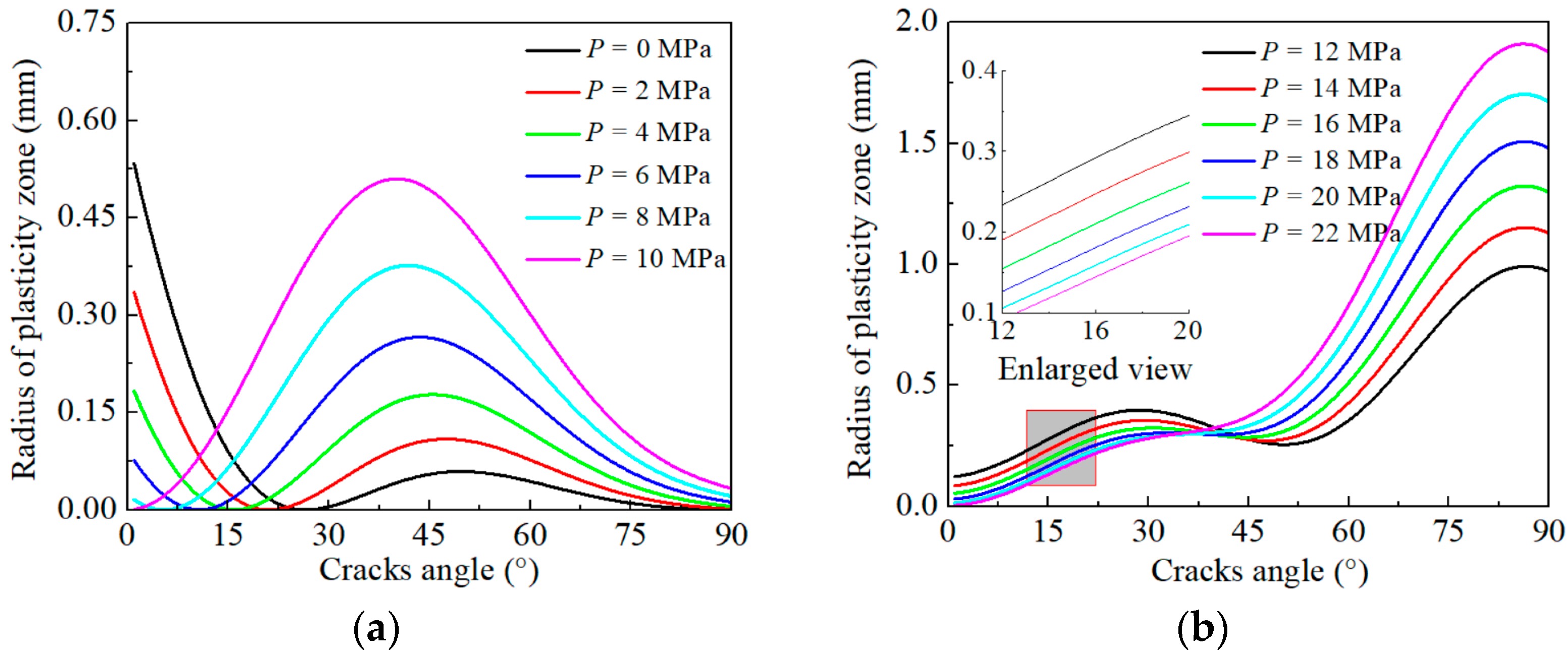
Figure 2 illustrates the distribution of r in terms of θ for a wide range of osmotic pressures. It indicates that as the osmotic pressure increases, the corresponding radius r increases, provided that the fracture dip angle remains constant. Moreover, there is a significant difference between the expansion of the fracture plastic zones under high and low osmotic pressures. Under low osmotic pressures, r first decreases, then increases, and finally decreases with the increase in the fracture dip angle. Conversely, under high osmotic pressures, the radius r rises nonlinearly as θ increases. However, a slight decrease is observed when θ varies in the range of 30–45°.
Figure 2a indicates that at low osmotic pressures and a fracture dip angle of less than 45°, the dominant fracture at the tip is of type II fractures, which occurs under shear stresses [43,44]. The difference in r values at different osmotic pressures is significant, and it exhibits a decreasing-increasing trend. Under lower osmotic pressures, r decreases more rapidly in the earlier stages, and the rate of increase in later stages is less pronounced. At a fracture dip angle of 45°, as the osmotic pressure increases gradually, r approaches an upward convex distribution. The plastic deformation caused by higher osmotic pressure is more significant and reaches the maximum r. When the fracture dip angle is smaller than 45°, the tip fracture is predominantly of type I fractures, occurring under shear stress, which reduces the plastic deformation degree of the permeable rock body. Furthermore, it is observed that as the fracture dip angle increases from 0° to 90°, the plastic zone radius decreases rapidly. The results reveal that under low permeability pressures, the friction coefficient of the fracture surface is less sensitive to the softening effect of the seepage field. This is because the permeability generates compressive stresses on the vertical fracture surface and reduces the frictional resistance produced by positive stress on the fracture surface, which limits relative sliding and increases effective shear stress on the fracture surface.
Figure 2b illustrates the three-stage variation in the radius r against the fracture dip angle under high osmotic pressure. It is observed that the radius of the plastic zone increases gradually at first, followed by a moderate decrease and a final rapid increase. The dividing points are at 45° and 60°. The late-stage expansion rate of the plastic zone is comparatively high, suggesting that the amount of expansion is proportional to osmotic pressure. The plastic deformation of rocks is significantly influenced by high and low osmotic pressures, leading to distinct differences in the formation of plastic zones. The variation in the plastic zone radius was analyzed at two pressures, P = 6 MPa and P = 18 MPa. It is found that the peak radius is 0.25 mm and 1.5 mm, respectively, indicating a six-fold difference between the two values. Additionally, the rise in the maximum radius under high osmotic pressure is greater than that under low osmotic pressure, reflecting a more significant effect of high osmotic pressure on the radius r.
The results demonstrate that the effective positive stress on the fracture surface decreases under low osmotic pressure. Consequently, the anisotropic characteristics of rock plastic deformation become increasingly complex with increasing θ. This phenomenon may originate from the competition between infiltration-induced fracture and fracture degradation. Alternatively, the fracture-inducing effect of microfractures is notably low under high osmotic pressures. The damage deformation, which is exacerbated by high osmotic pressure, induces significant plastic deformation, thereby increasing the radius of the fracture plastic zone nonlinearly and rapidly.

4.2. Effect of Poisson’s Ratio on the Plastic Zone Radius

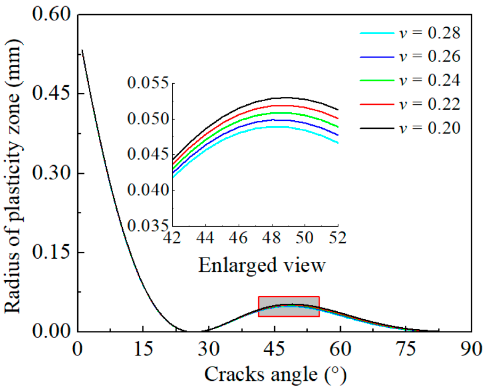
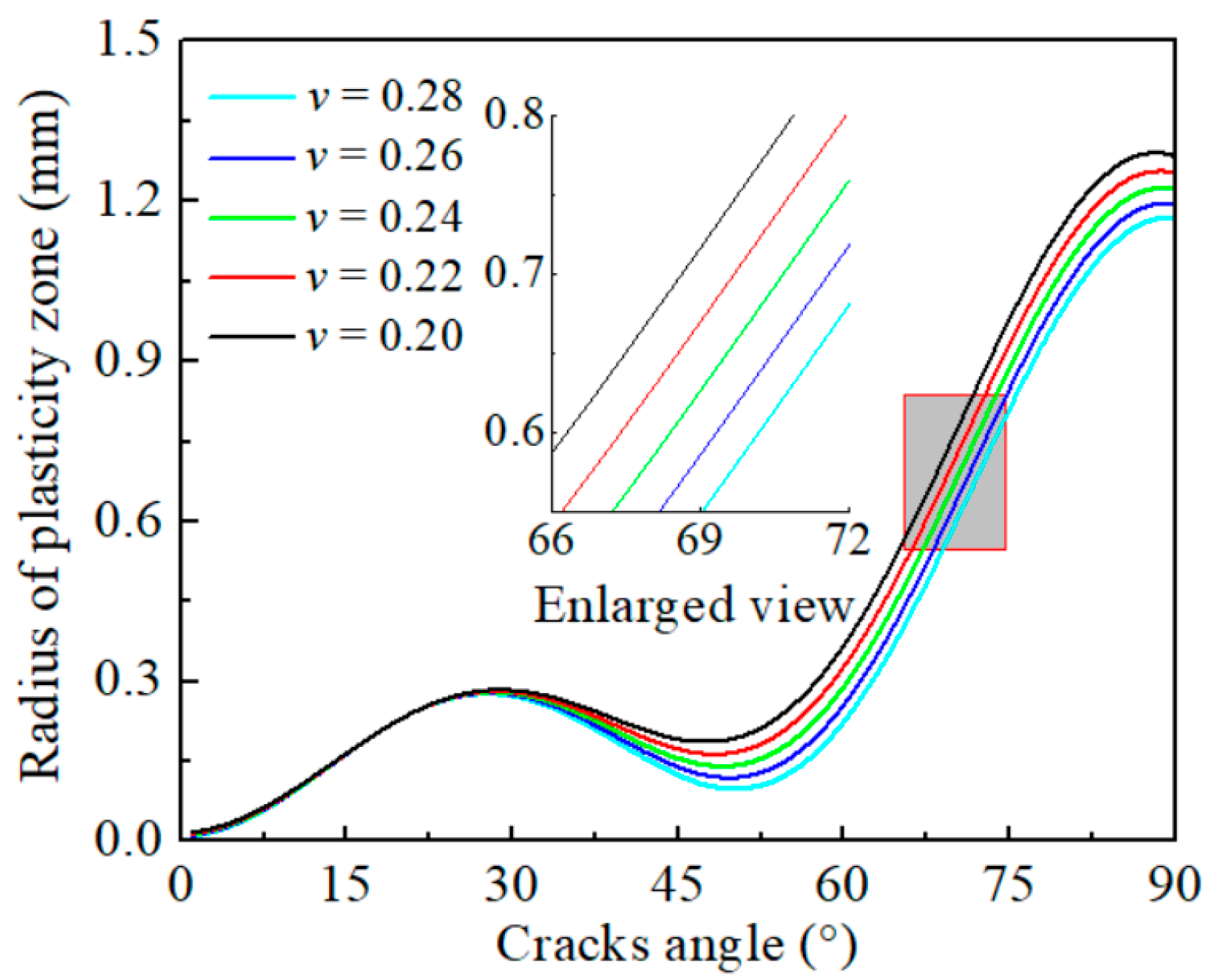
Figure 3, Figure 4 and Figure 5 illustrate the distribution of r and v for osmotic pressures 0 MPa, 6 MPa, and 18 MPa. The results indicate that for a constant fracture dip angle, r increases as v increases. The impact of Poisson’s ratio on the radius of the plastic zone varies significantly under low and high osmotic pressure. When the osmotic pressure is 0 MPa, 6 MPa, and 18 MPa, and the fracture dip angle is less than 30°, the radius r of the fractured rock remains relatively constant for different Poisson’s ratios. On the other hand, increasing Poisson’s ratio results in a considerable difference in the plastic zone radius as θ increases from 0° to 45°. In Figure 4, for instance, when Poisson’s ratio was increased from 0.20 to 0.28, the peak value of the plastic zone radius increased from 0.23 mm to 0.25 mm under a 6 MPa osmotic pressure (low osmotic pressure). Moreover, under an 18 MPa osmotic pressure (high osmotic pressure), the peak r increased from 1.17 mm to 1.29 mm, indicating a 0.12 mm increment.
The analysis indicates that the Poisson’s ratio of fractured rock has a more significant substantial impact on the plastic zone extension at the fracture tip under high osmotic pressure compared to low osmotic pressure. This is because when the fracture angle is less than 45°, the fracture tip is primarily subject to a shear type II fracture, and the variation in v has a less notable impact on the plastic zone of the fracture. Nevertheless, when the fracture angle exceeds 45°, the fracture tip experiences a shear type I fracture, and variations in Poisson’s ratio affect the rock mechanical parameters, thereby affecting the radius r of the fracture.

4.3. Effect of Fracture Length on the Plastic Zone Radius

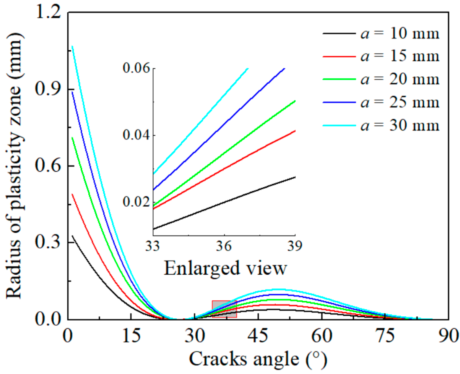
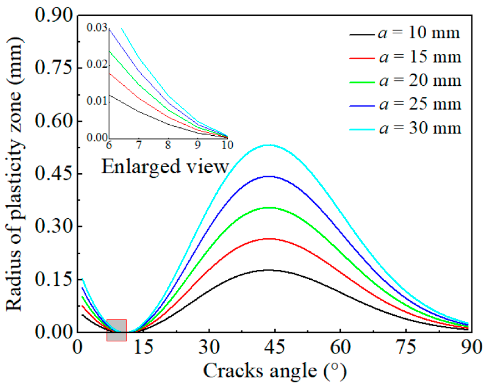
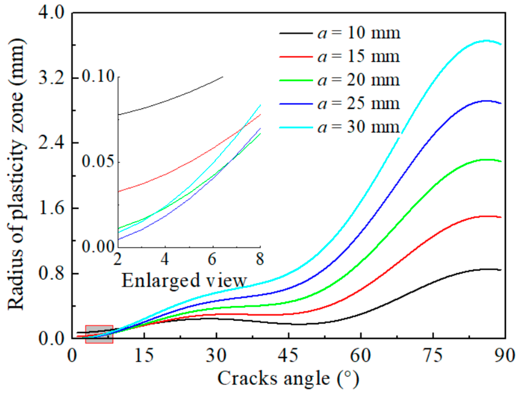
Figure 6, Figure 7 and Figure 8 illustrate the plastic zone radius versus crack inclination for different crack lengths under seepage pressures of 0 MPa, 6 MPa, and 18 MPa, respectively. The results indicate that r increases with increasing fracture length, regardless of the osmotic pressure.
The performed analysis indicates that when the osmotic pressure was 0 MPa, r did not change significantly. The evolution curve of the plastic zone radius was similar, with no apparent dispersion. As the osmotic pressure increased to 6 MPa (low osmotic pressure), the distribution of r changed significantly. The peak plastic zone radius gradually disappeared when the fracture dip angle was 0° and reappeared when θ was 45°. As the fracture length increased from 10 mm to 30 mm, the peak plastic zone radius increased from 0.18 mm to 0.45 mm. When the osmotic pressure further increased to 18 MPa, the plastic zone radius increased nonlinearly. The peak plastic zone radius occurred at a θ of 90°, and the larger the fracture length, the larger the peak plastic zone radius. As the fracture length increased from 10 mm to 30 mm, the peak plastic zone radius increased from 0.84 mm to 2.82 mm. The effect of the initial fracture length on the plastic zone radius is more obvious with the increase in osmotic pressure. The mechanical properties of the rock change with the increase in fracture length, leading to an increase in the initial damage to the rock. Moreover, osmotic pressure contributes to rock fracture tip degradation, resulting in significant plastic deformation of the fracture under stress.

5. Conclusions

This study aimed to examine the evolution of the plastic zone at the tip of I–II composite fissures under seepage conditions. An analytical solution was developed based on the Drucker–Prager yield criterion to estimate the plastic zone radius r at the fracture tip under high and low osmotic pressures. The influence of various parameters on r was analyzed. The main achievements can be summarized as follows:
(1)
The investigation of stress distribution characteristics on the fracture surface under osmotic pressure revealed that the effective positive stress features on the rock body’s fracture surface can serve as a criterion to distinguish between high and low osmotic pressures. The stress intensity factor is derived for composite fractures under osmotic pressure, taking into account the effects on rock microfractures.
(2)
An analytical expression is developed to obtain r in fractures exposed to high and low osmotic pressure. The performed analyses indicated that the value of r in fractured rocks is significantly affected by fracture parameters. When subjected to low osmotic pressure, the fracture plastic zone radius exhibited a decreasing–increasing–decreasing trend as the fracture dip angle θ increased, with the peak r occurring at 45°. The fracture length and Poisson’s ratio had no notable impact on the fracture r value.
(3)
Under high osmotic pressure, r increased with increasing θ. The effect of changes in Poisson’s ratio v on the plastic zone radius was more noticeable, with an increase in v from 0.20 to 0.28, resulting in a 10.26% rise in r. Moreover, an increase in fracture length from 10 mm to 30 mm doubled the peak plastic zone radius.
This study only focuses on the theoretical study of the evolution characteristics of the plastic deformation zone of type I–II composite fractured rock under osmotic pressure. The fracture plastic zone radius of the surrounding rock indicates that it is necessary to continue the evolution characteristics of the seepage field in fractures under the complex stress–permeability coupling environment.

Author Contributions

Conceptualization, methodology, and resources, Z.N.; methodology, data curation, and writing—original draft, Z.N., Y.C.; writing—review and editing, Y.C., T.X. and J.P. All authors have read and agreed to the published version of the manuscript.

Funding

This work was financially supported by the Innovation Capacity Support Plan of Shaanxi Province (No. 2020TD-005), 2023 High-level Talent Research Project from the Yancheng Institute of Technology (No. xjr2023019), Open Fund Project of Shaanxi Key Laboratory of Geotechnical and Underground Space Engineering (No. YT202302).

Institutional Review Board Statement

Not applicable.

Informed Consent Statement

Not applicable.

Data Availability Statement

The data used to support the findings of this study are available from the corresponding author upon request. The data are not publicly available due to privacy.

Conflicts of Interest

The authors declare no conflicts of interest.

References

  1. Feng, Z.C.; Zhao, Y.S.; Zhao, D. Investigating the scale effects in strength of fractured rock mass. Chaos Solitons Fractals 2009, 41, 2377–2386. [Google Scholar] [CrossRef]
  2. Cheng, Y.; Song, Z.P.; Xu, Z.W.; Yang, T.T.; Tian, X.X. Failure mechanism and infrared radiation characteristic of hard siltstone induced by stratification effect. J. Mt. Sci. 2024, 13, 377–396. [Google Scholar]
  3. Laghaei, M.; Baghbanan, A.; Hashemolhosseini, H.; Dehghanipoodeh, M. Numerical determination of deformability and strength of 3D fractured rock mass. Int. J. Rock Mech. Min. 2018, 110, 246–256. [Google Scholar] [CrossRef]
  4. Liu, T.Y.; Zhang, C.Y.; Cao, P.; Zhou, K. Freeze-thaw damage evolution of fractured rock mass using nuclear magnetic resonance technology. Cold Reg. Sci. Technol. 2020, 170, 102951. [Google Scholar] [CrossRef]
  5. Mao, R.; Fang, K.; Zhao, T.B.; Liu, N.W. Failure mechanism of rock with pre-existing surface crack under cone penetration test. China J. Rock Mech. Eng. 2022, 41, 1183–1192. [Google Scholar] [CrossRef]
  6. Zhao, J.S.; Duan, S.Q.; Chen, B.R. Failure mechanism of rock masses with complex geological conditions in a large underground cavern: A case study. Soil Dyn. Earthq. Eng. 2024, 177, 108439. [Google Scholar] [CrossRef]
  7. Kong, X.X.; Liu, Q.S.; Zhao, Y.F.; Pan, Y.C.; Liu, J.P. Numerical study on the influence of joint inclination on rock breaking characteristics of rock tunnel boring machine. J. Coal 2015, 40, 1257–1262. [Google Scholar] [CrossRef]
  8. Li, X.X.; Xu, Y. Hydraulic and solute transport coupling model for fractured rock mass with discrete fracture network using computational method. China J. Geotech. Eng. 2019, 41, 1164–1171. [Google Scholar] [CrossRef]
  9. Coli, N.; Pranzini, G.; Alfi, A.; Boerio, V. Evaluation of rock-mass permeability tensor and prediction of tunnel inflows by means of geostructural surveys and finite element seepage analysis. Eng. Geol. 2008, 101, 174–184. [Google Scholar] [CrossRef]
  10. Cheng, Y.; Song, Z.P.; Yang, T.T.; Han, J.J.; Wang, B.W.; Zhang, Z.K. Investigating the aging damage evolution characteristics of layered hard sandstone using digital image correlation. Constr. Build. Mater. 2022, 353, 128838. [Google Scholar] [CrossRef]
  11. Fan, Y.S.; Song, Z.P.; Xu, T.; Zhang, Y.W. Investigation of the microstructure damage and mechanical properties evolution of limestone subjected to high-pressure water. Constr. Build. Mater. 2022, 316, 125871. [Google Scholar] [CrossRef]
  12. Zhu, C.; He, M.C.; Jiang, B.; Qin, X.Z.; Qian, Y.; Zhou, Y. Numerical investigation on the fatigue failure characteristics of water-bearing sandstone under cyclic loading. J. MT Sci.-Engl. 2021, 18, 3348–3365. [Google Scholar] [CrossRef]
  13. Zhu, C.; Xu, Y.Z.; Wu, Y.X.; He, M.C.; Zhu, C.Q.; Meng, Q.X.; Lin, Y. A hybrid artificial bee colony algorithm and support vector machine for predicting blast-induced ground vibration. Earthq. Eng. Eng. Vib. 2022, 21, 861–876. [Google Scholar] [CrossRef]
  14. Zhu, C.; Karakus, M.; He, M.C.; Meng, Q.X.; Shang, J.L.; Wang, Y.; Yin, Q. Volumetric deformation and damage evolution of Tibet interbedded skarn under multistage constant-amplitude-cyclic loading. Int. J. Rock Mech. Min. 2022, 152, 105066. [Google Scholar] [CrossRef]
  15. Wu, K.; Shao, Z.S.; Jiang, Y.L.; Zhao, N.N.; Qin, S.; Chu, Z.F. Determination of stiffness of circumferential yielding lining considering the shotcrete hardening property. Rock Mech. Rock Eng. 2023, 56, 2023–2036. [Google Scholar] [CrossRef]
  16. Wu, K.; Shao, Z.S.; Sharifzadeh, M.; Hong, S.Y.; Qin, S. Analytical computation of support characteristic curve for circumferential yielding lining in tunnel design. J. Rock Mech. Geotech. Eng. 2022, 14, 144–152. [Google Scholar] [CrossRef]
  17. Liu, N.F.; Li, N.; Li, G.F.; Song, Z.P.; Wang, S.J. Method for evaluating the equivalent thermal conductivity of a freezing rock mass containing systematic fractures. Rock Mech. Rock Eng. 2022, 55, 7333–7355. [Google Scholar] [CrossRef]
  18. Tang, L.S.; Zhang, P.C.; Wang, S.J. Testing study on effects of chemical action of aqueous solution on crack propagation in rock. China J. Rock Mech. Eng. 2002, 11, 822–827. [Google Scholar]
  19. Zhao, Y.L.; Tang, J.Z.; Fu, C.C.; Wang, W.; Wang, W.J.; Luo, S.L. Rheological test and creep damage model of viscoelastic-plastic strain separation of rock. J. Rock Mech. Eng. 2016, 35, 1297–1308. [Google Scholar] [CrossRef]
  20. Zheng, S.H.; Yao, H.L.; Ge, X.R. Analysis of saturated-unsaturated seepage in fissured expansive soil. Geotech. Mech. 2007, 28, 281–285. [Google Scholar] [CrossRef]
  21. Zhao, K.; Jin, J.F.; Wang, X.J. Study on rock damage and acoustic emission based on ultrasonic velocity test of rock specimen under uniaxial compression. Rock Soil Mech. 2007, 43, 2105–2109+2114. [Google Scholar] [CrossRef]
  22. Wang, K.; Jiang, Y.F.; Xu, C. Mechanical properties and statistical damage model of coal with different moisture contents under uniaxial compression. China J. Rock Mech. Eng. 2018, 37, 1070–1079. [Google Scholar] [CrossRef]
  23. Li, H.R.; Qiao, Y.F.; Shen, R.X. Effect of water on mechanical behavior and acoustic emission response of sandstone during loading process: Phenomenon and mechanism. Eng. Geol. 2021, 294, 106386. [Google Scholar] [CrossRef]
  24. Qiu, L.W.; Zhu, L.L.; Xie, L.F. Study on strength characteristics of interlayer rocks based on thermal–mechanical coupling. Geotech. Geol. Eng. 2023, 41, 3803–3821. [Google Scholar] [CrossRef]
  25. Song, Z.P.; Wang, J.X.; Jiang, Y.N.; Liu, X.L.; Zhang, X.G. Ultrasonic tests on schist with saturated fractures under uniaxial compression. China J. Rock Mech. Eng. 2014, 33, 2377–2383. [Google Scholar] [CrossRef]
  26. Song, Z.P.; Cheng, Y.; Tian, X.X.; Wang, J.B.; Yang, T.T. Mechanical properties of limestone from Maixi tunnel under hydro-mechanical coupling. Arab. J. Geosci. 2020, 13, 402–414. [Google Scholar] [CrossRef]
  27. Song, Z.P.; Song, W.X.; Cheng, Y.; Yang, T.T.; Wang, T.; Wang, K.S. Investigation on strain characteristics and fatigue constitutive model of limestone under osmotic pressure and cyclic disturbance coupling. KSCE J. Civ. Eng. 2022, 26, 1740–1753. [Google Scholar] [CrossRef]
  28. Mu, W.; Li, L.; Liu, X.; Zhang, L.; Zhang, Z.; Huang, B.; Chen, Y. Diffusion-hydraulic properties of grouting geological rough fractures with power-law slurry. Geomech. Eng. 2020, 21, 357–369. [Google Scholar] [CrossRef]
  29. Wang, H.; Dong, Q.; De La Vaissière, R.; Vu, M.; La Borderie, C.; Gallipoli, D.; Sun, H. Investigation of hydro-mechanical behaviour of excavation induced damage zone of callovo-oxfordian Claystone: Numerical Modeling and In-situ Experiment. Rock Mech. Rock Eng. 2022, 55, 6079. [Google Scholar] [CrossRef]
  30. Zhao, H.; Geng, Q.; Liu, X. Influence of freeze–thaw cycles on mechanical properties of pervious concrete: From experimental studies to discrete element simulations. Constr. Build. Mater. 2023, 409, 133988. [Google Scholar] [CrossRef]
  31. Deng, P.H.; Liu, Q.S.; Huang, X.; Pan, Y.C.; Wu, J. FDEM numerical modeling of failure mechanisms of anisotropic rock masses around deep tunnels. Comput. Geotech. 2022, 142, 104535. [Google Scholar] [CrossRef]
  32. Lisjak, A.; Garitte, B.; Grasselli, G.; Müller, H.R.; Vietor, T. The excavation of a circular tunnel in a bedded argillaceous rock (Opalinus Clay): Short-term rock mass response and FDEM numerical analysis. Tunn. Undergr. Space Technol. 2015, 45, 227–248. [Google Scholar] [CrossRef]
  33. Sherzer, G.L.; Alghalandis, Y.F.; Peterson, K.; Shah, S. Comparative study of scale effect in concrete fracturing via lattice discrete particle and finite discrete element models. Eng. Fail. Anal. 2022, 135, 106062. [Google Scholar] [CrossRef]
  34. Haile, B.F.; Sherzer, G.L.; Peterson, K.; Grasselli, G. Progressive highly stressed volume for size effect analysis. Constr. Build. Mater. 2023, 400, 132600. [Google Scholar] [CrossRef]
  35. Cheng, Y.; Song, Z.P.; Wu, F.H.; Zhu, X.P.; Yuan, W. Investigating the mechanical deterioration effect of hard sandstone induced by layer structure under uniaxial compression. Buildings 2024, 14, 51. [Google Scholar] [CrossRef]
  36. Li, D.X.; Wang, E.Y.; Feng, X.J.; Wang, D.M.; Zhang, X.; Ju, Y.Q. Weak current induced by coal deformation and fracture and its response to mine seismicity in a deep underground coal mine. Eng. Geol. 2023, 315, 107018. [Google Scholar] [CrossRef]
  37. Si, X.F.; Luo, Y.; Luo, S. Influence of lithology and bedding orientation on failure behavior of “D” shaped tunnel. Theor. Appl. Fract. Mech. 2024, 129, 104219. [Google Scholar] [CrossRef]
  38. Song, Z.P.; Cheng, Y.; Zhang, Z.K. Tunnelling performance prediction of cantilever boring machine in sedimentary hard-rock tunnel using deep belief network. J. Mt. Sci. 2023, 20, 2029–2040. [Google Scholar] [CrossRef]
  39. Wu, K.; Song, J.A.; Zhao, N.N.; Shao, Z.S. Study on the time—Dependent interaction between surrounding rock and yielding supports in deep soft rock tunnels. Int. J. Numer. Anal. Met. 2023, 47, 3650. [Google Scholar] [CrossRef]
  40. Wu, K.; Zheng, X.M.; Zhao, N.N. Effect of compressible layer on time-dependent behaviour of soft-rock large deformation tunnels revealed by mathematical analytical method. Appl. Math. Model 2024, 126, 457–481. [Google Scholar] [CrossRef]
  41. Li, Y.; Yi, Z.J.; Wang, M.; Su, K. The stress intensity factor of a finite-width plate with a mode-ⅰ center crack subjected to uniform stress on the crack surface near the crack tip. Appl. Math. Mech. 2020, 41, 1083–1091. [Google Scholar] [CrossRef]
  42. Zhao, Y.L.; Wan, W.; Wang, W.J.; Wang, M.; Peng, Q.Y. Fracture experiments on ordered multi-crack body in rock-like materials under uniaxial compression and numerical simulation of wing cracks. China J. Geotech. Eng. 2013, 35, 2097–2109. (In Chinese) [Google Scholar]
  43. Lee, H.; Jeon, S. An experimental and numerical study of fracture coalescence in pre-cracked specimens under uniaxial compression. Int. J. Solids Struct. 2010, 48, 979–999. [Google Scholar] [CrossRef]
  44. Pu, C.Z.; Cao, P.; Zhang, C.Y.; Fu, Z.Z. Fracture failure mechanism of rock with closed crack and judging criterion of seepage pressure under biaxial compression. Rock Soil Mech. 2015, 29, 470–474. [Google Scholar] [CrossRef]
  45. Zeng, J.J.; Zhang, Z.J.; Zhang, B.B.; Pu, C.C. Fracture test and analysis of horizontal fissure rock-like specimens influenced by apertures. China J. Geotech. Eng. 2020, 42, 523–532. [Google Scholar] [CrossRef]
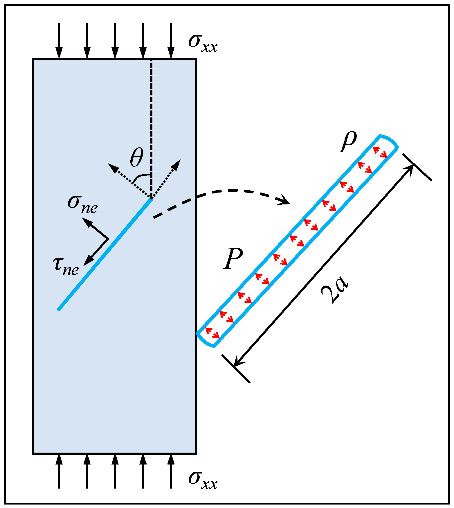
Figure 1. Model of rock mass fracture under uniaxial compression load.
Applsci 14 01796 g001
Figure 2. The distribution of r under different osmotic pressures. (a) Low osmotic pressure; (b) high osmotic pressure.
Applsci 14 01796 g002
Figure 3. The distribution of r and θ for various v (P = 0 MPa).
Applsci 14 01796 g003
Figure 4. The distribution of r and θ for different v (P = 6 MPa).
Applsci 14 01796 g004
Figure 5. The distribution of r and θ for different v (P = 18 MPa).
Applsci 14 01796 g005
Figure 6. The distribution of r and θ at different fracture lengths (P = 0 MPa).
Applsci 14 01796 g006
Figure 7. The distribution of r and θ at different fracture lengths (P = 6 MPa).
Applsci 14 01796 g007
Figure 8. The distribution of r and θ at different fracture lengths (P = 18 MPa).
Applsci 14 01796 g008
Disclaimer/Publisher’s Note: The statements, opinions and data contained in all publications are solely those of the individual author(s) and contributor(s) and not of MDPI and/or the editor(s). MDPI and/or the editor(s) disclaim responsibility for any injury to people or property resulting from any ideas, methods, instructions or products referred to in the content.