Abstract
This study explores the efficacy of a sacrificial anode cathodic protection (SACP) system with an activated carbon-based conductive mortar in bridge structures. In the previous Part 1 study, various admixtures were compared to identify a conductive mortar for enhancing the performance of the SACP system, assessed through electrical conductivity, resistivity, cathodic protection (CP) potential and current, and 4 h depolarization potential. Part 2 extends the investigation by applying the developed conductive mortar containing activated carbon to an SACP system on an actual bridge structure in which corrosion has already been initiated. Before CP installation, the physical properties of the conductive mortar were evaluated to satisfy the standard requirements for concrete structure maintenance. Subsequently, zinc mesh and bulk anodes were installed on the bridge pier, followed by the application of a conductive mortar with an admixture ratio of 5%. Over a four-year period, performance was measured through regular 4 h depolarization potential checks and visual inspections. The SACP system with the conductive mortar demonstrated superior CP performance compared to the general mortar, confirming the effectiveness of the developed conductive mortar. Visual inspection after four years confirmed the workability of the SACP system with conductive mortar.
1. Introduction
Steel corrosion in concrete has been identified as a primary cause of damage and deterioration in reinforced concrete structures globally, primarily due to the presence of chlorides [1,2,3,4,5,6,7]. This is normally difficult to achieve because a strong passive film is formed on the steel surface in an alkaline environment inside the concrete. However, it begins to deteriorate owing to chloride intrusion, which decreases the pH and destroys the passive film. Marine tidal and splash zones are especially susceptible to corrosion because of their relatively rich oxygen, water, and chloride contents, as well as frequent wet–dry cycles [8,9,10]. It is well known that corrosion treatment is expensive, accounting for about 3–4% of the gross domestic product of each nation [11]. For example, USD 2.5 trillion, or 3.4% of the world’s gross domestic product, was spent in 2013 on solving the worldwide corrosion issue [12].
Cathodic protection (CP) is regarded as a dependable and efficient method for protecting against corrosion in reinforced concrete structures that have been harmed by chloride penetration [13,14]. CP can be divided into impressed current CP (ICCP) and sacrificial anode CP (SACP). SACP uses the potential difference between the anode and cathode. In other words, the CP current flows from the anode to the cathode because the anode (e.g., zinc or aluminum) has a lower potential than the cathode [15,16], which protects the cathode cathodically. Although SACP can offer simpler and less expensive corrosion protection, its implementation in a high-resistance environment is challenging owing to its low current intensity, which significantly reduces the effectiveness of CP and the resulting issues of throwing power [17,18]. Because the throwing power is only a few centimeters, depending on the surrounding conditions, the workability of the SACP system in marine tidal and splash zones is limited [19,20,21]. To address the inherent limitations of SACP, a hybrid CP system that integrates ICCP and SACP was developed [22,23]; however, this approach introduces challenges to practicality, as it increases the system complexity and may lead to interference between the two CP systems.
Researchers have developed a versatile conductive mortar, supported by widespread supports, to enhance a range of properties, including electrical and mechanical characteristics, wear resistance, oxidation resistance, and volume and contact resistivity. This innovative mortar has applications in diverse areas, such as extending the fatigue life, de-icing, and self-monitoring materials [24,25]. Notably, extensive exploration and experimental evaluation have been conducted on carbon fiber conductive mortars for CP systems. For example, Fu and Chung [25] assessed the volume and contact resistivity of conductive mortar, which play a pivotal role in the design of the anode for a CP system. Hou and Chung [26] conceptualized conductive mortar as the primary anode for ICCP systems, affirming its effectiveness through experiments conducted in arid environments. Bertolini et al. [27] integrated a primary anode with a conductive mortar anode composed of Ni-coated carbon fibers. They rigorously examined the performance of an ICCP system using the proposed anode system on concrete specimens with and without chloride contamination, accounting for both dry and wet conditions. Xu and Yao [28] explored a comparable ICCP system employing a conductive mortar in conjunction with a primary anode, with a specific emphasis on the current distribution by the conductive mortar anode concerning the initial corrosion state, concrete resistivity, and current density magnitude. Expanding their research, Xu and Yao [29] further scrutinized the mechanical, electrical, and electrochemical properties of conductive mortar. Carmona et al. [30] conducted a comparative analysis of the effectiveness of CP, cathodic prevention, and electrochemical chloride extraction. They used a graphite–cement paste layer as the anode for a conductive mortar coupled with a primary graphite anode. They assessed the proposed systems using specimens immersed in chloride. There were also previous investigations on the effect of the surrounding environment and the sustainability of conductive mortar (e.g., [31,32]).
In this study, a novel conductive mortar was investigated to enhance the effectiveness of CP by reducing its resistivity. In contrast to previous investigations that primarily emphasized electrical conductivity to support the primary anode of the ICCP system, this study placed greater emphasis on the role of conductive mortar in facilitating ionic movement from the anode to the rebar in the SACP system. Specifically, the objective was to decrease concrete resistivity and sustain its humidity over an extended period. The integration of the proposed conductive mortar can significantly enhance the applicability of SACP in tidal and splash zones. In Part 1 [33], a variety of potential conductive mortars, such as activated carbon, bentonite, zeolite, and geopolymers, were compared through laboratory experiments. Additionally, chemical agents were added to the admixtures to further enhance conductivity. The chemical agents selected were sodium hydroxide, calcium hydroxide, lithium hydroxide, and sodium chloride. The findings indicate that the conductive mortar based on activated carbon exhibits superior effectiveness in terms of resistivity, CP potential and current, and depolarization potential. In Part 2 of this paper, the SACP performance using a conductive mortar containing activated carbon was tested over four years in an actual bridge structure in South Korea. The bridge experiences tidal variations twice per day and is thus regarded as a corrosion-accelerating region. The performance of the proposed conductive mortar and SACP system was evaluated through basic physical tests before CP application, visual inspection after four years, and depolarization measurements for four years. Given that previous studies have not investigated similar applications of conductive mortars in SACP systems or their field applications, the findings of this study can provide valuable insights for engineers and researchers in related fields.
2. Bridge Structure
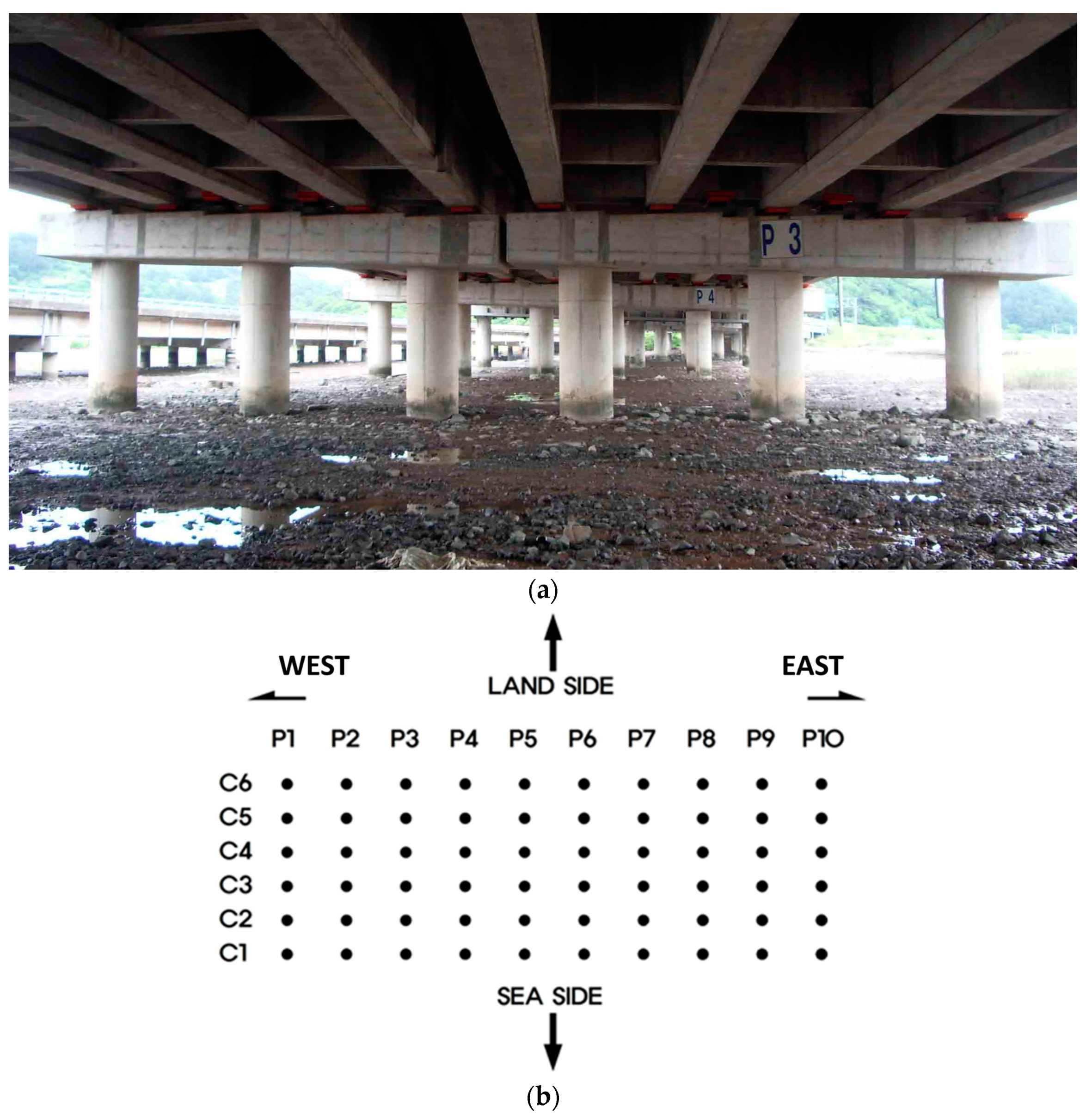
This study investigates the implementation of the SACP system on a concrete structure, specifically a coastal bridge in South Korea, as shown in Figure 1. The bridge, stretching 331.24 m and featuring 60 piers across 10 spans, was completed in 1992 and has been in operation for approximately 30 years. The bridge spans from east to west. Piers with a 1.2 m diameter and heights varying from 1 to 6 m above the ground experience a tidal variation of approximately 2 m. Daily exposure to water and drying cycles during ebb tides creates a corrosive environment. Initially, the SACP system was applied to all 60 piers, and the performance was poor in many of the piers within a short period of time owing to the low humidity and water level. Thus, the SACP system with activated carbon was applied to seven piers later to evaluate its effectiveness in performance enhancement.

Figure 1.
Entire view of the bridge before the CP application (a) and top view with column numbers (b).
3. Corrosion Evaluation
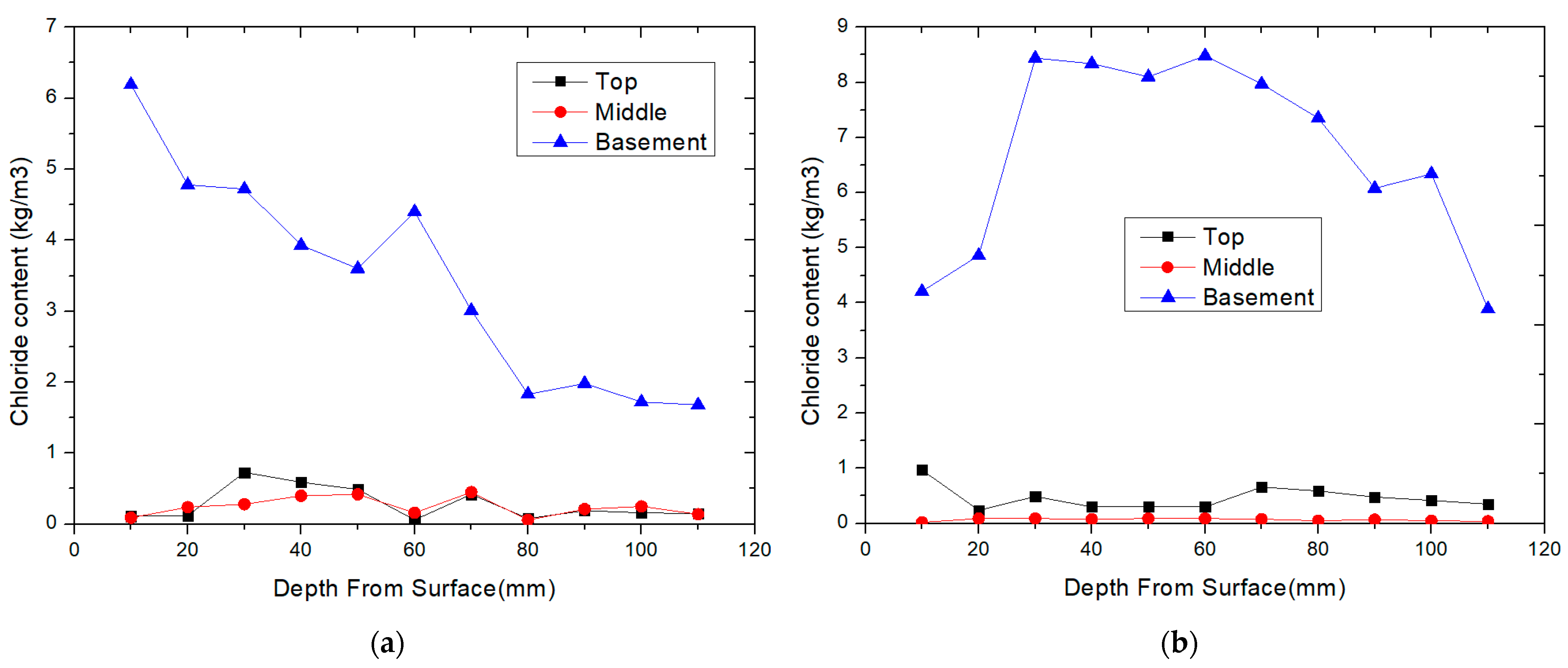
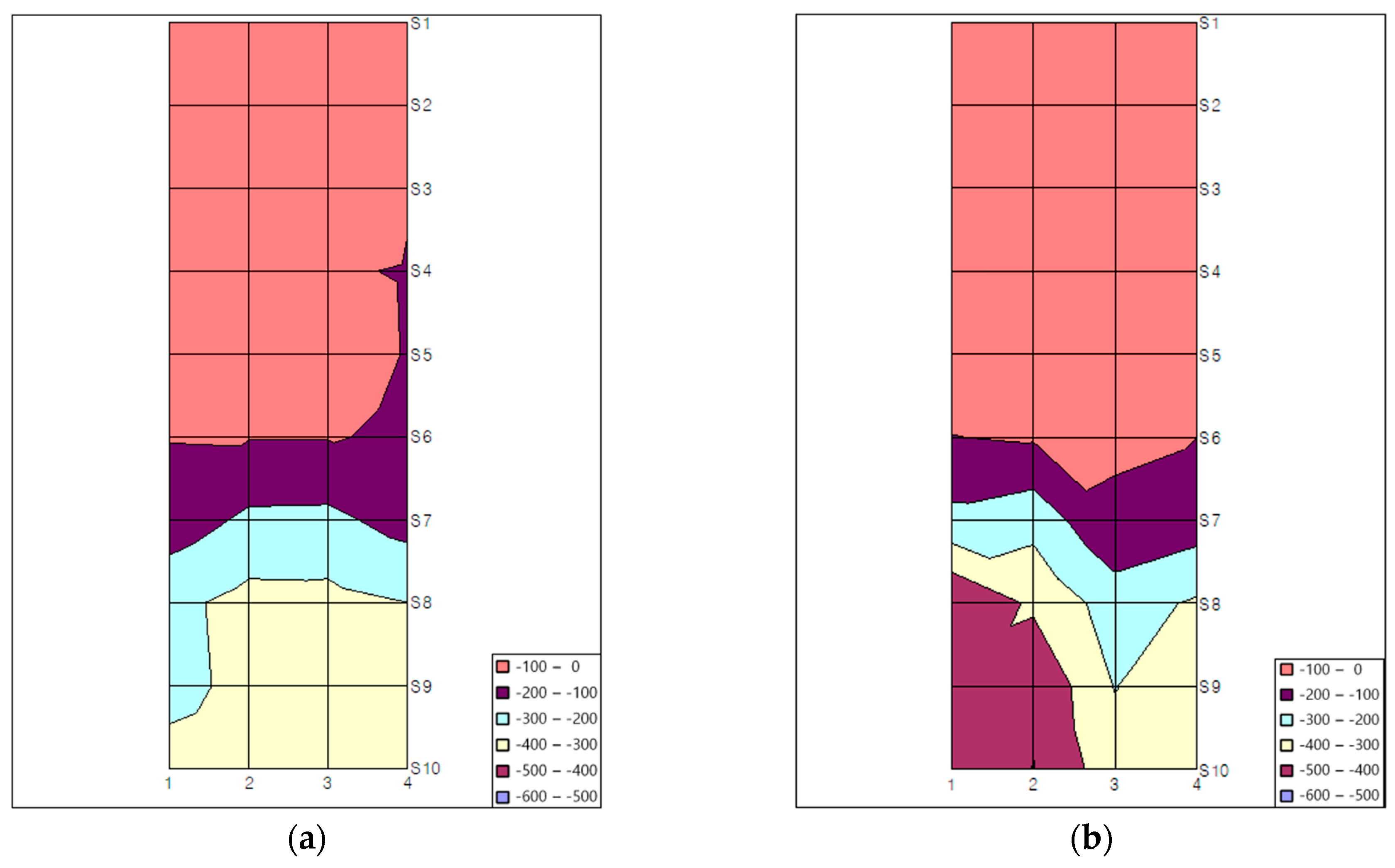
Before applying the CP system, a visual inspection was performed to evaluate the severity of corrosion. As shown in Figure 2, the bridge columns exhibited numerous corrosion-induced cracks, which caused concrete deterioration and localized damage to the reinforcing bars. In addition, after obtaining specimens from the piers at various locations, the chloride content as a function of depth was evaluated in the laboratory, as shown in Figure 3. The chloride content was measured at different heights: basement (approximately 0 m), middle (approximately 1.5 m), and top (approximately 3 m). The basement part was mostly submerged in saline water; the middle part was submerged 1–2 times during the month; the top part was not submerged, and the presence of chloride was mostly due to water splashes. The surface chloride content was high in the basement but decreased significantly at higher heights. In addition, the deeper the location, the lower the chloride content tended to be. These findings make sense because the chloride content is mostly due to splashes in the middle and top sections, and chloride penetration starts from the outer shell. Notably, the chloride content near the rebar location exceeds the critical threshold of 6.34 kg/m3 for many columns, based on an internal report, which indirectly indicates that corrosion has already been initiated. Figure 4 shows the corrosion potential as a function of pier location. In general, the lower the potential, the greater the possibility of rebar corrosion. The lower sections have a very low potential of less than −350 mV/CSE, indicating that severe corrosion is expected in those sections. The top section maintains the novel condition with a potential higher than −100 mV/CSE, which means that the possibility of corrosion in that section is low due to less invasion of chloride. Visual inspection and chloride content/potential measurements indicated that the corrosion deterioration was in the acceleration phase, which is the rationale for the need for CP system application.
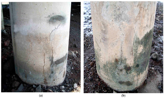
Figure 2.
Examples of damaged/cracked piers caused by chloride. (a) P2C4 (west direction); (b) P5C1 (east direction).
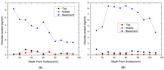
Figure 3.
Chloride content as a function of the depth from surface and measurement locations (on the x-axis, 0 mm denotes the location of the surface, while 120 mm denotes a radial distance of 120 mm from the surface). (a) P2C4 (west direction); (b) P5C1 (east direction).
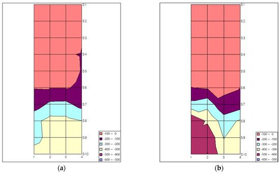
Figure 4.
Corrosion potential distribution. (a) P2C4 (west direction); (b) P5C1 (east direction).
4. Methods
4.1. Conductive Mortar Material
Although there are no international guidelines for the conductive mortar used in CP, it is generally expected to have a lower resistivity than regular concrete or mortar to ensure optimal performance for the SACP system. In addition, despite its low resistivity and excellent performance, the usability of mortar becomes challenging if its properties are substantially compromised by unsatisfactory compressive strength and durability. Conductive mortar must demonstrate strength and characteristics comparable to those of commonly used mortars to be practically applied to concrete structures.
Activated carbon-based conductive mortar was also considered, as shown in Table 1. As mentioned before, in Part 1 [33], a variety of potentially conductive mortars, such as activated carbon, bentonite, zeolite, and geopolymers, were compared through laboratory experiments. Additionally, chemical agents have been used to further enhance the conductivity. In a previous study, activated carbon-based conductive mortar was found to be the most effective based on measurements of resistivity, CP current and potential, and depolarization potential. In particular, the activated carbon in the present study, obtained from coconut-shell char, displayed excellent adsorption and removal capabilities owing to its high hardness and surface area. The activated carbon, in powder form with a particle size of 12 mesh (1.70 mm) × 30 mesh (0.60 mm), had an adsorption capacity of 900 mg/g or more, moisture content of 5% or less, hardness of 95% or more, grading of the aggregate of 90% or more, an average pore diameter of 14–18 Å, and a pH of approximately 9–11. More importantly, it has a surface area of approximately 1000 m2/g.

Table 1.
Mix design for mortar at different substitution ratios (in the table, the admixture ratio is defined as the volume of admixture divided by the volume of admixture and sand).
4.2. Basic Property Tests of Conductive Mortar
This study begins with basic property tests of the suggested conductive mortar at different substitution ratios. Basic property tests measured the flexural strength, compression strength, bonding strength under standard and thermal cycling conditions, permeability, water absorption coefficient, moisture permeation resistance, and length variation ratio. The selected test criteria were based on the standards for testing polymer cement mortar for concrete structure repair, outlined in KS F 4042 [34]. Note that before the tests and application of the developed conductive mortar, workability was tested through flow tests. Similar measures are slump tests for concrete [35].
4.3. Installation of SACP System to the Bridge Pier
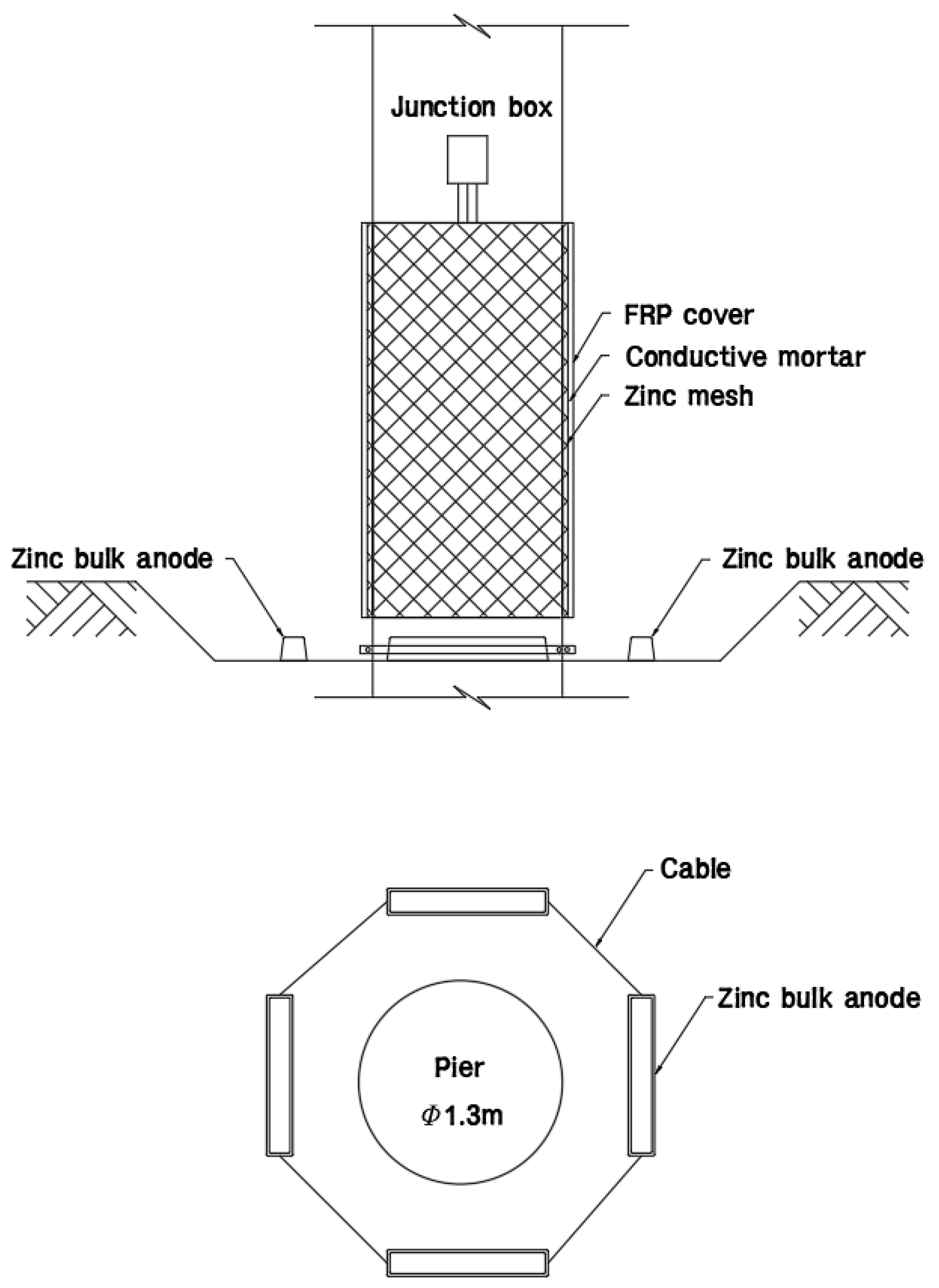
Figure 5 and Figure 6 show the SACP installation drawing and installation process, respectively. SACP using conductive mortar was implemented for seven piers among the 60 piers. The sides of the columns were washed with high-pressure water to remove impurities. Subsequently, two types of anodes were installed on the bridge pier, as shown in Figure 5. The zinc mesh was affixed to the sidewalls of the structure, and the four zinc bulk anodes were positioned on the topsoil of the expanded foundation beneath the pier. Based on the National Association of Corrosion Engineers (NACE) CP Standard [36], the lifetime of the zinc mesh anode was expected to be 37.2 years with an anode weight of 88.27 kg, utilization factor of 85%, zinc mesh efficiency of 90%, and consumption rate of zinc of 10.7 kg/A-year. Next, the installation of the Zn bulk anodes involved an excavation of approximately 0.5 m, securing the installation location beforehand, and leveling the ground. After placing the four Zn bulk anodes in the north, south, east, and west directions, they were electrically linked using cables. The Zn bulk anode had dimensions of 161 mm × 80 mm × 570 mm and a weight of 25.2 kg. It has a current efficiency of 95% or higher and a consumption rate of 11.23 kg/A-year or less. Subsequently, a conductive mortar was placed. After the conductive mortar was cured, an FRP cover was installed to prevent a decrease in current flow and efficiency reduction owing to the increased resistivity of the mortar caused by moisture evaporation from the surface. The FRP cover was made of a high-strength glass fiber composite material and was installed not only to enhance the performance of the method but also for aesthetic considerations. To operate the SACP system, the wires connected to the anodes on the column sidewalls were connected to a junction box. The terminal box was installed on the sidewalls of the columns, and the wires connected to the zinc mesh, bulk zinc, and reinforcing bars were connected to the junction box. It was designed and installed to allow on–off control of the CP system using a switch to measure the 4 h depolarization potential. Note that various standards such as ASTM and ACI standards can be employed for the CP system design and measurement for concrete or mortar specimens [37,38,39].
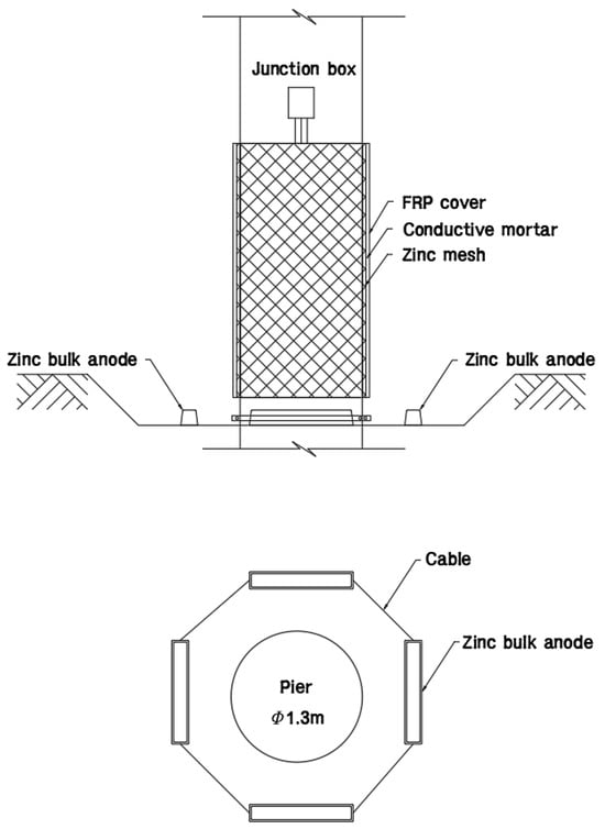
Figure 5.
SACP installation drawing.
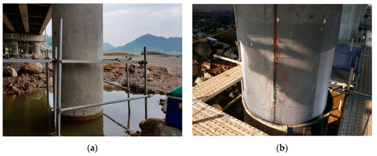

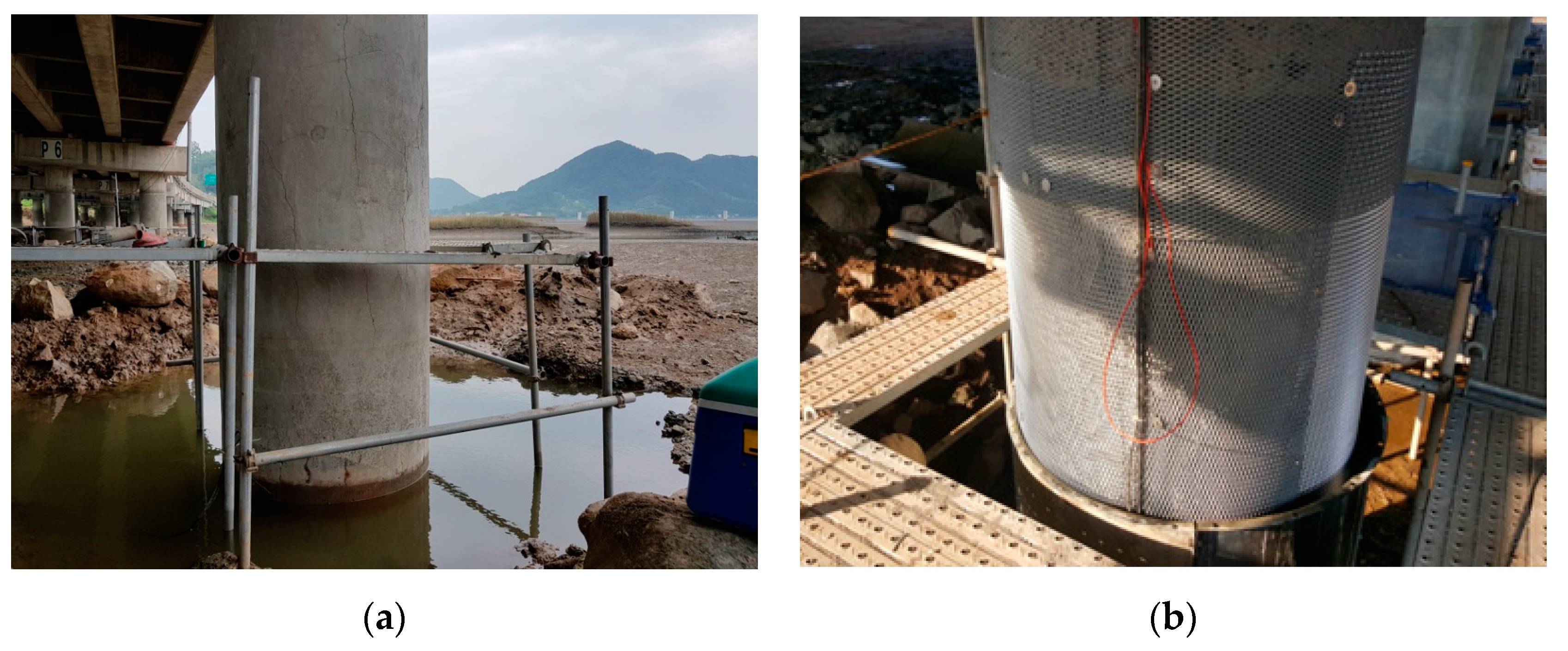
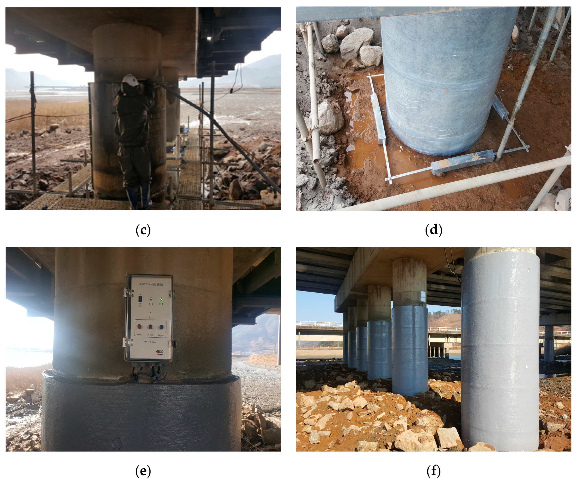
Figure 6.
Entire view of the bridge before the CP application. (a) Grinding; (b) Zinc mesh installation; (c) Conductive mortar grouting; (d) Zinc bulk anode installation and FPR cover attachment; (e) Junction box installation; (f) Paint application.
ICCP performance was evaluated using the NACE standard with a depolarization potential of 100 mV [36]. This approach involves inducing depolarization of the potential of the reinforcing steel to over 100 mV. The electrical linkage between the Zn anode and the reinforcing steel was severed, and the potential was promptly gauged. After a 4 h interval with an interrupted electrical connection, the depolarization potential was measured. A disparity exceeding 100 mV between the final recorded potential and the initial potential signifies appropriate implementation of the CP system. Notably, the depolarization potential should exceed 100 mV, excluding changes attributable to the IR drop.
5. Results and Discussions
5.1. Basic Property Test
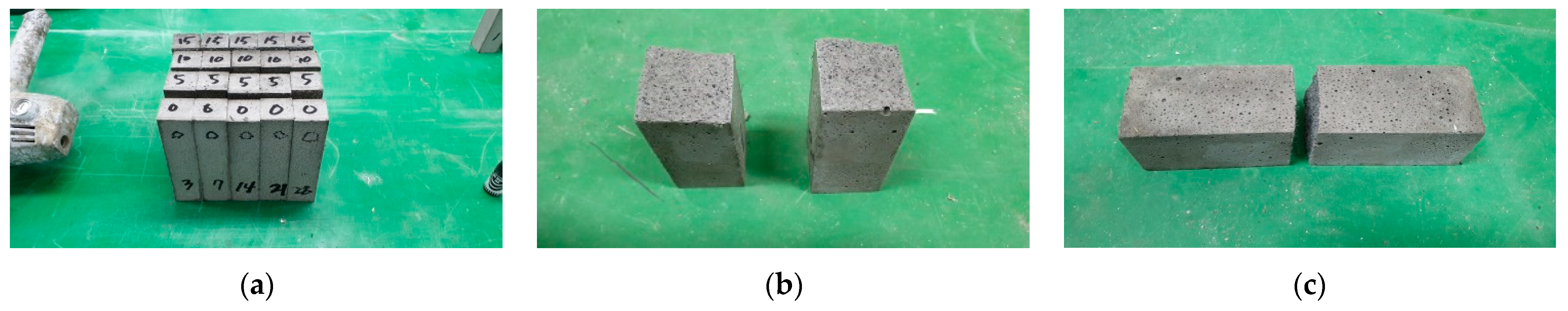
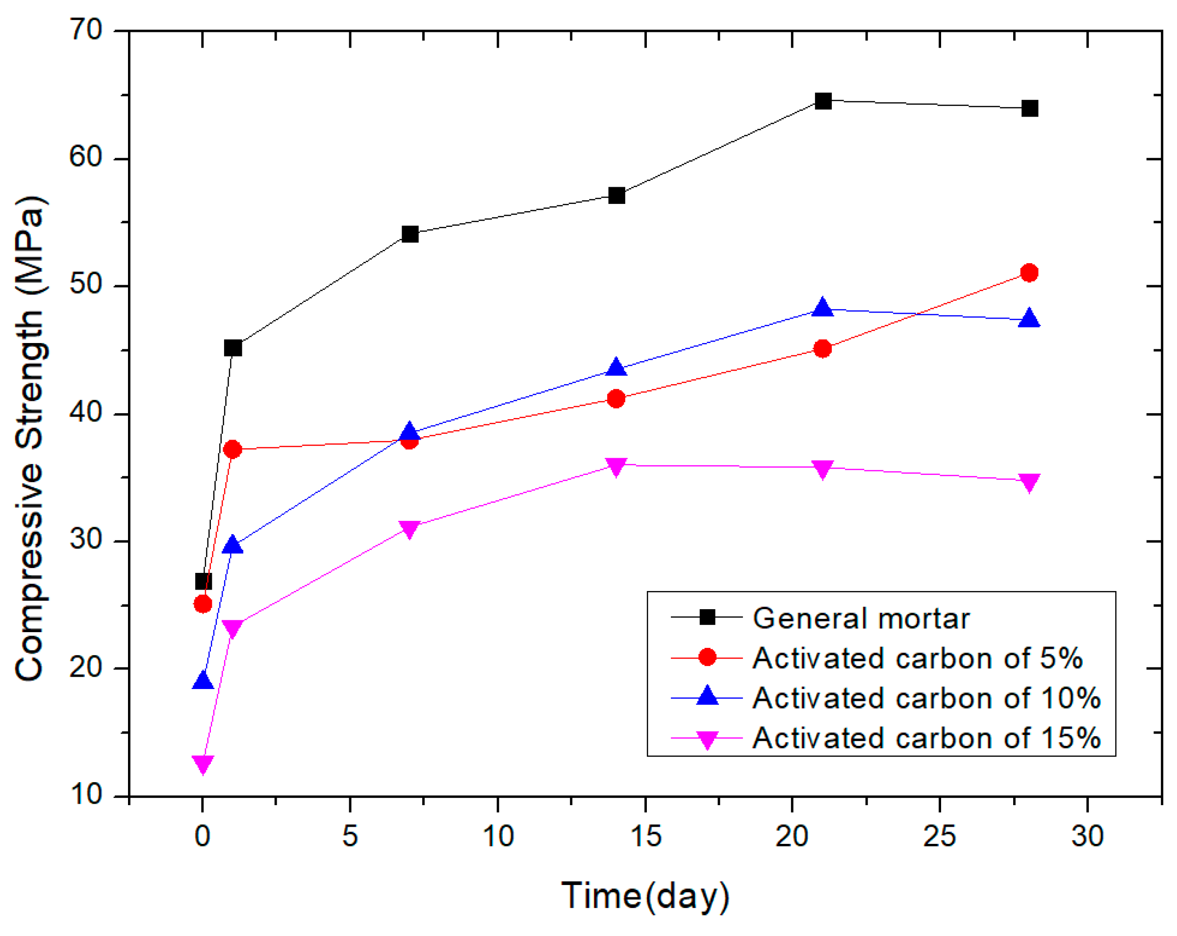
Figure 7 shows the specimens before and after the compressive and flexural strength tests. Figure 8 shows the compressive strengths of the specimens with different amounts of activated carbon with admixture ratios of 5%, 10%, and 15%. The compressive strength test was conducted on days 1, 3, 7, 14, 21, and 28 after the specimen was produced, following the KS F 4042 test method. Owing to its fast-hardening nature, a relatively high initial strength was measured for all the specimens. The 28-day strength of general mortar was 63.9 MPa, while conductive mortar showed reduced strengths of 51 MPa (5%), 48.8 MPa (10%), and 34.7 MPa (15%) depending on the amount of conductive material. The strength varied depending on the curing time and the amount of conductive material. The strength of activated carbon was lower than that of sand #6, and it was determined that the strength decreased with increasing amounts of activated carbon. However, it is judged that even with more than 15% activated carbon, the compressive strength of the mortar will be sufficiently manifested because all the measured mortars satisfied the test criterion of 20 MPa for testing polymer cement mortar for concrete structure repair outlined in KS F 4042 [34].
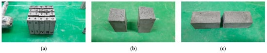
Figure 7.
Prepared specimen (a), specimen after compressive strength test (b), and specimen after flexural strength test (c).
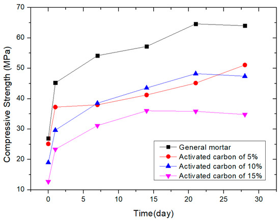
Figure 8.
Compressive strength of mortar with different amounts of activated carbon.
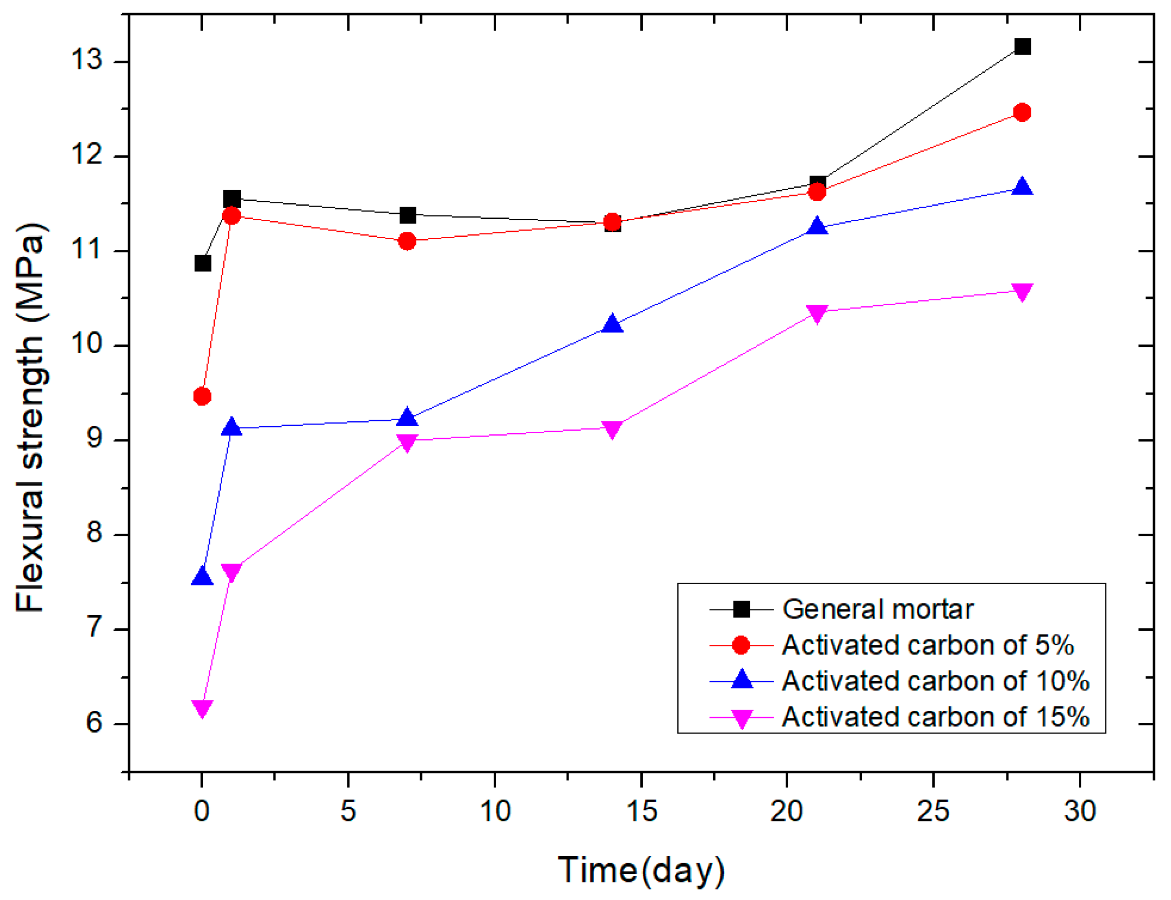
Figure 9 shows the flexural strengths of the specimens with different amounts of activated carbon. Flexural strength was measured in the same manner as compressive strength. The flexural strength was approximately 1/5–1/7 of the compressive strength. As shown in Figure 9, the 28-day strength of general mortar was 13.1 MPa, and conductive mortar showed reduced strengths of 12.4 MPa (5%), 11.6 MPa (10%), and 10.5 MPa (15%) depending on the amount of activated carbon. Nevertheless, all the measured mortars satisfied the test criterion of 6 MPa for testing polymer cement mortar for concrete structure repair outlined in KS F 4042 [34]. Compared to the compressive strength, there was no significant difference in the flexural strength between the general mortar and conductive mortars. Because the flexural strength is governed by the attachment of aggregates and mortar, the addition of activated carbon has a minimal impact on the flexural strength. However, a reduction in flexural strength was evident depending on the amount of activated carbon. Similar to the compressive strength, the lower strength of activated carbon compared to grade sand #6 is considered to be the cause of the strength reduction. Nevertheless, even with more than 15% activated carbon, the flexural strength of the mortar was sufficiently manifested.
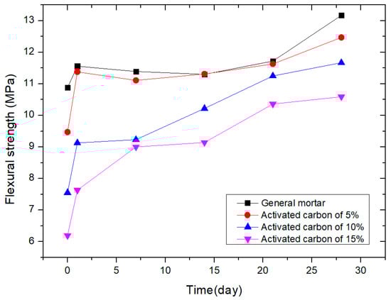
Figure 9.
Flexural strength of mortar with different amounts of activated carbon.
Next, as presented in Table 2, with the new testing specimens, the bonding strength, permeability quantity, water absorption coefficient, moisture permeation resistance, and length variation ratio were measured according to KS F 4042 using only the 5% activated carbon specimen. The 5% activated carbon was finally selected for application to the bridge structure to evaluate the initial feasibility. Note that the results in Table 2 are different from those in Figure 8 and Figure 9 because the measurement in Table 2 was much later than 28 days for the newly made specimens. The flexural strength was 6.5 MPa, and the compressive strength was 42.1 MPa. Although the strength decreased due to the inclusion of activated carbon, the basic properties were satisfactory. The most important indicator of repair mortar is the bond strength, and the results under standard conditions and after thermal cycling both exceeded 1 MPa, demonstrating excellent bond strength. The permeability, water absorption coefficient, and moisture penetration resistance were below the allowed limits, while the resistivity was reduced. Typically, mortar exhibits drying shrinkage after curing; however, the measurement of the length variation ratio shows almost no change, indicating the absence of drying shrinkage, measured at approximately 50% of the standard. All the test items sufficiently satisfied the performance criteria, and it was determined that even with the addition of activated carbon, the performance of the mortar could be maintained while improving efficiency.
Table 2.
Property of conductive mortar including 5% activated carbon.
5.2. Depolarization Potential Measurement
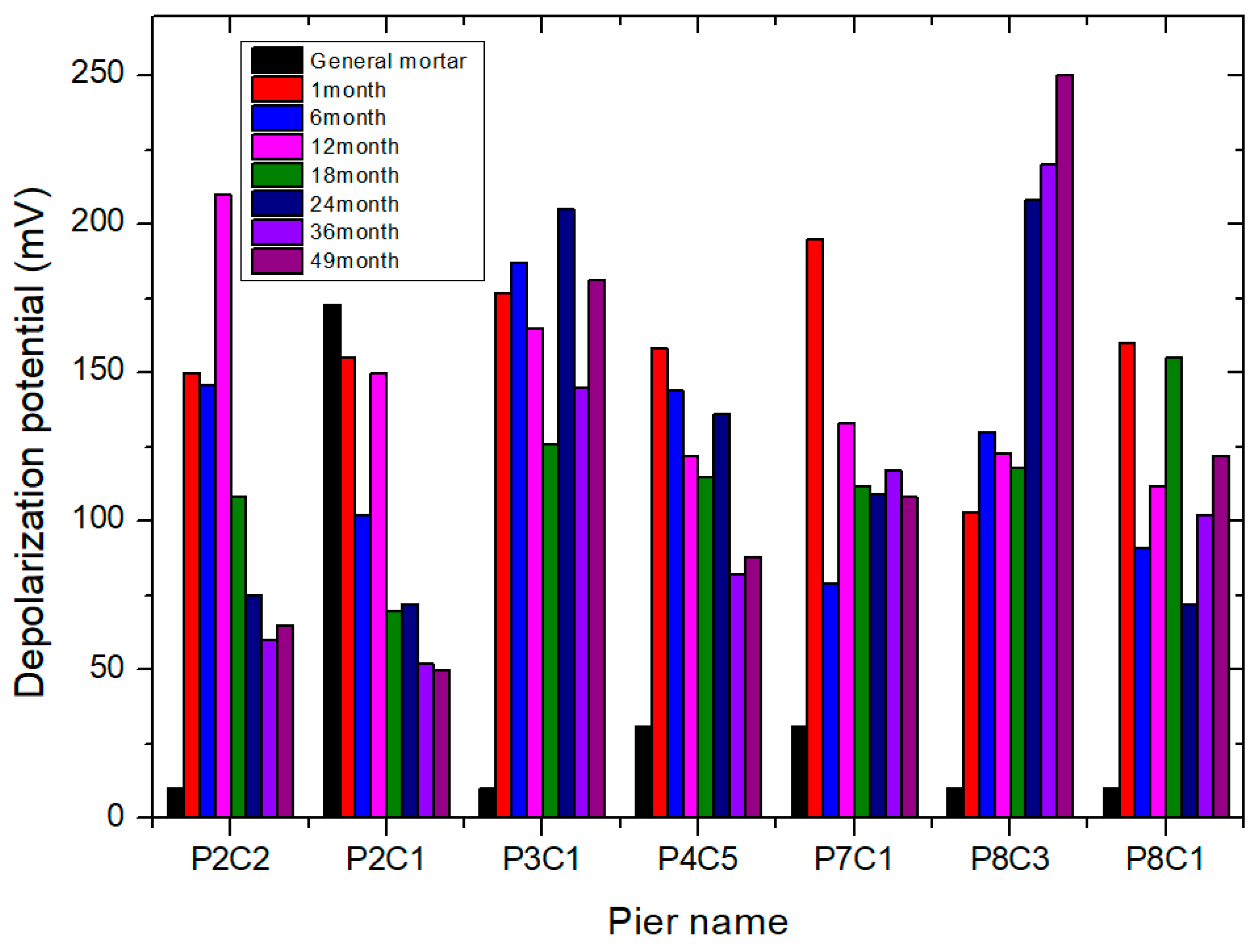
Next, the depolarization potential was measured over 4 years. As mentioned previously, seven columns of the reinforced concrete bridge structure were equipped with an SACP system with conductive mortar over four years, and the measurements were conducted seven times. The 4 h depolarization potential was measured using the instant-off test, excluding the IR drop that appeared at the beginning of the measurement stage. Specifically, there was a sharp change at the beginning of the measurement (within one second) called the IR drop. It was not considered in depolarization calculations. As previously mentioned, a conductive mortar with 5% activated carbon was considered. Table 3 and Figure 10 summarize the depolarization potentials of several piers over four years. Because the SACP system with general mortar was already in operation before replacing the SACP system with conductive mortar, the results with general mortar on the respective piers are included for comparison. Of course, the general mortar was replaced by conductive mortar due to its low protection efficiency. The data provided in Figure 10 for general mortar were based on the most recent data measured when the SACP system with general mortar was applied before SACP with conductive mortar was considered. The results indicate that depolarization potentials of 100 mV or more were measured in the four bridges after four years, satisfying the criteria set by the NACE standard. However, the remaining three bridges did not satisfy these criteria. Moreover, the CP effects tend to decrease over time. For up to 18 months, most of the columns with conductive mortar exhibited depolarization potentials of over 100 mV. However, after two years, there was a gradual increase in the possibility of partial protection in some piers with a depolarization potential of less than 100 mV, although they were still maintained at a certain level. Furthermore, compared to the original SACP system with general mortar (black bar), the columns with conductive mortar exhibited superior CP effects, with more sustainable protection overall. Considering the variations in sacrificial anode behavior due to surrounding environmental factors (e.g., tidal variation and humidity), slight differences in the measurement values can occur. Given the exposure of the concrete structure to high and low tides twice a day, the overall performance of the CP system was considered smooth.
Table 3.
Depolarization measurement results for four years (unit is in mV).

Figure 10.
Depolarization measurement results for four years.
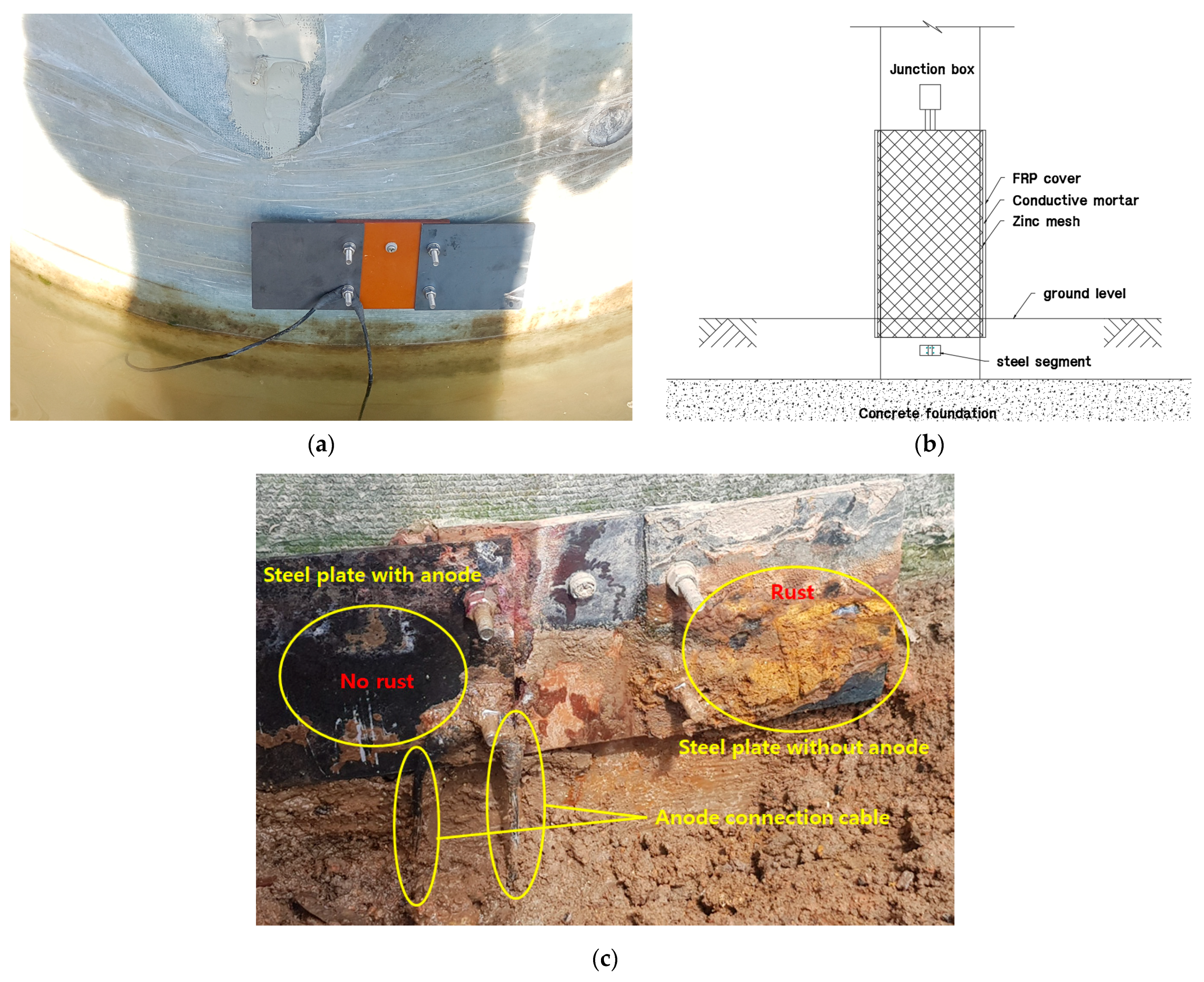
To support the hypothesis that CP workability is acceptable even if a few columns have depolarization potentials of less than 100 mV after four years, a visual inspection was conducted. Since the only way to visually check the corrosion and anticorrosion condition of the rebar embedded inside the concrete is through the coring, a separate segment was installed in the lower part of the pile, in order not to destroy the concrete, for checking the corrosion and protection status of the rebar. One segment was electrically connected to the sacrificial anode, and the other segment was exposed to the corrosive environment without being connected to the sacrificial anode. As shown in Figure 11, after four years, it can visually confirm the results that the steel segment under CP does not exhibit corrosion, while the segment without protection shows significant corrosion. This indicates that the CP of the target bridge effectively prevented corrosion.
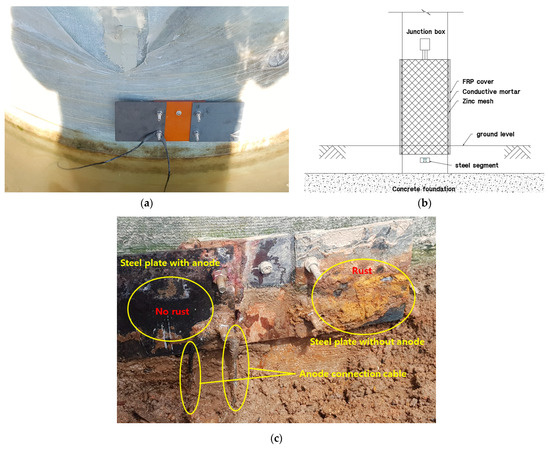
Figure 11.
Noncorroded steel segment before CP operation (a), location of steel segment (b), and results of visual inspection of corrosion with and without CP (c).
The results of the depolarization potential and visual inspection are discussed below. If the steel is surrounded by seawater or underground, sustainable protection exists under low resistivity. This can result in a consistent depolarization potential of 100 mV or higher. However, in concrete, which has high resistivity, the measured depolarization potential may not consistently exceed 100 mV, depending on the measurement environment. The target bridge, located in an area where it is exposed to tidal fluctuations twice a day, faces challenges in achieving a depolarization potential exceeding 100 mV when the structure dries out after the seawater level recedes. In such cases, it is presumed that the corrosion of the reinforcement in the structure is halted or reduced. On the one hand, during high tide when the structure is submerged in seawater, depolarization potential exceeding 100 mV is expected, indicating no issues with protection. Moreover, several piers had depolarization potentials of less than 100 mV. In this case, the amount of activated carbon in the conductive mortar can be adjusted to allow more conductivity, resulting in an enhanced current flow. Therefore, the amount of activated carbon could be adjusted depending on the surrounding environment under the condition that the physical properties of conductive mortar satisfy the standards.
The results of the pilot test demonstrated the feasibility of the conductive mortar application to the SACE system. Further investigations of actual marine structures can be performed with different amounts of conductive mortar to determine whether the amount of activated carbon plays a key role in the variation in CP performance.
6. Conclusions
In this study, the effectiveness of conductive mortar on an SACP system was evaluated for an actual bridge structure. Basic property tests for the conductive mortar were conducted in the laboratory based on the criteria outlined in KS F 4042 for polymer cement mortar used in the maintenance of concrete structures. After installing the SACP system in the bridge structure, depolarization potential measurements and visual inspection were performed over four years to check the performance of the SACP system with conductive mortar. The results of the study led to the following conclusions:
- The conductive mortar satisfied the criteria for basic property tests. Although both the compressive and flexural strengths results measured up to 28 days tended to decrease with increasing admixture amounts, the test results ensured satisfactory quality for on-site construction for all proposed amounts of activated carbon. The conductive mortar demonstrated both basic properties and durability and secured effective performance for the intended application.
- Through depolarization potential measurements, although the performance of SACP decreased slightly with time, SACP with conductive mortar showed superior performance to that with general mortar. Some partial protection was observed after four years; however, this does not mean that it is not protected at all. This is not thought to be a problem because the amount of depolarization can be changed depending on the specific resistivity of the concrete, such as rain, humidity, and weather.
- Visual inspection of the test specimens with the CP system revealed no corrosion after four years, whereas significant corrosion was observed in the unprotected specimens. This additional confirmation indicates that the CP system operated well, even if there were some possibilities of partial protection in some columns.
This study represents the first application of conductive mortar in Korea using the SCAP method. Over the course of four years and seven measurements, satisfactory CP performance was confirmed. The conductive mortar containing 5% activated carbon satisfied all the required criteria for electrical conductivity, durability, and other properties that the mortar should exhibit. Furthermore, it is anticipated that this conductive mortar can be applied to various fields beyond bridges, including harbors, dams, and underground structures, which will be investigated in future studies.
Author Contributions
Conceptualization, J.-M.H., C.J. and J.-A.J.; methodology, J.-M.H., C.J. and J.-A.J.; investigation, J.-M.H., C.J. and J.-A.J.; writing—original draft preparation, J.-M.H.; writing—review and editing, C.J. and J.-A.J.; visualization, J.-M.H. and C.J. All authors have read and agreed to the published version of the manuscript.
Funding
This research received no external funding.
Institutional Review Board Statement
Not applicable.
Informed Consent Statement
Not applicable.
Data Availability Statement
Data are contained within the article.
Conflicts of Interest
Author Ji-Myung Ha was employed by the company Conclinic E&C Co., Ltd. The remaining authors declare that the research was conducted in the absence of any commercial or financial relationships that could be construed as a potential conflict of interest.
References
- Byrne, A.; Holmes, N.; Norton, B. State-of-the-art review of cathodic protection for reinforced concrete structures. Mag. Concr. Res. 2016, 68, 664–677. [Google Scholar] [CrossRef]
- Zhou, Y.; Gencturk, B.; Willam, K.; Attar, A. Carbonation-induced and chloride-induced corrosion in reinforced concrete structures. J. Mater. Civ. Eng. 2015, 27, 04014245. [Google Scholar] [CrossRef]
- Page, C. Mechanism of corrosion protection in reinforced concrete marine structures. Nature 1975, 258, 514–515. [Google Scholar] [CrossRef]
- Jeong, J.-A.; Jin, C.-K.; Kim, Y.-H.; Chung, W.-S. Electrochemical performance evaluation of corrosion monitoring sensor for reinforced concrete structures. J. Adv. Concr. Technol. 2013, 11, 1–6. [Google Scholar] [CrossRef]
- Erdogan, C.; Swain, G. Conceptual sacrificial anode cathodic protection design for offshore wind monopiles. Ocean Eng. 2021, 235, 109339. [Google Scholar] [CrossRef]
- Jeong, J.-A.; Jin, C.-K. The effect of temperature and relative humidity on concrete slab specimens with impressed current cathodic protection system. J. Adv. Mar. Eng. Technol. (JAMET) 2013, 37, 260–265. [Google Scholar] [CrossRef]
- Erdogan, C.; Swain, G. The effects of biofouling and corrosion products on impressed current cathodic protection system design for offshore monopile foundations. J. Mar. Sci. Eng. 2022, 10, 1670. [Google Scholar] [CrossRef]
- Zhou, H.; Xu, Y.; Peng, Y.; Liang, X.; Li, D.; Xing, F. Partially corroded reinforced concrete piers under axial compression and cyclic loading: An experimental study. Eng. Struct. 2020, 203, 109880. [Google Scholar] [CrossRef]
- Guo, A.; Li, H.; Ba, X.; Guan, X.; Li, H. Experimental investigation on the cyclic performance of reinforced concrete piers with chloride-induced corrosion in marine environment. Eng. Struct. 2015, 105, 1–11. [Google Scholar] [CrossRef]
- Yuan, W.; Guo, A.; Li, H. Experimental investigation on the cyclic behaviors of corroded coastal bridge piers with transfer of plastic hinge due to non-uniform corrosion. Soil Dyn. Earthq. Eng. 2017, 102, 112–123. [Google Scholar] [CrossRef]
- Schmitt, G.; Schütze, M.; Hays, G.F.; Burns, W. Global needs for knowledge dissemination, research, and development in materials deterioration and corrosion control. World Corros. Organ. 2009, 38, 14. [Google Scholar]
- Koch, G. Cost of corrosion. In Trends in Oil and Gas Corrosion Research and Technologies; Elsevier: Amsterdam, The Netherlands, 2017; Volume 2017, pp. 3–30. [Google Scholar]
- Pedeferri, P. Cathodic protection and cathodic prevention. Constr. Build. Mater. 1996, 10, 391–402. [Google Scholar] [CrossRef]
- de Rincon, O.T.; Hernández-López, Y.; de Valle-Moreno, A.; Torres-Acosta, A.A.; Barrios, F.; Montero, P.; Oidor-Salinas, P.; Montero, J.R. Environmental influence on point anodes performance in reinforced concrete. Constr. Build. Mater. 2008, 22, 494–503. [Google Scholar] [CrossRef]
- Christodoulou, C.; Glass, G.; Webb, J.; Austin, S.; Goodier, C. Assessing the long term benefits of Impressed Current Cathodic Protection. Corros. Sci. 2010, 52, 2671–2679. [Google Scholar] [CrossRef]
- Cheng, X.; Xia, J.; Wu, R.-J.; Jin, W.-L.; Pan, C.-G. Optimisation of sacrificial anode cathodic protection system in chloride-contaminated reinforced concrete structure. J. Build. Eng. 2022, 45, 103515. [Google Scholar] [CrossRef]
- Van Belleghem, B.; Maes, M.; Soetens, T. Throwing power and service life of galvanic cathodic protection with embedded discrete anodes for steel reinforcement in chloride contaminated concrete. Constr. Build. Mater. 2021, 310, 125187. [Google Scholar] [CrossRef]
- Bertolini, L.; Redaelli, E. Throwing power of cathodic prevention applied by means of sacrificial anodes to partially submerged marine reinforced concrete piles: Results of numerical simulations. Corros. Sci. 2009, 51, 2218–2230. [Google Scholar] [CrossRef]
- Bertolini, L.; Gastaldi, M.; Pedeferri, M.; Redaelli, E. Prevention of steel corrosion in concrete exposed to seawater with submerged sacrificial anodes. Corros. Sci. 2002, 44, 1497–1513. [Google Scholar] [CrossRef]
- Kranc, S.; Sagues, A.A.; Presuel-Moreno, F.J. Computational and experimental investigation of cathodic protection distribution in reinforced concrete marine piling. In Proceedings of the Corrosion97; NACE International: Houston, TX, USA, 1997. [Google Scholar]
- Presuel-Moreno, F.; Kranc, S.; Sagues, A. Cathodic prevention distribution in partially submerged reinforced concrete. Corrosion 2005, 61, 548–558. [Google Scholar] [CrossRef]
- Jeong, J.-A.; Jin, C.-K.; Chung, W.-S. Tidal water effect on the hybrid cathodic protection systems for marine concrete structures. J. Adv. Concr. Technol. 2012, 10, 389–394. [Google Scholar] [CrossRef]
- Jeong, J.; Jin, C. Experimental studies of effectiveness of hybrid cathodic protection system on the steel in concrete. Sci. Adv. Mater. 2014, 6, 2165–2170. [Google Scholar] [CrossRef]
- García, Á.; Schlangen, E.; van de Ven, M.; Liu, Q. Electrical conductivity of asphalt mortar containing conductive fibers and fillers. Constr. Build. Mater. 2009, 23, 3175–3181. [Google Scholar] [CrossRef]
- Fu, X.; Chung, D. Carbon fiber reinforced mortar as an electrical contact material for cathodic protection. Cem. Concr. Res. 1995, 25, 689–694. [Google Scholar] [CrossRef]
- Hou, J.; Chung, D. Cathodic protection of steel reinforced concrete facilitated by using carbon fiber reinforced mortar or concrete. Cem. Concr. Res. 1997, 27, 649–656. [Google Scholar] [CrossRef]
- Bertolini, L.; Bolzoni, F.; Pastore, T.; Pedeferri, P. Effectiveness of a conductive cementitious mortar anode for cathodic protection of steel in concrete. Cem. Concr. Res. 2004, 34, 681–694. [Google Scholar] [CrossRef]
- Xu, J.; Yao, W. Current distribution in reinforced concrete cathodic protection system with conductive mortar overlay anode. Constr. Build. Mater. 2009, 23, 2220–2226. [Google Scholar] [CrossRef]
- Jing, X.; Wu, Y. Electrochemical studies on the performance of conductive overlay material in cathodic protection of reinforced concrete. Constr. Build. Mater. 2011, 25, 2655–2662. [Google Scholar] [CrossRef]
- Carmona, J.; Garcés, P.; Climent, M. Efficiency of a conductive cement-based anodic system for the application of cathodic protection, cathodic prevention and electrochemical chloride extraction to control corrosion in reinforced concrete structures. Corros. Sci. 2015, 96, 102–111. [Google Scholar] [CrossRef]
- Zhao, R.; Tuan, C.; Xu, A.; Fan, D. Conductivity of ionically-conductive mortar under repetitive electrical heating. Constr. Build. Mater. 2018, 173, 730–739. [Google Scholar] [CrossRef]
- Seo, D.-J.; Lee, Y.-J.; Choi, B.-G.; Park, J.-G.; Heo, G.-H. Study on Heating Performance and Flexural Strength Properties of Electrically Conductive Mortar. Appl. Sci. 2023, 13, 9903. [Google Scholar] [CrossRef]
- Ha, J.-M.; Jeong, J.-A.; Jin, C. Development of Conductive Mortar for Efficient Sacrificial Anode Cathodic Protection of Reinforced Concrete Structures—Part 1: Laboratory Experiments. Appl. Sci. 2022, 12, 12056. [Google Scholar] [CrossRef]
- KS F 4042; Polymer Modified Cement Mortar for Maintenance in Concrete Structure. KSA: Seoul, Republic of Korea, 2017.
- Mercuri, M.; Vailati, M.; Gregori, A. Lime-based mortar reinforced with randomly oriented polyvinyl-alcohol (PVA) fibers for strengthening historical masonry structures. Dev. Built Environ. 2023, 14, 100152. [Google Scholar] [CrossRef]
- NACE RP 0290-90; Cathodic Protection of Reinforced Steel in Concrete Structure. NACE: Houston, TX, USA, 1990.
- ASTM C876-15; Standard Test Method for Corrosion Potentials of Uncoated Reinforcing Steel in Concrete. ASTM International: West Conshohocken, PA, USA, 2015.
- ASTM G5-14; Standard Reference Test Method for Making Potentiodynamic Anodic Polarization Measurements. ASTM International: West Conshohocken, PA, USA, 2014.
- ACI Committee 222; C.o.M.i.C. Protection of Metals in Concrete Against Corrosion. ACI: Washington, DC, USA, 2001.

Disclaimer/Publisher’s Note: The statements, opinions and data contained in all publications are solely those of the individual author(s) and contributor(s) and not of MDPI and/or the editor(s). MDPI and/or the editor(s) disclaim responsibility for any injury to people or property resulting from any ideas, methods, instructions or products referred to in the content. |
© 2024 by the authors. Licensee MDPI, Basel, Switzerland. This article is an open access article distributed under the terms and conditions of the Creative Commons Attribution (CC BY) license (https://creativecommons.org/licenses/by/4.0/).