Article

Strength Analysis of Cylindrical Shells with Tangential Nozzles under Internal Pressure

College of Mechanical and Electrical Engineering, Beijing University of Chemical Technology, Beijing 100029, China
*
Author to whom correspondence should be addressed.
Appl. Sci. 2024, 14(6), 2363; https://doi.org/10.3390/app14062363
Submission received: 30 January 2024 / Revised: 1 March 2024 / Accepted: 8 March 2024 / Published: 11 March 2024
(This article belongs to the Special Issue Advances in Structural Optimization)

Abstract

:
Pressure vessels having the structure of a cylindrical shell with a tangential nozzle are often used in engineering for some process requirements. But there are no accurate methods in engineering codes for the strength design of this special structure. In this paper, the limit–load analysis was performed to evaluate the weakening effects of the tangential nozzles on the strength of the cylindrical shells under internal pressure. A so-called strength–weakening coefficient was defined to reflect the weakening degree of the load-bearing capacity of the cylindrical shells by the tangential nozzles or specifically by the three dimensionless structural parameters, namely diameter ratio (do/Di), diameter-thickness ratio (Di/T) and thickness ratio (t/T). Results show that when increasing do/Di and Di/T or decreasing t/T, the strength–weakening coefficient increases, which means that the strength–weakening effect of the tangential nozzle on the cylindrical shell increases. With sufficient simulation results, regression equations for the strength–weakening coefficient were obtained which provides a reference for the strength design of cylindrical shells with tangential nozzles under internal pressure.

1. Introduction

The pressure vessel is a closed container under pressure. In certain processes, it is necessary to install tangential nozzles on the pressure vessels. Compared to the conventional orthogonal nozzle configuration, the stress distribution in pressure vessels with tangential nozzles becomes more complex and exhibits a more severe stress concentration [1]. However, there are currently no suitable design specifications or codes available for the opening structure of tangential nozzles on the cylinder shells.
With advancements in finite element technology, numerous scholars have conducted extensive research on pressure vessel openings using the limit–load method for analysis purposes. Johnson et al. [2] employed elastic–plastic finite element analysis to conduct parametric studies encompassing a wide range of vessel geometries and materials; they proposed a novel model capable of accurately predicting burst strength in both thin-walled and thick-walled pressure vessels. Wang H F et al. [3] employed the elastic–plastic large deflection analysis method and nonlinear finite element analysis to determine the bursting pressure and fracture location at the intersection of the oblique nozzle and cylindrical shell. Skopinskii et al. [4] utilized the finite element inelastic analysis method to investigate the connection structure between the nozzle and shell. The findings reveal that the ultimate load of radial oblique nozzles is significantly lower than that of radial nozzles. Additionally, parametric analysis results demonstrate the influence of nozzle inclination angle and diameter ratio on the ultimate load value. Prakash et al. [5] analyzed variations in ultimate pressure for cylindrical pressure vessels with a nozzle when the inclination angle of the nozzle in the longitudinal and radial planes is changed by employing an elastic–plastic limit–load method, which holds significance for optimizing pressure vessel design.
Focusing on parametric analysis of nozzle structures, Tang et al. [6] designed three dimensionless parameters (do/Di, t/T and Di/T) and conducted a limit–load-based parametric study on cylinder radial nozzles under compound loads, obtaining an empirical equation describing their ultimate load relationship under such conditions through regression analysis to solve for their bearing capacity, effectively within the shells’ radial nozzles context. Xu Xinyi [7] examined four dimensionless parameters (circumferential nozzle inclination angle β, opening ratio d/D, wall thickness ratio δet/δe and diameter-to-thickness ratio D/δe) influencing ultimate pressure in circumferential nozzle structures with cylindrical shells while designing an orthogonal test model for further regression analysis and fitting a formula for the limit load. Xue [8] not only investigated the relationship between various geometric parameters (d/D, D/T and t/T) and blasting pressure, but also derived the corresponding equations. Additionally, four different materials were employed to validate the proposed equations. Focusing on the open nozzle structure of cylindrical shells under external pressure, Zhang Shuling [9] systematically examined the variation pattern of critical pressure Pcr under different opening ratios d/D, nozzle-to-cylinder thickness ratio δet/δe, cylinder diameter-to-thickness ratio Do/δe and cylinder length-to-diameter ratio L/Do through finite element nonlinear buckling analysis. Zhang Jinwu [10] conducted finite element analysis on orthotropic titanium cylindrical shells with perforated nozzle structures. The results revealed that as δet/δe, D/δe and L/D decrease, the weakening effect of the opening ratio ρ on the Pcr of the cylindrical shell increases. A regression equation for critical instability pressure Pcr was obtained through regression analysis. Fan Hangchao [11], by utilizing machine learning technology and redeveloping an ABAQUS plug-in toolset, developed a prediction model for nozzle connections in pressure vessels. This model enables rapid prediction of local stress at the nozzle joint by inputting parameters such as radius and wall thickness of both cylinder and nozzle (R, r, T, t; mm), as well as nozzle inclination (a; °). It provides a reliable and convenient platform for swift evaluation and optimization of pressure vessel designs.
As for the pressure vessel design by analysis, there are three methods based on numerical simulations for protection against collapse: (a) Elastic Stress Analysis Method—Stresses are computed using an elastic analysis and classified into categories. (b) Limit–Load Method—A calculation is performed to determine a lower bound to the limit load of a component. (c) Elastic–Plastic Stress Analysis Method—A collapse load is derived from an elastic–plastic analysis, considering both the applied loading and deformation characteristics of the component. Wang X M [12] compared the difference between the Elastic Stress Method and the plastic Limit–Load Method in evaluating static strength and shakedown. Majid Movahedi Rad [13] discussed the principles of Elasto–Plastic shakedown analysis and limit analysis and emphasized the greater difficulty in the practical application of shakedown analysis. Compared with the Elastic Stress Analysis Method, the Limit–Load Method is more straightforward without setting stress classification lines and performing stress categories. And compared with the Elastic–Plastic Stress Analysis Method, the Limit–Load Method may be more conservative without considering the strain–strength property of the material. Of course, as a nonlinear analysis, computation based on the Limit–Load Method is hard to converge, especially for a large structure.
In this paper, a limit–load analysis was performed to evaluate the weakening effects of the tangential nozzles on the strength of the cylindrical shells under internal pressure. The strength–weakening coefficient was defined to reflect the weakening degree of the load-bearing capacity of the cylindrical shells by the tangential nozzles or specifically by the three dimensionless structural parameters do/Di, Di/T and t/T. Regression equations for the strength–weakening coefficient were obtained, which provides a reference for the strength design of cylindrical shells with tangential nozzles under the internal pressure.

2. Establishment of Finite Element Models

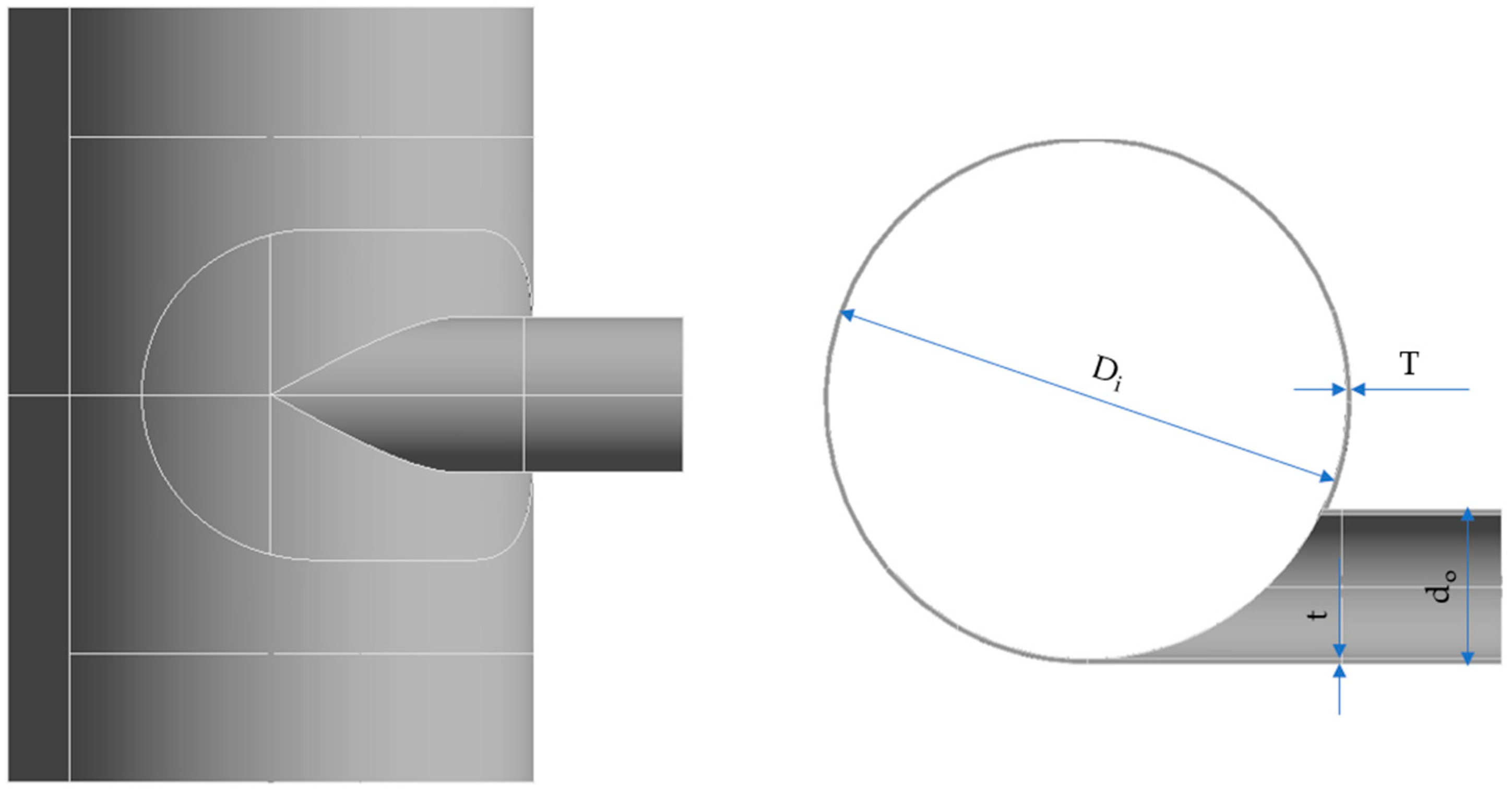
2.1. Geometric Model
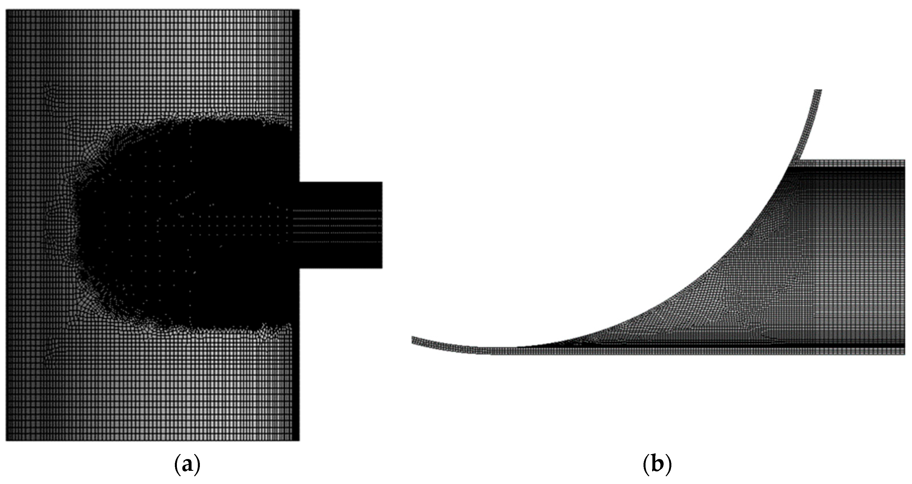
The structure analyzed in this paper was composed of a cylinder and a tangential nozzle. The cylinder material was Q345R with a yield strength of 283.5 MPa, and the nozzle material was 20# steel with a yield strength of 210 MPa [14]. According to GB150.2-2011 [15], the material performance parameters are shown in Table 1.
The ideal elastic–plastic model is generally used in the limit–load analysis. In this finite element method, the bilinear isotropic Hardening (BISO) model based on the von Mises yield criterion, associated flow criterion and small displacement theory built in ANSYS Workbench 21 R1 was adopted. The tangent modulus was set to 0 [16], and the yield strength of the cylinder and nozzle material was set, respectively (as listed in Table 1 and shown in Figure 1).
The finite element geometric model is shown in Figure 2. In this study, Di is the inner diameter of the cylindrical shell, T is the wall thickness of the cylindrical shell, do is the outer diameter of the nozzle and t is the wall thickness of the nozzle. The extension length of the cylinder and the nozzle were much larger than the requirement of the edge stress attenuation length [17].
Focusing on the tangential nozzle structure of the cylindrical shell and keeping the inner diameter of the cylinder Di = 1000 mm unchanged, the models were established by changing three dimensionless parameters (the diameter ratio of nozzle to cylinder 0.1 ≤ do/Di ≤ 0.3, the thickness ratio of nozzle to cylinder 0.5 ≤ t/T ≤ 1.75 and the diameter thickness ratio of cylinder 71.43 ≤ Di/T ≤ 125) for the numerical simulations. The range of structural parameters investigated in this study generally aligns with the size range of typical tangential nozzle structures in engineering. The dimensionless parameters are shown in Table 2. A total of 120 finite element analysis models were established by using the full factor analysis method.

2.2. Mesh Model

The limit–load analysis is a material nonlinear problem. Considering that the structure of the connection part of the tangential nozzle is discontinuous and even sharp changes occur, in order to ensure the stability of the numerical solution, the meshing requirements are higher. Here, the three-dimensional solid high-order element (solid186) provided by ANSYS Workbench 2021 R1 software was used for meshing. At the same time, local mesh refinement was performed in the connection area of the tangential nozzle and the cylinder to improve the accuracy of the calculation results. The mesh model is shown in Figure 3. For the model with do/Di = 0.3, t/T = 1 and Di/T = 100, the total number of elements is 235,805, and the total number of nodes was 1,089,252.

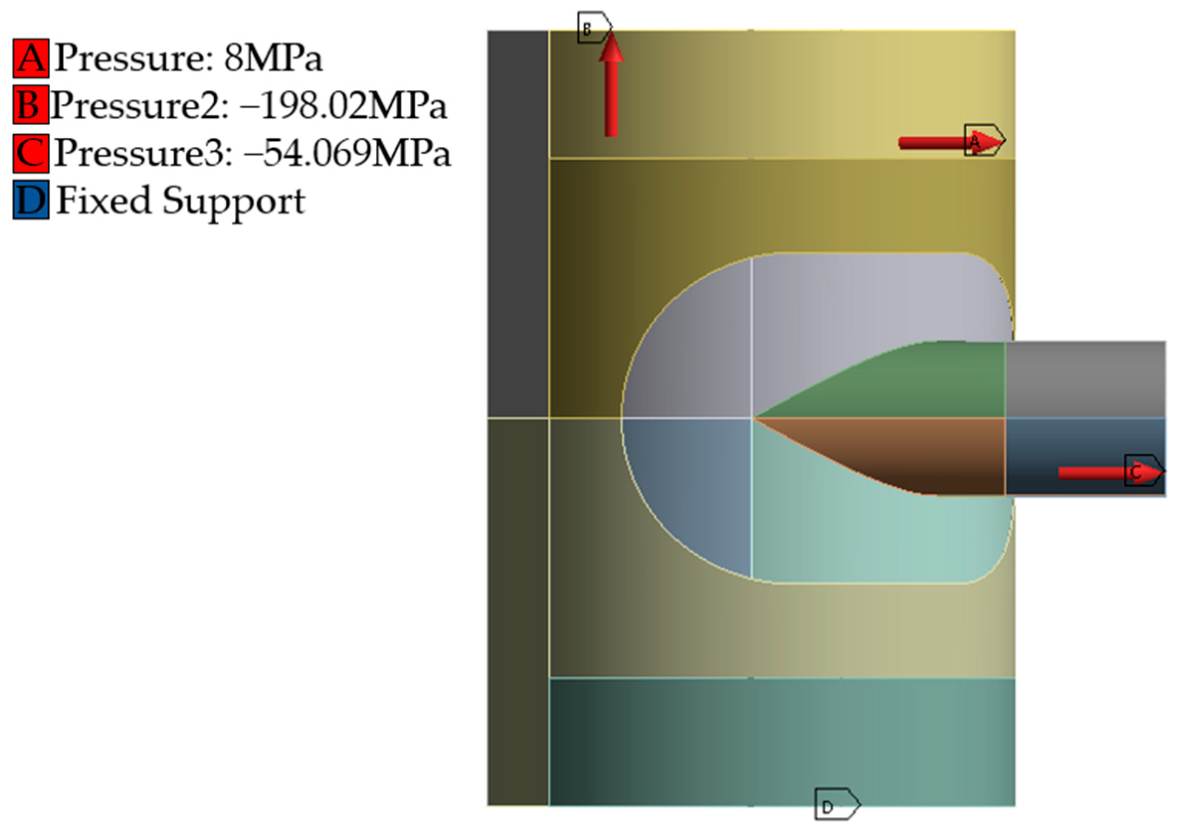
2.3. Loads and Constraints

The fixed support was applied to the lower end of the cylindrical shell, internal pressure was applied to all inner surfaces of the model, an equivalent axial tensile stress was applied to the upper end of the cylindrical shell, and the equivalent nozzle stress was applied to the nozzle end, as illustrated in Figure 4.

3. Limit–Load Analysis

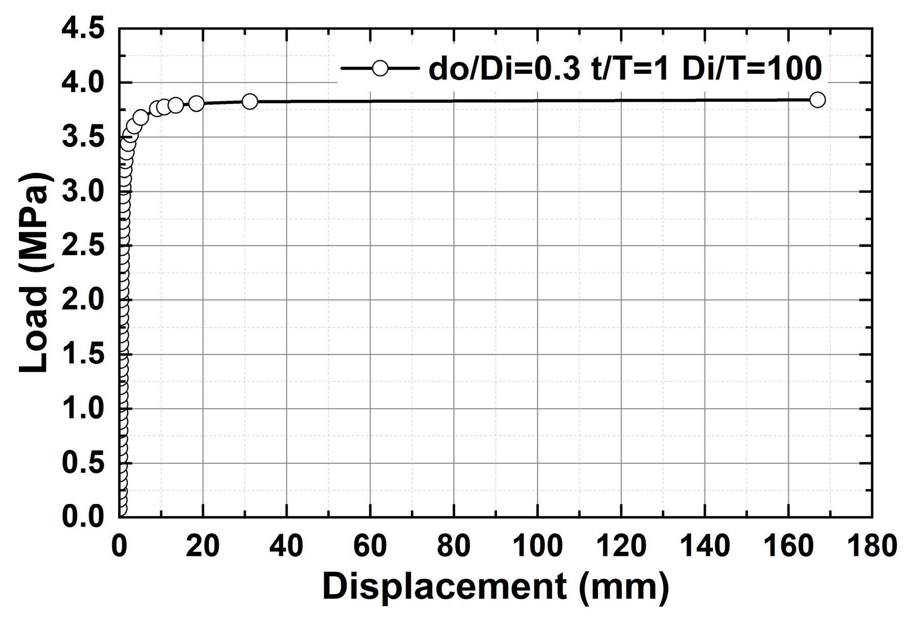
3.1. Limit–Load Analysis Method

The advantage of the limit–load analysis method is it can directly obtain the maximum limit–load that the structure can withstand to prevent plastic collapse. Limit–load analysis is a plastic mechanics problem based on three assumptions: (1) the material is an ideal elastic–plastic; (2) the structure is in a small deformation state; and (3) it adheres to the Mises yield condition and its related flow criterion. The novelty of the limit–load method lies in its ability to directly compute the maximum pressure that a structure can withstand based on a given material and structural parameters. The solution involves gradually applying loads to the structure from an initial zero-stress state to the extreme value (i.e., the limit load) where collapse occurs when adding even a little more load.

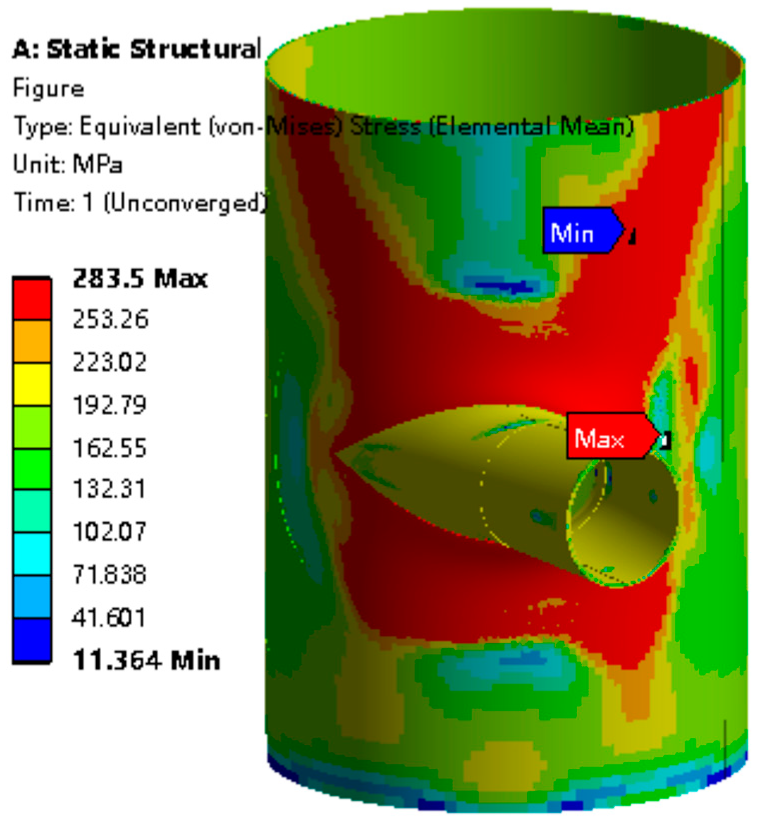
3.2. Results of Limit–Load Analysis

The limit load for a cylindrical shell without a nozzle is primarily determined by the maximum pressure exerted on the shell. This critical load depends not only on the material strength but also on the diameter and thickness of the shell. It can be derived from analyzing the von Mises stress or the circumferential stress induced by internal pressure. Through the finite element calculation, the limit load of four groups of cylindrical shell models without nozzles is obtained as listed in Table 3, and the von Mises stress value in the limit state is also listed in the table [18]. It can be seen that the von Mises stresses are very close to the yield strength of the model with a relative error of less than 2%, indicating that the limit–load calculation is accurate.
As an example, Figure 5 is the displacement–load curve of a given structure in the limit–load analysis process. The displacement–load curve serves as a numerical treatment method for determining the attainment of ultimate load, showcasing the relationship between load and displacement in the finite element model as load steps increase. If the slope of the curve during the horizontal stage is less than 1/100th of the elastic slope, it can be inferred that the limit load has been reached. Figure 5 demonstrates convergence in the finite element calculation results, indicating the achievement of the limit state.
The von Mises stress contours of the structure corresponding to Figure 5 under the limit load are depicted in Figure 6. It is evident that the region where yield first occurs and the limit load is controlled primarily lies on the inner surface of the cylinder in the connection area between the tangential nozzle and cylindrical shell.
Figure 7 shows the variation in the limit load of the cylindrical shell having a tangential nozzle with the structural parameters. Obviously, in the range of the designed parameters, with the increase in Di/T, the limit–load value decreases significantly. Keeping Di/T unchanged, with the increase in t/T and the decrease in do/Di, or in other words, the larger the wall thickness and the smaller the outer diameter of the tangential nozzle, the greater the limit load of the cylindrical shell with the tangential nozzle or the stronger the bearing capacity of the structure is, as a result of a less weakening degree of the tangential nozzle on the strength of the cylindrical shell.

3.3. Strength–Weakening Coefficient and Its Influence Factors

In order to quantitatively characterize the influence of tangential nozzles on the ultimate load-bearing capacity of cylindrical shells under internal pressure, a so-called strength–weakening coefficient is defined as follows:
K = ( P 0 P ) / P 0 × 100 %
In the formula, P0 and P are the limit load of the cylindrical shell without a nozzle and the cylindrical shell with a tangential nozzle, respectively. Obviously, the greater the strength–weakening coefficient, the greater the influence of the tangential nozzle on the load-bearing capacity of the cylindrical shell. The strength–weakening coefficient of the cylindrical shell having tangential nozzles with different diameter ratios do/Di, thickness ratios t/T and diameter-thickness ratios Di/T under internal pressure is shown in Figure 8, Figure 9 and Figure 10.
It is seen from Figure 8 that the strength–weakening coefficient of the cylindrical shell with tangential nozzles decreases monotonously with increasing relative thickness t/T for different do/Di and Di/T, meaning the thicker the nozzle is, the smaller the weakening effect of the nozzle on the load-bearing capacity of the cylindrical shell is.
It can be seen from Figure 9 that with the increase in do/Di, the strength–weakening coefficient K shows an increasing trend. But when t/T is small, i.e., the thickness of the nozzle wall is small, with the increase in do/Di, the increasing trend of the K value gradually slows down, meaning the influence gradually becomes less significant.
It is seen from Figure 10 that, with the increase in Di/T, the strength–weakening coefficient K increases monotonically. With increasing do/Di and decreasing t/T, or with the increase in the diameter of the nozzle and the decrease in the wall thickness of the nozzle, the K value increases significantly, i.e., the load-bearing capacity of the cylindrical shell decreases greatly.
Specifically, when do/Di = 0.30, t/T = 0.50 and Di/T = 125, the strength–weakening coefficient reaches 61.52%, meaning the load-bearing capacity of the cylindrical shell is significantly decreased. But when do/Di = 0.10, t/T = 1.75 and Di/T = 71.43, the strength reduction coefficient is close to 0, meaning the load-bearing capacity of the cylindrical shell is not obviously affected by the tangential nozzle.

4. Regression of the Strength–Weakening Coefficient

In this section, equations for the strength–weakening coefficient K of cylindrical shells were regressed as functions of the variables do/Di, t/T and Di/T in order to facilitate the strength design of cylindrical shells with tangential nozzles under internal pressure.

4.1. Regression of the Strength–Weakening Coefficient

On the basis of a large number of numerical calculation results, the regression analysis of the strength–weakening coefficient is carried out by using Origin 2024 software. After comparing the accuracy of various regression models, the regression equations were finally obtained as follows:
When t/T = 0.50~1, do/Di = 0.10~0.20,
K = 2.745 + 231.846 × d o D i + 0.135 × D i T 32.182 × t T + 21.349 × ( t T ) 2 + 0.678 × d o D i × D i T 146.111 × d o D i × t T 0.000500 × ( D i T ) 2 × t T
When t/T = 0.50~1, do/Di = 0.20~0.30,
K = 16.892 + 149.395 × d o D i + 0.192 × D i T 53.683 × t T + 17.055 × ( t T ) 2 0.0422 × D i T × t T + 0.204 × d o D i × D i T × t T 18.742 × d o D i × ( t T ) 2
When t/T = 1~1.75, do/Di = 0.10~0.20,
K = 12.724 + 215.284 × d o D i + 0.115 × D i T 120.213 × d o D i × t T + 0.493 × ( t T ) 3 + 0.548 × ( d o D i ) 2 × D i T + 0.00252 × d o D i × ( D i T ) 2 + 14.674 × d o D i × ( t T ) 2 0.000317 × ( D i T ) 2 × t T
When t/T = 1~1.75, do/Di = 0.20~0.30,
K = 11.378 + 193.955 × d o D i + 0.179 × D i T 0.138 × t T 117.899 × d o D i × t T 0.0499 × D i T × t T + 1.078 × ( d o D i ) 2 × D i T + 22.246 × d o D i × ( t T ) 2

4.2. Numerical Verification of Regression Equations of the Strength–Weakening Coefficient

In order to validate the accuracy and applicability of the regression equation for the strength–weakening coefficient, four finite element models are redesigned within the dimensionless parameter range corresponding to the formula. Both regression equation calculations and the finite element limit–load analyses are performed and compared. The results are shown in Table 4. It can be seen that the results of the regression equations calculation and the finite element simulation agree well with each other with a relative difference of less than 4%, meaning the equations are accurate enough for engineering application.

4.3. Applicability of the Regression Equations of the Strength–Weakening Coefficient for Different Shell Diameters

The previous finite element analysis and limit–load calculations are based on the cylindrical shell diameter Di = 1000 mm but, due to the use of dimensionless parameters, the results are applicable to other shell diameters.
Table 5 shows the calculation results where do/Di, t/T and Di/T are the same, but the shell diameters are 500 mm, 1000 mm and 2000 mm. It is seen that for the cylinder without nozzles when the diameter-thickness ratio Di/T is kept constant but the diameter Di is changed, the limit–load value is unchanged, which is 6.48 MPa. For the cylinder shells with tangential nozzles, when do/Di, t/T and Di/T are the same, the limit load and the strength–weakening coefficient are basically the same when changing the shell diameter Di, and the relative error between the finite element solution and the formula solution for the strength–weakening coefficient is within 4%. Therefore, for the tangential nozzle structure with different shell diameters, the strength design method is also applicable when the three variables do/Di, t/T and Di/T are within the applicable range specified in this paper.

5. Conclusions

In this paper, the limit–load analysis was performed to evaluate the weakening effects of the tangential nozzles on the strength of the cylindrical shells under internal pressure. Conclusions were drawn as follows:
(1)
For the strength design of cylindrical shell structure with tangential nozzles, in view of the fact that there is no accurate strength design method, this paper proposes a limit–load analysis approach based on a finite element method.
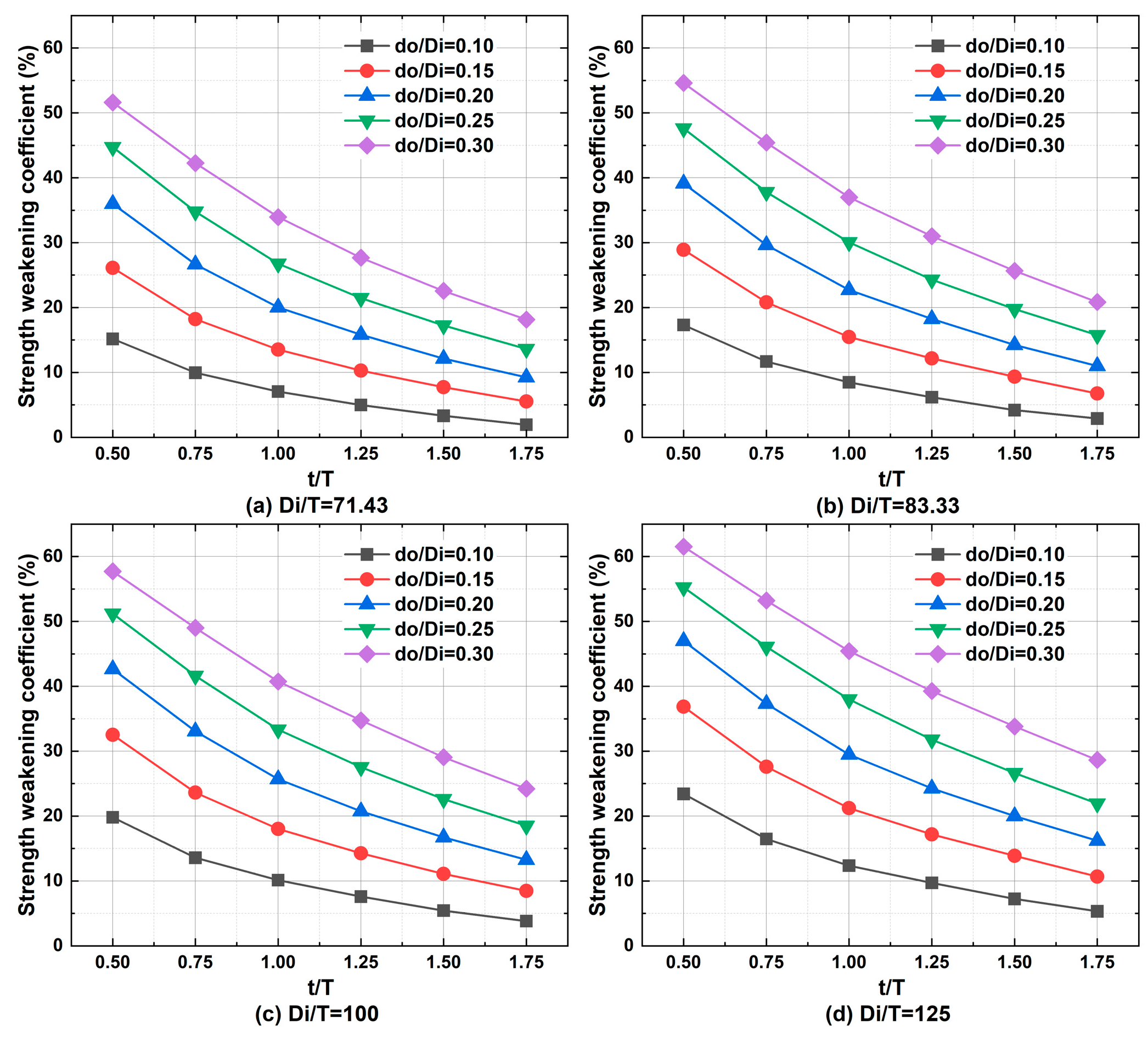
(2)
The weakening degree of the ultimate load-bearing capacity of cylindrical shells with tangential nozzles was defined as the strength–weakening coefficient and the influence of do/Di, t/T and Di/T was studied. It was found that with increasing do/Di and Di/T and decreasing t/T, the strength–weakening coefficient increases or, in other words, the ultimate load-bearing capacity of the cylindrical shell decreases.
(3)
With sufficient numerical calculation of the ultimate load-bearing capacity of the cylindrical shell with tangential nozzles under internal pressure, the regression equation of the strength–weakening coefficient was obtained which was numerically verified for accuracy. Clearly, by providing the formulas for strength evaluation, this work delves deeper into the subject compared to other similar studies in the literature and yields more practical outcomes.
(4)
Due to the use of dimensionless parameters, the regression equation is suitable for different shell diameters with a tangential nozzle structure. The regression equations of the strength–weakening coefficient provide a reference way for the strength design of cylindrical shell structures with tangential nozzles under internal pressure.
It should be pointed out that in this study, only internal pressure was considered. If there are no tube forces on the end of the tangential nozzles or the tube forces are significantly smaller than the equivalent nozzle force induced by the pressure, Equations (2)–(5) are valid and have reference values for the strength design of cylindrical shell structures with tangential nozzles under internal pressure. But if the tube forces on the end of the tangential nozzles are large and cannot be neglected, the results obtained in this paper are not meaningful and the equations should be modified.

Author Contributions

Conceptualization, C.Q. and Z.W.; Data curation, X.Z.; Formal analysis, X.Z. and C.Q.; Investigation, X.Z.; Methodology, C.Q. and Z.W.; Project administration, C.Q. and Z.W.; Software, X.Z.; Supervision, C.Q. and Z.W.; Validation, X.Z. and C.Q.; Writing—original draft, X.Z.; Writing—review and editing, C.Q. and Z.W. All authors have read and agreed to the published version of the manuscript.

Funding

This research received no external funding.

Institutional Review Board Statement

Not applicable.

Informed Consent Statement

Not applicable.

Data Availability Statement

The original contributions presented in the study are included in the article, further inquiries can be directed to the corresponding author.

Conflicts of Interest

The authors declare no conflicts of interest.

References

  1. Wang, D.B.; Wei, X.L.; Xiang, S.; Guo, C.X.; Liu, H. Stress analysis for tangential bonded structure of pressure vessel and pipe based on finite element method. J. Hunan Inst. Eng. 2005, 29–33. [Google Scholar] [CrossRef]
  2. Johnson, W.R.; Zhu, X.-K.; Sindelar, R.; Wiersma, B. A parametric finite element study for determining burst strength of thin and thick-walled pressure vessels. Int. J. Press. Vessel. Pip. 2023, 204, 104968. [Google Scholar] [CrossRef]
  3. Wang, H.F.; Sang, Z.F.; Xue, L.P.; Widera, G.E.O. Burst Pressure of Pressurized Cylinders With Hillside Nozzle. J. Press. Vessel Technol. 2009, 131, 041204. [Google Scholar] [CrossRef]
  4. Skopinskii, V.N.; Berkov, N.A.; Stolyarova, N.A. Elasto-Plastic Deformation of a Pressure Vessel with a Nonradial Branch Pipe and Determination of the Limit Load. J. Mach. Manuf. Reliab. 2018, 47, 507–515. [Google Scholar] [CrossRef]
  5. Prakash, A.; Raval, H.K.; Gandhi, A.; Pawar, D.B. Plastic Limit Load Analysis of Cylindrical Pressure Vessels with Different Nozzle Inclination. J. Inst. Eng. Ser. C 2016, 97, 163–174. [Google Scholar] [CrossRef]
  6. Tang, Q.H.; Liu, K.; Sang, Z.F.; Li, C. Parametric analysis for limit load of cylindrical shell with radial nozzle under combined loadings. Chem. Eng. Mach. 2020, 47, 192–200. [Google Scholar]
  7. Xu, X.Y. The Research on Strength Analysis for Cylindrical Shell with Hillside Nozzle Structure under Internal Pressure. Master’s Thesis, Nanjing Tech University, Nanjing, China, 2014. [Google Scholar]
  8. Xue, L.; Widera, G.E.O.; Sang, Z. Parametric FEA Study of Burst Pressure of Cylindrical Shell Intersections. J. Press. Vessel Technol. 2010, 132, 031203. [Google Scholar] [CrossRef]
  9. Zhang, S.L.; He, X.H. Research on elastic buckling critical pressure of cylindrical shell with nozzle structure. Mach. Des. Manuf. 2017, 21–24. [Google Scholar] [CrossRef]
  10. Zhang, J.W.; He, X.H. Research on critical buckling pressure of orthotropic titanium cylindrical shell with nozzle structure. Press. Vessel Technol. 2020, 37, 20–26+35. [Google Scholar]
  11. Fan, H.C.; Hu, L.N. Pressure vessel nozzle local stress prediction software based on ABAQUS- machine learning. SoftwareX 2023, 24, 101550. [Google Scholar] [CrossRef]
  12. Wang, X.M.; Yan, D.S.; Xia, S.Q.; Guo, X.H. Application of limiting load method in stress analysis—Six important issues about stress analysis design for pressure vessels (Ⅳ). Petro-Chem. Equip. Technol. 2016, 37, 1–5+7. [Google Scholar]
  13. Majid, M.R. A Review of Elasto-Plastic Shakedown Analysis with Limited Plastic Deformations and Displacements. Period. Polytech. Civ. Eng. 2018, 62, 812–817. [Google Scholar]
  14. Zuo, A.D. Discussion of evaluation method for limit load analysis by using ANSYS. Process Equip. Pip. 2020, 57, 1–7. [Google Scholar]
  15. GB/T 150.2-2011; Pressure vessels—Part 2: Materials. Standards Press of China: Beijing, China, 2012.
  16. Bai, H.Y.; Fang, Y.L. ANSYS limit load analysis method in pressure vessel design. Press. Vessel Technol. 2014, 31, 47–50. [Google Scholar]
  17. Nadarajah, C.; Mackenzie, D.; Boyle, J.T. Limit and shakedown analysis of nozzle/cylinder intersections under internal pressure and in-plane moment loading. Int. J. Press. Vessel. Pip. 1996, 68, 261–272. [Google Scholar] [CrossRef]
  18. Wen, H.B.; Fu, L.; Yang, H.L.; Liu, Y. Stability analysis for the pressure vessel with special tangential nozzle. J. Sichuan Univ. Sci. Eng. (Nat. Sci. Ed. ) 2013, 26, 54–57. [Google Scholar]
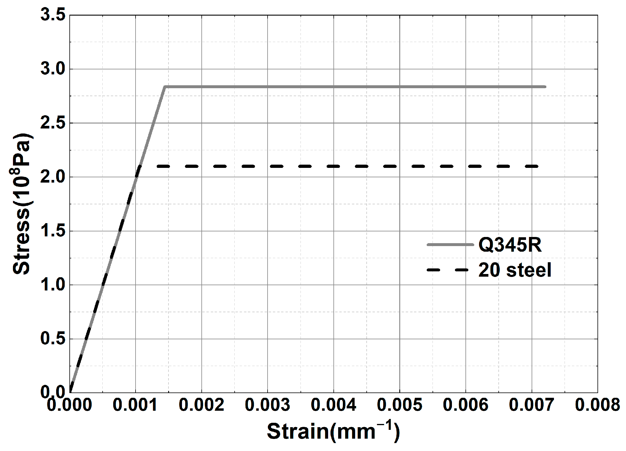
Figure 1. Ideal elastic–plastic numerical model.
Applsci 14 02363 g001
Figure 2. Three-dimensional geometric model of the cylindrical shell structure with a tangential nozzle.
Applsci 14 02363 g002
Figure 3. Finite element mesh model of the cylindrical shell with a tangential nozzle (do/Di = 0.3, t/T = 1, Di/T = 100). (a) Overall. (b) Local.
Applsci 14 02363 g003
Figure 4. Schematic diagram of the load and constraint application (do/Di = 0.3, t/T = 1, Di/T = 100).
Applsci 14 02363 g004
Figure 5. Displacement–load curve of the cylindrical shell with a tangential nozzle for limit–load analysis (do/Di = 0.3, t/T = 1, Di/T = 100).
Applsci 14 02363 g005
Figure 6. Contours of the von Mises stress at the cylindrical shell with a tangential nozzle under the limit load (do/Di = 0.3, t/T = 1, Di/T = 100).
Applsci 14 02363 g006
Figure 7. Change in the limit load value of the cylindrical shell having a tangential nozzle with t/T for different do/Di and Di/T.
Applsci 14 02363 g007
Figure 8. Change in strength–weakening coefficient K of the cylindrical shell structure having tangential nozzles with t/T for different do/Di and Di/T.
Applsci 14 02363 g008
Figure 9. Change in strength–weakening coefficient K of the cylindrical shell structure having a tangential nozzle with do/Di for different t/T and Di/T.
Applsci 14 02363 g009
Figure 10. Change in strength–weakening coefficient K of the cylindrical shell structure having a tangential nozzle with Di/T for different do/Di and t/T.
Applsci 14 02363 g010
Table 1. Material properties.
MaterialThickness/mmDesign Temperature/°CAllowable Stress/MPaYield Strength/MPaTangential Modulus/MPaElastic Modulus/MPaPoisson’s SpecificDensity
/kg·m−3
Q345R3~16100189283.50197,0000.37850
20>16~401001402100197,0000.37850
Table 2. Values of dimensionless structure parameters for the finite element analysis models.
do/Dit/TDi/T
0.100.571.43
0.150.7583.33
0.201100
0.251.25125
0.301.5
1.75
Table 3. Limit–load value of the cylindrical shell without nozzles.
Di/TLimit Load/MPavon Mises Stress/MPa
71.439.040287.47
83.337.765286.94
1006.480286.22
1255.190285.42
Table 4. Verification of regression equations.
do/Dit/TDi/TLimit Load P/MPaThe Finite Element Solution of Strength–Weakening Coefficient K/%The Formula Solution of Strength–Weakening Coefficient K/%Relative Difference/%
0.130.890.915.9017.1817.100.50
0.270.8111.113.2145.0144.441.28
0.181.490.916.0914.4914.410.56
0.221.4111.114.5222.5422.301.05
Table 5. Limit load and strength–weakening coefficients of cylindrical shell structures with different shell diameters Di under the same dimensionless structure parameters.
do/Dit/TDi/TDi/mmT/mmLimit Load of Cylinder with Tangential Nozzle P/MPaLimit Load of a Cylinder P0/MPaThe Finite Element Solution of Strength–Weakening Coefficient K/%The Formula Solution of Strength–Weakening Coefficient K/%Relative Difference/%
0.100.7510050055.60006.4813.5813.882.23
1000105.60006.4813.5813.882.23
2000205.60806.4813.4613.883.17
0.250.5010050053.15896.4851.2550.132.19
1000103.16186.4851.2150.132.10
2000203.16946.4851.0950.131.88
0.151.2510050055.55316.4814.3013.982.25
1000105.55496.4814.2813.982.07
2000205.54026.4814.5013.983.59
0.301.510050054.58026.4829.3228.682.17
1000104.59626.4829.0728.681.34
2000204.59626.4829.0728.681.34
Disclaimer/Publisher’s Note: The statements, opinions and data contained in all publications are solely those of the individual author(s) and contributor(s) and not of MDPI and/or the editor(s). MDPI and/or the editor(s) disclaim responsibility for any injury to people or property resulting from any ideas, methods, instructions or products referred to in the content.

