Article

Impact of Laser Cavity Configurations and Pump Radiation Parameters on the Characteristics of High-Energy Yellow Raman Lasers Based on Potassium Gadolinium Tungstate Crystals

Laseroptek, 204 Hyundai I Valley, 31 Galmachi-ro, 244 Beon-gil, Jungwon-gu, Seongnam-si 13212, Gyeonggi-do, Republic of Korea
*
Author to whom correspondence should be addressed.
Appl. Sci. 2024, 14(6), 2412; https://doi.org/10.3390/app14062412
Submission received: 24 January 2024 / Revised: 22 February 2024 / Accepted: 11 March 2024 / Published: 13 March 2024
(This article belongs to the Section Optics and Lasers)

Abstract

:
In this paper, the influence of pump radiation parameters and laser resonator configurations on the characteristics of high-energy 589 nm KGW Raman lasers is investigated and explained. The best energy efficiency is obtained in lasers with a flat resonator, while the best angular characteristics are obtained in lasers with an unstable resonator. The use of stable spherical resonators results in the worst energy and angular characteristics. The angular divergence in lasers with flat cavities increases with pump intensity because of wing growth, whereas the core width remains unchanged. The structure of the wings is recorded and analyzed.

1. Introduction

The research and development of crystalline Raman yellow lasers currently is one of the mainstreams of solid-state laser technology. The most recent review [1] partially describes the progress in this field. The interest of most research groups at present is concentrated on Raman lasers, pumped by DPSS lasers and operating in CW mode or in pulse mode with a low pulse energy (typically less than 1 mJ) and a high pulse repetition rate, above 105 Hz. This tendency is confirmed in [1] as well as in the most comprehensive previous reviews [2,3]. Also, all these reviews only describe the numerous configurations and optical schemes of these lasers, but do not include important information about the relation between the Raman laser characteristics and the characteristics of pump radiation or the laser cavity configuration.
There are important applications (medical treatment, photography, etc.), which require yellow pulse bursts with a high (above 100 mJ) pulse energy. The generation of light bursts with multijoule energy at 589 nm by a Raman laser, based on a potassium gadolinium tungstate crystal (KGW), pumped by 532 nm radiation from a nanosecond Nd: YAG laser, was realized for the first time in our work [4]. The laser generated a 10 ms burst with a total energy of more than 10 J, consisting of 75–78 pulses with each pulse having a relatively high, 120–150 mJ, energy. Optimization and improvement of such lasers, first of all, requires optimizing the conditions for generating single high-energy pulses. In the present paper, we study the impact of the laser cavity configuration and pump radiation intensity on the characteristics of KGW Raman lasers, generating single nanosecond pulses at 589 nm with an energy of 100–300 mJ.
The typical pump spot size in low-energy lasers, reviewed in [1,2,3], is less than 0.2 mm. To generate high-energy pulses with a nanosecond duration without damaging the optical components, here, similar to in our previous work [4], we increased the pump spot size to several millimeters and produced pumping with spatially homogeneous 532 nm radiation. Subsequently, an over 100-fold increase in the Fresnel number results in significant changes to the laser cavity mode structure, which can affect both the energy and spatial characteristics of lasers.
The 589 nm radiation in this work, similar to [2,3,4], was selectively generated by cascade Raman conversion: 532 nm→559 nm (first Stokes order)→589 nm (second Stokes order). The 559 nm radiation is trapped inside a high-Q cavity and serves as a pump for 589 nm generation; only 589 nm radiation comes out from the cavity. The spatial characteristics of second Stokes generation via such a process and the influence of the cavity configuration on 589 nm radiation characteristics have not been studied previously.
It should be pointed out that some features of first Stokes order generation in crystalline Raman lasers with an increased Fresnel number were investigated in [5,6,7,8,9]. Unfortunately, the spatial characteristics in these publications are insufficiently presented, without important details and the required generalizations, and thus add little to the understanding of Raman laser operation.
In accordance with the above, we represent for the first time the results of a systematic study of the energy and spatial characteristics of yellow 589 nm generation in high-energy KGW Raman lasers, using flat, stable spherical and unstable cavities with different pump parameters and a relatively large pumping spot size.

2. Experimental Part

The experimental setup in this work is the same as in [4]. For the reader’s convenience, we describe some items in more detail here:
A flash-lamp-pumped electro-optically Q-switched Nd: YAG laser produced pulses of 532 nm radiation with a variable energy E532 at 1 Hz for Raman laser pumping. The pulse duration tP was 10.6 ns at E532 = 80 mJ and was reduced to 7.5 ns at E532 = 450 mJ. The maximum E532 was 500 mJ. The spectral width of the 532 nm radiation was less than 0.1 nm. Rectangular pump spots with a linear size of a1~4 mm and a2~2 mm, with an area of A1 = 0.18 and A2 = 0.045 cm2, were formed inside a 7 × 7 × 50 mm, “b”-axis–cut KGW crystal, using a combination of a microlens array (MLA) homogenizer and a condenser lens.
Figure 1 shows the fluence profile of the pumping beam in the focal plane of the condenser lens. One can observe almost a flat top profile without hot spots. The variations in the pump fluence over the pump spot area here do not exceed ±11%.
The external cavity of the Raman laser was formed by two mirrors: pump and output mirrors. The pump mirrors had a high (>94%) transmission at 532 nm and a high reflection (>99%) within 550–650 nm. For selective cascade generation of the second Stokes order, the output mirrors had a high reflection at 532 nm and 559 nm to create a high Q-factor resonator for the first Stokes order, and a high transmission (90–99%) at 589 nm. The mirrors were installed near the KGW crystal’s ends, so the cavity geometrical length was 52–54 mm. In all cavity configurations, we only used flat output mirrors. Plano-concave pump mirrors with radii of curvature of 2000 mm, 1000 mm, and 500 mm were used in stable spherical cavities. Plano-convex pump mirrors (2000 mm and 750 mm) were used in unstable cavities.
The Raman laser characteristics were measured at three levels of pump intensity for pump spots with the above spot size using: I532 = E532/(A × tP) = 120, 220, and 350 MW/cm2.
The laser energy was measured using a J-50-YAG pyroelectric energy sensor from Coherent. Beam intensity profiles were recorded using a CMOS-1.001-Nano camera and software from Cynogy Technologies (Duderstadt, Germany). The wavelengths of the Raman laser output radiation were monitored via a flame spectrometer from Ocean Insight.

3. Results and Discussion

3.1. Energy Characteristics

We found that the efficiency of 589 nm generation, η589 = (E589/E532) × 100%, was almost equal for pump spots of ~2 and ~4 mm. The difference did not exceed ±5% and can be attributed to the errors during the attenuation of E532 when setting the given I532 for minor (2 mm) spots. Table 1 represents the η589 data obtained for a 4 mm spot.
The maximum conversion efficiency was obtained in lasers with a flat cavity. Note that larger efficiencies (>62% with a flat cavity) could be obtained at I532 > 350 MW/cm2. In lasers with an unstable cavity, the efficiency was a little lower. However, in lasers with stable spherical cavities, the efficiency was considerably reduced in comparison with flat-cavity lasers. The lowest values of η589 were obtained with spherical cavities with mirrors with the lowest radius of curvature.
As the 589 nm radiation here is actually created by 559 nm radiation, we also measured the conversion efficiencies of 559 nm generation, η559 = E559/E532 × 100%, in different laser cavities with an output mirror optimized for 559 nm generation (a high reflection at 532 nm and 98% transmission at 559 nm). The results for the 4 mm spot are shown in Table 2.
A comparison of the results in Table 1 and Table 2 reveals very similar relations between the laser efficiency and the cavity configuration for 589 nm and 559 nm generation. Thus, we believe that the reduction in η589, in general, is caused by the worsening of the 532→559 nm conversion at the first stage of the cascade process (532→559→589 nm).
The worsening of the 532→559 nm conversion in the Raman laser with a spherical cavity can be explained, similar to [10], by the worse spatial overlap between the 532 nm pump radiation and 559 nm Stokes radiation. In our case, for a large spot size and a homogeneous pump, we can neglect the variation in the pump and Stokes field distribution along the resonator axis and only take into account the dependence of the Stokes field transversal distribution on the cavity configuration. The overlap is characterized by a normalized overlap integral of the Stokes and pump transverse intensity profiles [11]:
1/Aeff = (ʃ I532I559dA)/(ʃ I532dA)2
where integration is performed over the entire area A of the pumping beam. For a beam with a flat top intensity distribution, we can represent this integral in a more evident form:
1/Aeff = const × ʃʃ f559 (x, y) dx dy
where f559 (x, y) is the normalized 559 nm intensity distribution:
I559 (x, y) = I559 (max) × f559 (x, y); here f559 (x, y) ≤ 1.
We can observe that for a flat top distribution of the pumping radiation, the maximum value of 1/Aeff is obtained when the distribution of the Stokes radiation is also flat top, which can be realized in a flat cavity. Any spatial variation in the Stokes radiation intensity would reduce 1/Aeff. In stable spherical cavities with a large Fresnel number, the generation of high-order Gaussian (Laguerre–Hermite) modes predominates [10,12], resulting in less overlap with the pump radiation and a lower conversion efficiency.
At the same time, the spatial distribution of 589 nm radiation should be very similar to that of 559 nm due to the common laser cavity. Bearing in mind the narrow spectral width (<0.1 nm) of 532 nm radiation and the relatively small difference in wavelengths, we can expect that the spatial structure of 559 nm radiation should be “imprinted” [11] into 589 nm radiation. A good overlap should result in a high-efficiency 559 nm→589 nm conversion.
The worsening of the overlap between 532 nm and 559 nm fields in stable spherical cavities also can lead to an increase in the 559 nm generation threshold. The threshold pump intensity ITH at 532 nm depends on cavity losses and the effective gain [11] at 559 nm. We measured ITH in different Raman laser cavities with the same output mirror (98% transmission). Diffraction losses in flat and spherical cavities were small in comparison with transmission losses, so the relationships between different ITH values represent the relationships between the effective gain coefficients obtained in these cavities. The measurement results for the 4 mm pumping spot are shown in Table 3.
One can see that ITH is larger in spherical cavities than in flat cavities, and grows when the radius of the spherical mirror’s curvature is reduced. These results are consistent with the results in Table 2 and support the above explanation of the behavior of η559 and η589 in Raman lasers.
The diffraction losses in unstable cavities are larger than in flat cavities. The magnification coefficients, calculated using formulas [12] for cavities with convex mirrors (R2000 and R750), are 1.56 and 2.05, so there are additional light losses of 59% and 76%, respectively. We assume that the slightly larger ITH for lasers with unstable cavities than for those with a flat cavity is caused by these losses, whereas the effective gain in unstable cavities can be almost at the same level as in flat cavities. The exact answer can be obtained from the experiments, similar to that observed in [13].
While the results shown in Table 3 definitely show differences in the generation thresholds of lasers with different cavity configurations, the absolute values of ITH must be viewed with caution, because there are many factors that introduce uncertainty into the measurement results, such as cavity misalignment and the subsequent variation in the Stokes mode structure, the influence of residual reflection from KGW crystal faces, changing temporal shapes of Stokes pulses, etc.
Bearing in mind the results obtained with stable spherical cavities, we suppose that the appearance of even a weak positive thermal lens in a Raman crystal can lead to a reduction in the conversion efficiency of high-energy lasers. On the other hand, the influence of a thermal lens in the KGW crystal for lasers with a pump spot size of ~0.2 mm was investigated in [10,14]. It was shown that the appearance of a thermal negative lens in KGW causes a decrease in the generated Stokes power, which can be compensated for by using a positive lens in the cavity. The apparent discrepancy between our supposition and the results of [14] can be easily explained:
-
The appearance of a negative lens in low-energy lasers, when the spot size is ~0.2 mm, leads to the distortion of Stokes generation in the TEM00 mode, which results in an increase in diffraction losses and worsening of the overlap with the pump beam;
-
In high-energy lasers, the efficiency has a low sensitivity to the increase in diffraction losses due to a high gain. A negative lens (or the negative curvature of laser mirrors) does not reduce the uniformity of the Stokes transversal distribution or the overlap with the pump beam (see next paragraph).
From this point of view, KGW crystals have an advantage in comparison with most other Raman crystals [15] due to the negative temperature coefficient of the refraction index.
Preliminary experiments showed that the application of stable spherical cavities in Raman lasers also leads to worsening laser angular characteristics and lower beam pattern uniformity and reproducibility. Due to these reasons, we suppose that the application of spherical cavities in high-energy Raman lasers has no practical utility. This is why we only show the results obtained for lasers with flat and unstable cavities below.

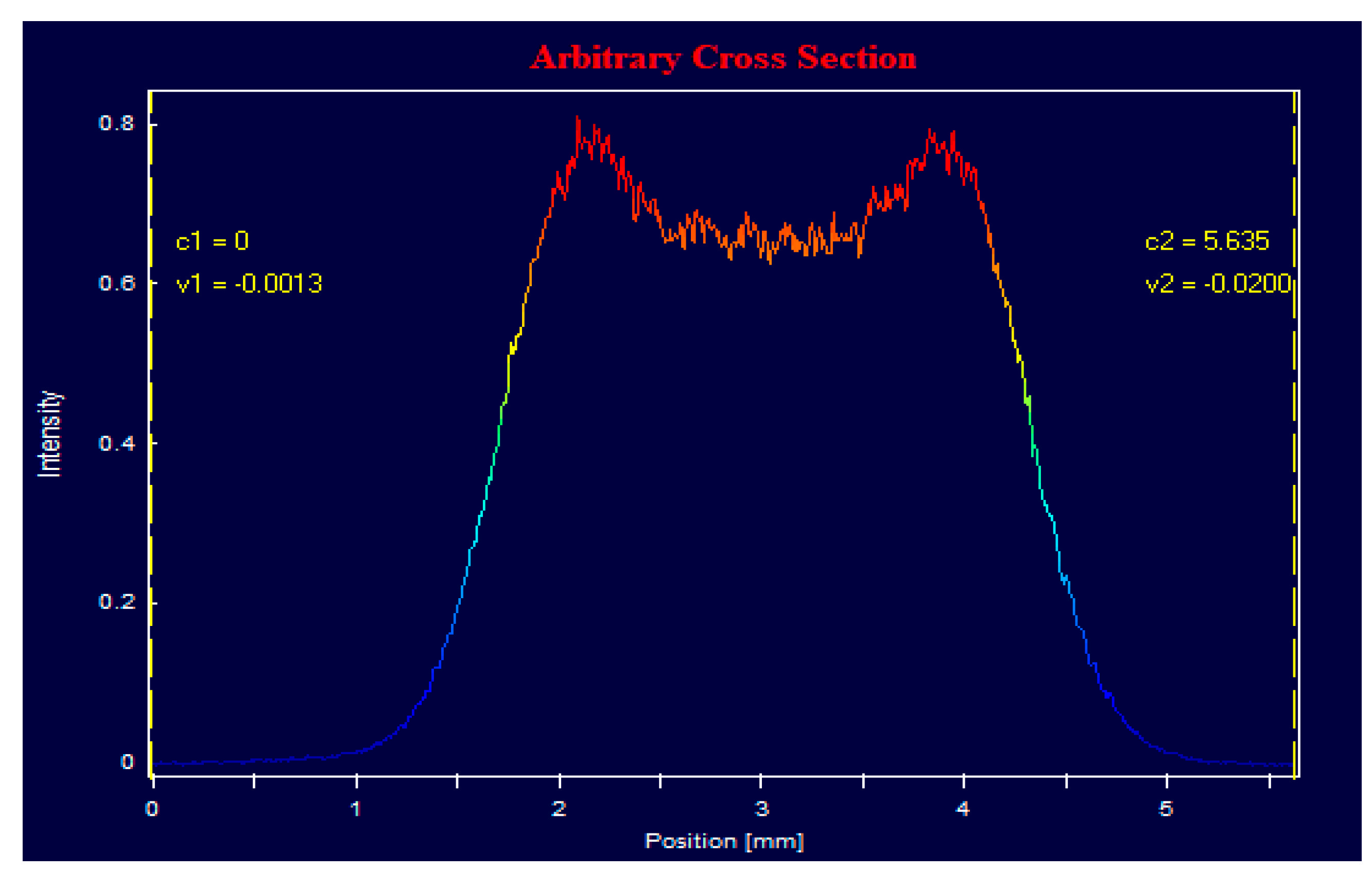
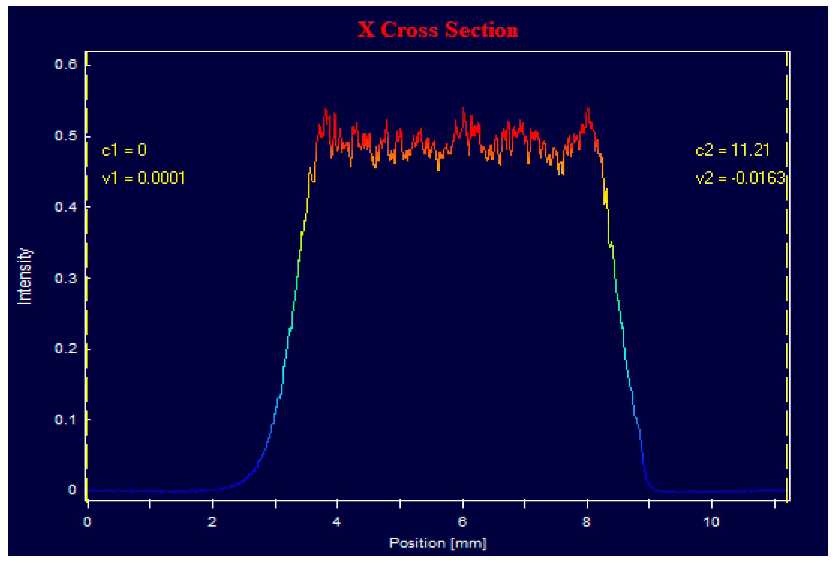
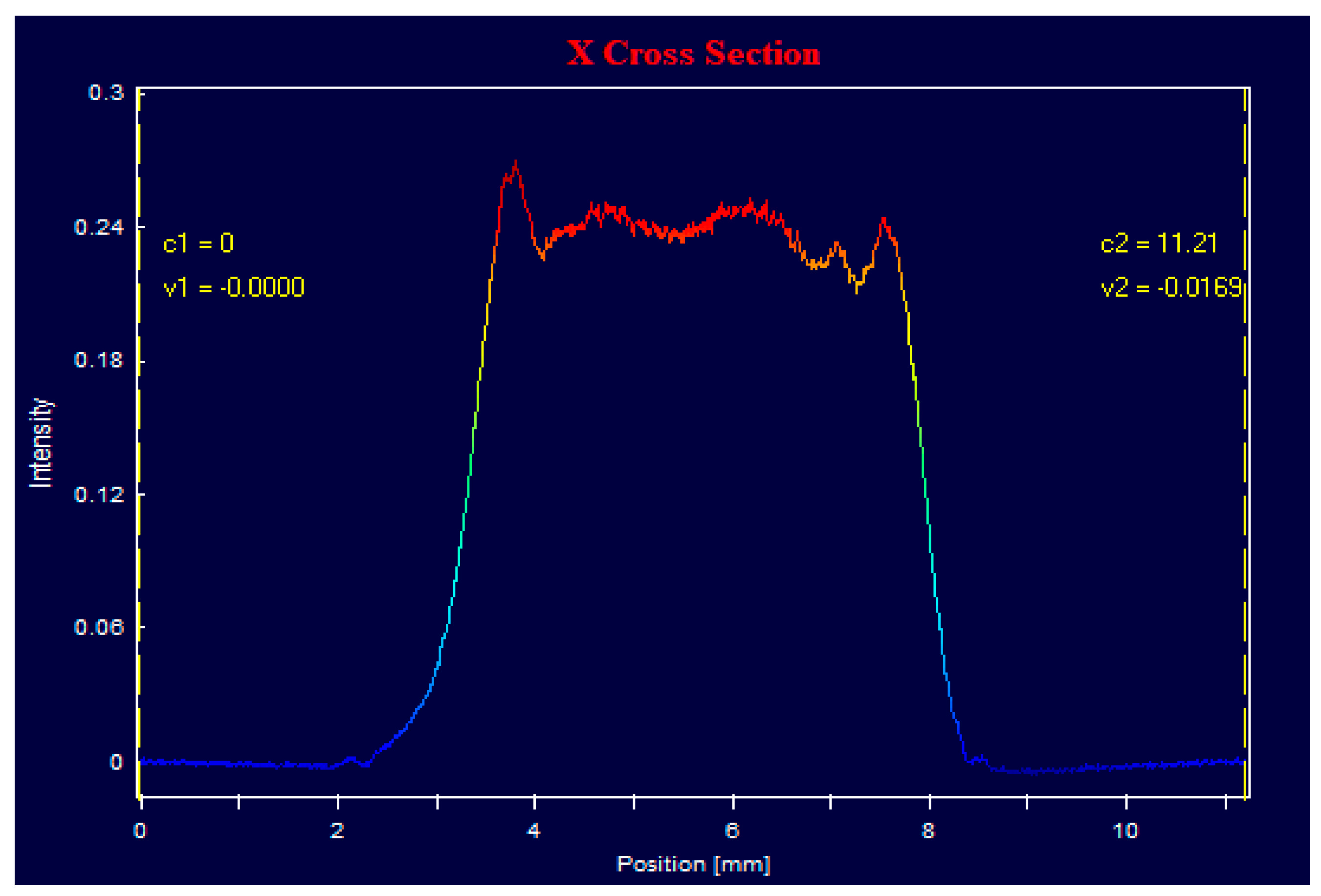
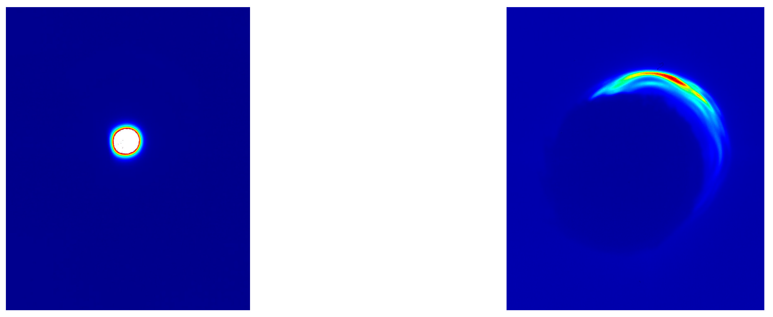
3.2. Near Field Uniformity

Figure 2 and Figure 3 show the 589 nm radiation fluence distribution at the output mirror at I589 = 220 MW/cm2. Both patterns have sharp edges and a good fluence distribution uniformity at the top. This is additional confirmation of the improved conversion efficiency in Raman lasers due to a better spatial overlap of the pump and Stokes radiation.

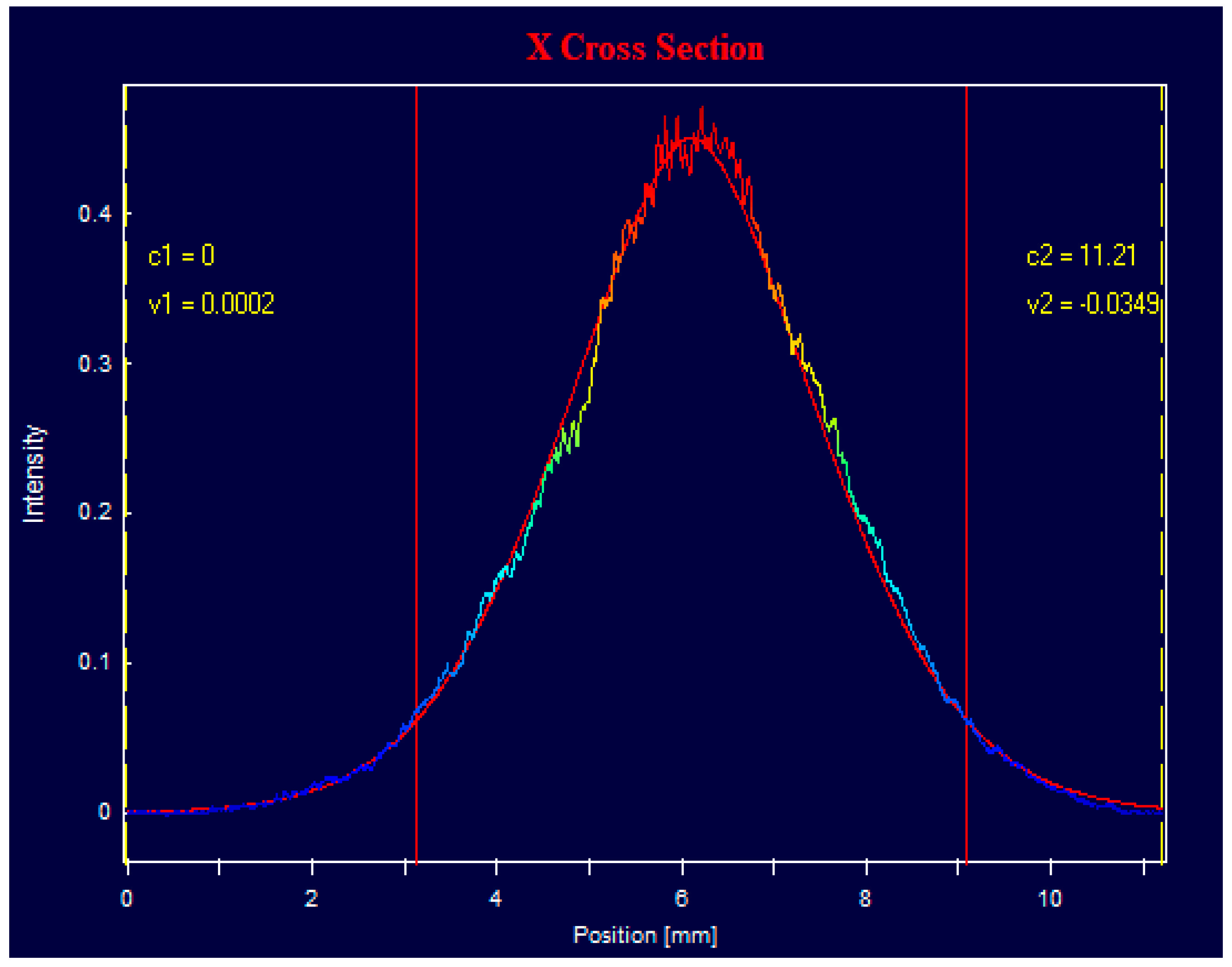
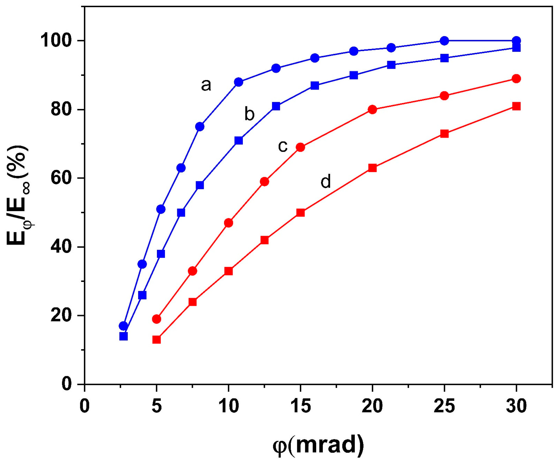
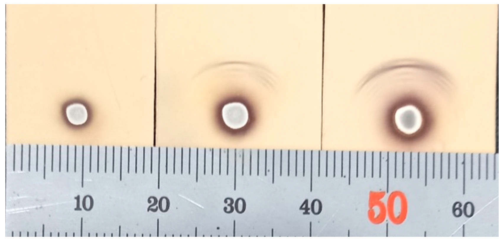
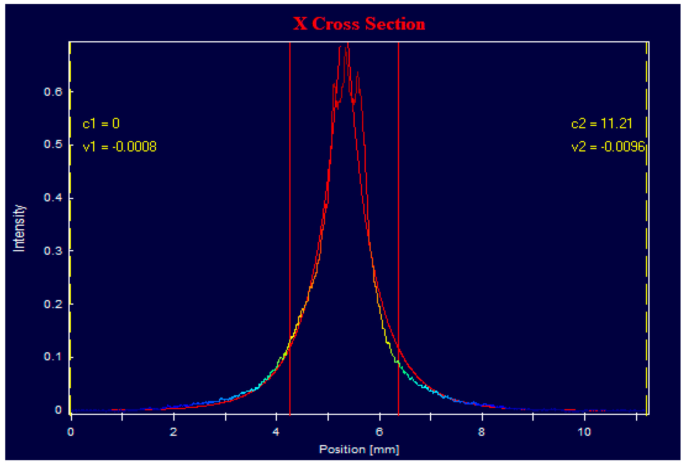
3.3. Angular Characteristics

To better characterize the Raman laser’s radiation angular distribution, we recorded the angular distribution of the radiation intensity (beam profile) and of the energy in the lens’s focal plane using a CMOS camera (Photonfocus, Lachen, Switzerland)beam profiler or a set of diaphragms in combination with a J-50-YAG energy sensor (Edmund Optics, Barrington, NJ, USA).

3.3.1. Laser with a Flat Cavity

The beam profile of the flat-cavity Raman laser when the pump spot size is ~4 mm recorded with a 400 mm lens is shown in Figure 4.
This profile fits a super-Gaussian distribution with the core width of 14.3 mrad (at 1/e2 level). A similar distribution with the core width of 13.3 mrad was observed at I532 = 120 MW/cm2.
The core width of the 2 mm pump spot was 8.0 mrad and remained almost unchanged within 120 MW/cm2 < I532 < 350 MW/cm2. The width variations did not exceed +/−2.5%.
The angular energy distribution is represented in Figure 5. The vertical axis shows the energy Eφ, irradiated within the angle φ, expressed as a percentage of the total laser energy E589.
Considering Figure 5, we note that the angular energy divergence of KGW Raman lasers (EKSMA Optics, Vilnius, Lithuania) is much larger than that of conventional lasers with a similar laser pump and cavity configuration. For example, in Ti:Sapphire lasers, even with a very short flat cavity (6.5 mm) and the same beam size (~4 mm), 80% of the energy propagates within an angle of 8 mrad, and the angular divergence does not depend on the pump energy density (or on pump intensity) [16]. However, in Raman lasers, at I532 = 120 MW/cm2, 80% of the laser energy propagates within 20 mrad; at I532 = 350 MW/cm2, this angle increases to 30 mrad.
A comparison of Figure 4 and Figure 5(c,d) shows that only 60% of the total E589 of the laser with a 4 mm pump spot is concentrated in the core (within an angle of 13.3 mrad) at I532 = 120 MW/cm2 and less than 50% (within an angle of 14.3 mrad) at 350 MW/cm2. For the laser with a 2 mm pump spot, 74% of the total E589 propagates within an 8 mrad core at 120 MW/cm2 and 57% at 350 MW/cm2 (Figure 5(a,b)). We observe that a large part of the radiation energy in all four cases is spread over the wings of the angular distribution. When the pump intensity increases, the angular size of the core remains almost unchanged, whereas the width of the angular energy distribution increases, mainly due to wing growth.
Note that when all radiation in the far field is distributed in accordance with a super-Gaussian function, then the energy within the core must exceed 88% of the total E589 [17].
All the results described above were obtained using an MLA with a numerical aperture of NA = 0.017 (NA = p/f, where p is the pitch and f is the focal length of the MLA). Figure 6 shows the angular energy distribution of the laser with a 4 mm pump spot at I532 = 350 MW/cm2, obtained using an MLA with different NA values (0.017 and 0.042). Within angles of 0–25 mrad, we observe an identical distribution for both NA values, but at angles larger than 25 mrad, the distributions begin to differ. About 10% of E589 is irradiated at angles larger than 65 mrad when NA = 0.042, while less than 2% is irradiated when NA = 0.017. Thus, an increase in NA causes an increase in the energy irradiated at large angles.
These results, in our opinion, indicate a different physical mechanism for the for wings, we took a more detailed recording of the laser’s far field when NA = 0.042.
The restricted dynamic range IMAX/IMIN of the camera sensor did not allow us to simultaneously record the radiation at the beam core and the wings. Figure 7, left, shows an overexposed 589 nm spot on the screen, placed in the focal plane of a 125 mm lens. The spot has sharp edges and a diameter of 2.5 mm, which corresponds to an angular size of 20 mrad. The light intensity outside this spot is much lower and is not recorded. To record the structure of the wings, we made a hole with a diameter of 14 mm in the screen, through which the main part of the laser beam energy can pass (dark circle in Figure 7, right). The hole is shifted in respect to the beam axis, so we can see a part of the structured wings on the screen.
For more detail, we observed the imprints made on photosensitive paper, shown in Figure 8. Here, we can observe:
A white overexposed spot with a diameter of ~2.5 mm, with a gray spot in the center of the overexposed area with a diameter of ~1.6–1.8 mm. The angular size of the gray spot is 13–15 mrad, so it can be attributed to the core of the beam profile in Figure 4; the angular size of the white spot (~20 mrad) corresponds to that of the sharp-edged spot in Figure 7, left, where the light intensity is much higher than that in the external area.
Multiple arcs with diameters of 10–16 mm and angular sizes of 80–130 mrad. During laser operation, they can be seen by the eye as bright yellow O-rings with an intensity varying in azimuth. We attribute them to the process of partially degenerative four-wave mixing (PDFWM), which accompanies Raman generation. A variety of parametric processes during stimulated Raman scattering in crystals has been studied theoretically in [18,19] and was observed in the experiments, in general, with picosecond pumping [20,21]. Under most experimental conditions, the PDFWM process dominated:
2 KI = KI+1 + KI−1
where KI is a wave vector of pump radiation and KI+1 and KI−1 are wave vectors of Stokes and anti-Stokes components. We believe that in our case, the 559 nm radiation also worked as a pump for PDFWM and produced Stokes radiation at 589 nm and anti-Stokes radiation at 532 nm. The latter was rejected by the highly reflective output mirror at 532 nm.
The intensity and geometry of the arcs generated in KGW crystals will depend on the angle between the axes of the crystal and KI direction. We suspect that the appearance of multiple arcs in our experiment was caused by the relatively large angle range of partial beams produced by MLA with an NA = 0.042. As a rule, we did not see the arcs when using an MLA with an NA = 0.017 when the crystal faces were aligned in parallel with the cavity mirrors and were normal to the pump beam axis. In this case, ~98% of the energy E589 was propagated within 65 mrad (Figure 6(a)). However, after an appropriate crystal tilt, we observed the appearance of isolated arcs even at NA = 0.017.
During high-intensity picosecond pumping, up to ~50% of the total energy from the Raman laser can be generated due to parametric conversion [21]. In our case, we estimated the energy generated by PDFWM, from Figure 6(b), as the energy irradiated at angles above 65 mrad. This energy was about 8–10% of E589 at I532 = 350 MW/cm2.
The origin of the radiation outside the white spot (besides parametric arcs) is not clear. The angular energy distribution shows that the energy irradiated at angles larger than 20 mrad may exceed 30% of E589. The beam profile core fits a super-Gaussian distribution and remains almost unchanged at large I532 values, whereas the E589 part, irradiated at large angles, increases. This is why we suppose that the energy of the wings cannot be attributed to the tails of the generated resonator modes. We suppose that this radiation may appear via scattering inside the laser cavity of the main 589 nm radiation and the subsequent amplification and irradiation of the scattered light within a plane angle Θ determined by the dimensions of the pump channel in the KGW crystal:
Θ = n × a/l
where n is the refraction index and l is the crystal length. For the a1 = 4 mm spot, we obtained Θ = 160 mrad. Thus, this radiation is irradiated into a solid angle, which is 40 times larger than the solid angle of the white spot. Supposing that this energy is 30% of the total E589 and has a uniform angular distribution, the average intensity of this radiation is calculated to be 80 times less than the average intensity within the white spot. It is not surprising that this radiation was not recorded at the imprints.
Undepleted single-pass gain increment in 50 mm KGW crystals at 589 nm under double-pass pumping at I532 = 350 MW/cm2 can be larger than 35, and it does not depend on the direction of light propagation. Tilted beams can undergo an even larger amplification than beams propagating in parallel to the cavity axis direction. A larger Raman gain coefficient and larger lateral dimensions of the pump channel in the crystal are advantageous for the amplification of tilted beams and wing growth.
Our supposition corresponds to the experimental results shown in Figure 5: we see that the angular energy divergence of the Raman laser increases with pump intensity, which is proportional to the Raman gain coefficient, and with an increase in the pump spot size (compare curves a-b for a 2 mm spot and c-d for a 4 mm spot). Also, when a KGW crystal with Brewster ends was used, the angular spread of laser radiation increased ~2-fold parallel to the polarization plane, in accordance with pump beam widening in the crystal, but the angular spread in the orthogonal direction remained unchanged.

3.3.2. Lasers with an Unstable Cavity

Radiation from Raman lasers with an unstable cavity in our case comes out through a flat output mirror in the form of a divergent spherical wave with a center of curvature located behind the pump mirror at a distance B from the output mirror. B can be calculated by the formula [12]: B = (L2 + LR)0.5 + L, where L is the optical length of the cavity and R is the radius of the pump mirror curvature. The output radiation can be collimated using a positive lens with a focal length F (larger than B) installed after the output mirror at a distance of d = F − B.
In our setup, the lateral size of the output beam increased due to the divergence before collimation from ~4 to ~8 mm, so the actual beam divergence was reduced 2-fold. For a fair comparison with the results obtained for a flat-cavity laser, where the beam size was ~4 mm, below, all angles for unstable-cavity lasers were increased 2-fold compared to those experimentally measured.
The beam profiles of Raman lasers with convex mirror radii of 750 mm and 2000 mm, recorded at I532 = 350 MW/cm2, are shown in Figure 9 and Figure 10.
Similar to that of the laser with a flat cavity, both intensity distributions at the core are close to a super-Gaussian distribution. The recalculated angular widths of the beam profile at 1/e2 level are 5.2 mrad for the laser with a 750 mm radius mirror and 10 mrad for the laser with a 2000 mm mirror. At I532 = 120 MW/cm2, the angular width of the 750 mm radius mirror remained unchanged, and was reduced to 7.6 mrad for the laser with a 2000 mm radius mirror. Thus, the angular core width of unstable-cavity lasers is 1.4–2.6 times less compared to flat-cavity lasers.
The angular energy distribution at I589 = 350 MW/cm2 is represented in Figure 11. We can see that the angular energy divergence of lasers with an unstable cavity reduces with a reduction in the radius of the mirror’s curvature. The divergence is 2–3 times less than that of lasers with a flat cavity (Figure 11(a)) depending on the convex mirror curvature.
Comparing the intensity and angular energy distributions at I532 = 350 MW/cm2, we can see that in unstable-cavity lasers, 56–58% of the total E589 is concentrated in the core, whereas in flat-cavity lasers, the core contains less than 50% of the total E589. Thus, use of an unstable cavity in KGW Raman lasers instead of a flat cavity results not only in a reduction in the core width, but also in a better concentration of the radiation energy within the core (in other words, a reduction in the wings).
Figure 12 shows the imprints of unstable-cavity laser radiation on photosensitive paper. To compensate for the above-mentioned two-fold reduction in angular divergence, the imprints were made in the focal plane of a lens with a two-fold larger focal length (250 mm) than used for Figure 8. We can see that the size of the imprints is much lower than in Figure 8, and the structure of the wings is also different. The lower influence of the scattered light on laser generation and the lower increase in the angular divergence in an unstable cavity, compared to a flat cavity, for conventional lasers were explained in [12]. The main reason for these effects is that the scattered radiation, which propagates at large angles to the axis, is removed from an unstable resonator more quickly and is subjected to lower amplification than in a flat resonator. In Raman lasers, we assume that the reason is similar. Also, it is clear that the efficiency of parametric generation under pumping by 559 nm divergent spherical waves, which takes place in an unstable resonator, should be less than under pumping by flat-like 559 nm radiation generated in a flat cavity. Both factors work together, leading to a reduction in the intensity and angular spread of the wings.
We are continuing to study and optimize Raman lasers with unstable cavities with the goal of obtaining angular divergence which is close to diffraction-limited divergence.

4. Conclusions

Here, we investigated the energy and spatial characteristics of high-energy yellow 589 nm KGW Raman lasers operating in single-pulse mode, as well as their dependence on pump intensity and the laser cavity configuration. The study shows the following:
  • The largest energy efficiency of KGW Raman lasers can be obtained with the use of a flat cavity. A slightly lower energy efficiency is observed with unstable cavities. Worse energy characteristics are obtained when using stable spherical cavities. The energy efficiency reduces with a reduction in the resonator mirror’s radius of curvature. This is explained by the worse lateral overlap between the pump radiation and Stokes radiation, because the spatial distribution of the Stokes radiation depends on the cavity configuration.
  • The best angular characteristics (lowest angular divergence) are obtained using unstable resonators. Lasers with flat cavities have a 2–3 times larger angular divergence, and worse characteristics are obtained with stable spherical cavities. We can conclude that stable spherical cavities in high-energy Raman lasers have no advantages, and there is no practical interest in their application.
  • A reduction in the mirror’s curvature in unstable-cavity lasers leads to a better angular divergence. At the same time, the energy efficiency is reduced. Thus, for a given laser application, optimization of the mirror’s curvature is required.
  • An increase in pump intensity leads to an increase in the angular energy divergence in lasers with all types of resonators. However, in lasers with flat cavities, the angular size of the core remains almost unchanged, and the angular energy divergence increases mainly due to wing growth. In lasers with unstable cavities, this process requires additional study.
Note that the angular characteristics of high-energy Raman lasers are much worse than those of conventional solid-state lasers. A 5.2 mrad angular core width, obtained in an unstable-cavity laser with a convex mirror of 750 mm, pumped at 350 MW/cm2, is 26 times larger, than the diffraction-limited value. The angular energy divergence of Raman lasers with a flat cavity is 2.5–3 times larger than that of Ti:Sapphire lasers under the same conditions. The main reason for this, in our opinion, is the very high gain level, which is typical of such Raman lasers but not achieved in most conventional lasers. A similar worsening of the angular characteristics in conventional lasers is observed in multistage pulsed oscillator–amplifier laser systems without interstage spatial filtering, where amplified spontaneous emission leads to inferior spatial and temporal contrasts.
Roughly speaking, we can consider the 589 nm radiation from KGW Raman lasers as a combination of two main components: radiation in the core and radiation in the wings. In our opinion, radiation in the wings does not represent the tails of resonator modes, especially at high pump intensities, but has another origin. Under some of the above-mentioned conditions, we observed signs of parametric generation, which contributes to part of the energy in the wings. Another contribution may be from the scattering of the core radiation with a subsequent strong amplification in the scattered radiation.
Note that, besides 589 nm radiation, we also observed weak radiation at 621 nm, generated in the form of straight and conical beams at pump intensities much lower than the threshold of third-order Stokes Raman generation. This radiation can be generated via secondary parametric processes, described theoretically in [16,17]. This radiation was very weak, with an energy of less than 0.1 mJ. Thus, such processes in practice are not important.
We intentionally did not use the M2 parameter to characterize the high-energy Raman laser beam quality. The determination of M2 is based on intensity profiles, and so it does not take into account the low-intensity radiation propagating in the wings at large angles to the beam axis. However, this radiation may contain a considerable part of the total energy, which is typical for high-energy Raman lasers. This is why, in this work, we combined intensity angular distribution measurements and angular energy distribution measurements at a given beam spot size. This allowed us to study the physical origin of high-energy 589 nm Raman laser angular divergence, which was one of the main aims of this paper.

Author Contributions

A.T. and H.C. contributed equally to this work. All authors have read and agreed to the published version of the manuscript.

Funding

This work was supported by the Technological Innovation R&D Program (S3272695), funded by the Ministry of SMEs and Startups (MSS, Republic of Korea).

Data Availability Statement

The data underlying the results presented at this paper are not publicly available at this time but may be obtained from the authors upon reasonable request.

Acknowledgments

The authors thank Park Gyu Tai for his help with preparing this paper’s figures.

Conflicts of Interest

Authors A.T. and H.C. were employed by the company, Laseroptek. The remaining authors declare that the research was conducted in the absence of any commercial or financial relationships that could be construed as a potential conflicts of interest.

References

  1. Jiang, P.; Ding, X.; Guo, J.; Zhang, H.; Qui, H.; Shang, Y.; Song, Z.; Wang, W.; Wang, C.; Liu, G.; et al. Research progress in crystalline Raman yellow lasers. Opt. Laser Technol. 2024, 169, 110072. [Google Scholar] [CrossRef]
  2. Cai, Y.; Ding, J.; Bai, Z.; Qi, Y.; Wang, Y.; Lu, Z. Recent progress in yellow laser: Principles, status and perspectives. Opt. Laser Technol. 2022, 152, 108113. [Google Scholar] [CrossRef]
  3. Pask, H.; Piper, J. Raman Lasers. In Handbook of Solid-State Lasers; Denker, B., Shklovsky, E., Eds.; Woodhead Publishing Limited: Cambridge, UK, 2013; pp. 493–524. [Google Scholar]
  4. Tarasov, A.; Chu, H. Wavelength conversion of multi-joule energy 532 nm pulse bursts via a potassium gadolinium tungstate Raman laser. Appl. Sci. 2023, 13, 10195. [Google Scholar] [CrossRef]
  5. Karpukhin, S.; Stepanov, A. Stimulated emission from the cavity under SRS in Ba(NO3)2, NaNO3 and CaCO3 crystals. Sov. J. Quantum Electron. 1986, 16, 1027–1031. [Google Scholar] [CrossRef]
  6. Basiev, T.; Danileiko, Y.; Doroshenko, M.; Osiko, V.; Fedin, A.; Gavrilov, A.; Smetanin, S. Powerful BaWO4 Raman laser pumped by a self-phase-conjugated Nd: YAG and Nd: GGG lasers. In Proceedings of the Advanced Solid-State Photonics 2004, Santa Fe, NM, USA, 1–4 February 2004; OSA: Washington, DC, USA, 2004. Paper TuB11. [Google Scholar]
  7. Ermolenkov, V.; Lisinetskii, V.; Mishkel, Y.; Grabchikov, A.; Chaikovskii, A.; Orlovich, V. A radiation source based on a solid-state Raman laser for diagnosing tropospheric ozone. Opt. Zhurnal 2005, 72, 39–44. [Google Scholar] [CrossRef]
  8. Chulkov, R.; Lisinetskii, V.; Lux, O.; Rhee, H.; Shrader, S.; Eichler, H.; Orlovich, V. Thermal aberrations and high-power frequency conversion in a barium nitrate Raman laser. Appl. Phys. B 2012, 106, 867–875. [Google Scholar] [CrossRef]
  9. Lv, X.; Chen, J.; Peng, Y.; Long, Y.; Liu, G.; Leng, Y. Investigation of high-energy extracavity Raman laser oscillator and single-pass Raman generator based on potassium gadolinium tungstate (KGW) crystal. Opt. Laser Technol. 2021, 140, 10723. [Google Scholar] [CrossRef]
  10. McKay, A.; Kitzler, O.; Mildren, R. High power tungstate-crystal Raman laser operating in the strong thermal lensing regime. Opt. Express 2014, 22, 707–715. [Google Scholar] [CrossRef] [PubMed]
  11. Spence, D. Spectral effects of stimulated Raman scattering in crystals. Prog. Quant. Electron. 2017, 51, 1–45. [Google Scholar] [CrossRef]
  12. Anan’ev, Y. Laser Resonators and the Beam Divergence Problem; Adam Higler: Bristol, PA, USA; New York, NY, USA, 1992. [Google Scholar]
  13. Sabella, A.; Spence, D.; Mildren, R. Pump-probe measurements of the Raman gain coefficient in crystals using multi-longitudinandal-mode beams. IEEE J. Quant. Electron. 2015, 51, 1000108. [Google Scholar] [CrossRef]
  14. McKay, A.; Kitzler, O.; Mildren, R. Thermal lens evolution and compensation in a high power KGW Raman laser. Opt. Express 2014, 22, 6707–6718. [Google Scholar] [CrossRef] [PubMed]
  15. Basiev, T.; Osiko, V.; Prokhorov, A.; Dianov, E. Crystalline and fiber Raman lasers. In Solid-State Mid-Infrared Laser Sources; Sorokina, I., Vodopyanov, K., Eds.; Springer: Berlin/Heidelberg, Germany, 2003; Volume 89, pp. 351–400. [Google Scholar]
  16. Tarasov, A.; Chu, H. The impact of pump light spatial modulation on the angular distribution of gain-switched sub-nanosecond Ti: Sapphire laser radiation. Opt. Express 2019, 27, 16250–16257. [Google Scholar] [CrossRef] [PubMed]
  17. Hodgson, N.; Weber, H. Laser Resonators and Beam Propagation; Springer: New York, NY, USA, 2005. [Google Scholar]
  18. Murray, J.; Austin, W.; Powell, R. Intracavity Raman conversion and Raman beam cleanup. Opt. Mater. 1999, 11, 353–371. [Google Scholar] [CrossRef]
  19. Basiev, T.; Smetanin, S.; Shurygin, A.; Fedin, A. Parametric coupling of frequency components at stimulated Raman scattering in solids. Uspekhi Fiz. Nauk 2010, 180, 639–646. [Google Scholar] [CrossRef]
  20. Zverev, P.; Murray, J.; Powell, R.; Reeves, R.; Basiev, T. Stimulated Raman scattering of picosecond pulses in barium nitrate crystals. Opt. Communs 1993, 97, 59–64. [Google Scholar] [CrossRef]
  21. Cerny, P.; Jelinkova, H.; Miyagi, M.; Basiev, T.; Zverev, P. Efficient picosecond Raman lasers on BaWO4 and KGd(WO4)2 tungstate crystals emitting in 1.15–1.18 μm spectral region. In Solid State Lasers XI—Proceedings of the High-Power Lasers and Applications, San Jose, CA, USA, 20–25 January 2002; Scheps, R., Ed.; SPIE: Bellingham, WA, USA, 2002; Volume 4630, pp. 108–118. [Google Scholar]
Figure 1. The fluence profile of the 532 nm pumping spot at KGW crystal input.
Applsci 14 02412 g001
Figure 2. X-profile of the fluence distribution in a flat cavity laser.
Applsci 14 02412 g002
Figure 3. X-profile of the fluence distribution in an unstable-cavity laser.
Applsci 14 02412 g003
Figure 4. Beam profile of flat-cavity 589 nm Raman laser at I532 = 350 MW/cm2.
Applsci 14 02412 g004
Figure 5. Angular energy distribution of the radiation of Raman laser with flat cavity: a and b—for pumping spot 2.05 × 2.4 mm at I532 = 120 MW/cm2 and 350 MW/cm2; c and d—for spot 4.1 × 4.4 mm at I532 = 120 MW/cm2 and 350 MW/cm2, correspondingly.
Applsci 14 02412 g005
Figure 6. Angular energy distribution for a 4 mm pump spot and different NA values at I589 = 350 MW/cm2: a—NA = 0.017; b—NA = 0.042.
Applsci 14 02412 g006
Figure 7. Camera recordings of Raman laser far field radiation. NA = 0.042 mrad. Left subfigure shows an overexposed 589 nm spot, right subfigure shows the wings, which can be visible at the screen, if the central part of laser spot passed through the hole in the screen and is not recorded by the camera.
Applsci 14 02412 g007
Figure 8. Imprints of 589 nm radiation from a flat cavity laser in the focal plane of a 125 mm lens, obtained when NA = 0.042: left—at I532 = 120 MW/cm2, middle—at 220 MW/cm2, right—at 350 MW/cm2.
Applsci 14 02412 g008
Figure 9. Beam profile of laser with 750 mm convex mirror.
Applsci 14 02412 g009
Figure 10. Beam profile of laser with 2000 mm convex mirror.
Applsci 14 02412 g010
Figure 11. Angular energy distribution of Raman lasers: a—with flat cavity, b and c—with unstable cavities, where the radius of the convex mirror curvature is 2000 and 750 mm, correspondingly.
Applsci 14 02412 g011
Figure 12. Imprints of the radiation from an unstable-cavity laser, obtained using a 250 mm lens.
Applsci 14 02412 g012
Table 1. Conversion efficiency of the Raman laser at 589 nm.
Pump Mirror CurvatureI532 = 120 MW/cm2I532 = 220 MW/cm2I532 = 350 MW/cm2
Flat435457
Convex, R = 2000 mm364953
Convex, R = 750 mm324447
Concave, R = 1000 mm253031
Concave, R = 500 mm111619
Table 2. Conversion efficiency of the Raman laser at 559 nm.
Pump MirrorI532 = 120 MW/cm2I532 = 220 MW/cm2I532 = 350 MW/cm2
Flat416167
Convex, R = 2000 mm406064
Convex, R = 750 mm375862
Concave, R = 2000 mm143139
Concave, R = 1000 mm51734
Concave, R = 500 mm41420
Table 3. Threshold pump intensity of first-Stokes-order generation.
Pump MirrorFlatConvex, R2000 mmConvex, R750 mmConcave, R1000 mmConcave, R500 mm
ITH, MW/cm245505072110
Disclaimer/Publisher’s Note: The statements, opinions and data contained in all publications are solely those of the individual author(s) and contributor(s) and not of MDPI and/or the editor(s). MDPI and/or the editor(s) disclaim responsibility for any injury to people or property resulting from any ideas, methods, instructions or products referred to in the content.

