Article

Assessment of Non-Linear Analyses of RC Buildings Retrofitted with Hysteretic Dampers According to the Italian Building Code

by
Eleonora Bruschi
and
Virginio Quaglini
*
Department of Architecture, Built Environment and Construction Engineering, Politecnico di Milano, Piazza Leonardo da Vinci 32, 20133 Milan, Italy
*
Author to whom correspondence should be addressed.
Appl. Sci. 2024, 14(7), 2684; https://doi.org/10.3390/app14072684
Submission received: 8 February 2024 / Revised: 17 March 2024 / Accepted: 19 March 2024 / Published: 22 March 2024
(This article belongs to the Special Issue Seismic Resistant Analysis and Design for Civil Structures)

Abstract

:
While the use of steel hysteretic dampers has spread in the last decade for both new and retrofitted constructions, the Italian Building Code (IBC), as well as the Eurocode 8, does not provide specific recommendations for the design and verification of structures equipped with this technology. Due to their strong non-linear behavior, the effectiveness of the design with these systems must be verified through non-linear analyses. Non-Linear Time-History analyses (NLTHAs) are the most reliable method, but they are computationally expensive. The aim of the study is to investigate the reliability of non-linear static procedures, allowed by the IBC as an alternative to NLTHAs, for the analysis of buildings equipped with hysteretic devices provided with high damping capability. A parametric study is conducted on two reinforced concrete residential buildings, typical of the Italian residential heritage, retrofitted with hysteretic braces characterized by different stiffness and ductility values. The retrofit design is verified using non-linear analyses, both static and dynamic, considering either natural or artificial accelerograms, as the IBC deems them as equivalent. Within this work, reference is made only to the IBC; however, given the significant similarity between the IBC and the European code, the outcomes are expected to have a broader impact and to be not limited to the Italian context. Therefore, although this work is a preliminary study, it is believed to offer some initial insights on the topic and serve as the foundation for a more in-depth study that could lead to a regulatory revision on the subject.

1. Introduction

Hysteretic dampers are widely used for seismic passive protection of both new and existing structures [1,2,3,4,5,6,7,8,9,10,11,12,13,14,15]. According to the European standard EN 15129 [16], hysteretic dampers, which are further classified in steel hysteretic dampers, friction dampers and metal extrusion dampers, belong to the category of Displacement-Dependent Devices (DDDs). These systems are characterized by constitutive behavior which is mainly dependent on displacement. Among DDDs, steel hysteretic dampers are the most popular devices for the seismic protection of ordinary structures, such as school, residential and industrial buildings, as proved by the large number of studies and applications [17,18,19,20,21,22,23,24,25], thanks to their good damping capacity and predictable behavior combined with ease of manufacturing and installation [26,27,28,29]. Focusing on the Italian scenario, recommendations on anti-seismic devices are given in Chapter 11 of the Italian Building Code, the IBC [30,31]. In particular, the code requires that devices designed to satisfy the performance requirements at the ultimate limit state (seismic action with probability of exceedance of 10% over the reference period of the structure VR, corresponding to the Life safety Limit State, LLS according to IBC [30]) must be able to resist earthquakes of higher intensity with probability of exceedance of 5% over VR, corresponding to the Collapse Limit State, CLS. Therefore, with dbd being the design displacement at LLS, the device must be designed to withstand the maximum between γx·dbd and d2, where γx = 1.1 is the amplification factor specified by EN 15129 [16] and d2 is the displacement at the CLS [30,31].
As hysteretic devices introduce significant non-linear behavior and energy dissipation into the structure, such features should be taken into account in the modelling and analyses of structural systems incorporating such devices [16].
Therefore, the effectiveness of the retrofitted system is verified through non-linear analyses, which can be performed according to either static or dynamic methods.
The Commentary to the IBC [31], in paragraph §C7.3.4.2, provides guidance for the application of Non-Linear Static Analyses (NLSAs). In such analyses, the structure is described through its capacity curve Fbdc, where Fb is the shear force at the base and dc is the displacement of a control point, which usually coincides with the center of mass of the top floor. For each limit state, the performance level is determined by comparing the capacity curve to the spectral demand. To perform such comparison, the structural system is replaced by an equivalent Single-Degree-of-Freedom (SDOF) system through Equations (1)–(3), and capacity curve Fbdc of the physical Multi-Degree-of-Freedom (MDOF) system is replaced by the “reduced” capacity curve F*d* of the equivalent SDOF system shown in Figure 1.
Γ = φ T M τ φ T M φ
d = d c Γ
F = F b Γ
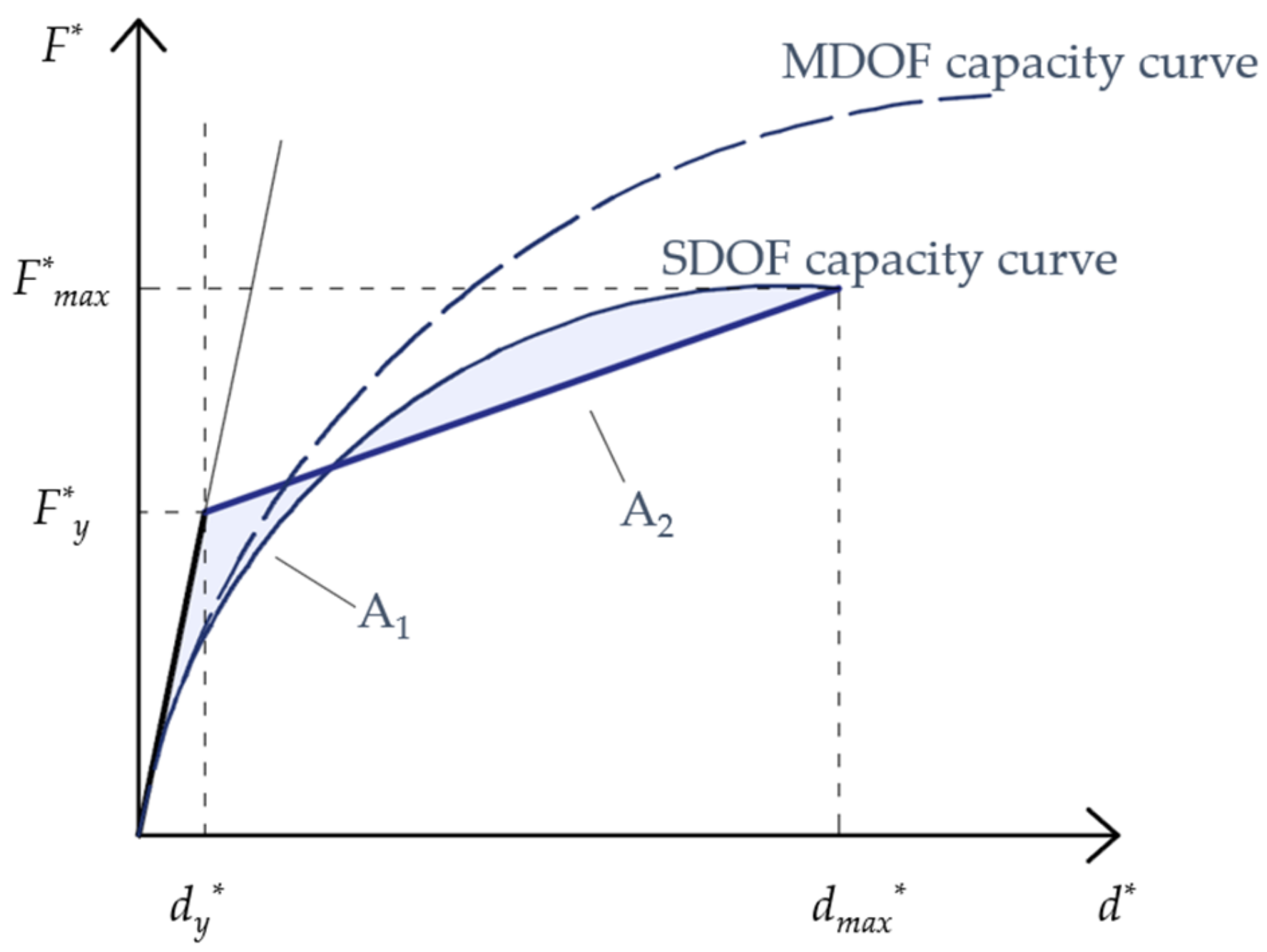
For practical purposes, according to [31], the amount of energy dissipated by the system, and therefore the equivalent viscous damping ratio ξeq, is evaluated by replacing the capacity curve of the equivalent SDOF system by an equivalent bilinear curve, determined based on the principle of energetic equivalence. The performance point (PP) of the system can be determined by applying either Method A, based on the principle of equal displacements or equal energies, or Method B, which is based on the Capacity Spectrum Method. In this study, Method B is considered, and the PP is evaluated through an iterative procedure in the acceleration–displacement response spectrum (ADRS) space. As the first step, the displacement at the PP is set equal to d m a x , correspondent to the target seismic displacement of the analyzed structure, where F m a x is the corresponding force determined on the SDOF capacity curve. The equivalent bilinear curve of the equivalent SDOF system is then obtained by imposing same initial stiffness as the initial stiffness of the SDOF capacity curve and identifying the yield point ( d y ; F y ) through the equivalence of areas A1 and A2, as shown in Figure 2.
Through the equivalent bilinear capacity curve, the equivalent viscous damping ratio ξeq is determined with Equation [C7.3.10] of [31]:
ξ e q = k 63.7 ( F y d m a x F m a x d y ) F m a x d m a x + 5
where parameter k accounts for the actual energy dissipation capacity of the structural system. In principle, k should be calibrated based on experimental data, but when relevant data are missing, it can be taken as 1.0 for structures with high damping capability (characterized by wide and stable hysteresis loops), 0.66 for structures with moderate damping capability (moderate change of the hysteresis loops), and 0.33 for structures with low damping capability (hysteresis loops affected by substantial pinching and decrease in area). Through ξeq, the damping reduction factor η is determined to evaluate the damped demand spectrum according to the equation [3.2.4] of the IBC [30]:
η = 10 / ( 5 + ξ e q ) 0.55
The equivalent bilinear curve and the damped spectrum demand are compared in the ADRS plane; their crossing point is the new PP, and Method B is iteratively applied until the difference between two consecutive PPs is sufficiently small.
According to Equation (5), the minimum value of the damping factor η is 0.55, which corresponds to an equivalent viscous damping ratio ξeq = 28%. In a structure equipped with damped braces, ξeq, and consequently η, depends upon the damping capacity of the dampers. In this regard, it must be emphasized that steel hysteretic dampers available nowadays, such as Buckling Restrained Braces (BRBs), friction and extrusion dampers, are characterized by high damping capacity, with ξeq > 28% [3,4,5,6,32,33,34,35,36]. Therefore, the contribution of such dampers to increase the overall damping ξeq of the combined structural system may be not completely considered in the analyses due to the limitation on η [30].
Non-Linear dynamic, or Time-History, analyses (NLTHAs) are acknowledged, by far, to be the most reliable method for predicting the seismic response of structures. However, they involve the formulation of accurate mathematical models of the real structure, are time consuming and the accuracy of the results depends on the assumptions made on the seismic action. Therefore, for ordinary structures, NLTHAs are usually replaced by simpler and computationally less onerous static analyses. Regarding the representation of the seismic input in NLTHAs, the IBC [30] §3.2.3.6 allows for consideration of either natural or artificial accelerograms. The use of artificial accelerograms was attractive in the past years since it allowed for the generation of spectrum compatible time-series even in those cases where the elastic design spectrum was the only available information [37]. Today, thanks to the growing availability of strong motions databases, the use of real accelerograms recorded during earthquakes is preferred [38]. According to the IBC [30] §3.2.3.6, natural accelerograms must be selected and properly scaled in magnitude in order to match, on average, the target elastic spectrum at a 5% equivalent viscous damping ratio (with lower and upper tolerances of −10% and +30%, respectively) in the range of periods relevant for the specific case study, which is the largest between 0.15 ÷ 2 s and 0.15 ÷ 2 T, where T is the fundamental elastic period of the structure in the direction where the accelerogram is applied. In case artificial accelerograms are used, they are generated to match, on average, the elastic response at 5% viscous damping, with lower tolerance of −10% over the period range. The duration of the accelerograms is consistent with the magnitude and the other relevant features of the seismic event, but when site-specific data are not available, the pseudo-stationary part should be equal to 10 s and the total duration must not be less than 25 s. NLTHAs calculate the actual response of the system over the whole duration of the ground motion time-history and therefore permit to account for the actual dissipation capacity of the hysteretic dampers, overcoming the limitations on the maximum equivalent viscous damping ratio which affect NLSAs in the case of hysteretic dampers with high dissipation capability.
However, in spite of the increasing spread of hysteretic dampers for both new and retrofitted buildings [17,18,19,20,21,22,23,24,25], the IBC [30,31] does not provide specific recommendations for the analyses of structures provided with such devices but refers to the general provisions for buildings in seismic areas. The same consideration is valid also referring to the European design code [39]. In fact, the IBC [30,31] and the European code [39] adopt similar provisions regarding non-linear static and dynamic analyses for structures subjected to seismic actions. This highlights that at the European level, there is also a lack of a clear guidance for practitioners who must tackle the design of damping systems for buildings, including instructions on the type of analyses to be performed. The present study aims at providing some guidance in this regard by comparing the results on NLSAs and NLTHAs of two archetype reinforced concrete (RC) frame buildings retrofitted with hysteretic steel braces in accordance with the requirements of the code [30,31].
A parametric study is performed exploring various design solutions that consider hysteretic dampers with different ductility and stiffness, and two sites, with the goal of assessing the accuracy of NLSAs for buildings retrofitted with energy dissipation systems. To better highlight the limitations of the non-linear static procedure, the analyses are performed either considering limitation η ≥ 0.55 or using the actual η resulting from the equivalent viscous damping ratio of the retrofitted system. Additionally, since according to the code [30,31] either natural or artificial accelerograms can be used in NLTHAs, a secondary goal of the study is to compare the results obtained using either time-histories. It is important to emphasize that within this article, reference is made exclusively to the IBC [30,31]. Nevertheless, given the similarity between the Italian and European codes concerning the non-linear analysis methods, the relevance of this work should not be interpreted as solely limited to the Italian context.

2. RC Case Study Structures

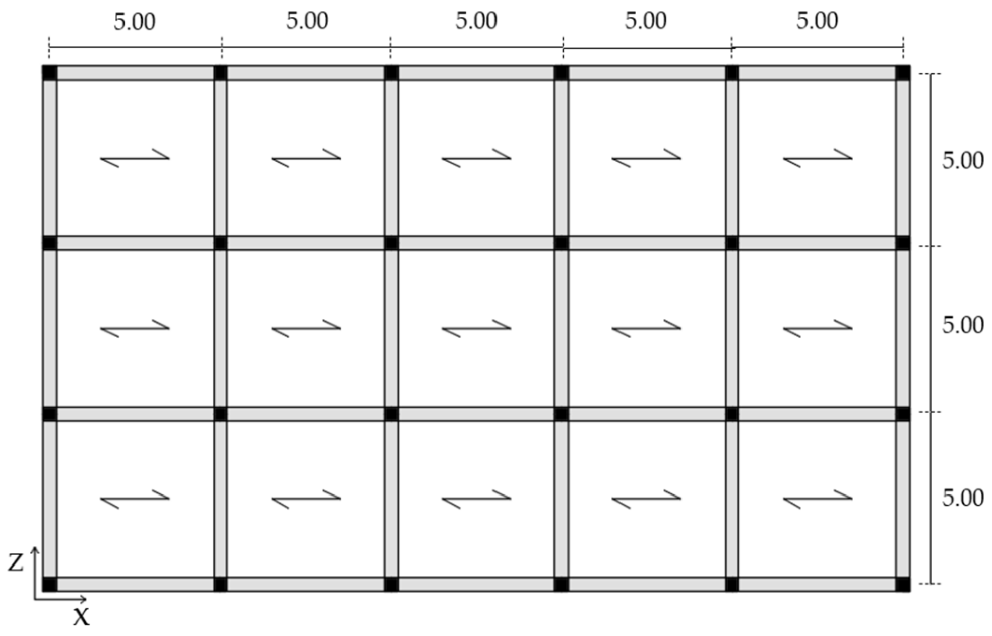
Two archetype buildings characterized by a RC moment-resisting frame taken from the literature [40] are assumed to be case studies. The first is a three-story building, and the second is a six-story building. Both buildings have the same 25 × 15 m2 plan shown in Figure 3 and composed by bays of 5 m in each horizontal direction.
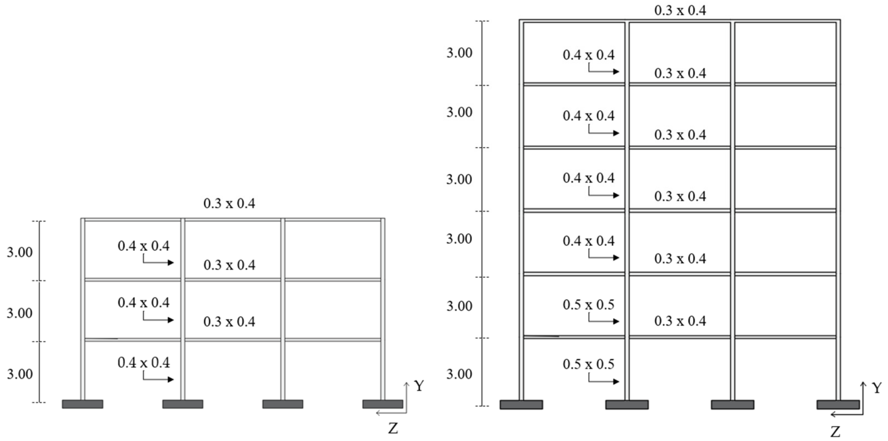
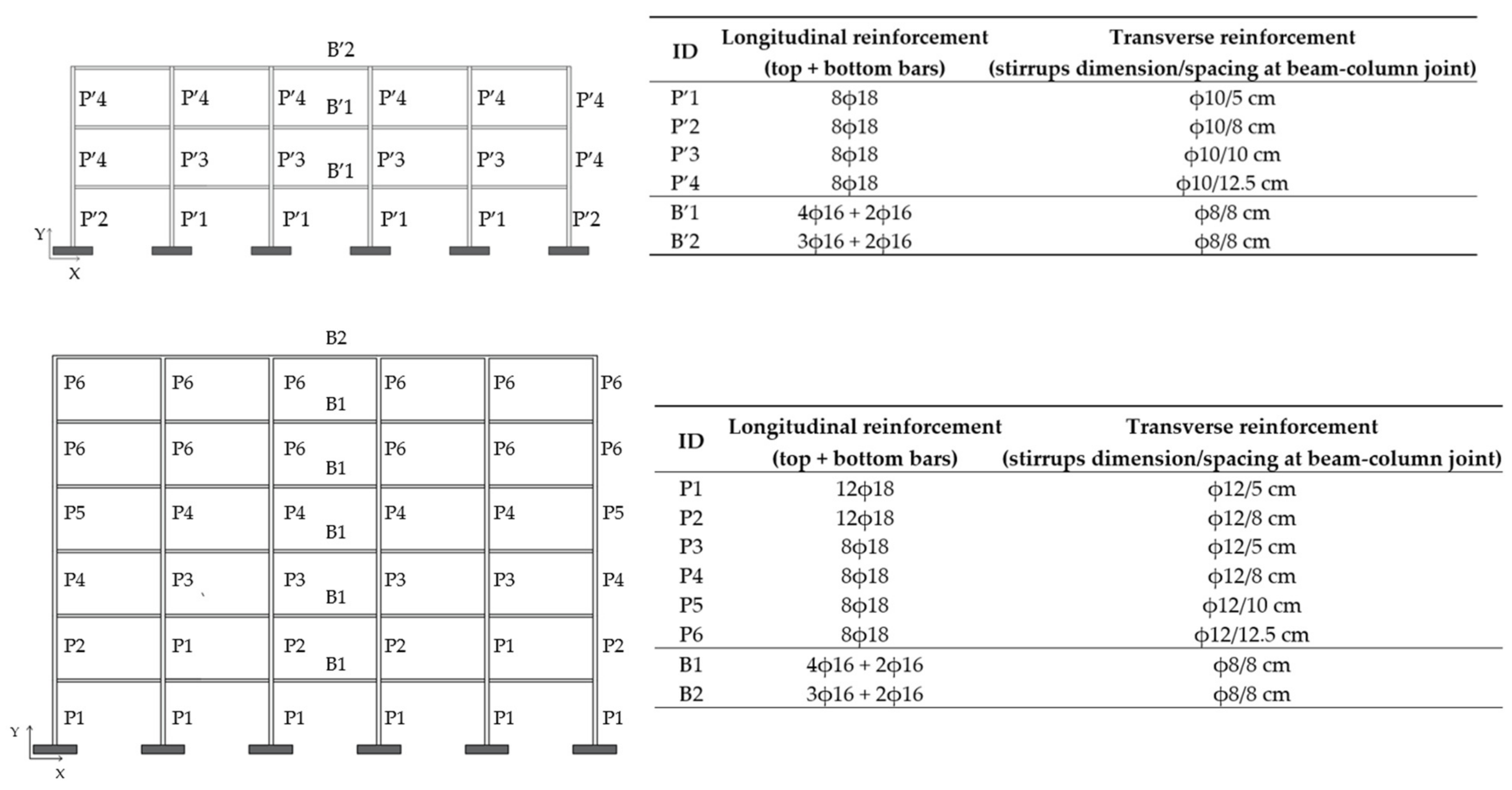
Figure 4 shows the elevation views with indication of the inter-story height and cross-sections of the structural members, while Figure 5 reports the reinforcement of beams and columns.
Both structures are designed following the prescriptions of the IBC [30] for residential building use, considering a moderate seismicity area with a PGA = 1.91 m/s2 and a B soil type. The design is performed for a low ductility class (Class B) assuming C25/30 concrete and B450C steel [30] for reinforcement. Permanent non-structural loads comprise a 20 cm thick reinforced concrete slab supporting a 5 cm screed (0.95 kN/m2), flooring (0.4 kN/m2), and partition walls (1.6 kN/m2) for intermediate stories, while live loads equal to 2 kN/m2 are assumed in accordance with IBC [30] for residential buildings.

3. Design of the Seismic Retrofit

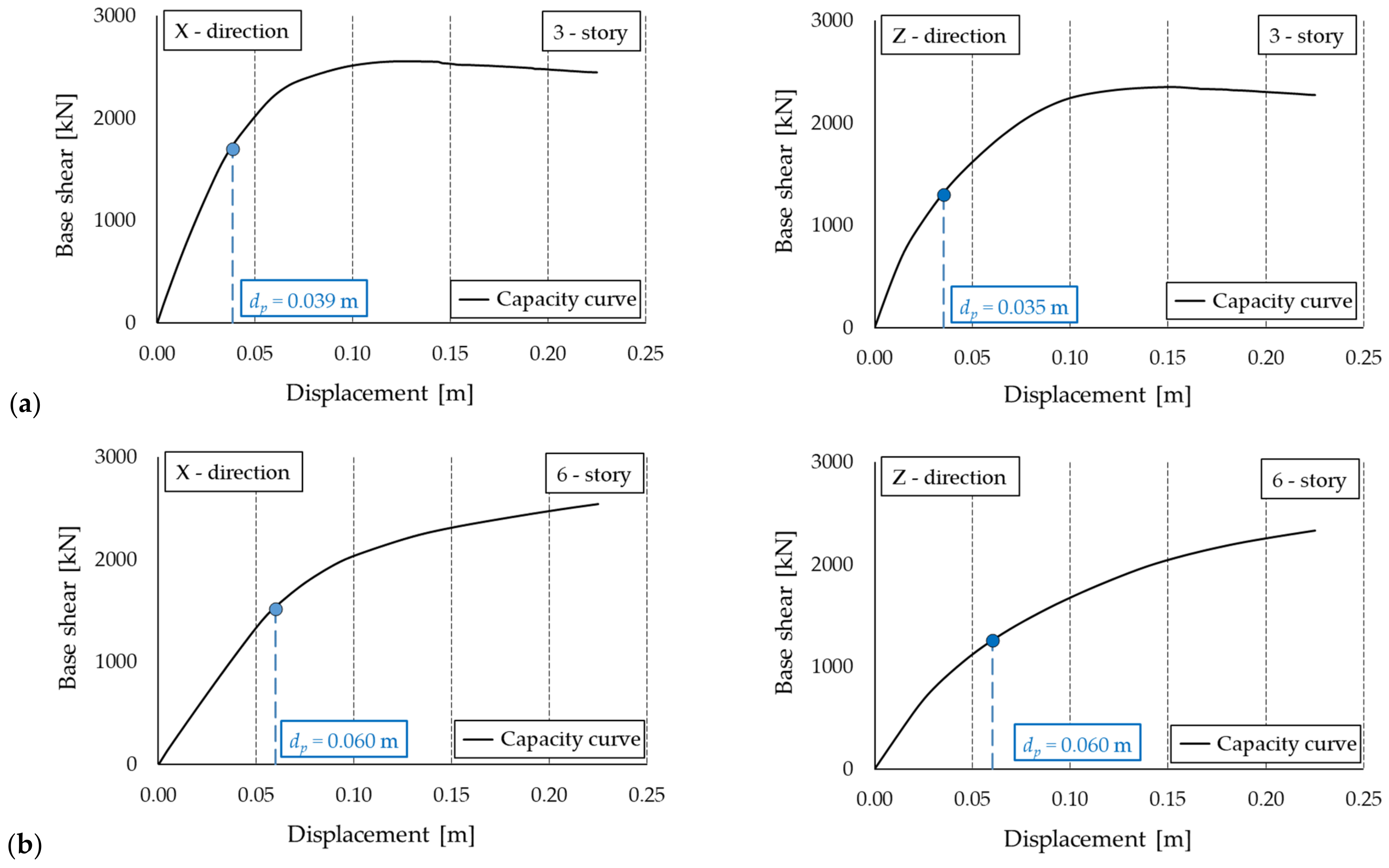
The case study structures are retrofitted in accordance with the IBC [30] referring to the seismic loads for Life safety limit state (LLS) related to the municipalities of Benevento (Long 14.787°, Lat 41.1305°) and Tramutola (Long 15.7919°, Lat 40.3176°), which are two sites of high seismicity in southern Italy. The design is performed assuming a typical residential building use with nominal life VN = 50 years and functional class cu = II. A T1 topography, and soil type B is considered for Benevento resulting in a PGA equal to 2.94 m/s2, while T1 topography and soil type C are assumed for Tramutola for a PGA = 3.41 m/s2. The retrofit design is carried out applying a procedure developed by the authors of work [1,41]. This methodology is implemented in the ADRS space, where the structural system composed of the RC frame and the hysteretic dampers is modelled through an equivalent SDOF system, characterized by its secant stiffness and equivalent viscous damping ratio. It is important to recall that a pre-requisite for this procedure is that the behavior of the building is governed by the first mode, legitimating the condensation of the MDOF structure to the equivalent SDOF system. Therefore, this methodology is valid for low-rise and medium-rise buildings, regular in plan and in elevation, as the case studies analyzed in the present work. The sizing of the dampers is carried out in order to reach a desired structural performance level, which is expressed in terms of target displacement dp, evaluated at the top of the structure. In the present study, dp is selected with the aim of guaranteeing the Immediate Occupancy performance level [42] by keeping the main frame in the elastic range or by conceiving at most a controlled concrete cracking, limiting structural damage as much as possible. Therefore, the structures are immediately accessible after a main earthquake correspondent to the LLS according to the IBC [30], characterized by return period TR of 475 years, with a probability of non-exceedance of 10% for nominal life VN = 50 years of a residential building (cu = II). Figure 6 shows the capacity curves of the case study buildings and the relative dps which correspond to the ending point of the elastic branch, or at most at the beginning of the second branch relevant to the cracked concrete [43].
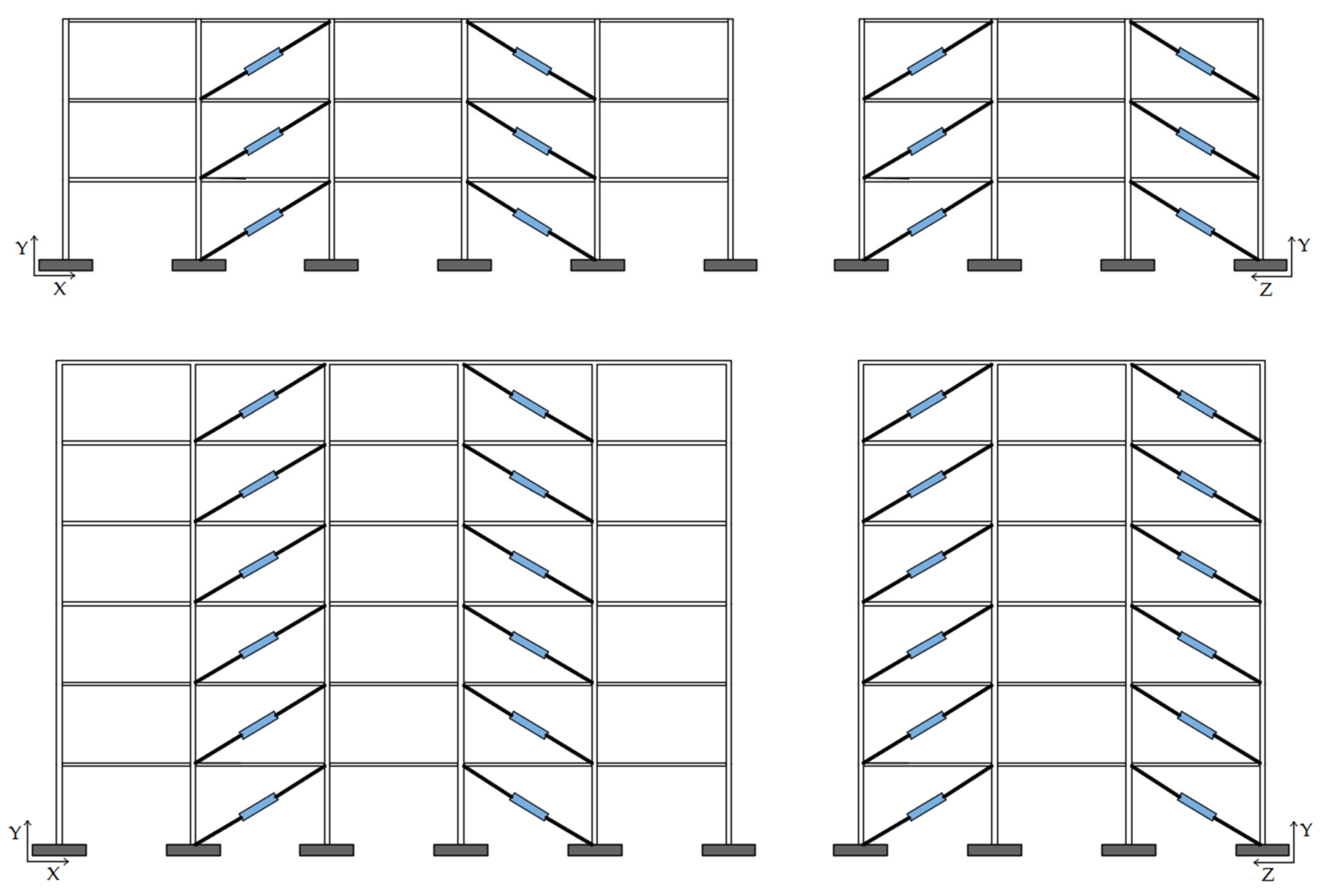
In this study, the two structures are retrofitted by using hysteretic steel dampers installed into diagonal steel braces (Figure 7), which is a common configuration for frame buildings [1,5,6,43,44,45]. An elastic–perfectly plastic constitutive behavior is assumed for the dampers, similarly to other studies [1,6,41,43,44]. Four units on each floor in both X and Z directions are installed in the external bays according to the layout shown in Figure 7.
The mechanical properties of each diagonal steel brace and the encased hysteretic steel damper form an in-series system can be expressed as a combination of the properties of the linear elastic brace (B) and of the elasto-plastic damper (D), as shown in Figure 8, where KB and KD are the elastic stiffnesses of the brace and of the damper, Vy is the maximum force of the damper, dy, dbd and d2 are the yield displacement, the design seismic displacement calculated at LLS and the ultimate displacement of the damper at CLS, respectively. Damper ductility μD, defined as the ratio between dbd and yield deflection dy, for standard steel hysteretic dampers typically ranges between 4 and 16 [1,15,41,43]. The properties of the single damped brace (DB), in terms of stiffness KDB, ductility μDB, and damping capacity ξDB, are determined through the Equations (6)–(8), where ratio KB/KD between the stiffnesses of the steel brace and the damper should be taken ≥2 in order to guarantee that the largest part of the deformation of the story is concentrated in the damper [45,46]. Typical values of μDB and ξDB for damped bracing systems according to current practice are reported in Table 1 [15,43,44]. Therefore, in the study, the seismic upgrade of the case study buildings is performed considering damped brace systems characterized by values of ductility μDB ranging from 3 to 13.5; more specifically, μDBs equal to 3, 5, 7, 9, 11, and 13.5 are assumed.
K D B = K D K B K D + K B
μ D B = 1 + μ D 1 1 + K D K B
ξ D B = 2 π · μ D B 1 μ D B

4. OpenSees Numerical Model

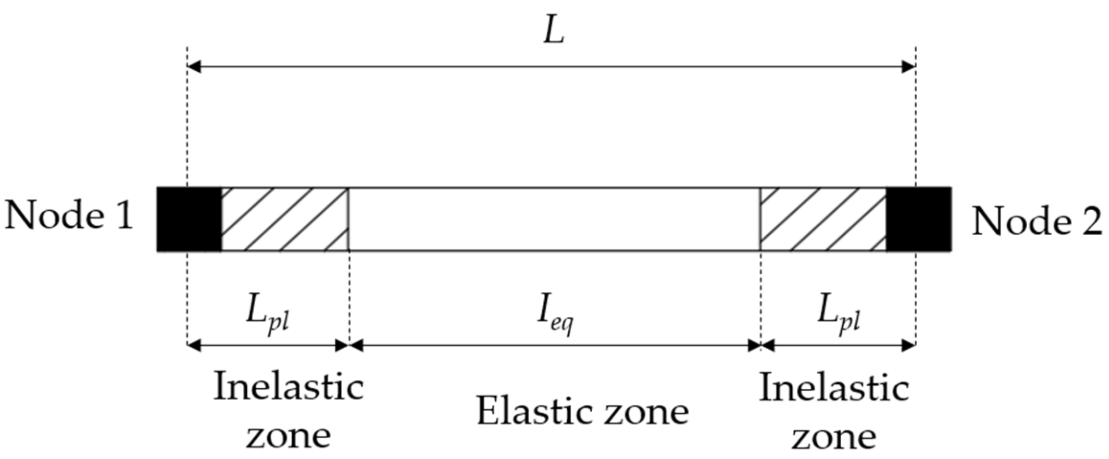
The case study structures are modelled as 3D buildings in the OpenSees software program version 3.6.0 [47,48], adopting the modelling procedure presented in [49] and validated in [1,5,6,41,43]. Beams and columns are implemented through the forceBeamColumn element object [50], assigning a non-linear behavior to the external sections and a linear elastic behavior to the internal section of the element, as shown in Figure 9. Since the case study structures are designed to fail in flexure in accordance with the requirements of the IBC [30], the external sub-elements correspond to the dissipative areas in which plastic flexural mechanisms are expected to be activated and concrete is defined with a well-detailed confinement model, correspondent to the Concrete04 material model, which is based on the model proposed by Popovics [51]. In particular, concrete is assumed nonresistant under tension, and the core region is characterized by concrete strength fcc and deformations εcc and εcu defined according to Equations (A.6)–(A.8) of Part 3 of Eurocode 8 [52]. The length of dissipative zones Lpl (plastic hinge length) is defined according to Equation (A.9) of Eurocode 8 [52]. Regarding the reinforcement, the single steel bar is modelled as a fiber defined through the material model Steel02 with isotropic strain hardening [53,54], assuming a strain-hardening ratio b equal to 0.005 [40] and the parameters that control the transition from the elastic to the plastic branch as R0 = 18, CR1 = 0.925, CR2 = 0.15. An effective area moment of inertia, Ieq = 0.5Ig, where Ig is the area moment of inertia of the gross section, is assigned to the internal elastic section to account for concrete cracking.
The floor slabs are defined as rigid diaphragms where the masses of the structural members are concentrated in the center of mass of each story. Since the rigid diaphragms constrains the nodes belonging to the same floor to have the same displacement, a fictitious axial force is generated in the beams, as demonstrated in [55]. Therefore, it is necessary to add an axial release in the form of an axial buffer (defined through a zeroLength element object [56]) between one end of each beam and the adjacent node.
Dead and live loads are calculated according to the tributary area concept and introduced in the model as uniformly distributed loads on the beams. The analyses consider the P-Delta effects, while they disregard bond slip and low-cycle fatigue effects. The columns are designed to be rigidly connected to the ground; thus, fixed base supports are defined in the model. The Rayleigh method defined as a function of the tangent stiffness matrix with a 5% viscous damping ratio is used to consider the damping of the frame, as reported in Ref. [40].
The diagonal steel braces equipped with the hysteretic dampers are modelled by means of a truss element object [48] with an assigned uniaxialMaterial elastic–perfectly plastic behavior, as commonly implemented in other studies (e.g., [43,44,57,58,59]).

5. Selection of the Accelerograms for the Non-Linear Time-History Analyses

The NLTHAs are conducted in accordance with the provisions of the IBC [30] referring to the seismic action in the municipalities of Benevento (soil type B and T1 category) and Tramutola (soil type C and T1 category). Two limit states characterized from different return periods of the design earthquake are considered, namely (i) the Life safety Limit State (LLS) with return period TR = 475 years and (ii) the Collapse Limit State (CLS) with return period TR = 975 years. Figure 10 shows the ξ = 5% damped spectra with indication of the PGAs at either site for the two limit states and the fundamental period of each building.
Following the prescriptions at §3.2.3.6 of the IBC [30], a suite of seven independent accelerograms is needed to perform NLTHAs. In the study, for each site and limit state, two sets of bidirectional accelerograms, both artificial and natural, were considered. Seven pairs of artificial accelerograms with a pseudo-stationary part of 10 s and a total duration of 30 s were generated using SIMQKE software program version 2.7 [60]. Seven pairs of natural ground motions were selected from the European Ground Motion Database [61] using REXEL software program version 3.5 [62]; the natural accelerograms are characterized by a magnitude (Mw) within the interval of [5,6,7] and an epicentral distance (Rep) in the range of 0–30 km. The selected accelerograms are compatible with the elastic design spectrum from the IBC [30] with 5% equivalent viscous damping ratio for an ordinary structure with cu = II and VN = 50 years.
With the aim of obtaining results independent from the directionality of the excitations, two analyses were carried out for each bidirectional ground motion by switching the two components of the seismic input with respect to the main plan directions (X and Z) of the building.

6. Results of Non-Linear Analyses

The results of the non-linear analyses are evaluated in terms of maximum displacement at the roof level (d), selected as control point, maximum inter-story drift ratio (Δ), and maximum shear force at the base (V), which are engineering demand parameters (EDPs) usually considered to investigate the performance of the structural system and the effectiveness of the retrofit design [1,5,6,15,17,18,41,43,44].
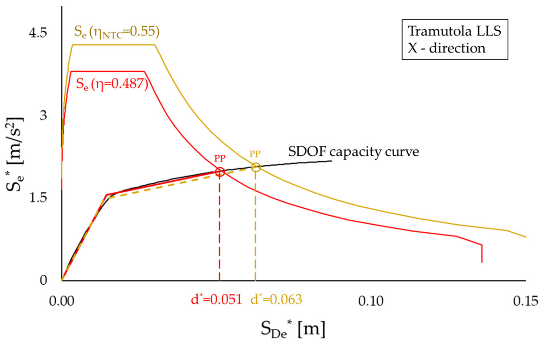
As an example, Figure 11 shows the results at LLS for the six-story building in Tramutola retrofitted with damped braces with ductility μDB = 9. The damped spectrum depicted in red corresponds to the damping reduction factor η resulting from the actual ξ e q evaluated as 10 / ( 5 + ξ e q ) which in this case amounts to 0.487. The yellow curve refers to the case in which the damping reduction factor is evaluated in accordance with the IBC [30] as η I B C = m a x ( 0.55 ; 10 / ( 5 + ξ e q ) ) . The actual η results in a −22.4% in the displacement at roof level and −4.1% in the global shear force in comparison to the values calculated by assuming ηIBC.
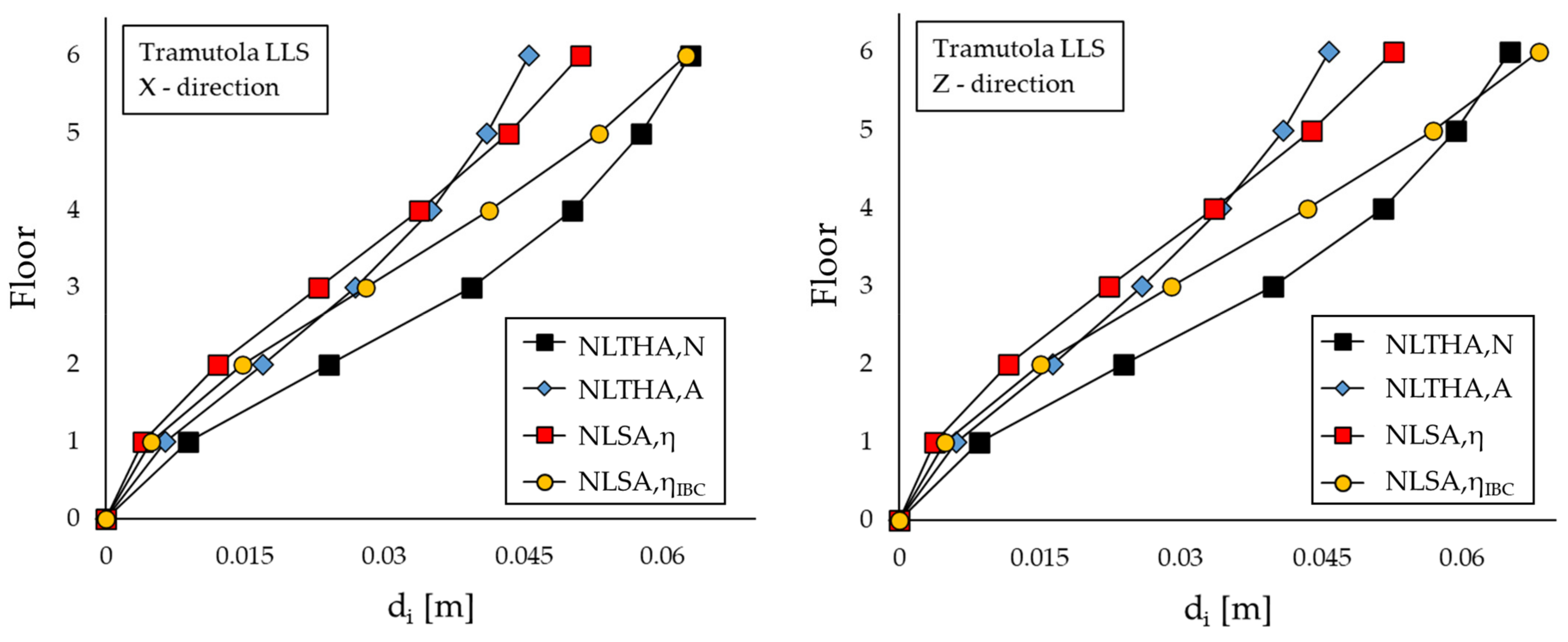
For the same case study structure, Figure 12 shows the comparison between the maximum displacements at each floor obtained from static and dynamic non-linear analyses in X and Z directions. In the graph, NLTHA,N and NLTHA,A stand for Non-Linear Time-History analyses with either natural (N) or artificial (A) accelerograms, while NLSA,η and NLSA,ηIBC refer to non-linear static analyses considering either η or ηIBC, respectively. NLTHA,N calculates the largest displacements at each floor, but the last one where its results are similar (or even smaller than) to NLSA,ηIBC. For the first three floors, NLTHA,A, NLSA,η, and NLSA,ηIBC provide consistent results, smaller than those calculated from NLTHA,N, but their estimates diverge at the upper floors. Regarding the displacement of the control point, curiously, in the X direction, the maximum and minimum values are calculated by the two time-history analyses, with a deviation of about 27% in the X direction and 29% in the Z direction; in the Z direction, the largest displacement is calculated by NLSA,ηIBC. There is a deviation of approximately 19% in both directions between NLSA,η and NLTHA,N, while NLSA,ηIBC yields results quite similar to those of NLTHA,N, with a difference of about 5% at the top floor in the Z direction.
For each analysis, results similar to those shown in Figure 12 are obtained for displacements, inter-story drift ratio and shear forces in the columns at the base floors. Hereinafter, the results of the non-linear analyses are compared to the values obtained from NLTHAs with natural accelerograms, assumed as benchmark by means of some simple indexes. Specifically, the three dimensionless ratios, d/dTH,N, Δ/ΔTH,N, and V/VTH,N are introduced. In these ratios, d, Δ and V represent the maximum displacement at the roof level, the maximum inter-story drift ratio, and the maximum shear force at the base, respectively. Each response parameter (d, Δ and V) is calculated in a non-linear analysis (NLSA with actual η, NLSA with ηIBC, and NLTHA,A) and then compared to the corresponding quantity determined from the NLTHAs with natural accelerograms (dTH,N, ΔTH,N and VTH,N, respectively).
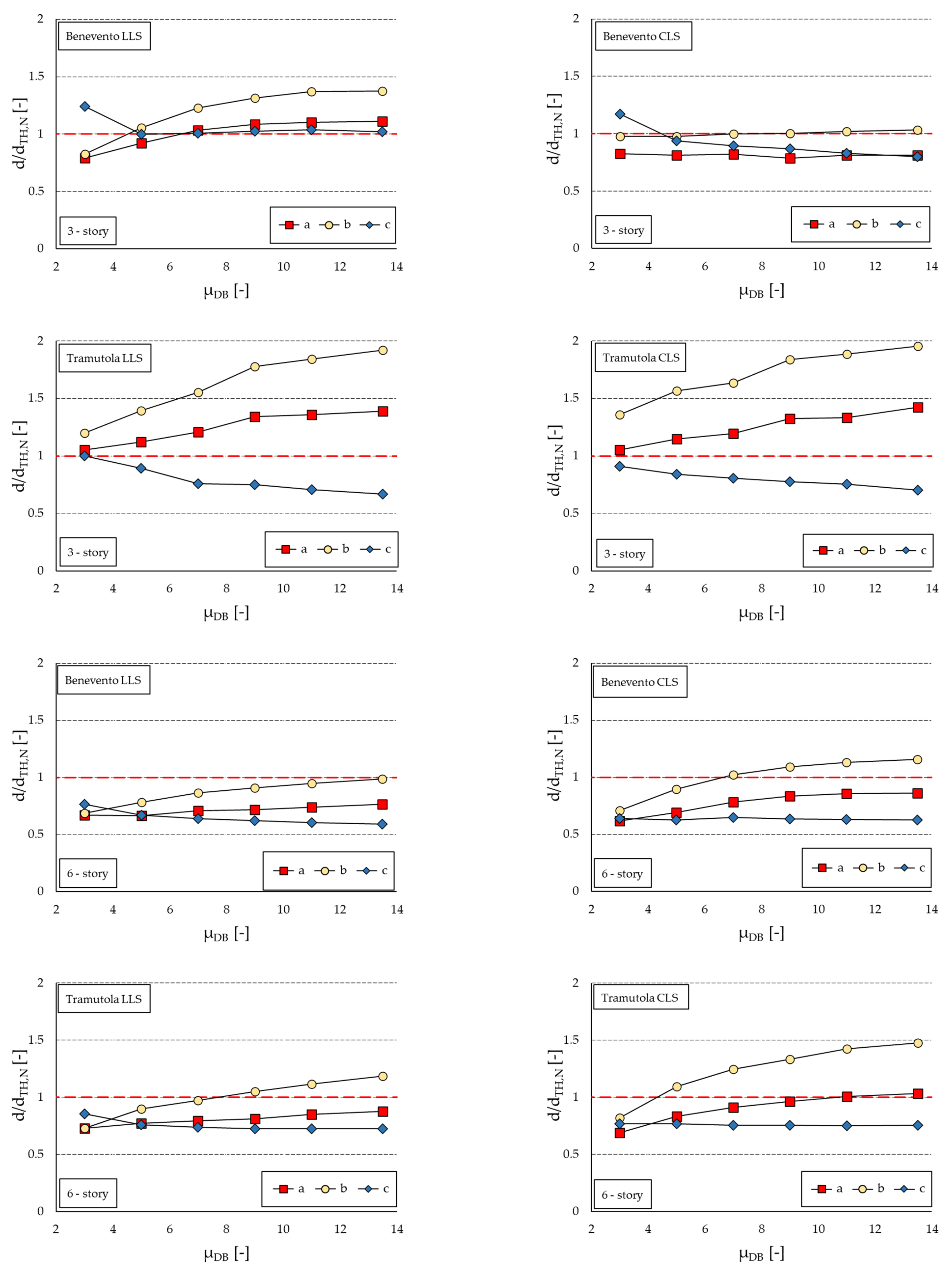
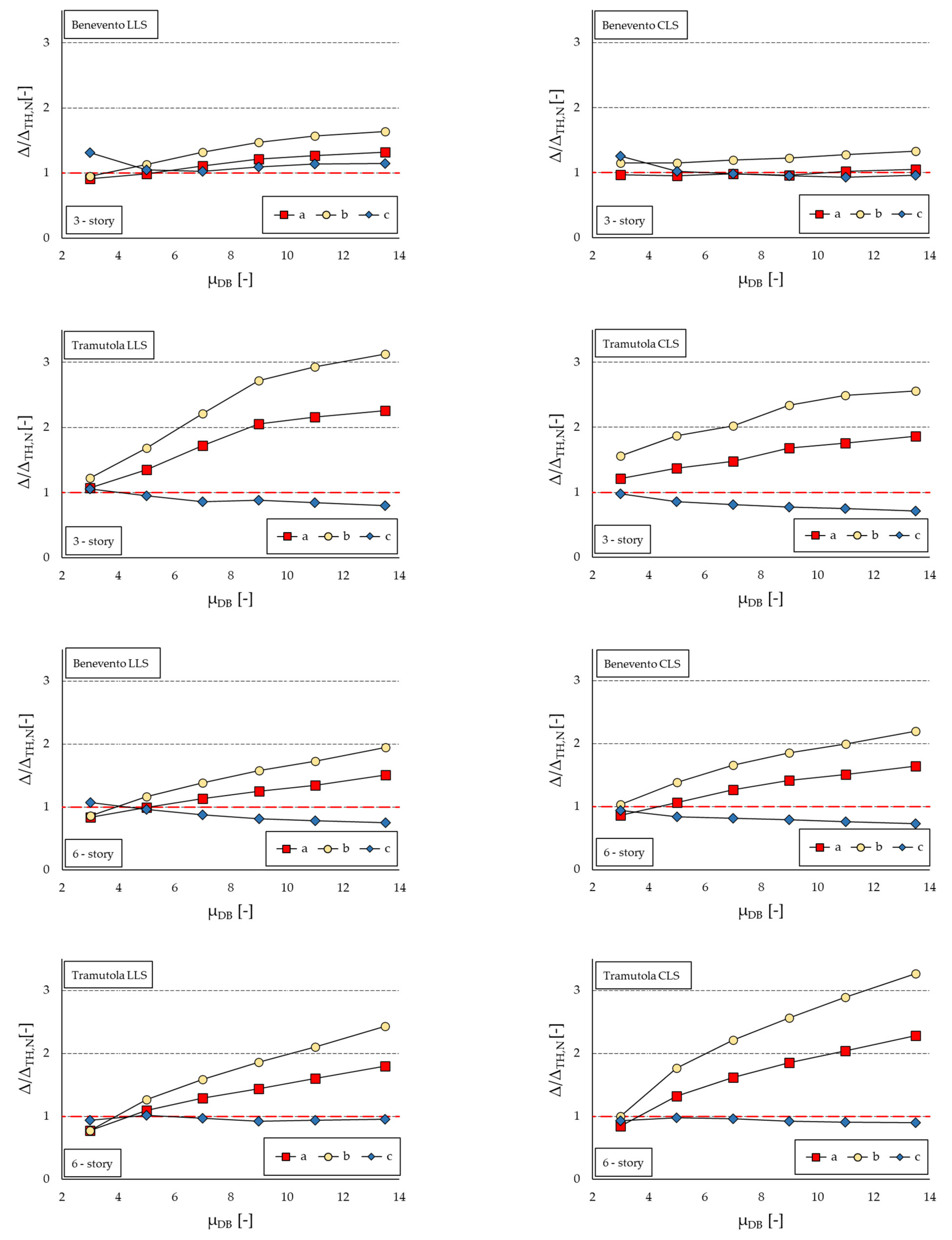
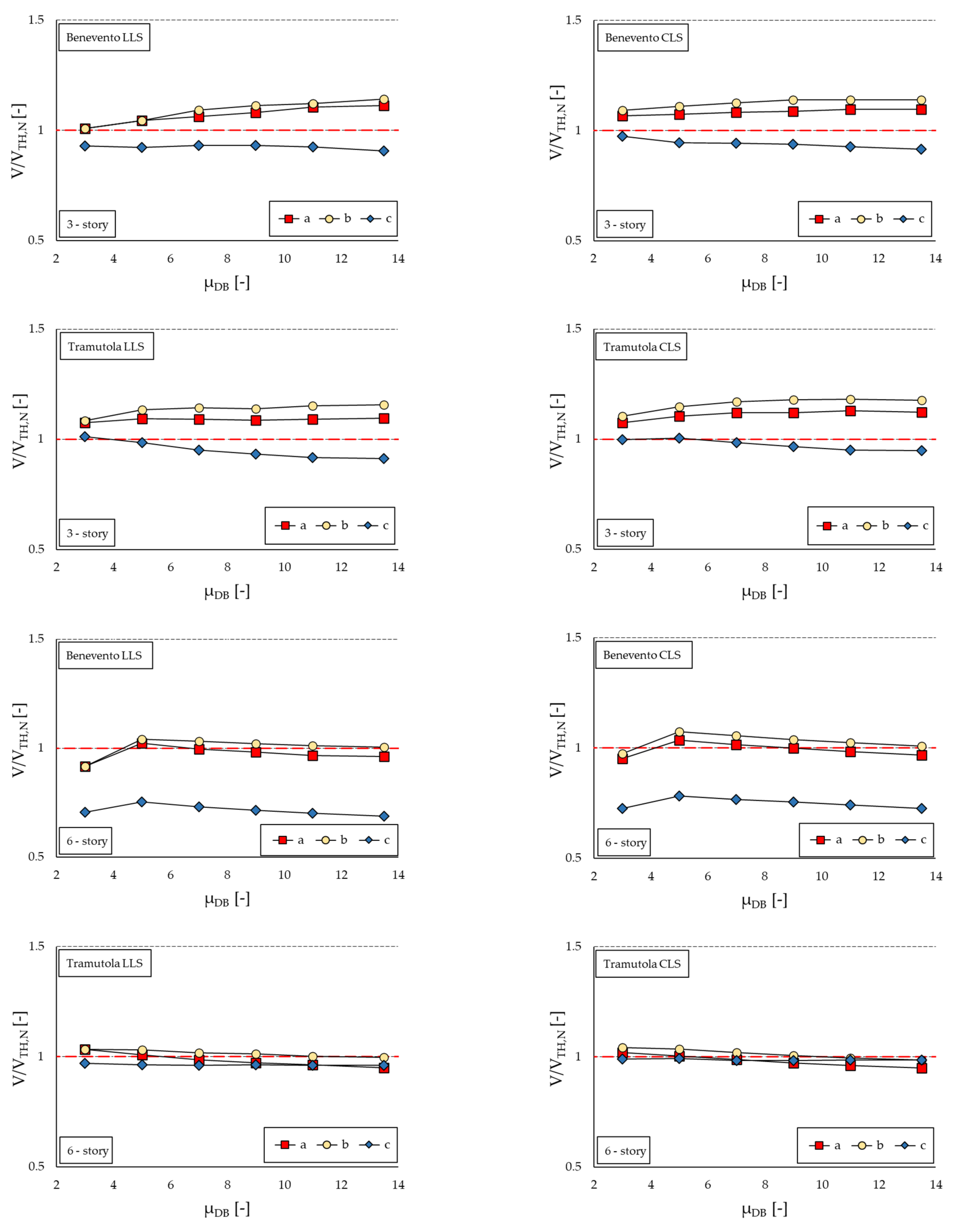
Figure 13, Figure 14 and Figure 15 show the dimensionless ratios for the two buildings associated to the examined μDBs (for each index, the largest between the values for the X and Z directions is reported). The curves are labelled as follows: curve (a) shows the results from NLSAs where the actual damping reduction factor η = 10 / ( 5 + ξ e q ) is considered; curve (b) reports the results from NLSAs in which η I B C = m a x ( 0.55 ; 10 / ( 5 + ξ e q ) ) is used; curve (c) shows the results from NLTHAs with artificial accelerograms.
The deviation on the top building displacement is examined in Figure 13. For the three-story building, NLSAs overestimate the top building displacement calculated by NLTHA,N except for Benevento (CLS) where d/dTH,N is approximately equal to unity for NLSA,ηIBC, and about 0.8 for NLSA,η. Also, in the case of Benevento (LLS), for μDB = 3, NLSA,ηIBC underestimates the results from NLTHA,N. Considering the site of Tramutola, for both limit states, d/dTH,N ranges from 1.05 to 1.40 for NLSA,η and from 1.20 to about 2.0 for NLSA,ηIBC.
The opposite trend is revealed for the six-story building: NLSA,η underestimates the benchmark displacement for both sites; d/dTH,N is approximately constant at LLS, while it tends to increase with μDB at CLS and approaches unity for the case of Tramutola when μDB ≥ 9. In general, NLSA,ηIBC yields conservative results at CLS when μDB ≥ 5 (Tramutola) or μDB ≥ 7 (Benevento), while at LLS it underestimates the displacement of the top floor for small μDB.
NLTHA,A always estimates lower values than NLSAs. More specifically, when referring to d/dTH,N (Figure 13), NLTHA,A underestimates the top displacement calculated from NLTHA,N in either building. Only in the particular case of the three-story building in Benevento do artificial accelerograms provide larger (for μDB = 3) or similar displacements than natural ones. As a general trend, for the three-story building, ratio d/dTH,N decreases as μDB increases, while for the six-story building the ratio is virtually independent of the properties of the damped brace system, at least when μDB ≥ 5. Additionally, for the six-story building at both sites, similar values of d/dTH,N are obtained at LLS and CLS, showing that the accuracy is little affected by the intensity of the earthquake. Disregarding the case of μDB = 3, for the three-story building, the maximum deviation from the benchmark is about −20% in Benevento and −22% in Tramutola, while for the six-story buildings the corresponding figures are −28% and −25%, respectively. It is worth noticing that for the three-story building in Benevento, NLTHA,A and NLSA,η provide results remarkably close to each other, and this similarity increases with the increase in the ductility of the damping system.
By looking at Figure 14 relevant to Δ/ΔTH,N, non-linear static analyses provide rough estimates of the maximum inter-story drift, with overestimates that increase almost proportionally with μDB, with the only exception of Benevento CLS where Δ/ΔTH,N is close to unity. Notably, for low damper ductility (μDB = 3), Δ/ΔTH,N is always close to one. The ratio between inter-story drifts calculated by NLSA,η and by NLSA,ηIBC is as large as 1.3 (Benevento)/1.6 (Tramutola) for the three-story building, and 2.0 (both Benevento and Tramutola) for the six-story building. Again, NLTHA,A provides better estimates, with maximum deviations of about 25% to 30% (three-story building in Tramutola and six-story building in Benevento). It is noteworthy that for both buildings equipped with the retrofitting system with μDB = 3 in the sites of Tramutola (at both LLS and CLS) and Benevento (at LLS), all analyses yield consistent results.
In terms of maximum shear force at base V (Figure 15), NLSA,η and NLSA,ηIBC show a fair performance, with V/VTH,N ratios approaching unity: the maximum relative deviations from the benchmark are of the order of +10% (NLSA,η)/+15% (NLSA,ηIBC) for the three-story building and −5% (NLSA,η)/0% (NLSA,ηIBC) for the six-story building. The influences of the seismic scenario and of the ductility of the damping system are negligible. On the other hand, NLTHA,A underestimates the shear force by 10% for the three-story building (Benevento and Tramutola), by 25–30% for the six-story building in Benevento and by less than 5% for the six-story building in Tramutola. Also, for NLTHA,A, virtually no influence of μDB is shown.
The main trends highlighted from the results shown in Figure 13, Figure 14 and Figure 15 are summarized as follows:
  • NLSAs provided accurate estimates of forces for both buildings (maximum deviation +15% in the study), and the accuracy was virtually unaffected by the ductility of the dampers.
  • NLSAs are not accurate when the structural performance is evaluated referring to displacements and deformations, e.g., maximum displacements between adjacent buildings or inter-story drifts. Only for low values (μDB = 3) and in some cases even medium–low values (μDB = 5) of ductility of the dissipative bracing system the estimates provided by NLSAs are fair, while the accuracy deteriorates as the damping capacity of the bracing systems increases. These estimates are always on the conservative side, but there is a potential concern of ending up with a design that is overly conservative.
  • Focusing on the outcomes in terms of maximum displacements at the top floor, the study is unable to provide conclusive results, as deviations from the benchmark range from −30% to +200% depending on the building type, seismic scenario, and characteristics of the dissipative bracing system. However, as previously highlighted, the general trend shows that the accuracy of results deteriorates as μDB increases. Moreover, in the six-story building, NLSAs with η I B C = max ( 0.55 ; 10 / ( 5 + ξ e q ) ) underestimate the displacement for low μDBs (≤5) and overestimate it for high μDBs.
  • NLTHA,N generally underestimate the demand values in terms of forces and displacements, often by up to 30%. This underestimation occasionally shows a modest reduction with increasing μDBs. In some cases, e.g., for μDB = 3, there is even an overestimation of the maximum displacement and maximum inter-story drift. It is important to emphasize that in this study, the results of NLTHA,N are referred to as benchmark. However, both NLTHA,N and NLTHA,A are considered equivalent according to the IBC [30].
The study has some limitations, and its findings should not be considered as general until confirmed by further data. Firstly, the study focused only on two RC frames representative of low- to medium-rise structures with regular floor in plans and elevations; therefore, these results are representative of these categories of buildings. However, it is important to emphasize that in Italy, a significant percentage of existing structures consists of low- to medium-rise buildings, such as residential and industrial structures, school buildings, etc. [63], which therefore are covered by the case studies. In particular, almost 70% of the existing residential buildings located in high- and medium-seismicity zones are characterized by a number of stories between one and four [63]. As a second limitation, the study only considered two design scenarios, represented by two design spectra. From the point of view of earthquake engineering, it is evident that the structural dynamic response is significantly influenced also by the dynamic characteristics of the earthquake [64,65]. Therefore, the results of the study need to be confirmed by further analyses considering different sites characterized by diverse topographies and soil conditions to generate a wider set of seismic scenarios. Nonetheless, it is believed that the trends highlighted in the study are of a general nature and therefore can be a valid starting point for a discussion on the reliability of the non-linear analysis methods proposed by the code.

7. Conclusions

This paper aims at assessing the accuracy of NLSAs for analyses of RC buildings retrofitted with hysteretic dampers by means of a parametric study conducted on two regular buildings of either three or six stories. As a matter of fact, no dedicated guidance exists either in the Italian Building Code or in the European code for practitioners who must tackle the design of damping systems for enhancing the seismic performance of buildings, including any instruction on the type of analyses to be performed. The study intends to delve deeper into this gap by providing a first insight into the topic. To this end, engineering demand parameters such as maximum horizontal displacement on the top of the building, maximum inter-story drift ratio, and maximum base shear are calculated and compared to the values predicted by NLTHAs with natural accelerograms. Eventually, the study is extended to NLTHAs using artificial accelerograms.
The main results of the study are summarized in the next points:
  • When referring to the calculation of the total base shear forces, NLSAs can provide acceptable results at significantly lower computational cost compared to NLTHAs. Therefore, they can be suitable when the effectiveness of the retrofit design is evaluated comparing internal actions with capacities; the accuracy of the analyses seems to be not substantially affected by the mechanical characteristics of dissipative braces;
  • NLSAs provide fair predictions of inter-story drift only for dampers with low or moderate–low ductility (e.g., μDB ≤ 5); the accuracy quickly deteriorates as μDB increases, and the error can be higher than 100% when μDB ≥ 10. Even in case, in derogation to the code, a damping reduction factor η < 0.55 is considered, the deviation can be unacceptable, leading to an extremely overconservative design;
  • The study was unconclusive regarding the accuracy of NLSAs in predicting absolute displacements, even if it suggests that the analyses underestimate the displacement for small μDBs and overestimate for high μDBs;
  • Results of NLTHAs are significantly affected by the set of accelerograms used, either artificial or natural, with absolute deviations on the order of up to 30%; the consistency between the analyses depends on the characteristics of the building and of the examined seismic scenario.
Though the results are restricted to two regular RC buildings and two seismic scenarios, the study has the merit, according to the authors’ opinion, of highlighting some limitations of non-linear static analyses for RC buildings retrofitted with hysteretic dampers, pointing out the conditions where a fair accuracy can be expected and when not.
It is therefore hoped that the next code revision will introduce practical recommendations for carrying out seismic analyzes of structures retrofitted with dissipative bracing, specifying the limits of applicability of the various methods. Furthermore, the code should also clarify the methods for performing non-linear dynamic analyses, recommending the accelerograms to be used. As shown in the study, sets of artificial and natural accelerograms, considered equivalent at a regulatory level, can produce significantly different results.

Author Contributions

Conceptualization, E.B. and V.Q.; methodology, E.B. and V.Q.; software, E.B.; investigation, E.B.; data curation, E.B.; writing—original draft preparation, E.B.; writing—review and editing, V.Q.; visualization, E.B.; supervision, V.Q. All authors have read and agreed to the published version of the manuscript.

Funding

This research has been developed within the MUSA—Multilayered Urban Sustainability Action—project, funded by the European Union—NextGenerationEU under the National Recovery and Resilience Plan (NRRP) Mission 4 Component 2 Investment Line 1.5: Strengthening of research structures and creation of R&D “innovation ecosystems”, setup of “territorial leaders in R&D”.

Data Availability Statement

The datasets presented in this article are not publicly available because generated within the MUSA—Multilayered Urban Sustainability Action—project. Requests to access the datasets should be directed to the authors.

Conflicts of Interest

The authors declare no conflicts of interest.

References

  1. Bruschi, E.; Quaglini, V.; Calvi, P.M. A Simplified Design Procedure for Seismic Upgrade of Frame Structures Equipped with Hysteretic Dampers. Eng. Struct. 2022, 251, 113504. [Google Scholar] [CrossRef]
  2. Zoccolini, L.; Bruschi, E.; Cattaneo, S.; Quaglini, V. Current Trends in Fluid Viscous Dampers with Semi-Active and Adaptive Behavior. Appl. Sci. 2023, 13, 10358. [Google Scholar] [CrossRef]
  3. Quaglini, V.; Pettorruso, C.; Bruschi, E. Experimental and Numerical Assessment of Prestressed Lead Extrusion Dampers. Ing. Sismica 2021, 38, 46–68. [Google Scholar]
  4. Quaglini, V.; Pettorruso, C.; Bruschi, E. Design and Experimental Assessment of a Prestressed Lead Damper with Straight Shaft for Seismic Protection of Structures. Geosciences 2022, 12, 182. [Google Scholar] [CrossRef]
  5. Bruschi, E.; Zoccolini, L.; Cattaneo, S.; Quaglini, V. Experimental Characterization, Modeling, and Numerical Evaluation of a Novel Friction Damper for the Seismic Upgrade of Existing Buildings. Materials 2023, 16, 1933. [Google Scholar] [CrossRef] [PubMed]
  6. Bruschi, E.; Quaglini, V. Assessment of a Novel Hysteretic Friction Damper for the Seismic Retrofit of Reinforced Concrete Frame Structures. Structures 2022, 46, 793–811. [Google Scholar] [CrossRef]
  7. Terenzi, G. Novel Design Procedure for Steel Hysteretic Dampers in Seismic Retrofit of Frame Structures. Eng. Struct. 2023, 284, 115969. [Google Scholar] [CrossRef]
  8. Dolce, M.; Cardone, D.; Marnetto, R. Implementation and Testing of Passive Control Devices Based on Shape Memory Alloys. Earthq. Eng. Struct. Dyn. 2000, 29, 945–968. [Google Scholar] [CrossRef]
  9. Nabid, N.; Hajirasouliha, I.; Escolano Margarit, D.; Petkovski, M. Optimum Energy Based Seismic Design of Friction Dampers in RC Structures. Structures 2020, 27, 2550–2562. [Google Scholar] [CrossRef]
  10. Ferraioli, M.; Lavino, A. A Displacement-Based Design Method for Seismic Retrofit of RC Buildings Using Dissipative Braces. Math. Probl. Eng. 2018, 2018, 5364564. [Google Scholar] [CrossRef]
  11. Lavan, O.; Dargush, G.F. Multi-Objective Evolutionary Seismic Design with Passive Energy Dissipation Systems. J. Earthq. Eng. 2009, 13, 758–790. [Google Scholar] [CrossRef]
  12. Palermo, M.; Silvestri, S.; Gasparini, G.; Trombetti, T. Crescent Shaped Braces for the Seismic Design of Building Structures. Mater. Struct. 2015, 48, 1485–1502. [Google Scholar] [CrossRef]
  13. Segovia, V.A.; Ruiz, S.E. Direct Displacement-Based Design for Buildings with Hysteretic Dampers, Using Best Combinations of Stiffness and Strength Ratios. J. Earthq. Eng. 2017, 21, 752–775. [Google Scholar] [CrossRef]
  14. Symans, M.D.; Charney, F.A.; Whittaker, A.S.; Constantinou, M.C.; Kircher, C.A.; Johnson, M.W.; McNamara, R.J. Energy Dissipation Systems for Seismic Applications: Current Practice and Recent Developments. J. Struct. Eng. 2008, 134, 3–21. [Google Scholar] [CrossRef]
  15. Nuzzo, I.; Losanno, D.; Caterino, N. Seismic Design and Retrofit of Frame Structures with Hysteretic Dampers: A Simplified Displacement-Based Procedure. Bull. Earthq. Eng. 2019, 17, 2787–2819. [Google Scholar] [CrossRef]
  16. EN 15129; Anti-Seismic Devices. CEN (European Committee for Standardization): Brussels, Belgium, 2009.
  17. Ponzo, F.C.; Di Cesare, A.; Arleo, G.; Totaro, P. Protezione sismica di edifici esistenti con controventi dissipativi di tipo isteretico: Aspetti progettuali ed esecutivi. Progett. Sismica 2010, 1, 37–60. [Google Scholar]
  18. Mazza, F. Nonlinear Seismic Analysis of Unsymmetric-Plan Structures Retrofitted by Hysteretic Damped Braces. Bull. Earthq. Eng. 2016, 14, 1311–1331. [Google Scholar] [CrossRef]
  19. Antonucci, R.; Balducci, F.; Castellano, M.G.; Donà, F. Pre-casted RC buildings with buckling restrained braces: The example of the new building of the faculty of engineering in Ancona. In Proceedings of the Second International fib Congress, Napoli, Italy, 5–8 June 2006; p. 879. [Google Scholar]
  20. Terenzi, G. Energy-Based Design Criterion of Dissipative Bracing Systems for the Seismic Retrofit of Frame Structures. Appl. Sci. 2018, 8, 268. [Google Scholar] [CrossRef]
  21. Freddi, F.; Tubaldi, E.; Zona, A.; Dall’Asta, A. Seismic Performance of Dual Systems Coupling Moment-Resisting and Buckling-Restrained Braced Frames. Earthq. Eng. Struct. Dyn. 2021, 50, 329–353. [Google Scholar] [CrossRef]
  22. Freddi, F.; Ghosh, J.; Kotoky, N.; Raghunandan, M. Device Uncertainty Propagation in Low-Ductility RC Frames Retrofitted with BRBs for Seismic Risk Mitigation. Earthq. Eng. Struct. Dyn. 2021, 50, 2488–2509. [Google Scholar] [CrossRef]
  23. Gutiérrez-Urzúa, F.; Freddi, F. Influence of the Design Objectives on the Seismic Performance of Steel Moment Resisting Frames Retrofitted with Buckling Restrained Braces. Earthq. Eng. Struct. Dyn. 2022, 51, 3131–3153. [Google Scholar] [CrossRef]
  24. Belleri, A.; Marini, A.; Riva, P.; Nascimbene, R. Dissipating and Re-Centring Devices for Portal-Frame Precast Structures. Eng. Struct. 2017, 150, 736–745. [Google Scholar] [CrossRef]
  25. Ke, K.; Yam, M.C.H.; Zhang, P.; Shi, Y.; Li, Y.; Liu, S. Self-Centring Damper with Multi-Energy-Dissipation Mechanisms: Insights and Structural Seismic Demand Perspective. J. Constr. Steel Res. 2023, 204, 107837. [Google Scholar] [CrossRef]
  26. Yang, F.; Wang, G.; Li, M. Evaluation of the Seismic Retrofitting of Mainshock-Damaged Reinforced Concrete Frame Structure Using Steel Braces with Soft Steel Dampers. Appl. Sci. 2021, 11, 841. [Google Scholar] [CrossRef]
  27. Durucan, C.; Dicleli, M. Analytical Study on Seismic Retrofitting of Reinforced Concrete Buildings Using Steel Braces with Shear Link. Eng. Struct. 2010, 32, 2995–3010. [Google Scholar] [CrossRef]
  28. Garivani, S.; Askariani, S.S.; Aghakouchak, A.A. Seismic Design of Structures with Yielding Dampers Based on Drift Demands. Structures 2020, 28, 1885–1899. [Google Scholar] [CrossRef]
  29. Zare Golmoghany, M.; Zahrai, S.M. Improving Seismic Behavior Using a Hybrid Control System of Friction Damper and Vertical Shear Panel in Series. Structures 2021, 31, 369–379. [Google Scholar] [CrossRef]
  30. Italian Council of Public Works. Technical Standards on Constructions; Italian Council of Public Works: Rome, Italy, 2018. (In Italian) [Google Scholar]
  31. Italian Council of Public Works. Commentary on the Technical Standards on Constructions; Italian Council of Public Works: Rome, Italy, 2019. (In Italian) [Google Scholar]
  32. Mander, T.J.; Rodgers, G.W.; Chase, J.G.; Mander, J.B.; MacRae, G.A.; Dhakal, R.P. Damage Avoidance Design Steel Beam-Column Moment Connection Using High-Force-to-Volume Dissipators. J. Struct. Eng. 2009, 135, 1390–1397. [Google Scholar] [CrossRef]
  33. Desombre, J.; Rodgers, G.W.; MacRae, G.A.; Rabczuk, T.; Dhakal, R.P.; Chase, J.G. Experimentally Validated FEA Models of HF2V Damage Free Steel Connections for Use in Full Structural Analyses. Struct. Eng. Mech. 2011, 37, 385–399. [Google Scholar] [CrossRef]
  34. Rodgers, G.W.; Solberg, K.M.; Mander, J.B.; Chase, J.G.; Bradley, B.A.; Dhakal, R.P. High-Force-to-Volume Seismic Dissipators Embedded in a Jointed Precast Concrete Frame. J. Struct. Eng. 2012, 138, 375–386. [Google Scholar] [CrossRef]
  35. Rodgers, G.W.; Solberg, K.M.; Chase, J.G.; Mander, J.B.; Bradley, B.A.; Dhakal, R.P.; Li, L. Performance of a Damage-protected Beam–Column Subassembly Utilizing External HF2V Energy Dissipation Devices. Earthq. Eng. Struct. Dyn. 2008, 37, 1549–1564. [Google Scholar] [CrossRef]
  36. Rodgers, G.W.; Chase, J.G.; Mander, J.B. Repeatability and High-Speed Validation of Supplemental Lead-Extrusion Energy Dissipation Devices. Adv. Civ. Eng. 2019, 2019, 7935026. [Google Scholar] [CrossRef]
  37. Bommer, J.J.; Acevedo, A.B. The use of real earthquake accelerograms as input to dynamic analysis. J. Earthq. Eng. 2004, 8, 43–91. [Google Scholar] [CrossRef]
  38. Manfredi, V.; Masi, A.; Özcebe, A.G.; Paolucci, R.; Smerzini, C. Selection and Spectral Matching of Recorded Ground Motions for Seismic Fragility Analyses. Bull. Earthq. Eng. 2022, 20, 4961–4987. [Google Scholar] [CrossRef]
  39. EN 1998–1; Design of Structures for Earthquake Resistance—Part 1: General Rules, Seismic Actions and Rules for Building. European Committee for Standardization: Brussels, Belgium, 2005.
  40. Faleschini, F.; Zanini, M.A.; Toska, K. Seismic Reliability Assessment of Code-Conforming Reinforced Concrete Buildings Made with Electric Arc Furnace Slag Aggregates. Eng. Struct. 2019, 195, 324–339. [Google Scholar] [CrossRef]
  41. Bruschi, E.; Quaglini, V.; Zoccolini, L. Seismic Upgrade of Steel Frame Buildings by Using Damped Braces. Appl. Sci. 2023, 13, 2063. [Google Scholar] [CrossRef]
  42. Ponzo, F.C.; Di Cesare, A.; Telesca, A.; Pavese, A.; Furinghetti, M. Advanced Modelling and Risk Analysis of RC Buildings with Sliding Isolation Systems Designed by the Italian Seismic Code. Appl. Sci. 2021, 11, 1938. [Google Scholar] [CrossRef]
  43. Bruschi, E.; Quaglini, V. Reliability Analysis of Two Archetype RC Buildings with Hysteretic Dampers. Soil Dyn. Earthq. Eng. 2024, 176, 108290. [Google Scholar] [CrossRef]
  44. Di Cesare, A.; Ponzo, F.C. Seismic Retrofit of Reinforced Concrete Frame Buildings with Hysteretic Bracing Systems: Design Procedure and Behaviour Factor. Shock. Vib. 2017, 2017, 2639361. [Google Scholar] [CrossRef]
  45. Castaldo, P.; Tubaldi, E.; Selvi, F.; Gioiella, L. Seismic Performance of an Existing RC Structure Retrofitted with Buckling Restrained Braces. J. Build. Eng. 2021, 33, 101688. [Google Scholar] [CrossRef]
  46. Scozzese, F.; Gioiella, L.; Dall’Asta, A.; Ragni, L.; Tubaldi, E. Influence of Viscous Dampers Ultimate Capacity on the Seismic Reliability of Building Structures. Struct. Saf. 2021, 91, 102096. [Google Scholar] [CrossRef]
  47. McKenna, F.; Fenves, G.L.; Scott, M.H. Open System for Earthquake Engineering Simulation; Pacific Earthquake Engineering Research Center, University of California: Berkeley, CA, USA, 2003; Available online: http://opensees.berkeley.edu (accessed on 31 January 2024).
  48. OpenSeesWiki Online Manual. Available online: https://opensees.berkeley.edu/wiki/index.php/Main_Page (accessed on 31 January 2024).
  49. Bruschi, E.; Calvi, P.M.; Quaglini, V. Concentrated Plasticity Modelling of RC Frames in Time-History Analyses. Eng. Struct. 2021, 243, 112716. [Google Scholar] [CrossRef]
  50. Scott Michael, H.; Fenves Gregory, L. Plastic Hinge Integration Methods for Force-Based Beam–Column Elements. J. Struct. Eng. 2006, 132, 244–252. [Google Scholar] [CrossRef]
  51. Popovics, S. A numerical approach to the complete stress-strain curve of concrete. Cem. Concr. Res. 1973, 3, 583–599. [Google Scholar] [CrossRef]
  52. EN 1998–3; Design of Structures for Earthquake Resistance—Part 3: Assessment and Retrofitting of Buildings. CEN (European Committee for Standardization): Brussels, Belgium, 2005; Eurocode 8.
  53. Menegotto, M.; Pinto, P.E. Method of analysis for cyclically loaded RC plane frames including changes in geometry and non-elastic behaviour of elements under combined normal force and bending. In Proceedings of the IABSE: Symposium on Resistance and Ultimate Deformability of Structures Acted on by Well Defined Repeated Loads, Lisboa, Portugal, 13–14 September 1973. Final Report. [Google Scholar]
  54. Filippou, F.C.; Popov, E.P.; Bertero, V.V. Effects of Bond Deterioration on Hysteretic Behavior of Reinforced Concrete Joints; Report EERC 83-19; Earthquake Engineering Research Center, University of California: Berkeley, CA, USA, 1983. [Google Scholar]
  55. Barbagallo, F.; Bosco, M.; Marino, E.M.; Rossi, P.P. On the Fibre Modelling of Beams in RC Framed Buildings with Rigid Diaphragm. Bull. Earthq. Eng. 2020, 18, 189–210. [Google Scholar] [CrossRef]
  56. Mazzoni, S.; McKenna, F.; Scott, M.H.; Fenves, G.L.; Jeremic, B. OpenSEES Command Language Manual; Pacific Earthquake Engineering Research Center, University of California: Berkeley, CA, USA, 2003. [Google Scholar]
  57. Barbagallo, F.; Bosco, M.; Marino, E.M.; Rossi, P.P.; Stramondo, P.R. A Multi-performance Design Method for Seismic Upgrading of Existing RC Frames by BRBs. Earthq. Eng. Struct. Dyn. 2017, 46, 1099–1119. [Google Scholar] [CrossRef]
  58. Gandelli, E.; De Domenico, D.; Quaglini, V. Cyclic Engagement of Hysteretic Steel Dampers in Braced Buildings: A Parametric Investigation. Bull. Earthq. Eng. 2021, 19, 5219–5251. [Google Scholar] [CrossRef]
  59. Gandelli, E. Seismic Retrofit of Hospitals by Means of Hysteretic Braces: Influence on Acceleration-Sensitive Non-Structural Components. Front. Built Environ. 2019, 5, 100. [Google Scholar] [CrossRef]
  60. SIMQKE (SIMulation of earthQuaKE Ground Motions). Available online: https://gelfi.unibs.it/software/simqke/simqke_gr.htm (accessed on 31 January 2024).
  61. Ambraseys, N.N.; Smit, P.; Douglas, J.; Margaris, B.; Sigbjörnsson, R.; Ólafsson, S.; Suhadolc, P.; Costa, G. Internet Site for European Strong-Motion Data. Boll. Geofis. Teor. Appl. 2004, 45, 113–129. [Google Scholar]
  62. Iervolino, I.; Galasso, C.; Cosenza, E. REXEL: Computer Aided Record Selection for Code-Based Seismic Structural Analysis. Bull. Earthq. Eng. 2010, 8, 339–362. [Google Scholar] [CrossRef]
  63. CRESME Ricerche. Incentivi e Riduzione del Rischio Sismico in Italia; Ingegneria Sismica Italiana: Rome, Italy, 2020. (In Italian) [Google Scholar]
  64. Ke, K.; Zhang, H.; Zhou, X.; Yam, M.C.H.; Wang, Y.; Shi, T. Hybrid-Self-Centring Steel Frames: Insights and Probabilistic Seismic Assessment. Eng. Struct. 2024, 303, 117516. [Google Scholar] [CrossRef]
  65. Zhang, H.; Zhou, X.; Ke, K.; Yam, M.C.H.; He, X.; Li, H. Self-Centring Hybrid-Steel-Frames Employing Energy Dissipation Sequences: Insights and Inelastic Seismic Demand Model. J. Build. Eng. 2023, 63, 105451. [Google Scholar] [CrossRef]
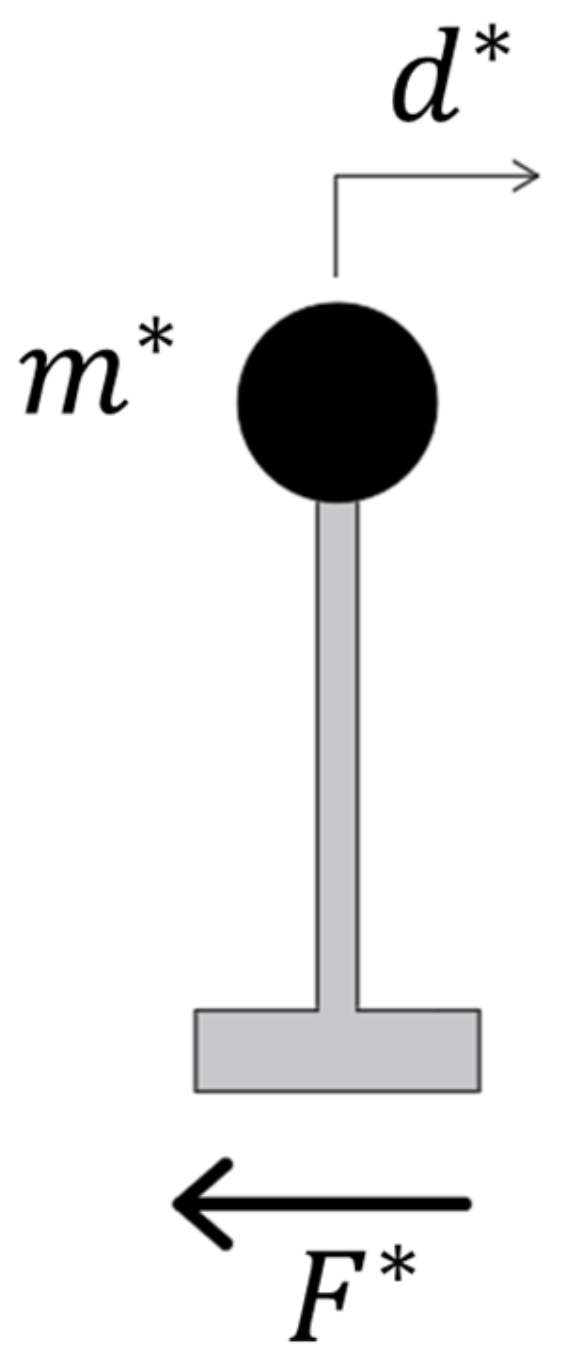
Figure 1. Equivalent Single-Degree-of-Freedom structural system.
Applsci 14 02684 g001
Figure 2. Definition of the equivalent bilinear curve according to Commentary to IBC [31].
Applsci 14 02684 g002
Figure 3. Structural plan of the case study structures (dimensions in m).
Applsci 14 02684 g003
Figure 4. Elevation views of the case study structures with indication of the inter-story height and cross-sections of the structural elements (dimensions in m).
Applsci 14 02684 g004
Figure 5. Reinforcement arrangement of the case study structures.
Applsci 14 02684 g005
Figure 6. Capacity curves in X and Z directions for (a) a 3-story building and (b) a 6-story building with indication of the performance point with target displacement dp.
Applsci 14 02684 g006
Figure 7. Layout of the retrofitted case study structures.
Applsci 14 02684 g007
Figure 8. Force–deflection curves of the steel brace (B) and of the damper (D) assumed in the study.
Applsci 14 02684 g008
Figure 9. Modelling approach of beams and columns.
Applsci 14 02684 g009
Figure 10. Design spectra (ξ = 5%) for the municipalities of Benevento and Tramutola for the two considered limit states.
Applsci 14 02684 g010
Figure 11. Comparison between the SDOF bilinear capacity curves of the 6-story structure retrofitted with damped braces with μDB = 9 and the damped demand spectra.
Applsci 14 02684 g011
Figure 12. Comparison of maximum displacements at each floor of the 6-story building retrofitted with damped braces with μDB = 9 obtained from the different non-linear analyses.
Applsci 14 02684 g012
Figure 13. Comparison of d/dTH,N for the case study structures; the curves refer to (a) results from NLSAs with actual η; (b) results from NLSAs with ηIBC; (c) results from NLTHA,A.
Applsci 14 02684 g013
Figure 14. Comparison of Δ/ΔTH,N for the case study structures; the curves refer to (a) results from NLSAs with actual η; (b) results from NLSAs with ηIBC; (c) results from NLTHA,A.
Applsci 14 02684 g014
Figure 15. Comparison of V/VTH,N for the case study structures; the curves refer to (a) results from NLSAs with actual η; (b) results from NLSAs with ηIBC; (c) results from NLTHA,A.
Applsci 14 02684 g015
Table 1. Properties of damped braces for different values of KB/KD and μD.
μD (-)KB/KD = 2KB/KD = 3KB/KD = 4KB/KD = 5
μDB (-)ξDB (%)μDB (-)ξDB (%)μDB (-)ξDB (%)μDB (-)ξDB (%)
43.042.43.344.13.444.93.545.5
64.349.04.850.35.050.95.251.3
85.752.46.353.56.654.06.854.3
107.054.67.855.48.255.98.556.2
128.356.09.356.89.857.210.257.4
149.757.110.857.711.458.111.858.3
1611.057.912.358.513.058.813.558.9
43.042.43.344.13.444.93.545.5
64.349.04.850.35.050.95.251.3
Disclaimer/Publisher’s Note: The statements, opinions and data contained in all publications are solely those of the individual author(s) and contributor(s) and not of MDPI and/or the editor(s). MDPI and/or the editor(s) disclaim responsibility for any injury to people or property resulting from any ideas, methods, instructions or products referred to in the content.