Abstract
This in vitro study evaluated the surface roughness (Sa) of two high-strength silicate ceramics, lithium disilicate IPS e.max CAD, Ivoclar Vivadent (LDS group), and zirconia-reinforced lithium silicate Vita Suprinity, VITA Zahnfabrik (ZLS group). The surface roughness was investigated before and after milling using different polishing systems and timings relative to the final crystallization of the ceramics. Forty-eight samples per group were polished by a single calibrated operator using two polishing systems: Dialite LD (Brasseler) and Lithium Silicate Polishers (Meisinger) for the LDS group and Dialite LD (Brasseler) and Vita Suprinity Polishing Set Technical (VITA Zahnfabrik) for the ZLS group, both pre- and post-crystallization. Surface roughness was measured using a confocal laser microscope (OLS4000 LEXT/Olympus), with scanning electron microscopy (SEM) used to evaluate surface morphological changes. Significant differences in Sa values were found between baseline groups, with ZLS exhibiting lower values. All polishing methods significantly reduced surface roughness compared to baseline (p ≤ 0.05). No significant differences were found in LDS samples when polishing pre- or post-crystallization (p = 0.129), while for ZLS samples, post-crystallization polishing achieved significantly smoother surfaces (p < 0.001). The study concluded that the choice of polishing system and timing did not significantly affect surface roughness for LDS. However, it is recommended that post-crystallization polishing be performed for the optimal smoothness of ZLS. This study aimed to evaluate the post-milling polishing procedures of CAD/CAM high-strength restorations, emphasizing the importance of an optimal surface roughness to prevent issues such as increased risk of abrasion on opposing teeth, enhanced plaque adhesion, and mechanical failures. Investigating these polishing techniques enables clinicians to optimize clinical performance, thereby improving the quality and longevity of high-strength silicate ceramics.
1. Introduction
Since the first dental chairside computer-aided design/computer-aided manufacturing (CAD/CAM) system was introduced in the mid-1980s by Mormann [1], interest in this innovative technology has garnered widespread adoption and has become part of everyday dentistry worldwide [2]. CAD/CAM systems have revolutionized the dental field, offering speed, precision, and efficiency in fabricating dental restorations. The process consists of digital scanning, designing (CAD), and milling (CAM) of restorations, assisted by a 3D scanner, computer software, and a milling machine [3]. Utilizing CAD/CAM technology offers several advantages, including improved accuracy and reduced manufacturing time. This process enables the production of an indirect dental restoration using a fully digital workflow inside the dental office, enabling same-day delivery restorations [4,5]. Additionally, the process eliminates the need for traditional impressions, temporary restorations, and assistance from external dental laboratories, streaming the delivery process and eliminating the need for a second appointment [6,7].
CAD/CAM materials used to fabricate dental restorations vary significantly in their properties, and indications and can be classified according to the nature of their composition and glass-to-crystalline ratio. These include glass-based CAD/CAM systems that contain mainly silicon dioxide also known as feldspars (e.g., CEREC Blocs C, Dentsply Sirona, Hanau, Germany; and Vitablocks Mark II, VITA Zahnfabrik, Bad Säckingen, Germany); leucite-reinforced ceramics (e.g., IPS Empress CAD, Ivoclar Vivadent, Schaan, Liechtenstein); lithium disilicates (e.g., IPS e.max CAD, Ivoclar Vivadent, Schaan, Liechtensteinl; LiSi Block, GC America, Alsip, IL, USA); and Amber Mill, HASS, Gwahakdanji-ro, Korea); and zirconia-reinforced lithium silicate (e.g., Celtra Duo, Dentsply Sirona, Hanau, Germany; Vita Suprinity PC, VITA Zahnfabrik, Bad Säckingen, Germany; and CEREC Tessera, Dentsply Sirona, Charlotte, NC, USA) to polycrystalline glass-free zirconia (e.g., InCoris TZI, Dentsply Sirona, Charlotte, NC, USA) [8,9].
High-strength silicate ceramics, such as lithium disilicates (LDS) and zirconia-reinforced lithium silicates (ZLS), have gained popularity in the dental field, balancing aesthetic demands with excellent mechanical properties. Their enhanced physical properties, including fracture toughness and resistance to chipping, makes them suitable for use in areas subjective to high masticatory forces, such as posterior teeth, and for long-span dental bridges, as well as implant-supported restorations. Its wide range of indications associated with excellent aesthetic qualities, including translucency, as well as color matching that closely mimics natural tooth enamel, making them one of the proffered choices for dental restorations [10].
Monolithic CAD blocks of lithium disilicate are marketed in a fully sintered but partially crystallized state. This state, often called the “blue/purple stage”, is characterized by the presence of 40% platelet-shaped lithium metasilicate (Li2SiO3) crystals, evenly dispersed in a glassy matrix. In this intermediate state, the lithium disilicate exhibits reduced mechanical properties. This reduction in hardness facilitates the milling process, making it easier and faster, as well as helping to minimize excessive wear of diamond burs or damage of the material. However, it is only after the heat process of final crystallization in a dental furnace that the lithium metasilicate crystals transform into a denser, larger-grained lithium disilicate, thereby achieving their final, excellent mechanical and optical properties [11,12].
Regardless of the chosen restorative material, milled restorations are considered to have rough surfaces, requiring finishing and polishing procedures prior to delivery [13]. The CAM process is based on the controlled reduction of premanufactured CAD/CAM blocks using diamond burs to achieve the desired final shape of the restorations. This procedure inherently results in insufficient surface smoothness for ideal clinical application [14,15].
Rough surfaces can lead to increased abrasion on opposing teeth, promote dental plaque adhesion, and heighten the risk of inflammation surrounding periodontal tissues [16,17,18,19,20,21]. Additionally, surface roughness can compromise the optical properties of restorations, affecting color stability and light reflection [22,23]. Moreover, surface irregularities resulting from the milling process can lead to stress concentrations in the ceramic, fostering the formation of microcracks that may propagate and undermine the final mechanical strength of the ceramic restoration [24,25]. Therefore, post-milling procedures are imperative to achieve the ideal surface finish before the restoration is delivered.
Dentists must ensure the proper surface smoothness of CAD/CAM restorations to remove scratches, flaws, or microcracks caused by the milling, thus preventing crack initiation and propagation [26]. Both mechanical polishing and fire-glazing processes are effective for achieving smoother surfaces. Mechanical polishing, a chairside procedure utilizing polishers and pastes, is quicker and does not require special equipment or additional firing cycles [27,28,29,30,31]. Most articles documenting the effectiveness of mechanical polishing of high-strength ceramics have been conducted after the crystallization process [32,33,34,35]. Research on the effectiveness of polishing devices and techniques for adjusting and re-polishing zirconia-reinforced lithium silicate is limited. Therefore this in vitro study aimed to evaluate the surface roughness of two high-strength silicate CAD/CAM ceramics post-milling and post-polishing, using three different polishing systems, both pre- and post-final crystallization.
2. Materials and Methods
Two high-strength CAD/CAM ceramics, lithium disilicate (LDS) (IPS e.max CAD, Ivoclar Vivadent, Schaan, Liechtensteinl;) and zirconia-reinforced lithium silicate (ZLS) (Vita Suprinity, VITA Zahnfabrik, Bad Säckingen, Germany), were used in this study. The ceramic groups of each material were polished by same calibrated operator using 2 different polishing systems before and after crystallization. For the LDS group, Dialite LD (Brasseler, Savannah, GA, USA) and lithium silicate polishers (Meisinger, Centennial, CO, USA) were used, and for the ZLS, Dialite LD (Brasseler) and Suprinity Polishing Set Technical (VITA Zahnfabrik, Bad Säckingen, Germany) were used (Table 1).

Table 1.
Contouring and polishing materials used in the study.
The evaluation of surface roughness for both ceramic groups utilized the (Sq) parameter, which is based on the square root average. These measurements were taken after polishing procedures, both when polished before and after the final crystallization of all sample groups. To ensure consistency across all samples, an Ivorine molar along with the adjacent teeth was altered to achieve a flat and broad horizontal surface. The modified preparation was digitalized using a CEREC Omnicam SW 5.2 (Dentsply Sirona, Charlotte, NC, USA). Subsequently, the sample design was finalized using the biogeneric copy mode, as depicted in Figure 1. The sample was dimensionally verified with a digital caliper, measuring 12 × 14 × 5 mm3. The occlusal area provided a flat surface that accurately simulated the outermost layer of milled restorations. This surface was then selected as the focal point for the investigation.
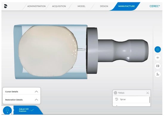
Figure 1.
Sample design using CEREC SW 5.2 (Dentsply Sirona).
Prior to the study, a power analysis was carried out to determine the appropriate sample size. Drawing from previous studies in the literature, an anticipated mean difference of 0.2 with an expected standard deviation of ±0.18 was assumed. The significance level was set to 5%. To achieve a statistical power of 80%, the calculation yielded a sample size of 10 per group. However, to allow for any potential errors, a total of twelve (12) samples were randomly allocated into six groups for each material type.
A total of sixty (60) samples were prepared for each of the two monolithic CAD/CAM materials: lithium disilicate (LDS) and zirconia-reinforced lithium silicate (ZLS). The machining of these samples was performed using a Sirona MCXL milling machine (Dentsply Sirona, Bensheim, Germany). To ensure consistency, the diamond cylinder pointed bur 12S and step bur 12S used to mill the samples were replaced before the commencement of the machining process and subsequently every 15 milling cycles.
Immediately following the milling procedure, which was performed at standard speed in fine mode, the baseline surface roughness values (Sa and Sq) for both materials, LDS and ZLS, were recorded, and Group 1 was designed as the negative control group, wherein they had their surface roughness values noted at this stage. Subsequently, the final crystallization process for the samples was conducted using the same dental furnace (Programat CS, Ivoclar Vivadent), adhering to the manufacture’s specifications for each material type. After crystallization, surface roughness values were recorded for Group 2, which served as the positive control group (baseline after crystallization). The remaining ninety-six (96) samples were distributed among into the final four groups (Groups 3, 4, 5, and 6). The allocation was based on the polishing system used and the timing of the procedure, whether polishing was performed before or after the final crystallization. All groups and their respective treatment protocols are detailed in Table 2.
Table 2.
Study design and groups.
All samples were polished by the same calibrated operator following standard protocols and the respective manufacturer’s recommendations. The polishing procedures incorporated the progressive use of two-step extra-oral polishers—one for pre-polishing and another for achieving a high shine (see Figure 2). These steps were conducted with a straight handpiece attached to a low-speed electric motor (Forza ELM, Brasseler, Savannah, GA, USA) to ensure a consistent rotational speed. Speeds varied from 6000 to 12,000 rpm, with each step lasting exactly 40 s under moderate pressure, without the use of diamond polishing paste or water cooling, culminating in a precise 80 s polishing protocol for each sample, as detailed in Table 3.
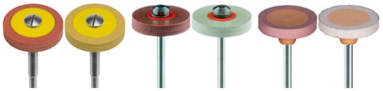
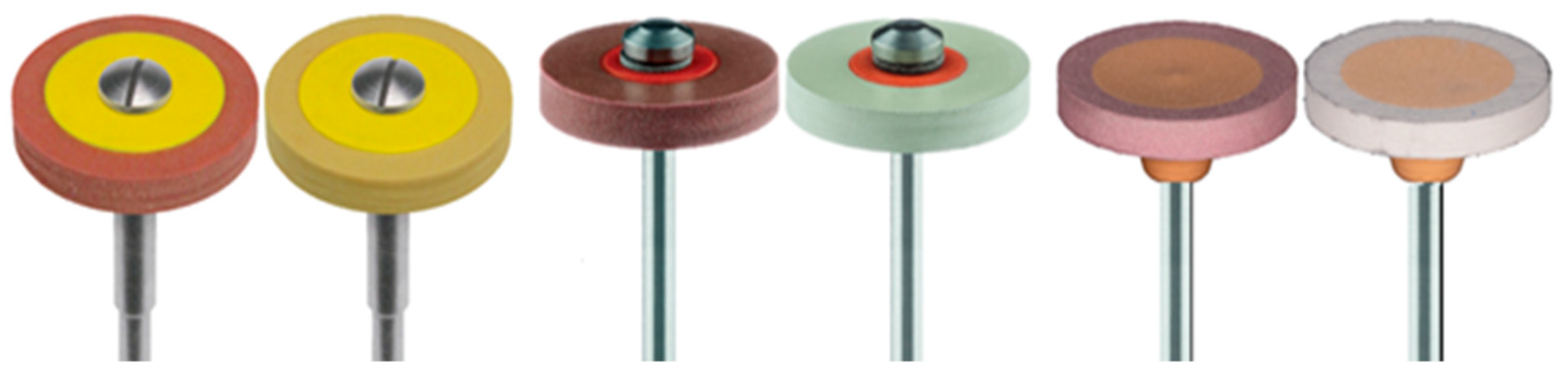
Figure 2.
Silicate wheel polishers, from left to right: Brasseler Dialite LD, pre-polishing and high gloss; Meisinger polishing wheels for silicate ceramics, pre-polishing and high shine; and Vita Suprinity polishing set technical, pre-polishing and high gloss.
Table 3.
Polishing protocols per group.
Before conducting surface roughness measurements, all specimens were subjected to ultrasonic cleaning in distilled water for 5 min to eliminate any residual debris that could potentially affect the readings. Post-cleaning, samples were air-dried for 10 s. Surface roughness was then quantified using a three-dimensional (3D) confocal laser microscope (OLS4000 LEXT, Olympus, Center Valley, PA, USA).
The unevenness of the ceramic surface was assessed by using the expansion of the well-known two-dimensional (2D) parameters (Ra and Rq) to three-dimensional (3D) parameters: The Sa parameter (arithmetic mean height) represents the 3D surface roughness, defined by the average deviation from the mean plane in the Z (x,y) coordinate system. And the Sq parameter (root mean square height) that reflects the 3D surface roughness by quantifying the standard deviation of surface height distribution within the measured area.
Surface roughness measurements for each sample were taken at the center of the specimen, over an area of 625 μm × 625 μm, using a 20× magnification under a laser light microscope. Given that higher magnification results in narrower visual field range, an advanced image stitching technique was employed to overcome this limitation. This method enables the software to amalgamate four individually measured adjacent areas into one comprehensive image, effectively creating an extended field of view measuring 1.2 mm by 1.2 mm. Besides calculating the arithmetic means, visual images of the surfaces were captured to qualitatively assess the surface roughness.
Means and standard deviations of surface roughness were calculated for each group.
Data were then subjected to a comparative analysis using one-way ANOVA (analysis of variance) to test if there was a difference amongst group means. Since multiple comparisons can increase the probability of false positives, the Tukey HSD test was applied with the significance level set at α = 0.05. The non-parametric Mann–Whitney U test was also applied to compare the distributions of two independent materials, LDS and ZLS, within the same group to evaluate a statistically significant difference in their median values.
3. Results
The means and standard deviations for surface roughness at baseline, before and after complete crystallization of the samples of lithium disilicate (LDS) and zirconia-reinforced lithium silicate (ZLS), are presented in Table 4.
Table 4.
Mean and standard deviation of Sa (arithmetic mean height) values of all groups and the Tukey HSD significance test. Values with different letters were significantly different from each other (p < 0.05). The Mann–Whitney U test was used to compare the distributions of the two independent materials, with p < 0.05 values for all groups.
The one-way ANOVA revealed a statistically significant difference in the mean 3D roughness values between the baseline groups (see Table 5). The Tukey multiple comparisons test, applied at the 0.05 significance level, was used to determine the statistical differences (p < 0.05) between LDS and ZLS, both before and after crystallization.
Table 5.
One-way ANOVA. Values with different letters were significantly different from each other (p < 0.05).
The CAD milling process led to a notable increase in surface roughness post-removal from the MC XL milling machine (Dentsply Sirona), establishing the baseline for both materials (p ≤ 0.05). At this baseline, ZLS exhibited overall lower surface roughness levels than LDS (p ≤ 0.05).
In the comparison within the same material, LDS showed slightly smoother values after the crystallization process; however, the difference in the mean surface roughness (Sa) values before and after the final firing cycle was not statistically significant. Conversely, ZLS experienced a significant reduction in surface roughness following the final crystallization process, even without any polishing procedure (p ≤ 0.05).
The statistical analysis via one-way ANOVA confirmed that all polishing procedures enhanced the smoothness of the surfaces of the high-strength silicate ceramics under study (p ≤ 0.05). To identify statistically significant differences between the polishing sequences and between the materials, Tukey’s test with multiple comparison was employed at the 0.05 significance level. The results, including the means, standard deviations, and statistical significance of surface roughness before and after final crystallization, are detailed in Table 4.
For lithium disilicate (LDS) samples, one-way ANOVA revealed that the differences in polished surface roughness (Sa) values before and after crystallization and in between the two different polishing systems were not significant at the level of 0.05 (refer to Figure 4). The omnibus test of differences across the four categories indicated no significant difference (p = 0.129), rendering a subsequent Tukey test unnecessary for this material.
In contrast, for zirconia-reinforced lithium silicate (ZLS), the one-way ANOVA demonstrated significant differences among the four groups. A Tukey test with multiple comparisons was conducted (p ≤ 0.05). It was found that surface roughness values were significantly reduced when polishing occurred after the final crystallization of ZLS blocks (p < 0.001). However, no significant differences were observed when comparing the effects of the Vita Suprinity and Brasseler polishing systems, both before (p = 0.910) and after (p = 0.968) crystallization, on the mean surface roughness (Sa) values (see Figure 5).
For a more detailed qualitative assessment, a scanning electron microscope (FE-SEM) (SU8000 in-line, Hitachi High-Tech, Tokyo, Japan) was employed. This instrument uses a focused beam of high-energy electrons to elucidate the external morphology (texture) based on electron-sample interactions. The advantage of SEM lies in its ability to produce images that reveal spatial variations at the surfaces of solid specimens, offering a more precise depiction of the surface roughness topography of the tested samples at an impressive magnification of 20,000×.
At baseline, all samples exhibited surface roughness levels that were excessively high for clinical applications. However, after undergoing post-milling procedures, either before or after the final crystallization process, there was a significant improvement in surfaces smoothness across all samples (p ≤ 0.05). For lithium disilicate (LDS), the timing of the post-milling procedures did not significantly affect surface roughness values (p = 0.129). In contrast, zirconia-reinforced lithium silicate (ZLS) samples showed a noticeable difference—surfaces polished before the crystallization were significantly rougher compared to those polished after the crystallization process.
4. Discussion
Surface roughness in ceramics is known to significantly influence stress concentration, fracture strength, plaque/bacterial adhesion, optics, and the final aesthetics of the material [17,18,19,20,36]. For CAD/CAM materials, roughness is affected by the geometry and grain size of the milling tools used in the subtractive milling process. In this study, samples were milled with a MC XL milling machine, utilizing two 64-micron grit diamonds burs operating simultaneously. The resulting surfaces were not as smooth as required for optimal clinical applications. It was observed that both lithium disilicate (LDS) and zirconia-reinforced lithium silicate (ZLS) displayed significant roughness values after milling (baseline) and after final crystallization. This indicates the necessity for post-milling procedures to achieve the desired clinical smoothness [37].
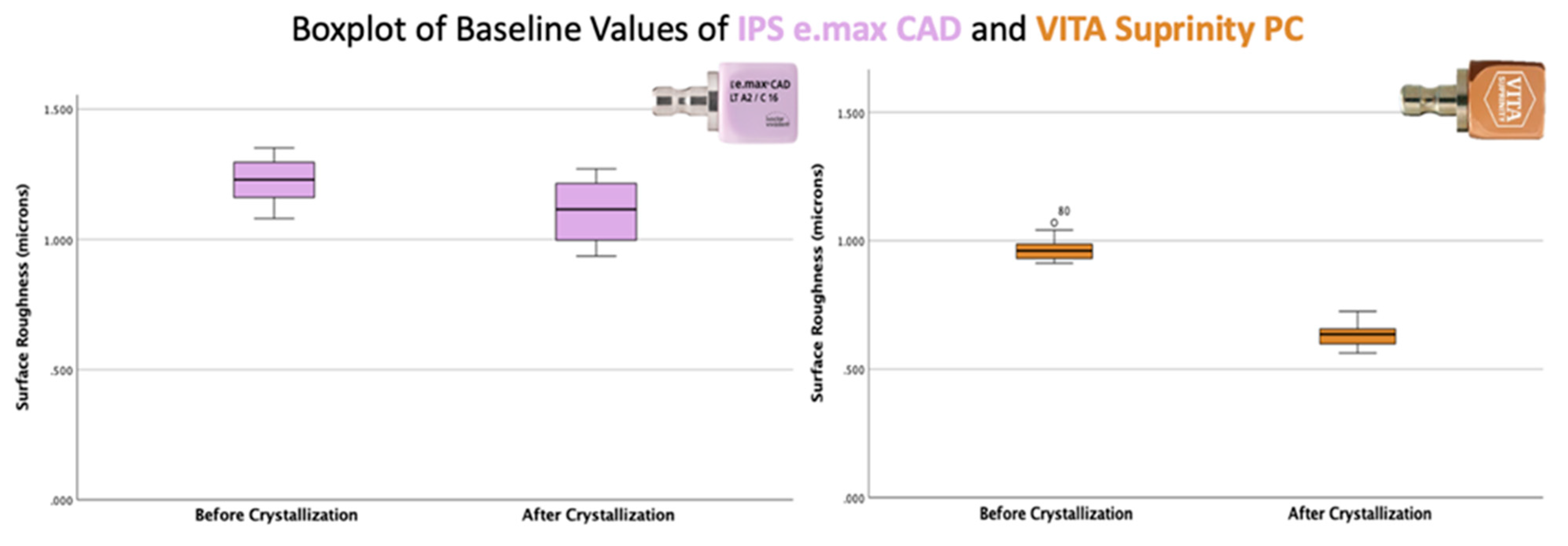
At the baseline, before and after crystallization, LDS did not exhibit significant differences in Sa roughness values (p = 0.009), implying that the material’s surface roughness remained relatively consistent throughout the crystallization process. On the other hand, ZLS showed significantly lower roughness values compared to LDS, both before and after crystallization (p < 0.001). The discovery of statistically significant differences in baseline roughness between the two materials leads to the rejection of the first null hypothesis (refer to Figure 3).
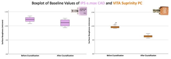
Figure 3.
The Y axis represents surface roughness values (Sa) in microns, and the X axis represents baseline groups for both materials, IPS e.max CAD and Vita Suprinity PC, before and after the final crystallization of the samples.
The observed differences in mean surface roughness between the materials can be attributed to their distinct microstructures and individual characteristics, such as the type and size of the crystalline phase [35]. Furthermore, the crystallization process itself significantly contributed to the reduction of surface roughness in ZLS. Previous studies by Lawson et al. (2016) [29] and Riquieri et al. (2018) [38] have previously reported that the flow of the vitreous component during the crystallization heat treatment could “heal” potential cracks or minute defects incurred during milling, which would explain the smoother surface observed in ZLS post-crystallization. However, despite the improvements noted, the roughness values obtained from the confocal laser microscopy (referenced in Table 4) and SEM micrographs evaluation (Figure 4 and Figure 5) still indicate that the surface smoothness does not meet the ideal standards for clinical performance.
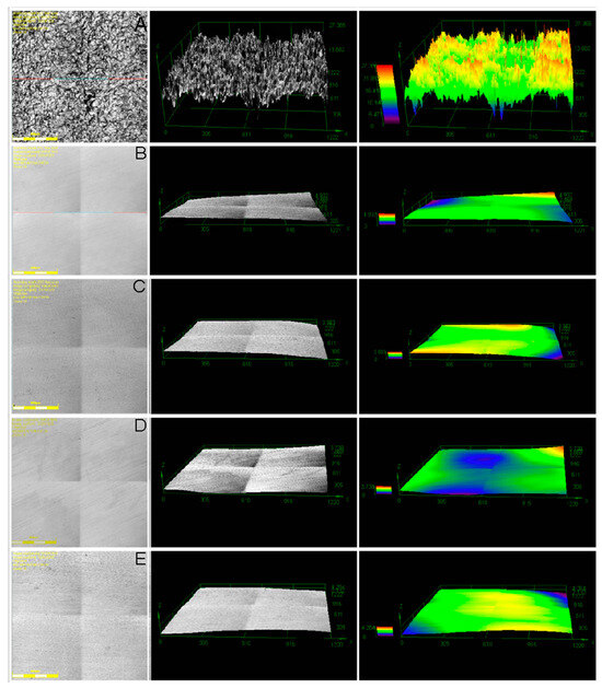
Figure 4.
IPS e.max CAD—two-dimensional (2D) and three-dimensional (3D) micrographs produced by Olympus LEXT OLS4100 Confocal Laser Scanning Microscope. (A) IPS e.max CAD after milling (baseline) with surface roughness more apparent, (B) LDS polished using Brasseler pre-crystallization, (C) LDS polished using Brasseler post-crystallization, (D) LDS polished using Meisinger pre-crystallization, and (E) LDS polished using Meisinger post-crystallization.
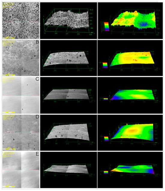
Figure 5.
VITA Suprinity PC—two-dimensional (2D) and three-dimensional (3D) micrographs produced by Olympus LEXT OLS4100 Confocal Laser Scanning Microscope. (A) Suprinity PC after milling (baseline), (B) ZLS polished using Brasseler pre-crystallization, (C) ZLS polished using Brasseler post-crystallization, (D) ZLS polished using VITA Suprinity set pre-crystallization, (E) ZLS polished using VITA Suprinity set post-crystallization.
While there are extensive reports on various techniques, systems, and high-strength ceramic materials, much of the literature on surface roughness has relied on either contact or non-contact (2D) profilometers. In this study, roughness was measured using a cutting-edge technique with a 3D measuring confocal laser microscope (OLS4000 LEXT by Olympus). This 3D microscope allows for a comprehensive evaluation within the defined area by expanding upon the traditional 2D roughness parameters (Ra and Rq), represented by Sa (arithmetic mean height) and Sq (root mean square height), calculated from the average values of Z (x,y) within the measured area. The advantage of using the 3D laser microscope lies in its ability to measure a larger area with high-resolution imagery, offering a more representative assessment compared to linear roughness evaluations.
Therefore, the second objective of this study was to assess and compare the effectiveness of different extra-oral polishing systems (Brasseler, Meisinger, and Vita Polishers) in terms of 3D roughness, both before and after the final crystallization of two high-strength silicate ceramics, lithium disilicate (LDS) and zirconia-reinforced lithium silicate (ZLS).
For the LDS groups (3, 4, 5, and 6), a one-way ANOVA revealed that the differences in polished roughness values of LDS, both pre- and post-crystallization, as well as between the Brasseler and Meisinger polishing systems, were not statistically significant (p = 0.129). Consequently, the second null hypothesis was not rejected, indicating that no additional data comparison was warranted for LDS.
The polishing effectiveness for LDS, evaluated with the surface roughness parameters Sa and Sq, showed no significant variance, neither before nor after crystallization, nor between the two different polishing systems used. This outcome aligns with the manufacturer’s claim that post-milling procedures for lithium disilicate (IPS e.max CAD) are equally effective at any stage of crystallization. This provides clinical and technical reassurance that post-milling procedures for IPS e.max CAD can be performed at whichever stage is most convenient, without compromising efficiency or performance.
In contrast, for the ZLS groups (3, 4, 5, and 6), the one-way ANOVA indicated significant differences among the four groups. Subsequent analysis using the Tukey multiple comparisons test revealed significant disparities when polishing was conducted before versus after crystallization within the same polishing system, as illustrated in Figure 6.
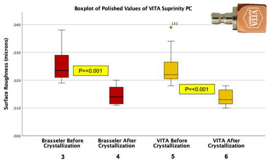
Figure 6.
The Y axis represents the surface roughness value (Sq) in microns, and the X axis represents the polished groups of Vita Suprinity PC, either by Brasseler or Vita Polishers, before and after final crystallization of the samples.
ZLS groups displayed significantly lower values of surface roughness (Sa) when polishing was performed after the final crystallization of the material (p < 0.001). Both polishers, Brasseler and Vita polishers, provided a significantly smoother surface when they polished after final crystallization of the samples, without a significant difference among the two. Therefore, for ZLS (Vita Suprinity PC), the recommendation is that the polishing procedure should be performed post-crystallization to achieve significantly better performance in the means of surface roughness.
This difference in surface roughness of ZLS, polished before and after crystallization, can be attributed to its pre-crystallized composition. This composition includes a porous glassy matrix with embedded round and submicrometric elongated grains of lithium metasilicates and lithium orthophosphates, alongside tetragonal zirconia fillers [39]. As described by Kruger et al. (2013) [40] and Aurelio et al. (2016) [41], the absence of crystalline zirconia post-crystallization suggests that ZrO2 remains amorphous and integrated within the glassy matrix, enhancing the material’s optical properties. However, polishing prior to the final crystallization may remove these metasilicate and orthophosphate crystals from the restoration’s outer layer, as well as displace ZrO2 particles from the matrix.
This can result in a rougher surface, even after the vitreous component has melted and crystallization is complete.
When assessing the efficiency of the two different polishing kits, Brasseler and Vita Suprinity Polishing Set, no statistically significant differences were observed in surface roughness means, both pre- and post-crystallization (p = 0.910 before/p = 0.968 after). Furthermore, both polishing kits yielded significantly improved results when used after the final crystallization of the zirconia-reinforced lithium silicate (ZLS) samples, with a p value of <0.001.
In the evaluation of the final surface roughness across all polished groups, ZLS that was polished post-crystallization achieved lower areal roughness values (Sa and Sq) compared to any polished lithium disilicate (LDS) group. However, no significant differences were found between LDS (both pre- and post-crystallization) and post-crystallization ZLS.
These findings align with those of Vichi et al. (2018) [34], who also examined and compared monolithic LDS and ZLS using a similar methodology, albeit assessing linear surface roughness parameters (Ra and Rq) and employing different polishing systems.
5. Conclusions
Within the limitations of this in vitro study, the following conclusions can be drawn:
- Chairside polishing of lithium disilicate (IPS e.max CAD) and zirconia-reinforced lithium silicate (Vita Suprinity PC) without the use of diamond polishing paste effectively reduced surface roughness in silicate CAD/CAM ceramics, regardless of whether it took place before or after the final crystallization.
- When polishing timing was assessed, no significant differences were detected, neither before nor after final crystallization of IPS e.max CAD.
- The timing of the post-milling procedure was a critical factor in the 3D surface roughness for Vita Suprinity PC. Polishing before crystallization led to significantly rougher surface textures than polishing after crystallization. Therefore, the polishing procedure of ZLS is recommended to be carried out after the final crystallization stage of the material.
- Among the three polishing systems tested, no significant differences were observed in their ability to smooth both materials. LDS and ZLS when polished post-crystallization exhibited comparable polishability, with no significant variances in 3D surface smoothness values.
Author Contributions
Conceptualization, F.T.R.; Methodology, F.T.R. and G.d.F.N.; Software, P.H.-F.; Validation, A.V. and P.H.-F.; Formal analysis, M.V. and G.d.F.N.; Investigation, F.T.R.; Resources, P.H.-F.; Data curation, F.T.R. and A.V.; Writing—original draft, F.T.R.; Writing—review & editing, A.V. and G.d.F.N.; Supervision, A.V. and G.d.F.N.; Project administration, G.d.F.N.; Funding acquisition, F.T.R. and G.d.F.N. All authors have read and agreed to the published version of the manuscript.
Funding
This research was funded by the LeGRO Internal Funding Award.
Institutional Review Board Statement
Not applicable.
Informed Consent Statement
Not applicable.
Data Availability Statement
The original contributions presented in the study are included in the article, further inquiries can be directed to the corresponding authors.
Conflicts of Interest
The authors declare no conflicts of interest.
References
- Mörmann, W.H.; Brandestini, M.; Lutz, F.; Barbakow, F. Chairside Computer-Aided Direct Ceramic Inlays. Quintessence Int. 1989, 20, 329–339. [Google Scholar] [PubMed]
- Kelly, J.R.; Benetti, P. Ceramic Materials in Dentistry: Historical Evolution and Current Practice. Aust. Dent. J. 2011, 56 (Suppl. S1), 84–96. [Google Scholar] [CrossRef] [PubMed]
- Suganna, M.; Kausher, H.; Ahmed, S.T.; Alharbi, H.S.; Alsubaie, B.F.; Ds, A.; Haleem, S.; Ali, A.B.M.R. Contemporary Evidence of CAD-CAM in Dentistry: A Systematic Review. Cureus 2022, 14, e31687. [Google Scholar] [CrossRef] [PubMed]
- Moörmann, W.H. The Evolution of the CEREC System. J. Am. Dent. Assoc. 2006, 137, 7S–13S. [Google Scholar] [CrossRef] [PubMed]
- Santos, G.C., Jr.; Santos, M.J., Jr.; Rizkalla, A.S.; Madani, D.A.; El-Mowafy, O. Overview of CEREC CAD/CAM Chairside System. Gen. Dent. 2013, 61, 36–41. [Google Scholar] [PubMed]
- Fasbinder, D.J. Computerized Technology for Restorative Dentistry. Am. J. Dent. 2013, 26, 115–120. [Google Scholar]
- Beuer, F.; Schweiger, J.; Edelhoff, D. Digital Dentistry: An Overview of Recent Developments for CAD/CAM Generated Restorations. Br. Dent. J. 2008, 204, 505–511. [Google Scholar] [CrossRef] [PubMed]
- Shenoy, A.; Shenoy, N. Dental Ceramics: An Update. J. Conserv. Dent. 2010, 13, 195–203. [Google Scholar] [CrossRef]
- Conrad, H.J.; Seong, W.-J.; Pesun, I.J. Current Ceramic Materials and Systems with Clinical Recommendations: A Systematic Review. J. Prosthet. Dent. 2007, 98, 389–404. [Google Scholar] [CrossRef]
- Babu, P.J.; Alla, R.K.; Alluril, V.R.; Datla, S.R.; Konakanchi, A. Dental Ceramics: Part I—An Overview of Composition, Structure and Properties. Am. J. Mater. Eng. Technol. 2015, 3, 13–18. [Google Scholar]
- Li, R.W.; Chow, T.W.; Matinlinna, J.P. Ceramic dental biomaterials and CAD/CAM technology: state of the art. J. Prosthodont. Res. 2014, 58, 208–216. [Google Scholar] [CrossRef] [PubMed]
- Lien, W.; Roberts, H.W.; Platt, J.A.; Vandewalle, K.S.; Hill, T.J.; Chu, T.-M.G. Microstructural Evolution and Physical Behavior of a Lithium Disilicate Glass–Ceramic. Dent. Mater. 2015, 31, 928–940. [Google Scholar] [CrossRef] [PubMed]
- Song, X.-F.; Ren, H.-T.; Yin, L. Machinability of Lithium Disilicate Glass Ceramic in In Vitro Dental Diamond Bur Adjusting Process. J. Mech. Behav. Biomed. Mater. 2016, 53, 78–92. [Google Scholar] [CrossRef] [PubMed]
- Yara, A.; Ogura, H.; Shinya, A.; Tomita, S.; Miyazaki, T.; Sugai, Y.; Sakamoto, Y. Durability of Diamond Burs for the Fabrication of Ceramic Crowns Using Dental CAD/CAM. Dent. Mater. J. 2005, 24, 134–139. [Google Scholar] [CrossRef] [PubMed]
- Wittneben, J.-G.; Wright, R.F.; Weber, H.-P.; Gallucci, G.O. A Systematic Review of the Clinical Performance of CAD/CAM Single-Tooth Restorations. Int. J. Prosthodont. 2009, 22, 466–471. [Google Scholar] [PubMed]
- Jagger, D.C.; Harrison, A. An In Vitro Investigation into the Wear Effects of Unglazed, Glazed, and Polished Porcelain on Human Enamel. J. Prosthet. Dent. 1994, 72, 320–323. [Google Scholar] [CrossRef] [PubMed]
- Amer, R.; Kürklü, D.; Kateeb, E.; Seghi, R.R. Three-Body Wear Potential of Dental Yttrium-Stabilized Zirconia Ceramic after Grinding, Polishing, and Glazing Treatments. J. Prosthet. Dent. 2014, 112, 1151–1155. [Google Scholar] [CrossRef]
- Rashid, H. The Effect of Surface Roughness on Ceramics Used in Dentistry: A Review of Literature. Eur. J. Dent. 2014, 8, 571–579. [Google Scholar] [CrossRef]
- Saiki, O.; Koizumi, H.; Akazawa, N.; Kodaira, A.; Okamura, K.; Matsumura, H. Wear Characteristics of Polished and Glazed Lithium Disilicate Ceramics Opposed to Three Ceramic Materials. J. Oral Sci. 2016, 58, 117–123. [Google Scholar] [CrossRef]
- Sainan, Z.; Li, J.; Lei, Z.; Liying, H.; Lu, Y.; Wei, L. Influence of Surface Roughness on Oral Streptococcal Adhesion Forces to Dental Filling Materials. West China J. Stomatol. 2016, 34, 448–453. [Google Scholar] [CrossRef]
- Matzinger, M.; Hahnel, S.; Preis, V.; Rosentritt, M. Polishing Effects and Wear Performance of Chairside CAD/CAM Materials. Clin. Oral Investig. 2019, 23, 725–737. [Google Scholar] [CrossRef] [PubMed]
- Awad, D.; Stawarczyk, B.; Liebermann, A.; Ilie, N. Translucency of Esthetic Dental Restorative CAD/CAM Materials and Composite Resins with Respect to Thickness and Surface Roughness. J. Prosthet. Dent. 2015, 113, 534–540. [Google Scholar] [CrossRef] [PubMed]
- Kurt, M.; Güngör, M.B.; Nemli, S.K.; Bal, B.T. Effects of Glazing Methods on the Optical and Surface Properties of Silicate Ceramics. J. Prosthodont. Res. 2020, 64, 202–209. [Google Scholar] [CrossRef] [PubMed]
- Maciel, L.C.; Silva, C.F.B.; de Jesus, R.H.; Concílio, L.R.d.S.; Kano, S.C.; Xible, A.A. Influence of Polishing Systems on Roughness and Color Change of Two Dental Ceramics. J. Adv. Prosthodont. 2019, 11, 215–222. [Google Scholar] [CrossRef] [PubMed]
- Ludovichetti, F.S.; Trindade, F.Z.; Adabo, G.L.; Pezzato, L.; Fonseca, R.G. Effect of Griding and Polishing on the Roughness and Fracture Resistance of Cemented CAD-CAM Monolithic Materials Submitted to Mechanical Aging. J. Prothet. Dent. 2019, 121, 866.e1–866.e8. [Google Scholar] [CrossRef]
- Curran, P.; Cattani-Lorente, M.; Wiskott, H.A.; Durual, S.; Scherrer, S.S. Grinding damage assessment for CAD-CAM restorative materials. Dent. Mater. 2017, 33, 294–308. [Google Scholar] [CrossRef] [PubMed]
- Amin, M. Comparison of Surface Hardness between Polished, Glazed and Unpolished Porcelain Surfaces. Master’s Thesis, Marmara Universitesi, Istanbul, Turkey, 1998. [Google Scholar]
- Heintze, S.D.; Cavalleri, A.; Forjanic, M.; Zellweger, G.; Rousson, V. Wear of Ceramic and Antagonist—A Systematic Evaluation of Influencing Factors In Vitro. Dent. Mater. 2008, 24, 433–449. [Google Scholar] [CrossRef]
- Lawson, N.C.; Janyavula, S.; Syklawer, S.; McLaren, E.A.; Burgess, J.O. Wear of Enamel Opposing Zirconia and Lithium Disilicate after Adjustment, Polishing and Glazing. J. Dent. 2014, 42, 1586–1591. [Google Scholar] [CrossRef]
- Akar, G.C.; Pekkan, G.; Çal, E.; Eskitaşçıoğlu, G.; Özcan, M. Effects of Surface-Finishing Protocols on the Roughness, Color Change, and Translucency of Different Ceramic Systems. J. Prosthet. Dent. 2014, 112, 314–321. [Google Scholar] [CrossRef]
- Martínez-Gomis, J.; Bizar, J.; Anglada, J.M.; Samsó, J.; Peraire, M. Comparative Evaluation of Four Finishing Systems on One Ceramic Surface. Int. J. Prosthodont. 2003, 16, 74–77. [Google Scholar]
- Kang, S.-H.; Chang, J.; Son, H.-H. Flexural Strength and Microstructure of Two Lithium Disilicate Glass Ceramics for CAD/CAM Restoration in the Dental Clinic. Restor. Dent. Endod. 2013, 38, 134–140. [Google Scholar] [CrossRef] [PubMed]
- Mota, E.G.; Smidt, L.N.; Fracasso, L.M.; Burnett, L.H., Jr.; Spohr, A.M. The Effect of Milling and Postmilling Procedures on the Surface Roughness of CAD/CAM Materials. J. Esthet. Restor. Dent. 2017, 29, 450–458. [Google Scholar] [CrossRef]
- Vichi, A.; Fonzar, R.F.; Goracci, C.; Carrabba, M.; Ferrari, M. Effect of Finishing and Polishing on Roughness and Gloss of Lithium Disilicate and Lithium Silicate Zirconia Reinforced Glass Ceramic for CAD/CAM Systems. Oper. Dent. 2018, 43, 90–100. [Google Scholar] [CrossRef] [PubMed]
- Mohammadibassir, M.; Rezvani, M.B.; Golzari, H.; Salehi, E.M.; Fahimi, M.A.; Fard, M.J.K. Effect of Two Polishing Systems on Surface Roughness, Topography, and Flexural Strength of a Monolithic Lithium Disilicate Ceramic. J. Prosthodont. 2019, 28, E172–E180. [Google Scholar] [CrossRef] [PubMed]
- Abdalla, M.M.; Ali, I.A.; Khan, K.; Mattheos, N.; Murbay, S.; Matinlinna, J.P.; Neelakantan, P. The Influence of Surface Roughening and Polishing on Microbial Biofilm Development on Different Ceramic Materials. J. Prosthodont. 2021, 30, 447–453. [Google Scholar] [CrossRef] [PubMed]
- Bollenl, C.M.; Lambrechts, P.; Quirynen, M. Comparison of Surface Roughness of Oral Hard Materials to the Threshold Surface Roughness for Bacterial Plaque Retention: A Review of the Literature. Dent. Mater. 1997, 13, 258–269. [Google Scholar] [CrossRef] [PubMed]
- Riquieri, H.; Monteiro, J.B.; Viegas, D.C.; Campos, T.M.B.; de Melo, R.M.; Saavedra, G.d.S.F.A. Impact of Crystallization Firing Process on the Microstructure and Flexural Strength of Zirconia-Reinforced Lithium Silicate Glass-Ceramics. Dent. Mater. 2018, 34, 1483–1491. [Google Scholar] [CrossRef]
- Zarone, F.; Ruggiero, G.; Leone, R.; Breschi, L.; Leuci, S.; Sorrentino, R. Zirconia-Reinforced Lithium Silicate (ZLS) Mechanical and Biological Properties: A Literature Review. J. Dent. 2021, 109, 103661. [Google Scholar] [CrossRef]
- Krüger, S.; Deubener, J.; Ritzberger, C.; Höland, W. Nucleation Kinetics of Lithium Metasilicate in ZrO2-Bearing Lithium Disilicate Glasses for Dental Application. Int. J. Appl. Glas. Sci. 2013, 4, 9–19. [Google Scholar] [CrossRef]
- Aurélio, I.L.; Dorneles, L.S.; May, L.G. Extended Glaze Firing on Ceramics for Hard Machining: Crack Healing, Residual Stresses, Optical and Microstructural Aspects. Dent. Mater. 2017, 33, 226–240. [Google Scholar] [CrossRef]


Disclaimer/Publisher’s Note: The statements, opinions and data contained in all publications are solely those of the individual author(s) and contributor(s) and not of MDPI and/or the editor(s). MDPI and/or the editor(s) disclaim responsibility for any injury to people or property resulting from any ideas, methods, instructions or products referred to in the content. |
© 2024 by the authors. Licensee MDPI, Basel, Switzerland. This article is an open access article distributed under the terms and conditions of the Creative Commons Attribution (CC BY) license (https://creativecommons.org/licenses/by/4.0/).