Article

Design and On-Orbit Performance of the Payload Rack Thermal Management System for China Space Station Experimental Lab Module

1
School of Energy Science and Engineering, Harbin Institute of Technology, Harbin 150001, China
2
Technology and Engineering Center for Space Utilization, Chinese Academy of Sciences, Beijing 100094, China
*
Authors to whom correspondence should be addressed.
Appl. Sci. 2024, 14(7), 2938; https://doi.org/10.3390/app14072938
Submission received: 11 February 2024 / Revised: 4 March 2024 / Accepted: 11 March 2024 / Published: 30 March 2024
(This article belongs to the Section Fluid Science and Technology)

Abstract

:
An efficient and reliable spacecraft payload thermal management method is one of the key problems to build China Space Station (CSS). Aiming at the outstanding characteristics and difficulties of the payloads rack in the experimental lab module of CSS, in the aspects of thermal control interface, boundary constraint, scale quantity, space layout, diversity of temperature control, operation mode and working life, etc., a two-stage thermal management scheme based on single-phase fluid loop is proposed and constructed. A fluid drive unit is designed to drive the fluid circulation and health management of the module thermal control bus (TCB). In view of the different characteristics of the payload racks, three different types of second-stage thermal control systems are proposed, and different thermal control terminals are designed, in order to solve the problem of thermal control resource allocation and health management in payload racks. A method based on “pump bypass” and “valve resistance ratio” is used to control the flow rate of the thermal management system. Based on the overall scheme of the thermal management system and the developed flight products, on-orbit verification and data analysis are carried out. Flight verification shows that the key parameters of the fluid loop in the thermal management system on orbit are basically consistent with the ground data; the maximum deviation is 1.84%. The pressure control accuracy of the bypass system reaches ±2%, and the active heat transfer efficiency of the integrated thermal management system is over 83%, which can effectively meet the thermal control requirements of the two-stage payloads in the module and rack. After on-orbit flight verification, the designed thermal control system works well on orbit and exhibits good stability.

1. Introduction

A thermal control system is an important part of a spacecraft, being directly related to the safety, reliability and function of the spacecraft and load. Since international space exploration began in the 1950s, early spacecraft formed passive thermal control techniques, which are mainly represented by a multi-layer thermal insulation component, heat pipe, thermal control coating, etc. Assisted by an electric heater, the traditional thermal control system has achieved relatively stable results in the long-term space thermal control field [1]. This kind of thermal control system has many advantages, such as simple composition, high reliability, light weight, low cost, short development cycle, etc.; therefore, it is widely used in conventional aircraft [2,3,4].
As the need to explore space continues to grow, the load scale and temperature control requirements of large spacecraft, such as target spacecraft, space laboratories, space stations and moon and deep space probes, have reached unprecedented levels [5,6,7]. The traditional thermal control methods cannot meet the work needs of spacecraft, and a new active thermal control system based on the concept of thermal management is proposed. Because of the strong ability regarding adjustment and adaptation, high efficiency of heat transfer, high precision of temperature control and strong ability of upgrade and expansion, it has become the main method of thermal control for large spacecraft in the world. New thermal control technologies such as single-phase fluid loop driven by pump, two-phase fluid loop, convective ventilation, space heat pump and consumable heat sink, etc., provide the technical basis for the integrated thermal control of complex large spacecraft [8,9].
Different types of thermal management systems have been developed in conjunction with the construction of large spacecraft [10]. Since the 1990s, the International Space Station (ISS) has been built on orbit for more than 20 years by countries including the United States, Europe, Japan, Russia, Italy, etc. [11]. A total of 33 payload racks were installed in the four experimental modules of the ISS. According to the load characteristics and requirements of different modules, an integrated heat management system with single-phase fluid loop and different configurations is constructed [12]. Due to the lack of consideration of global load characteristics and working mode in the early stage of construction, the thermal control system of some modules has some limitations in the practical application on orbit [13]. “Destiny” used a medium–low temperature double fluid loop to adjust the load and heat, and a closed-loop method was used to adjust the temperature and flow rate outside the rack dynamically. After on-orbit verification, because each branch of the system has strong coupling characteristics, the current closed-loop control method based on flow and temperature is not suitable for a large number of parallel fluid systems. The thermal control system of the module experienced major parameter oscillation during the operation mode conversion, which was improved by updating the control algorithm on orbit [14]. Because the thermal control system in the rack is set to a fixed manual regulation mode, the regulation range between the loads in the rack is affected by the pressure difference outside the rack and the resistance characteristics of the regulation terminal; thus, it is impossible to realize on-orbit dynamic fine regulation between the loads in the rack [15,16]. In the “European Columbus”, a parallel single-phase fluid loop is used as a thermal management tool to regulate the total pressure of the system based on the frequency conversion of the pump [17], resulting in less independence of thermal control resource regulation between loads. If the pump speed is adjusted frequently, the robustness, stability and component reliability of the large-scale system will be reduced. Based on the experience of large-scale spacecraft thermal management systems, there are many problems in thermal control system principle construction and precise stability control.
In the early 2000s, China began to build its own space station, with an unprecedented number of scientific experiments planned for rolling out implementation over the next 10 to 15 years [18]. Compared with the payload inside a conventional spacecraft, the heat sources in the modules of CSS represented by the scientific experiment racks are characterized by large scale, wide space layout, multi-level thermal control, diverse demand for temperature control, complex working mode and long life on orbit [19]. Problems such as maintenance, upgrade and extension and replacement of loads on orbit pose a great challenge to the thermal control of the whole module and the internal loads of the rack. The collection, transmission and dispersion of waste heat generated by the payloads in the space station module need to solve the overall configuration design of a complex large-scale thermal control system and establish and verify an efficient and stable control method. The traditional thermal control system and operation mechanism cannot satisfy the thermal control demand of the experimental lab module of CSS.
A new, reliable and efficient integrated thermal management system for the space station experimental payload module is constructed to meet the new thermal control application objectives, scientific requirements and mission guidance.
This paper focuses on the heat management problem of the payloads in China Space Station. The payload distribution characteristics, temperature control requirements and boundary constraints of CSS are analyzed in detail in Section 2. According to the requirements, a two-stage bus-type thermal control system based on single-phase fluid loop is constructed in Section 3. In Section 4, the General Control Method and theoretical model of the thermal control system are put forward, and the control characteristics of the system are analyzed with the working parameters of the pump valve. In Section 5, the system scheme and control method are verified on orbit for a special module of CSS, and the data analysis and evaluation of the fluid operation parameters, control characteristics and heat transfer characteristics of the thermal control system are carried out.

2. Payload Characteristics and Thermal Control Requirements

2.1. The Overall Distribution of Payloads in CSS

The initial plan for CSS included three sealed modules, the overall configuration is “T” shaped structure [20] and each module of CSS has a different number of payloads inside. Similar to the International Space Station (ISS), the payloads were mainly installed inside as standard-style racks; the number and spatial distribution of the racks in different modules of the space station are shown in Figure 1:
Taking module 2 as an example, there are seven payload racks in the module, which are used for scientific experiments in multidisciplinary fields. The system support rack is mainly used for the integrated power distribution, numerical control and thermal control of the payloads in the module. In addition, a new kind of rack is arranged for the verification of the new technology on orbit. It also contains two empty racks for the installation of subsequent uplink loads for CSS [21,22,23,24]. The total thermal power of the whole module is 5500 W, and the maximum power of a single rack is 2300 W. The space station platform provides the installation and heat exchange boundary for the experimental payload rack. The thermal environment and heat boundary inside the module are as shown in Figure 2, specific thermal boundary conditions are described as follows:
  • Heat conduction installation boundary
The heat source of the rack is installed in the module via hinged installation, and the installation point adopts the method of heat insulation as far as possible so as to reduce the heat transfer from the heat source of the rack to the module wall.
2.
Air convection environment
The natural convection heat transfer is obviously weakened in the micro-gravity environment of the payload rack in the module. The environmental control ventilation system in the module contacts the payload rack through the front surface for heat transfer.
3.
Radiation background environment
There is radiative heat exchange between the payload rack and the surroundings; the payload rack will radiate heat to the surrounding environment through surface and, at the same time, receive radiative heat from the surrounding equipment.
4.
The boundary of fluid heat dissipation
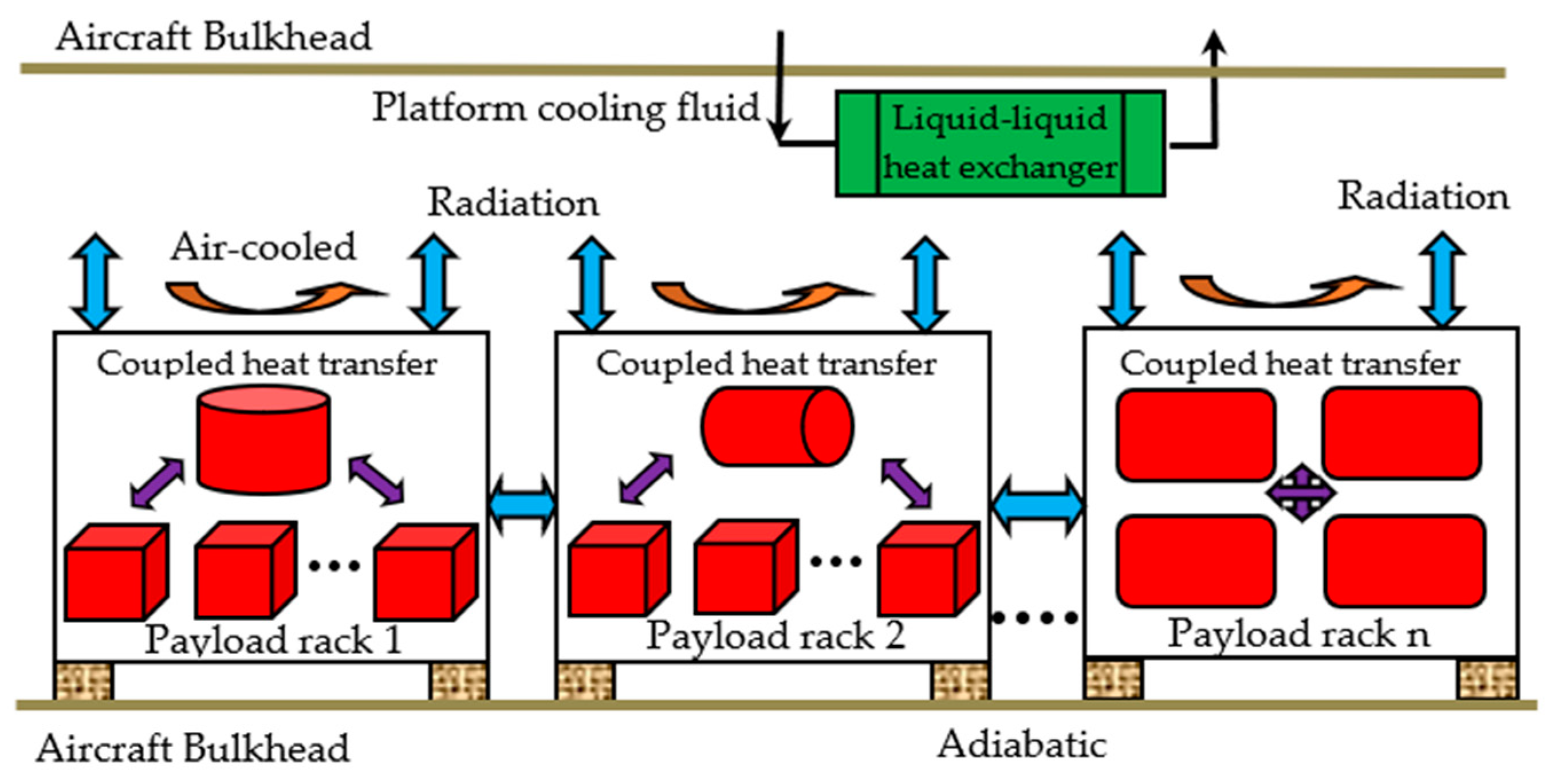
The payload racks in the module have the characteristics of large heat consumption and long-term work; the convective ventilation and radiation cannot meet the demand of heat dissipation. Therefore, the active thermal control resources available in the space station platform are used as the interface for the thermal management of the payload system.
Figure 2. Thermal environment and heat transfer path of payload rack.
Applsci 14 02938 g002

2.2. Thermal Characteristics of Payloads and Control Requirements

The payload racks in CSS are divided into several types according to their functions and working characteristics, which are suitable for different scientific and technical fields. As shown in Table 1, different payload racks present different characteristics and thermal control requirements. According to the layout of payload rack, some of the loads are installed in the form of standard drawer; the standard size of a single drawer is 450 mm × 560 mm × 173.5 mm. The rack can install up to eight standard drawers; individual load takes up maximum space of four standard drawers. In addition, some loads in individual fields are irregular non-standard structures that are installed inside the rack.
According to the function of the lab module, the total power consumption is in the range of 300–2300 W. In addition, the temperature of the conventional electronic equipment inside the module should be controlled in the range of −10–45 °C, the stability is controlled at ±5 °C/h, some low-temperature loads are required to work at (0–10)°C, optical loads are required to work at ±(0.5–1)°C/h and basic physics classes are required to work at mK/h level; the temperature difference cannot exceed 10 mk. In addition, some samples of space organisms and life-like organisms require a cryogenic storage environment, with temperature requirements ranging from −80 °C to 4 °C.
It can be seen that the payload rack is loaded with various kinds of scientific devices; different fields and devices have various requirements on temperature, and the load structure layout and on-orbit working mode reflect great differences. It is the key point of this paper to plan all kinds of load demands and put forward a hierarchical and classified thermal control system scheme and regulation method according to load characteristics.

3. Thermal Control System Scheme and Unit Design

3.1. Framework and Scheme

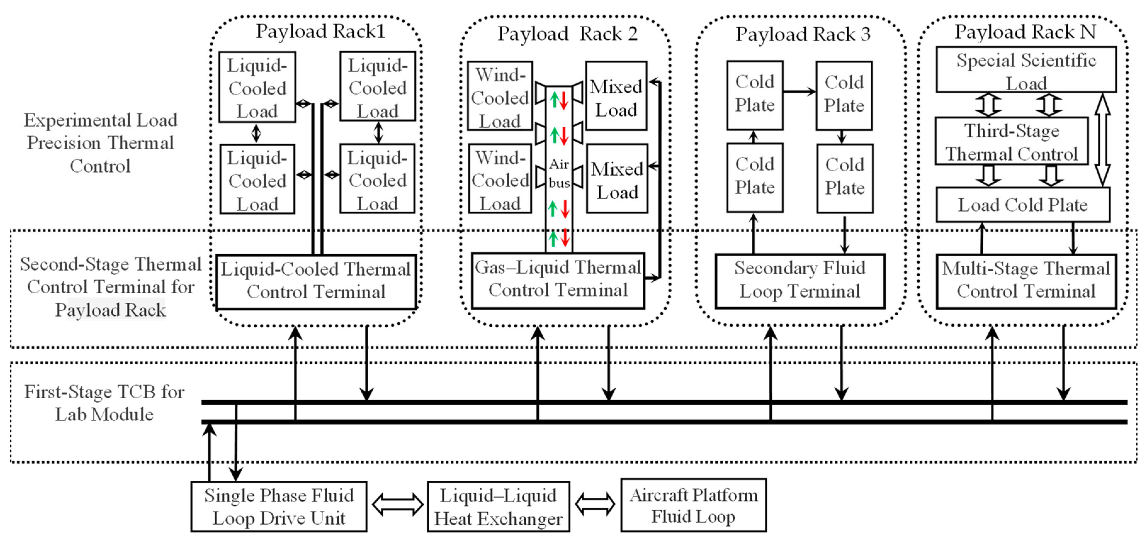
As shown in Figure 3, a three-stage thermal control system based on single-phase fluid loop was constructed to solve the problem of diversified thermal management of the payload inside the module of CSS. Firstly, the liquid–liquid heat exchanger provided by the platform is used as the heat sink of the thermal control system, and the fluid loop drive unit is used as the circulating power to construct the bus-type fluid pipe network in the module. A first-level thermal control bus (TCB) for the module is constructed, which conveys the cooling fluid (36% ethylene-glycol) to each payload rack; after the load heat is collected, it is conveyed to the Fluid Drive unit through a fluid pipeline network; finally, the heat is transferred to the thermal control loop of the aircraft platform by the liquid–liquid heat exchanger.
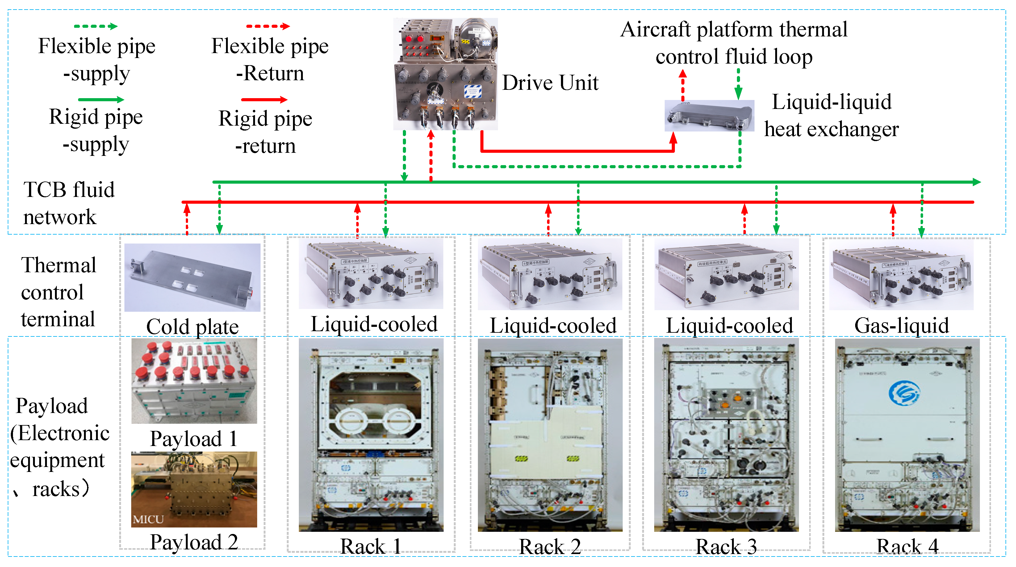
According to the payload racks, second-stage thermal control systems are built based on the liquid-cooled resources provided by first-stage TCB. Four kinds of thermal control management units of rack are designed: (a) liquid-cooled thermal control terminal, (b) gas–liquid thermal control terminal, (c) secondary fluid loop terminal and (d) multi-stage thermal control terminal. According to the thermal control demands of different racks, the thermal control terminal carries on the overall thermal control management regarding the rack and realizes the medium and heat exchange with the TCB. The product architecture of the thermal management system is shown in Figure 4:
Different modules of CSS adopt a unified thermal control design framework; each module is equipped with different thermal control terminals according to the number and type of actual payload rack; the fluid drive unit and thermal control terminals have a unified design.

3.2. First-Stage TCB

3.2.1. Operating Principle

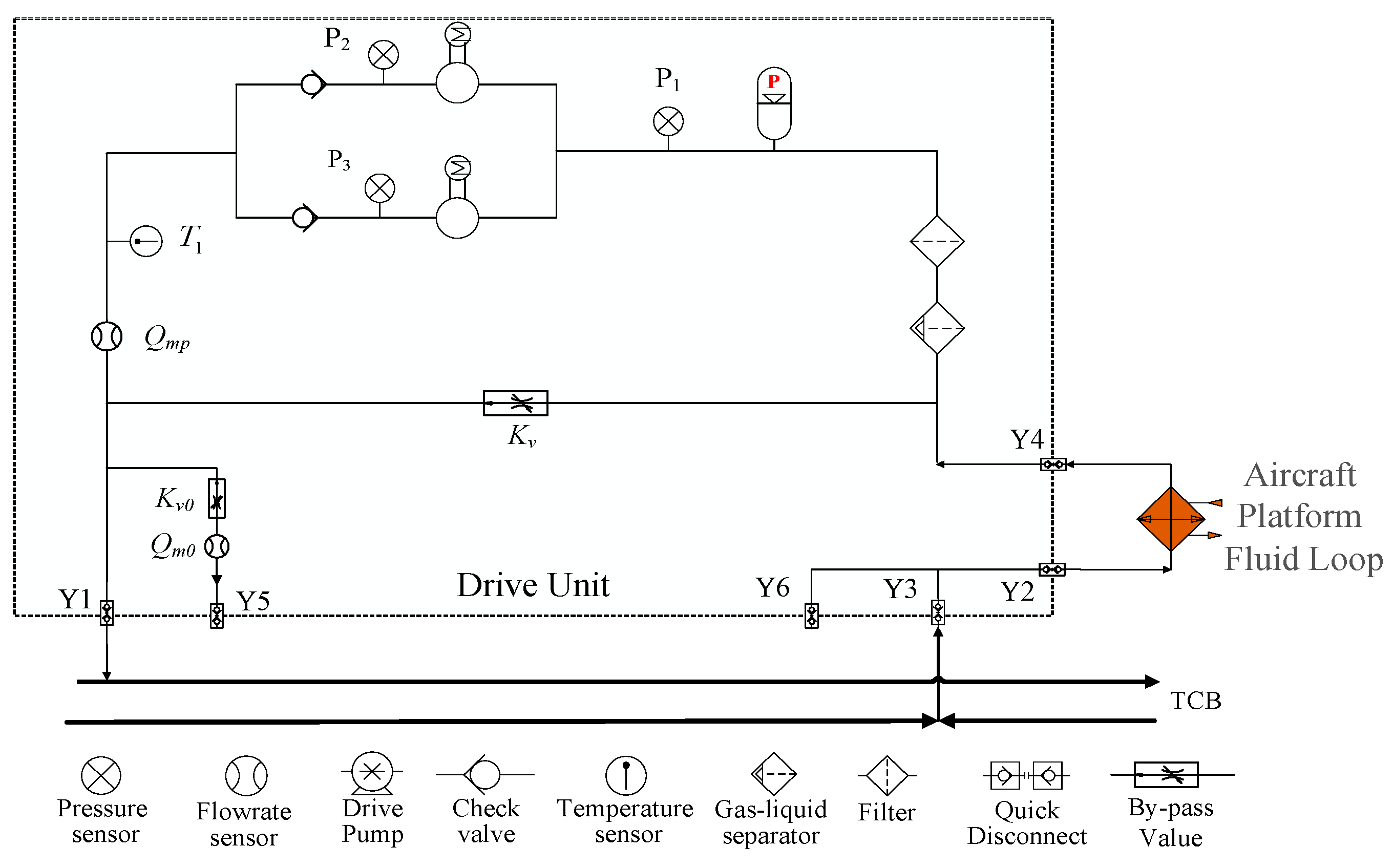
The TCB in the space station module is mainly composed of fluid drive unit and system pipe network, and the fluid drive unit, as the power unit of the bus, is mainly responsible for the fluid circulation drive and the health state management of the fluid system. As shown in Figure 5, the bus is driven by the centrifugal pump. The flow rate and pressure head are provided by the centrifugal pump. To avoid the backflow in the parallel system, a one-way valve is set at the outlet of the circulating pump. After the fluid is pressurized by the circulating pump, it flows through the one-way valve downstream. The flow rate is measured and monitored by the flowmeter based on the venturi tube principle and then output to the fluid bus in the module. After the heat is collected, the fluid returns to the drive unit to measure the temperature of the backwater, and the heat exchange will take place between TCB and the platform thermal control loop though the liquid–liquid heat exchanger.
A centrifugal gas–liquid separator is arranged inside the drive unit, and the separator is in the form of an inverted cone. The working fluid flows through the separator at a certain speed; under the action of the centrifugal force, the gas in the working fluid will gather in the center of the separator. In order to avoid the influence of impurities on the system, a filter is arranged in the system, and the filtering precision reaches 40 μm. In addition, a metal bellows-type energy storage device is placed at the entrance of the circulating pump; on the one hand, it can provide a constant inlet pressure for the system, and, on the other hand, it can compensate for the change in working fluid volume caused by the change in temperature, and it can also compensate for the micro-leakage during the long-term use of the system.
In order to control the pressure and output flow of the TCB and avoid major fluctuation of the system when changing the working mode in the module, the bypass valve of the system is set up to ensure the relative stability of the system pressure and pump output parameters.

3.2.2. Fluid Drive Device

The first-stage fluid TCB in the module adopts the design principles of miniaturization and modularization. The physical model of the drive unit is shown in Figure 6, all functional components, such as pumps, valves and sensors, are integrated into a standard drawer. Different sizes of quick disconnect are mounted to the front panel of the drawer, used for quick connection and disconnection of liquid pipes. In addition, in order to ensure the long-term work of the fluid bus on orbit, the pump, compensator, filter, electronics board and other key components are designed in accordance with the on-orbit replaceable unit (ORU) for replacement by the astronauts.

3.3. Second-Stage Thermal Control System inside the Rack

3.3.1. Operating Principle

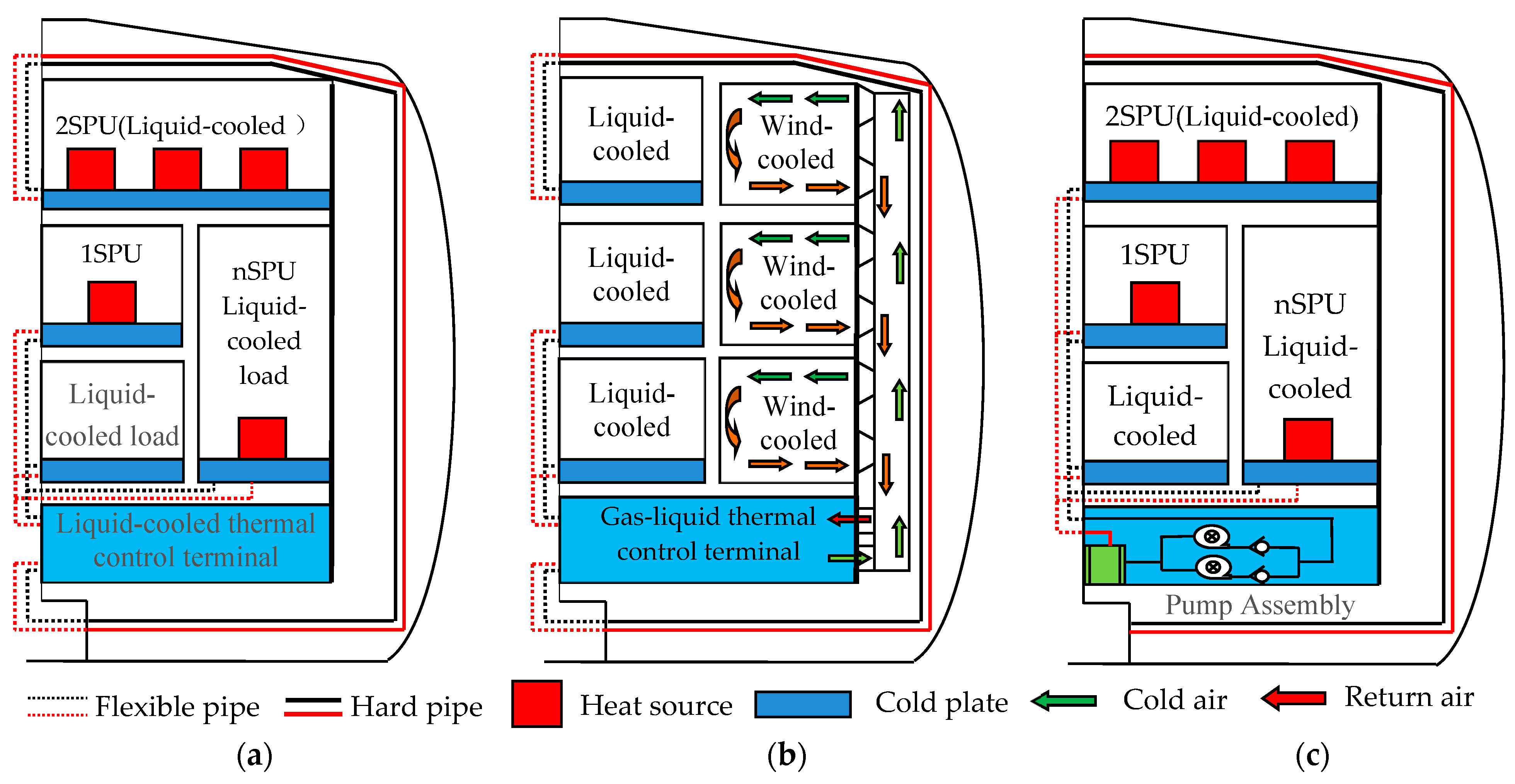
As shown, the payload rack is connected to the TCB through the quick disconnector on the front panel. The inner part of the payload rack directly utilizes the liquid cooling resources provided by the TCB, and the resources are redistributed through the liquid cooling and thermal control terminal, which matches the flow rate of each channel according to the heat consumption of each load inside the module; according to the load quantity in the module, the thermal control terminal is matched with 2–3 channels of liquid supply branch, which is dynamically adjusted through the internal electric valve and transported to each load through flexible hose; the internal heating equipment of each experimental load is installed on the plate-fin-type cold plate to conduct heat to the fluid loop.
As shown in Figure 7b, some racks adopt the method of gas–liquid mixed cooled; on the one hand, the medium of the TCB is provided to the cold plate for the equipment cooling. On the other hand, the heat source distribution of some loads inside the rack is relatively scattered, and the space size of the load is larger than others, which leads to low collection efficiency by using the liquid-cooled method, so an air loop bus is designed inside the rack; a set of parallel air ducts are arranged on the back of the rack to provide cold wind to scientific loads. The heat collected by the air loop is transferred to the liquid loop through the gas–liquid heat exchanger; the liquid loop eventually transfers the heat to the aircraft platform.
For payloads with large flow rate demand inside the rack, as shown in Figure 7c, a secondary fluid loop is designed to collect the internal load’s heat through an independent closed fluid loop; the flow rate can be adjusted by the rotation speed of the pump. After the heat of the secondary circuit is collected, the heat exchange with the TCB is realized through the liquid–liquid heat exchanger installed inside the rack.

3.3.2. Design of Thermal Control Terminal

The thermal control terminal is the key unit of the thermal control system in the payload rack; its main function is to receive and distribute the liquid cooling resources from the TCB according to the requirements of payload inside the rack. It is also used to monitor the health status and key parameters of the thermal control system. Three different types of thermal control terminals are designed: (a) liquid-cooled thermal control terminal; (b) gas–liquid thermal control terminal and (c) secondary fluid loop terminal. All the thermal control terminals are designed as standard drawers with dimensions of 456 mm × 560 mm × 173 mm.
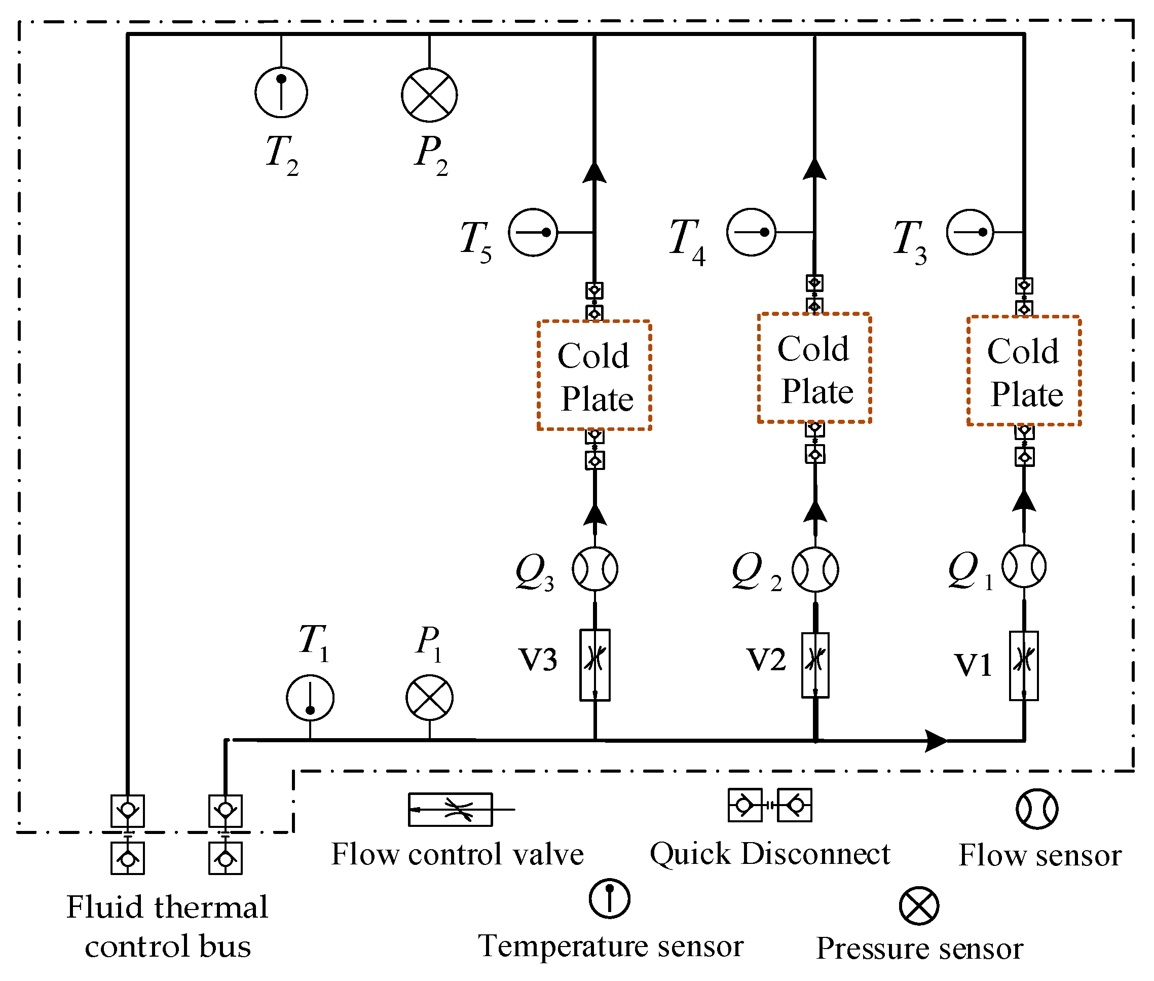
Figure 8 shows the working principle of the liquid-cooled thermal control terminal. The thermal control terminal connects to the TCB through quick disconnector, the fluid pipe is divided into 2–3 branches after the fluid medium enters the rack, a linear flow control valve is installed in each branch and the valve can be controlled by instruction to adjust the flow resistance of the branch. All branches are equipped with flow sensors to monitor and control the flow rate of working fluid; the inlet and outlet of the thermal control terminal are equipped with liquid temperature and pressure sensors to measure fluid parameters. Each branch of the thermal control terminal is provided with a working fluid inlet and outlet for connecting the cold plate of the load.
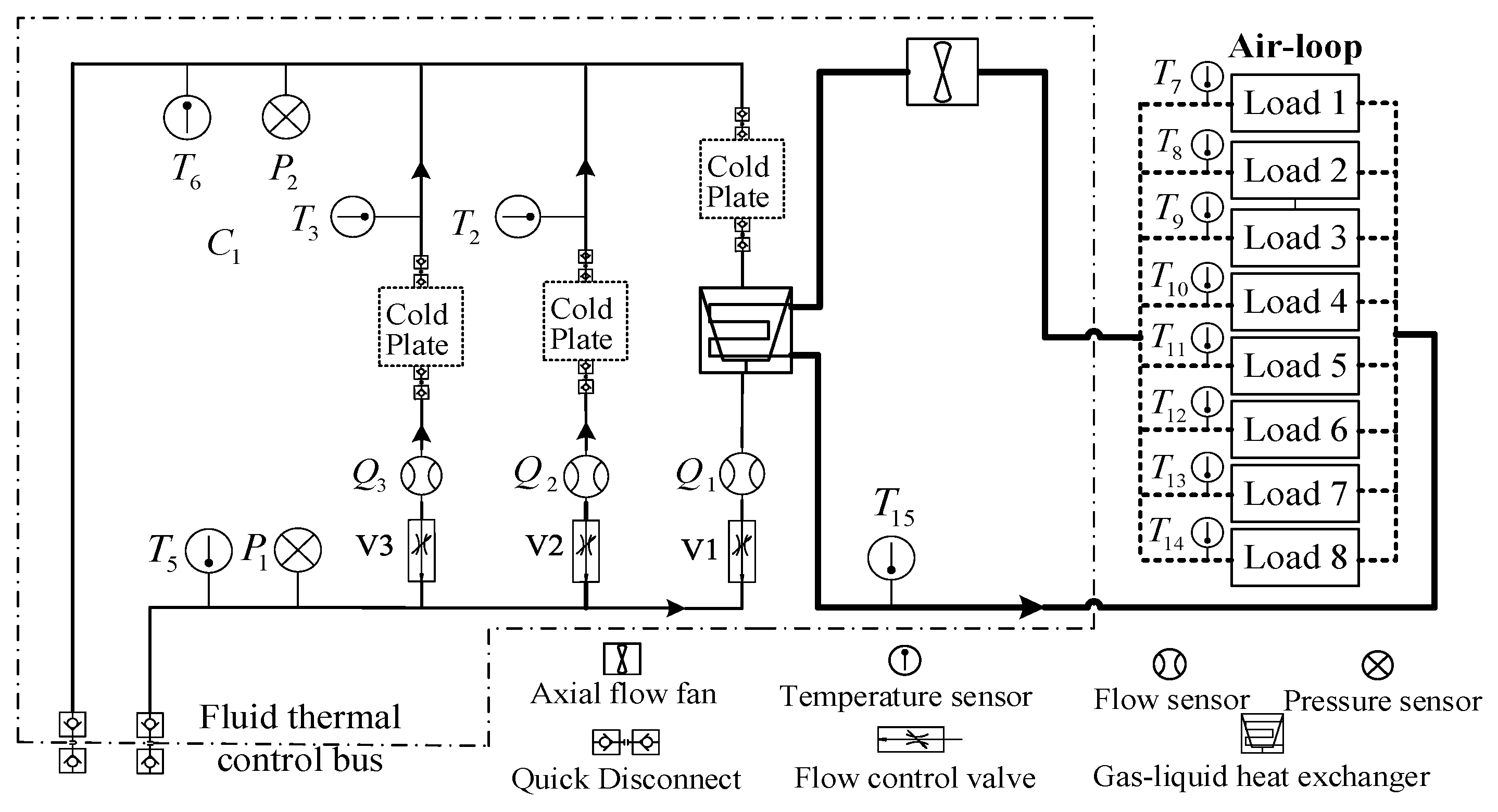
The design principle of gas–liquid mixed thermal control terminal is extended on the basis of liquid-cooled thermal control terminal. As shown is Figure 9, a gas–liquid heat exchanger is connected in series in the first branch to collect heat from the air loop. An axial flow fan is arranged inside the unit to provide circulating power for the air loop, which can provide maximum of 204 cm3/h air flow. The air loop provides eight parallel air supply interfaces; temperature sensors and air flow regulators are installed at the entrance of each branch.
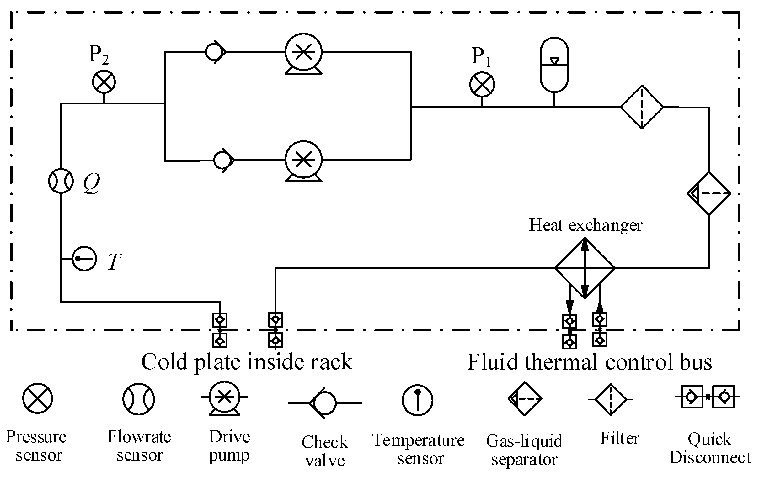
As shown in Figure 10, the design principle of secondary circuit thermal control terminal is basically consistent with that of TCB drive unit. A small pump assembly is arranged inside the device, and the pump can provide liquid flow rate in the range of 0–250 L/h and can provide a maximum of 80 kPa hydraulic head. A small liquid–liquid heat exchanger is arranged inside the device to provide the heat exchange interface between the secondary fluid loop of the rack and the TCB.

4. Regulation Method and Characteristics Analysis

4.1. Pump Bypass Model and Control Characteristics Subsection

For the parallel-bus-type single-phase fluid loop thermal control system, due to the large number of downstream terminals and the internal components, heat dissipation and resistance characteristics of various loads are not consistent. In addition, the power consumption and operating mode of each load are different, and the flow and temperature demand of each load branch will be different. The key to the optimal design and reliable operation of the thermal management system is to establish a stable and reliable control strategy and method to ensure high robustness and strong stability of the system under complex and variable conditions.
The TCB of single-phase fluid circuit is a multi-parallel branch thermal-fluid network driven by centrifugal pump, and the drive unit is the main power equipment of the system. It takes the role of providing the drive force for the fluid network and the basic control parameters of the bus, whose working characteristics determine the basic key parameters of the whole system, such as the operating pressure, the pressure difference and the flow rate. According to the design principles of the drive unit in Section 2, the abstract simplified model of the basic pressure flow characteristics is shown in Figure 11a below:
According to the design principle of the drive unit, the basic fluid network can be composed of the drive pump and the resistance element in the unit; equalize the components with fixed flow resistance coefficient such as flow sensor, filter, bubble capture and separation device, one-way valve, etc. The equivalent resistance characteristics model of the drive unit is
Δ P o = Δ P p ξ 1 + ξ 2 Q mp 2
where Δ P o is pressure difference in TCB (kPa); Δ P p is pressure difference in pump (kPa); ξ 1 is equivalent flow resistance coefficient of pump outlet; ξ 2 is equivalent flow resistance coefficient of pump inlet; Q mp is the flow rate of the pump.
From Formula (1), it can be concluded that the output pressure characteristics of the drive unit are related to the characteristics of the working point of the pump and the equivalent flow resistance coefficient of the main flow path. In order to ensure the relative independence and stability of the thermal control parameters between each rack when the thermal control system switches the operating conditions, a pump bypass structure is constructed to control and regulate the pressure of TCB.
If the working speed(n) of the drive pump is constant, the relationship between the output flow rate and the pressure difference between the inlet and outlet of the pump is
Δ P p = f p , n Q mp
When the flow rate of the thermal bus Q m o is adjusted in the range of [ Q mo , min , Q mo , max ], assuming that the thermal bus working pressure difference Δ P o is set in Δ P :
Δ P 0 = Δ P *
The flow pressure output characteristics of the drive pump at the rotational speed(n) are as follows:
Δ P p = f p , n Q mp
The relationship between the working flow rate of the drive pump and the pressure difference in the TCB is obtained as follows:
Δ P o = Δ P * = f o , n Q mp * = f p , n Q mp * ξ 1 + ξ 2 Q mp * 2
The operating parameters ( Q m p * , Δ P p * ) are determined. The speed of the drive pump needs to be increased to ensure Q m p * > Q mo , max .
As shown in Figure 11b, a bypass valve is used to optimize and modify the flow pressure curve of TCB in order to construct the ideal output characteristic; the bypass valve is used to compensate for the downstream flow resistance of the thermal bus; the inlet and outlet of the bypass valve are in the same position with the TCB. The main resistance element of the drive unit is connected in series with the drive pump and connected in parallel with the bypass valve. The actual flow characteristics of the bypass valve are as below:
Q m v = f v ( Δ P o , K v )
where K v is valve opening, Δ P o is pressure difference in TCB (pressure difference in bypass valve) and Q m v is flow rate through the bypass valve. The flow rate of the bypass valve shall be at least within the constant pressure regulating range of the TCB. Therefore, the limit flow rate of bypass valve in the TCB under extreme conditions is
Q mv , max = Q m p * Q mo , min = f v Δ P o * , K v , max Q mv , min = Q m p * Q mo , max = f v Δ P o * , K v , min
The ideal flow rate characteristics of bypass valve should be
Q m v = Q m v , max Q m v , min K v , max K v , min K v K v , min + Q m v , min , Δ P o = Δ P o *
where K v , max is maximum design opening of valve, K v , min is minimum design opening of valve; the flow rate at 100% valve opening is as follows:
Q M = 1 K v , min K v , max K v , min Q m v , max 1 K v , max K v , max K v , min Q m v , min
where Q M is flow rate when the valve opening is 100% and the pressure difference between the inlet and outlet is Δ P o . Combining Formula (8), the max flow rate is as follows:
Q M = 1 K v , min K v , max K v , min ( f o , n 1 ( Δ P o ) Q mo , min ) 1 K v , max K v , max K v , min ( f o , n 1 ( Δ P o ) Q mo , max )
As shown in Figure 11b and Formula (10), if Q m o > Q mo , max , the actual opening of the bypass valve is less than the minimum opening of the constant pressure zone; with the further reduction in the system flow resistance, the output flow rate of the drive pump Q m p increases obviously; the pressure difference between the drive pump Δ P p and the thermal bus Δ P o decreases; the flow rate of bypass valve reduces and the output flow rate of the drive unit Q m o increases. Load resistance characteristic curve continues to move to the right; the output pressure difference regarding TCB Δ P o is close to zero and the output flow rate Q m o is close to maximum.
When Q m o < Q mo , min , the bypass valve will reach its maximum opening, with the outlet flow resistance increasing; it will cause the flow of the pump Q m p to decrease; at the same time, the pressure difference between the drive pump Δ P p and TCB Δ P o will increase. This will cause the flow rate of bypass valve to increase and the output flow rate of the drive unit Q m o to reduce. When the outlet flow resistance increases to complete shutdown, the output flow rate of the drive pump Q m o is close to zero, and the output pressure difference in the drive pump Δ P o reaches the maximum value.
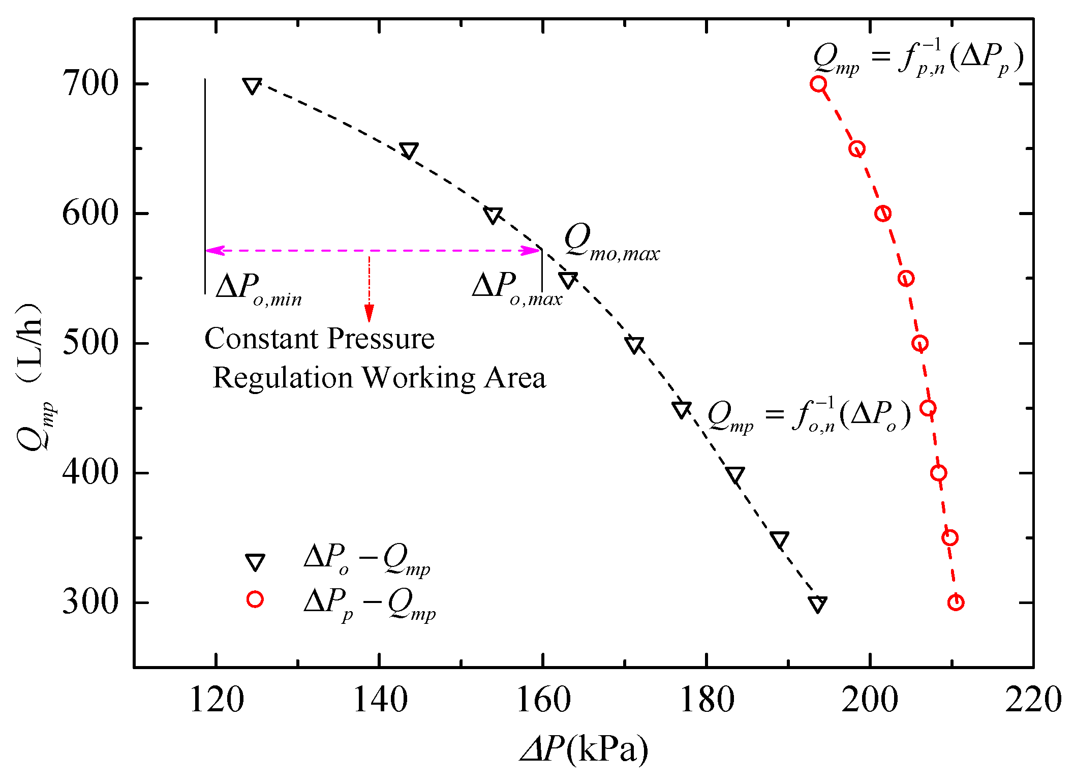
Figure 12 shows the output characteristic curve of the drive pump and drive unit. The drive pump selected in this paper is a kind of centrifugal shield pump. At a fixed speed, the output flow rate decreases as the flow resistance increases; the pressure head provided by the pump decreases as the output flow increases.
In combination with Figure 12 and Formula (10), the relationship between bypass valve characteristics and the control range of the TCB can be obtained according to the actual requirements of the thermal control system. It is assumed that the maximum linear adjustment flow rate of the TCB Q mo , max is a constant value; under different pressure differences in TCB, the linear adjustable range of flow rate is related to the characteristics of the bypass valve as follows:
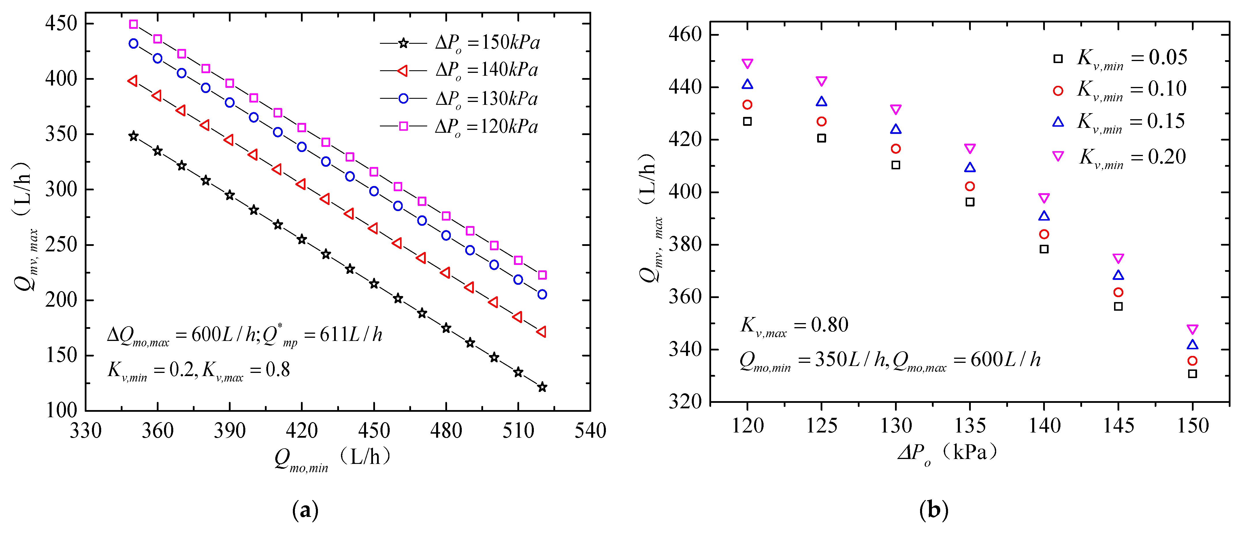
It can be concluded that the operating characteristics of the bypass valve have a great influence on the control range and the control ability of the TCB; when the maximum control flow rate and control opening range of the TCB under constant pressure are determined, the larger the flow rate at the maximum opening of the valve, the wider the control range of the TCB. As shown in Figure 13a, when the constant pressure of the TCB is set at 120 kPa, the flow rate at the maximum opening of the valve is 450 L/h, the regulating range is from 350 L/h to 600 L/h and the regulating range is 250 L/h. When the flow rate of the valve is 225 L/h at the maximum opening, the limit resistance coefficient of the valve increases obviously and the minimum regulating flow rate of the TCB rises to 520 L/h; under constant pressure, the regulation range of the constant pressure region was reduced to 80 L/h and the regulation ability was obviously reduced.
Under the same range of valve opening and maximum regulating flow rate, it can be seen from Figure 13b, with the increase in the working pressure difference in the TCB, the working flow rate of the drive pump decreases; the constant pressure control range of TCB increases obviously. If the flow resistance coefficient at maximum opening is maintained as a constant, it can be seen that, if the working pressure of the TCB is adjusted to 150 kPa, the minimum constant pressure regulating flow rate is 235 L/h; the regulation range under constant pressure increases to 365 L/h, which is a 46% increase from 120 kPa.
After the above analysis, the pump bypass structure can effectively control the output flow and pressure difference in the TCB; the control range of the flow rate of the system under constant pressure will be increased by increasing the working pressure of the TCB; at the same time, the output flow rate of the drive pump and the power of the system will be reduced, which can lead to a higher control efficiency of the TCB. It is necessary to evaluate the power resource of the system, the demand of flow rate and the pressure drop of the TCB to determine the operating characteristics of the bypass valve and the suitable bus pressure parameters.

4.2. Valve Model and Control Characteristics

On the basis of keeping the bus pressure difference constant, the electric valve is used to adjust the branch flow resistance in the rack so as to achieve the final flow distribution. In order to study the influence of the valve characteristics on the flow rate control performance of the rack, the physical model of the resistance components in each branch of the rack is simplified as shown in Figure 14; a flow path model consisting only of shunt components and loads is constructed. The flow resistance characteristics of the shunt components are only related to the valve opening K v of the branch, assuming that the resistance coefficient ξ v is independent of the Re .
Compared to the ideal characteristics of the valve, the actual flow characteristics of the flow path will have a significant change but also be related to the external pump characteristics, load flow resistance coefficient and number of parallel branches [25,26].
For the flow system in Figure 14, the flow resistance characteristics can be expressed as:
Δ P t = ξ t m ˙ t 2 2 ρ A 2
where ξ t is the system flow resistance coefficient, ρ is the density of the fluid medium, m ˙ t is the total flow rate of system and A is the total circulation area of pipe.
ξ t = j = 1 3 1 ξ j v + ξ j L 2
where ξ j v is the resistance coefficient of valve in branch j and ξ j L is the resistance coefficient of other components in branch.
Defines the ratio of flow resistance to total flow resistance when the valve is fully open as the valve resistance ratio (S):
ξ v 100 % ξ v 100 % + ξ L = S
where ξ v 100 % is the flow resistance when the valve is fully open; ξ L is the flow resistance of other components.
This paper analyzes the ideal control characteristics under different valve characteristics and the control methods of branch load for two kinds of limit pump characteristics; the ideal pump working mode is divided into the constant pressure difference type and the constant flow type; because of the existence of the load and the difference in the pump, the actual pump characteristics are between the two kinds of limit pump characteristics.
The ideal flow characteristics of valve refer to the relationship between flow rate Vp and valve opening K v when the pressure drop at both ends of the valve is fixed; the valve can be divided into linear, logarithmic and quick-open type as shown in Figure 15 [27].
In the thermal control system presented in this paper, the pressure difference in the TCB outside the experimental module is kept constant. Figure 16 shows the flow rate of branch 1 as the opening K 1 v for three different types of valves. Compared to ideal characteristics of ideal value, the actual flow characteristic curve will present upward convex trend, the linear valve will be close to the quick-open valve characteristic curve, the logarithm type valve will be close to the linear-type valve characteristic curve and the quick-open valve will have a more pronounced quick-open characteristic.
Under the premise that the output pressure difference regarding the pump is constant, the actual flow characteristic curve is affected by the load characteristics; as the valve resistance ratio increases, the branch will be closer to the ideal valve characteristics. Because the pressure difference in the thermal bus outside the rack is limited, the increase in the valve resistance ratio will reduce the carrying capacity of the branch. On the other hand, excessive valve resistance ratio will lead to pressure drop consumption in the valve, resulting in lower efficiency of the whole system, leading to increased energy consumption.
Based on the analysis of this simple flow system, the following conclusions can be drawn:
(1)
Considering the influence of pump characteristics, load flow resistance coefficient and the number of parallel branches, the operating characteristic curve of the actual flow path will be deformed.
(2)
Linear- and logarithmic-type valves have ideal characteristics, which can compensate for the effect of flow resistance due to load, therefore having strong ability to resist saturation.
(3)
In the practical application, it is necessary to build an optimized valve resistance ratio. A large valve resistance ratio will lead to a decrease in carrying capacity and a decrease in system efficiency, which will lead to an increase in system power consumption. If the valve resistance ratio is too small, the regulating capacity of branch will be limited and the regulating range of flow rate will be lower under constant pressure difference.

5. Flight Verification and Data Analysis

5.1. The Composition of Thermal Management System of a Certain Module

Starting from 2021, CSS has been launched following the plan, and three modules have been built on orbit so far. The payload thermal management system based on this paper has been started and tested. A large number of on-orbit data are obtained, and the on-orbit verification of the control and heat transfer performance is carried out. Taking one of the modules as an example, the comprehensive performance data are analyzed. Based on the system bus structure and the basic scheme of the thermal control system inside the rack, the fluid network of thermal control system in this module is shown in Figure 17:
There are a total of seven payload racks in this module; each rack is connected to the TCB in parallel. Among them, four racks are equipped with gas–liquid mixed heat transfer terminals; the air-cooled thermal control resources are reserved inside the rack. The other three racks adopt the form of liquid cooling. In addition, there are three load equipment parts connected in series to the fluid loop.

5.2. On-Orbit Parameters and Boundary Conditions

After the module is launched into orbit, the basic performance parameters of the thermal management system are set up according to the indexes in Table 2, and the flow rate, working pressure, pressure difference and working temperature range of the thermal control bus are specified. It can be seen that the flow rate of TCB is not less than 600 L/h, in which 60 L/h should be distributed to the load equipment branch and the rest will be distributed to each payload rack through TCB in the module.
According to the data, the air temperature in the module changes in a certain range during the flight phase of CSS on orbit; the reference temperature is 23 °C and varies from 19 to 26 °C. In addition, the platform provides cooling water of 16–22 °C for the cold side of liquid–liquid heat exchanger, and the flow rate is (500 ± 50)L/h.

5.3. Key Parameters of Fluid Network On-Orbit

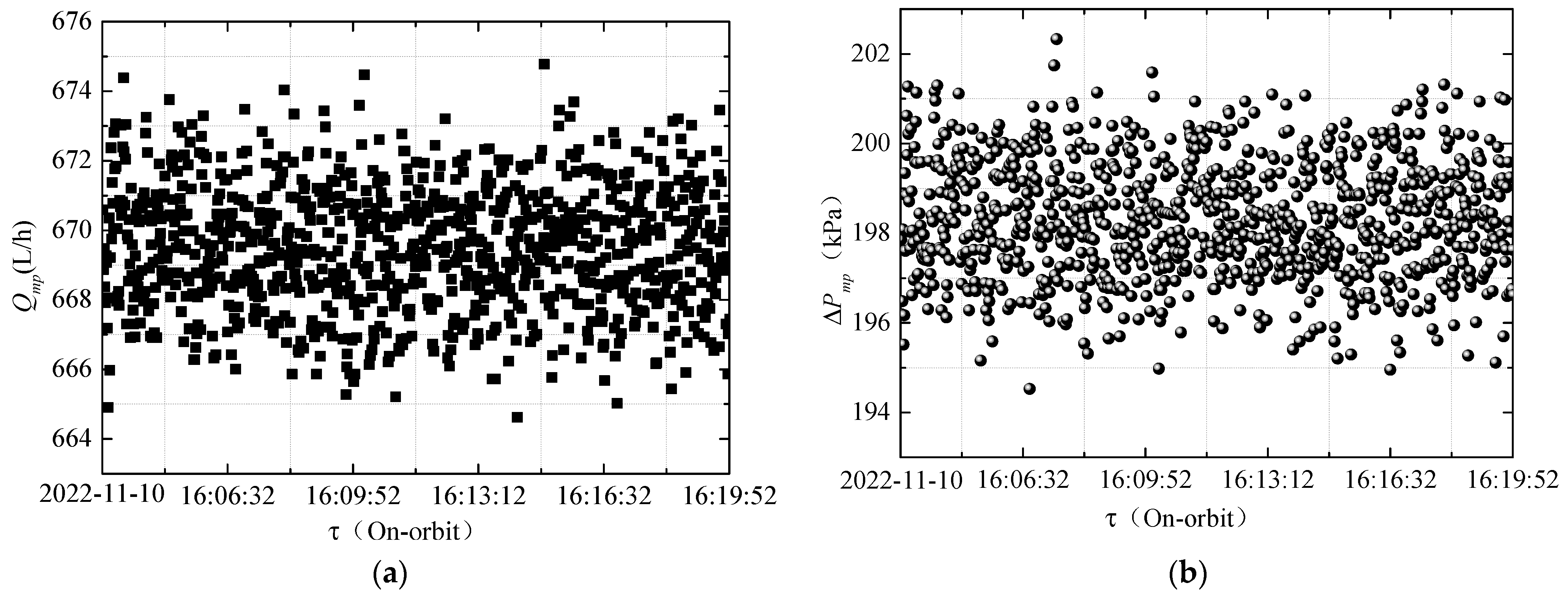
The working characteristics of the drive pump are the key to the thermal management system. The data and working characteristics of the drive pump under typical working conditions on orbit are analyzed. Figure 18a,b show the output flow rate and pressure difference time domain curves of the drive pump under typical working conditions.
Figure 18a shows that the flow rate of the drive pump varies from 666.8 L/h to 674.7 L/h; the fluctuation regarding the flow parameters is about 8 L/h. At the same time, the output pressure difference is between 195.6 and 201.1 kPa; the fluctuation is about 5.5 kPa. The output characteristics of the drive pump have good stability, and the maximum fluctuation is 2.81%.
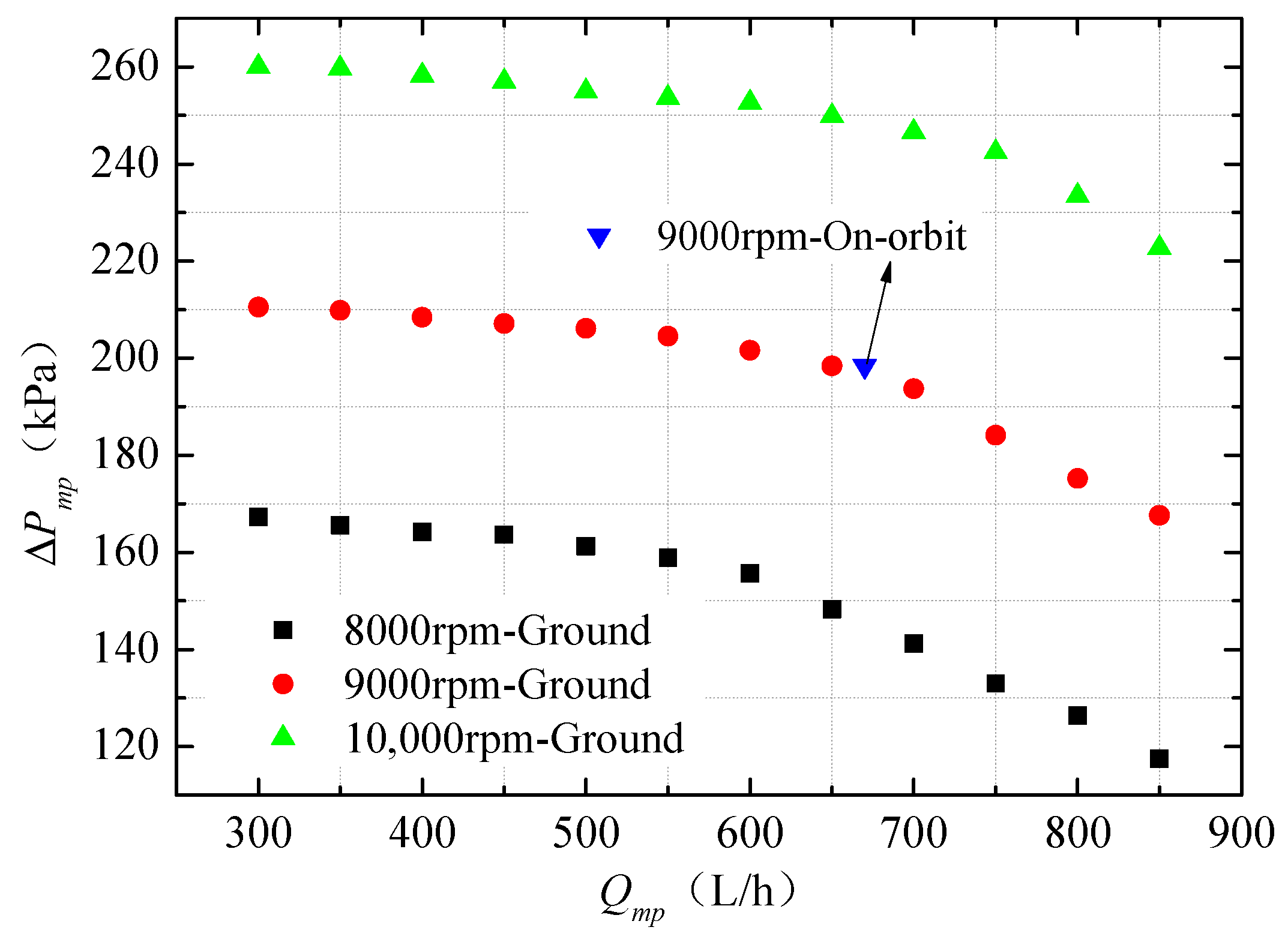
Figure 19 shows the output characteristic data of the drive pump under the specific operating conditions of the system. The pump speed is stable at 9060–9120 rpm; the fluctuation on orbit is 0.66%.
The ground test data for the drive pump are shown in Figure 19 and Table 3. Under the ground condition, the flow rate is 670.2–677.6 L/h and the output pressure difference is 193.2–196.2 kPa. Compared with the same working conditions on the ground, the average deviation of flow rate is 0.467% and the average deviation of pressure difference is 1.87%, showing good consistency.

5.4. Analysis of Two-Stage Fluid Network Regulation Effect

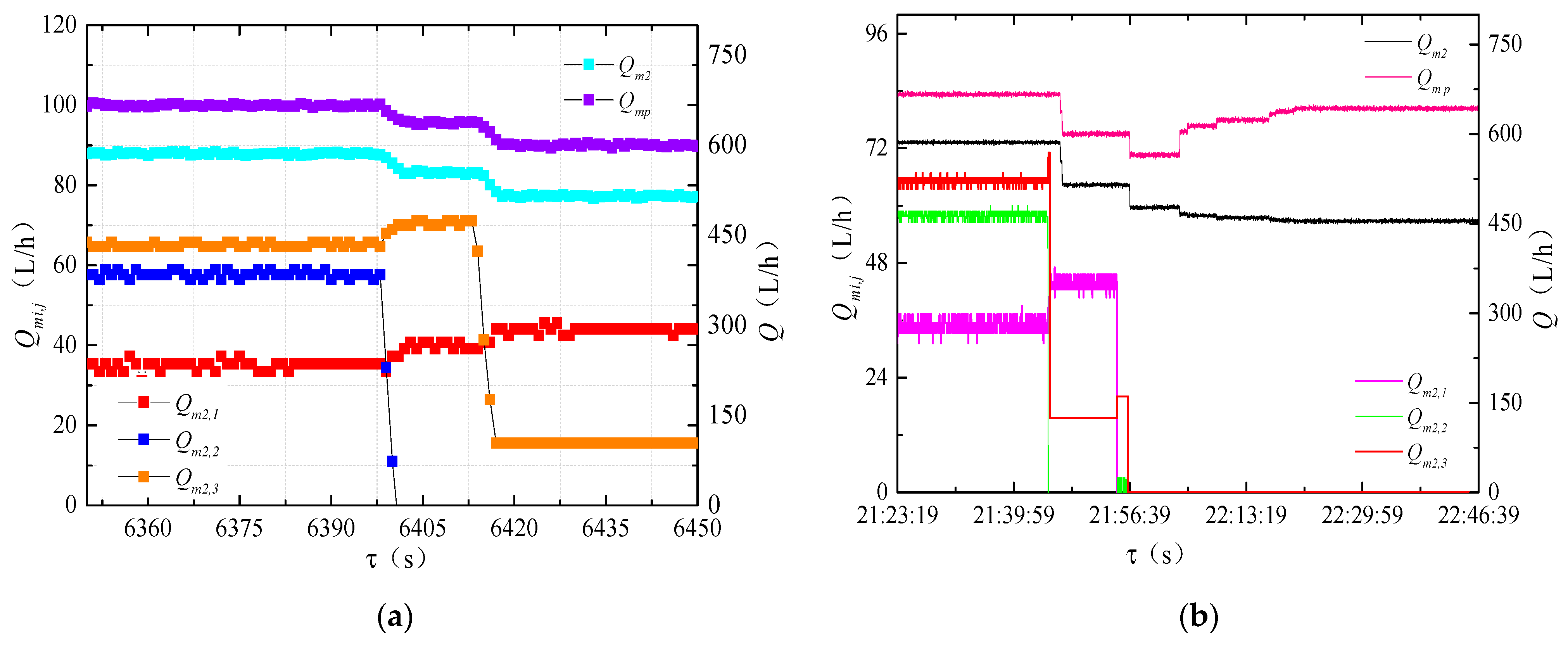
Dynamic adjustment is carried out according to the control scheme of the whole module in the process of payload experiment, and the thermal control system switches the mode by changing the opening degree and the switching state of the valve; Figure 20a,b show the dynamic response of the two-stage fluid network when the mode of payload rack 2 is switched.
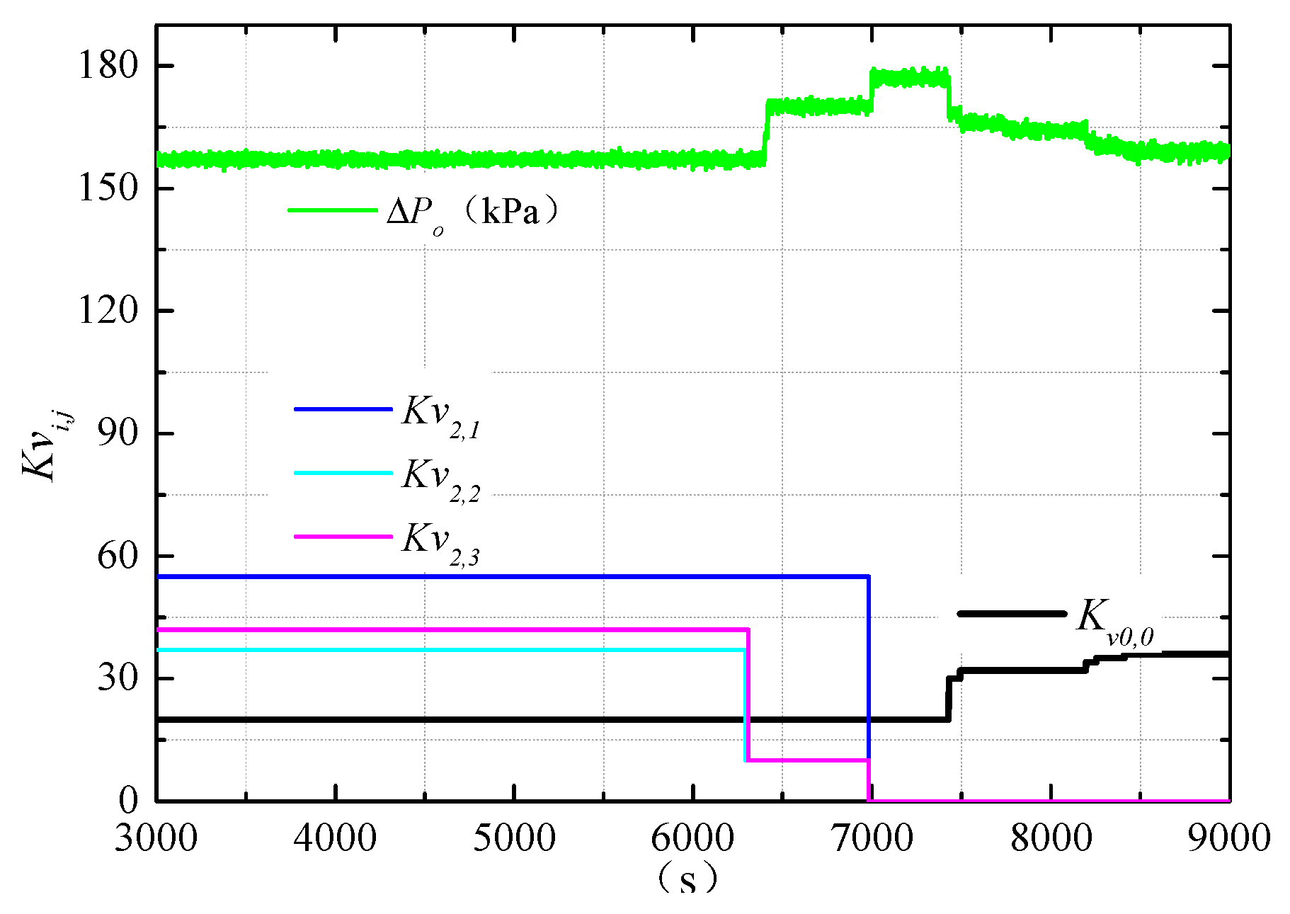
As shown in Figure 20a, during system mode switching, branch 2, branch 3 and branch 1 of payload rack 2 are successively adjusted to 10% from the set opening and then to 0%; the valve of branch 2 is adjusted from 37% to 10%, the flow rate reduced from 57.6 L/h to 0, the flow rate of branch 1 increased from 35.4 L/h to 40.8 L/h and the flow rate of branch 3 increased from 65.8 L/h to 70.1 L/h; at the same time, the total flow rate of the drive pump decreased from 665.8 L/h to 636.7 L/h; compared to pre-adjustment, the decrease is about 29.1 L/h.
Similarly, as shown in Figure 20b, in the process of reducing the opening of branch 3 from 44% to 10%, the flow rate of the third branch decreased by about 54.4 L/h; the flow rate of the drive pump decreased from 636.5 L/h to 600 L/h and decreased by about 36.5 L/h. When the first branch is adjusted from 55% to 0, the flow rate decreased by 44.2 L/h and the flow rate of the drive pump decreased by 35 L/h. After the three valves are adjusted, the total flow rate of the whole rack is adjusted from 156 L/h to 0, and the flow rate of the drive pump is reduced by about 100 L/h.
The pressure difference in pump bypass increased from 157 kPa to 175 kPa during the adjustment, increasing by about 18 kPa. In order to balance the pressure difference in TCB, the bypass valve is opened and the pressure difference is balanced. The bypass valve opening is adjusted from 20% to 36%; as shown in Figure 21, the bypass flow increased and the pressure difference in bypass recovered from 175 kPa to 160 kPa. The deviation is controlled at 3 kPa, and the control precision of pressure reaches 2%.

5.5. Analysis of Heat Transfer Characteristics On-Orbit

5.5.1. Heat Transfer Characteristics of TCB in Module

In order to verify the heat transfer characteristics of the thermal control system on orbit, the global temperature and hydraulic parameters were analyzed. In order to express the relationship between the heat transfer parameters and the heat transfer characteristics accurately, the characteristic parameters are defined here. According to the heat transfer characteristics of a certain rack i, the active heat transfer capacity is defined as follows:
ϕ i = c Q m i ρ Δ T i
where c is specific heat capacity of working medium (j/kg·K); Q m i is the total flow rate of the rack i (m3/s); ρ is the density of working medium (kg/m3); Δ T i is the temperature difference between inlet and outlet of rack i (K).
Therefore, we define the ratio of the heat power transferred through the fluid loop consumption to the whole rack’s heating power as the active heat transfer efficiency:
η i =   ϕ i φ i × 100 % = c Q m i ρ Δ T i φ i × 100 %
where φ i is the total heat power of rack i (W); ϕ i is the active heat transfer capacity (W).
Table 4 shows the power of each payload and the valve opening setting of the whole system. The power of payload rack 5 will change with the switch of working mode; the rest of the payloads maintain a constant working state.
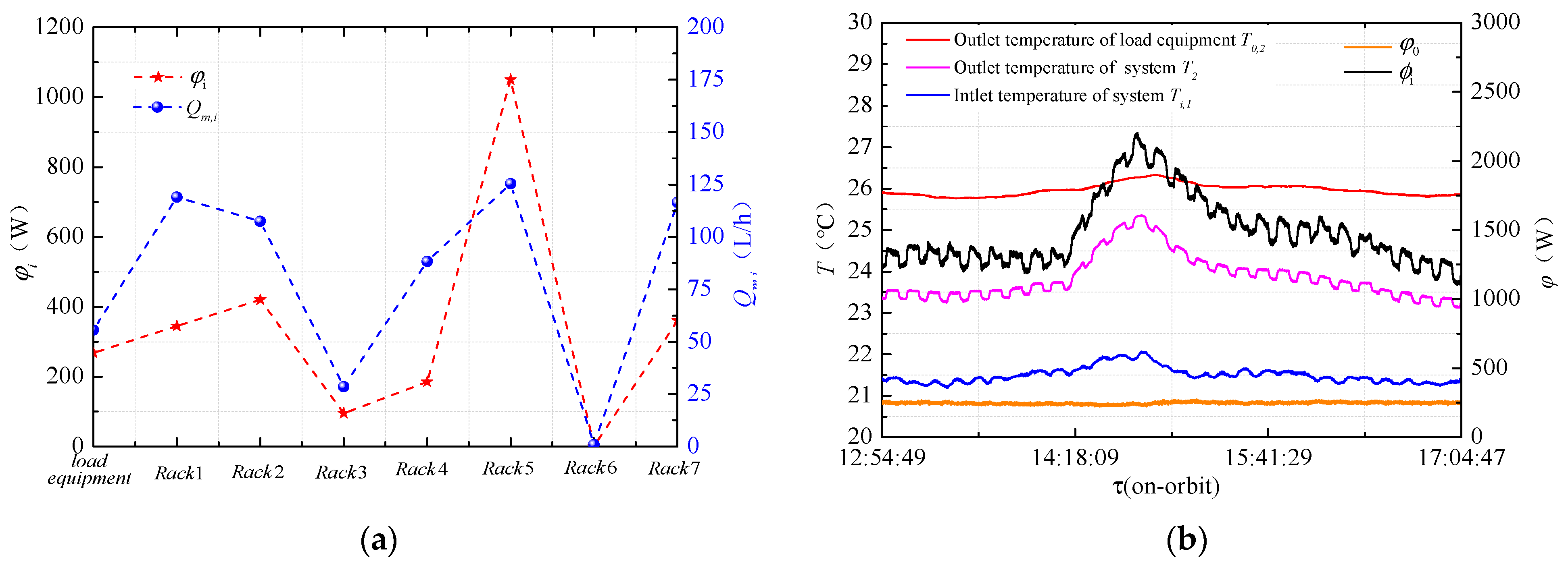
Figure 22a shows the relationship between total flow distribution and power of each rack under this condition. The flow rate of payload rack 1, payload rack 4 and payload rack 7 on orbit are all above 120 L/h. Payload rack 6 is not working, so its flow rate is 0. Branch 1 of payload rack 3 is in working condition with a flow distribution of 28.6 L/h. The flow rate is basically proportional to the power of the rack.
Figure 22b shows the global temperature changes during the system mode switching. When the power of the system is 1605 W, the liquid supply temperature of the system is about 21.3 °C and the average temperature of recirculation is 23.5 °C. The temperature difference between the inlet and outlet of the TCB can reach 2.2 °C. Combined with the total flow rate of the system and the property of working medium, the active heat dissipation of the system can be calculated to be 1518.6 W. The heat transfer efficiency of the system is 87%. When the power of the system increases to 2723 W, both the outlet temperature and the inlet temperature rise to a certain extent; the maximum temperature difference is 3.3 °C, the maximum heat transfer capacity of the fluid loop reaches 2280 W and the total heat exchange efficiency of the system reaches 83.7%.
Table 5 provides the flow distribution and steady state temperature distribution in the partial payload rack and the whole system. From the analysis of the data, we can draw a conclusion: the integrated thermal control management system can realize the temperature control and heat dissipation of all the scientific experimental loads in this module of CSS, the heat transfer efficiency of the second stage inside the rack is more than 80% and some racks are close to 90%. The overall heat transfer efficiency of the TCB system reaches more than 83%, which realizes the heat collection and dissipation of the loads in the module.

5.5.2. Analysis of Heat Transfer Characteristics inside Payload Rack

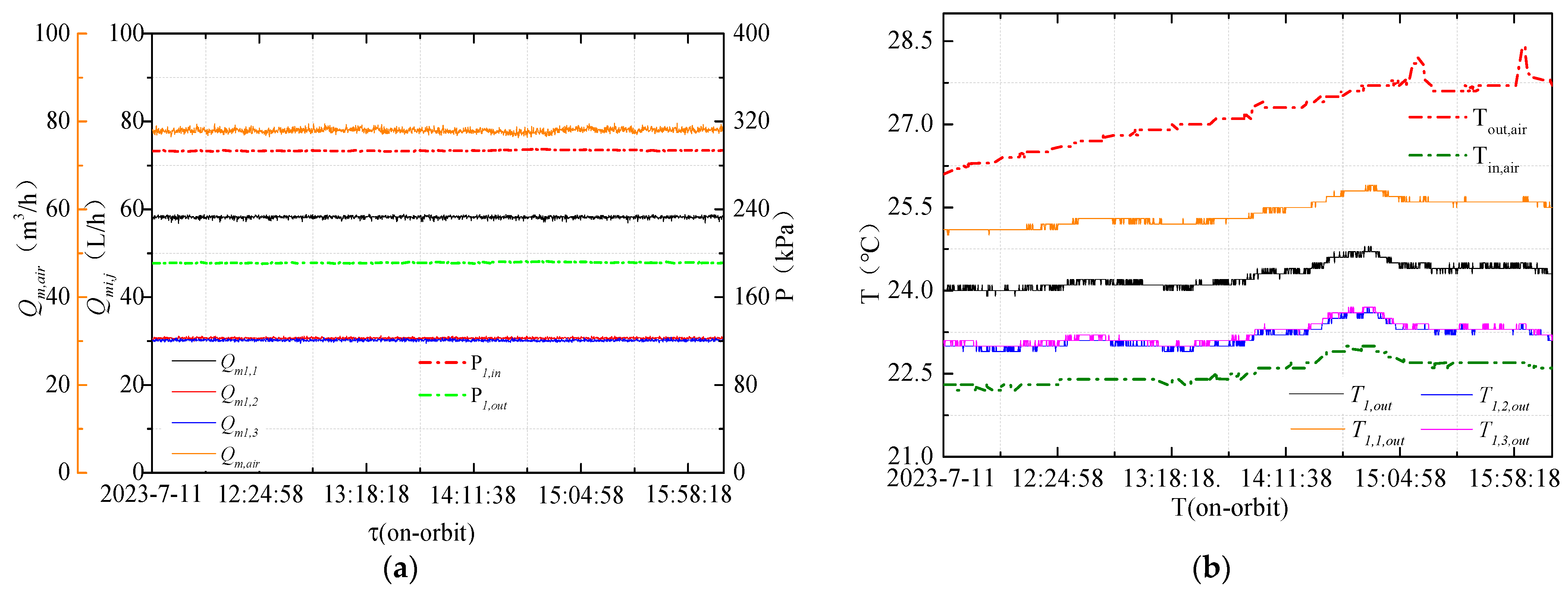
Payload rack 1 is a gas–liquid mixed heat exchange rack. During the period of on-orbit operation, the fan is opened for air-cooling heat exchange; the typical heat exchange parameters and hydraulic parameters in the working process of the rack are as shown in Figure 23. In Figure 23a, the working pressure difference in the payload rack 1 is 102.1 kPa. During operation on-orbit, the flow rate values of the three branches of the rack are 58.2 L/h, 30.6 L/h and 30.2 L/h. The flow rate of the fan is 77.5 m3/h. The transient temperature responses are given in Figure 23b, the temperature of the working medium provided by the thermal control bus is 22.4 °C.
The results of the analysis are shown in Figure 24; the active heat exchange capacity of the whole rack reaches 272.7 W, and the maximum air-cooled heat transfer capacity of the secondary thermal control system inside the rack is 160 W; the ratio of air-cooled heat transfer is 58.7%, and the active heat transfer efficiency of the whole rack is 85.96%.

6. Conclusions

A bus-type two-stage thermal control system based on fluid loop is proposed for the thermal management of large-scale and diversified scientific experimental loads in the payload lab module of China Space Station. The working principle of the thermal management system and the internal design of the key units are introduced in this paper. A kind of control method for the two-stage thermal control system based on “pump bypass” and the “valve resistance ratio” is put forward. The performance of the thermal control system in CSS is tested and verified. The key parameters on orbit are compared to those on ground. Through the on-orbit test, a large number of data of typical working conditions are obtained.
After the design of the thermal control system and the theoretical analysis of the control method, it is concluded that:
  • The two-stage thermal management system based on single-phase fluid circuit and parallel bus can effectively solve the system heat dissipation and diversified thermal control requirements of the cluster space payloads.
  • Based on the pump bypass structure of the system, the proper increase in working pressure difference in TCB is conducive to improve the flow rate control capacity of the downstream rack, and also to reduce the work flow rate of the circulating pump under the same flow rate output capacity of TCB, which will reduce system power consumption.
  • A reasonable valve resistance ratio is the key to control ability in the rack. Too large a valve resistance ratio will lead to an increase in resource costs under the same flow rate demand, and too small a valve resistance ratio will lead to insufficient control and compensation ability.
Taking the above-mentioned thermal control system applied in module 2 of CSS as an example, after test verification on orbit, the following conclusions can be drawn regarding the design frame of the module and the working parameters of the pump valve:
The effectively constructed thermal control system supports the thermal management of the payloads in module 2. The pressure control accuracy on orbit is up to 2%. The active heat exchange efficiency of the thermal control system in the rack is more than 80% and may reach 90%. The heat exchange efficiency of the TCB is more than 83%. Compared with the ground data, the parameters on orbit have good consistency. So far, the thermal management systems of the three modules in CSS are working in good condition. The research in this paper also plays an active role in promoting the development of space thermal control technology and thermal management in China.

Author Contributions

Conceptualization, D.G., Q.S. and J.X.; methodology, D.G. and J.C.; validation, D.G. and Q.S.; formal analysis, D.G.; resources, D.G. and W.W.; data curation, D.G. and J.C.; writing—original draft preparation, D.G. and Z.W.; writing—review and editing, M.X., X.X. and W.W.; visualization, D.G. and Z.W.; supervision, M.X., X.X. and K.W.; project administration, K.W.; funding acquisition, K.W. All authors have read and agreed to the published version of the manuscript.

Funding

This study is supported by a research project undertaken by Technology and Engineering Center for Space Utilization, Chanese Academy of Science, project name: Space Station Applied Fluid Loop System, project number: Y3140621PN.

Institutional Review Board Statement

Not applicable.

Informed Consent Statement

Not applicable.

Data Availability Statement

The data presented in this study are available on request from the corresponding author. The data are not publicly available due to privacy.

Acknowledgments

This work was supported by Technology and Engineering Center for Space Utilization, Chinese Academy of Science. All flight products were developed by the scientific research institute.

Conflicts of Interest

The authors declare no conflicts of interest.

References

  1. Yu, X.G.; Meng, F.K.; Han, H.Y. The development of manned spacecraft thermal control technology in our country. Spacecr. Eng. 2022, 31, 156–165. [Google Scholar] [CrossRef]
  2. Miao, J.Y.; Zhong, Q. Thermal Control Technology of Spacecraft, 1st ed.; Beijing Institute of Technology Press: Beijing, China, 2018. [Google Scholar]
  3. Hou, Z.Q.; Hu, J.G. Thermal Control Technology of Spacecraft-Principle and Application, 3rd ed.; China Science and Technology Press: Beijing, China, 2007. [Google Scholar]
  4. Min, G.R.; Guo, S. Spacecraft Thermal Control, 2nd ed.; Science Press: Beijing, China, 1998. [Google Scholar]
  5. Ning, X.W.; Li, J.D.; Wang, Y.Y.; Jiang, F. Review on construction of new spacecraft thermal control system in China. Acta Aeronaut. Astronaut. Sin. 2019, 40, 022874. [Google Scholar] [CrossRef]
  6. Ning, X.W.; Xu, K.; Wang, Y.Y.; Jiang, F. Chang’e-5 complex of lander and ascent vehicle lightweight pumped fluid loop thermal bus: Design and implementation. J. Aeronaut. 2022, 43, 126292. [Google Scholar] [CrossRef]
  7. Birur, G.; Bhandari, P. Mars Pathfinder Active Thermal Control System: Ground and Flight Performance of a Mechanically Pumped Loop. In Proceedings of the AIAA Thermophysics Conference, Atlanta, GA, USA, 23–25 June 1997. [Google Scholar]
  8. Guo, Z.Y.; Liang, X.G.; Zhang, X.R. Space Station heat management. Chin. Sci. Bull. 2001, 23, 1403–1408. [Google Scholar]
  9. Li, M.H.; Ren, J.X.; Liang, X.G. Application of heat pump integrated with waste heat recycle in thermal management system of space station. Acta Energiae Solaris Sin. 2002, 23, 181–186. [Google Scholar]
  10. Zhou, Z.X.; Huang, J.Y.; Zhang, H.X.; Zhao, L. Development and prospect of spacecraft thermal control technology in China. Spacecr. Eng. 2023, 32, 1–9. [Google Scholar] [CrossRef]
  11. Yan, Y. Development process and follow-up planning of International Space Station. Space Int. 2021, 4, 16–24. [Google Scholar]
  12. Wieland, P.O.; Roman, M.C. Living Together in Space: The International Space Station Internal Active Thermal Control System Issues and Solutions-Sustaining Engineering Activities at the Marshall Space Flight Center from 1998 to 2005; Marshall Space Flight Center: Huntsville, AL, USA, 2007. [Google Scholar]
  13. De Palo, S.; Klingberg, T.; Persson, J. Control Stability Analysis Applied to Columbus ATCS; SAE Technical Paper; SAE: Warrendale, PA, USA, 2009. [Google Scholar]
  14. Thurman, R.L. Active Thermal Control of Parallel Heat Loads on Space Station US Laboratory Module; SAE Technical Paper; SAE: Warrendale, PA, USA, 1994. [Google Scholar]
  15. Sleiman, A.Y. Active Thermal Control System Kit for International Standard Payload Rack. In Proceedings of the 25th International Conference on Environmental Systems, San Diego, CA, USA, 10–13 July 1995. [Google Scholar] [CrossRef]
  16. Vaccaneo, P.; Gottero, M. The Thermal Environmental Control (TEC) of the Fluid Science Laboratory (FSL): A Combined (Water/Air) Thermal Design Solution for a Columbus Active Rack. In Proceedings of the 31st International Conferenceon Environmental Systems, Orlando, Florida, USA, 9–12 July 2001. [Google Scholar] [CrossRef]
  17. Julian, D.; Kohlhase, A.O.; Porth, N. An advanced columbus thermal and environmental control system. SpaceOps 2012, 2012, 1292285. [Google Scholar] [CrossRef]
  18. Wang, X.; Zhang, Q.; Wang, W. System characteristics and prospect of China Space Station. Spacecr. Eng. 2022, 31, 26–39. [Google Scholar] [CrossRef]
  19. Yang, R. The Construction Road of China Space Station. PLA Daily, 28 October 2022. [Google Scholar] [CrossRef]
  20. Chen, B. The basic configuration of the “T” shape of the Chinese Space Station has been assembled On-orbit. Satell. Appl. 2022, 11, 70. [Google Scholar]
  21. Gu, Y.D. The China Space Station: A new opportunity for space science. Natl. Sci. Rev. 2022, 9, nwab219. [Google Scholar] [CrossRef] [PubMed]
  22. Fluid Physics, Two-Phase Systems, High-Precision Time-Frequency. What’s in the Science Locker? Nine Scientists Are Hard-Core Science. Available online: https://export.shobserver.com/baijiahao/html/544617.html (accessed on 17 September 2022).
  23. The Lab Module of “Wen Tian”. Available online: https://baike.so.com/doc/30100326-31725326.html (accessed on 31 October 2022).
  24. Let’s Visit the New Classroom and Explain the 4 Racks in the Lab Module of “Wen Tian”. Available online: https://china.zjol.com.cn/gnxw/202210/t20221012_24916388.shtml (accessed on 12 October 2022).
  25. Yan, J. Discussion about Bus-Mechanical Hydraulic Circuit. Met. Mater. Metall. Eng. 2008, 36, 25–27. [Google Scholar]
  26. Qu, S.L.; Wu, Y.B.; Zhao, H.B. Study on flow regulation characteristics of valve in water distribution system. Fluid Mach. 2003, 31, 16–18. [Google Scholar]
  27. Chen, S. Analysis and optimization of valve flow characteristics. Electromech. Inf. 2018, 540, 88–89. [Google Scholar]
Figure 1. Distribution of the payloads in every module of CSS.
Applsci 14 02938 g001
Figure 3. Topological structure of integrated thermal management system.
Applsci 14 02938 g003
Figure 4. Bus-type load rack thermal management system product architecture.
Applsci 14 02938 g004
Figure 5. Working principle diagram of TCB and drive unit.
Applsci 14 02938 g005
Figure 6. Main structure of the fluid drive device.
Applsci 14 02938 g006
Figure 7. Principle of second-stage thermal control system in different racks: (a) primary liquid-cooled rack; (b) gas–liquid mixed cooled rack; (c) secondary circuit liquid-cooled rack.
Applsci 14 02938 g007
Figure 8. Design principle of liquid-cooled thermal control terminal.
Applsci 14 02938 g008
Figure 9. Design principle of gas–liquid mixed thermal control terminal.
Applsci 14 02938 g009
Figure 10. Design principle of secondary circuit thermal control terminal.
Applsci 14 02938 g010
Figure 11. The basic structure and characteristics of the circuit based on pump bypass: (a) pump bypass model; (b) adjusting characteristic curves.
Applsci 14 02938 g011
Figure 12. The pressure difference-flow rate characteristics of drive pump and TCB.
Applsci 14 02938 g012
Figure 13. The relationship between the characteristics of bypass valve and the control range of TCB: (a) the relationship between Q mo , min ~ Q mv , max ; (b) the relationship between Δ P o ~ Q mv , max .
Applsci 14 02938 g013
Figure 14. Simplified flow model inside the payload rack.
Applsci 14 02938 g014
Figure 15. Ideal flow characteristics of valves.
Applsci 14 02938 g015
Figure 16. Flow regulation characteristics of different valves (S = 0.5): (a) linear type; (b) logarithmic type; (c) quick-open type.
Applsci 14 02938 g016
Figure 17. Working principle of integrated thermal control system in module.
Applsci 14 02938 g017
Figure 18. On-orbit working characteristics and ground data comparison of drive pump: (a) flow rate of pump on orbit; (b) pressure difference in pump on orbit.
Applsci 14 02938 g018
Figure 19. On-orbit working parameters and ground characteristic curves of the drive pump.
Applsci 14 02938 g019
Figure 20. Response of flow parameters during rack adjustment process on orbit: (a) the parameter changes in the rack; (b) the parameter changes in the system.
Applsci 14 02938 g020
Figure 21. Bypass pressure difference response during rack on-orbit adjustment process.
Applsci 14 02938 g021
Figure 22. Hydraulic and heat transfer characteristics of thermal control system: (a) operating parameters of each rack on orbit; (b) system temperature and heat transfer characteristic curves.
Applsci 14 02938 g022
Figure 23. Heat transfer characteristic curve of payload rack 1 on-orbit: (a) Hydraulic parameters; (b) Temperature characteristic.
Applsci 14 02938 g023
Figure 24. Result of heat exchange data analysis of payload rack 1.
Applsci 14 02938 g024
Table 1. Heat source characteristics and temperature control requirements inside the rack.
NameDescriptionType 1 *Type 2 *Type 3 *
Payload layoutLayout FeatureCentralized and regular layoutLarge enclosed space, small-size discrete distributionSpecial-shaped layout, personalized layout
Heat consumptionIndicators (W)<300 W300–1000 W1000–2300 W
Tem StabilityIndicator (°C/h)±5 °C/h±0.5–1 °C/hmK/h
ObjectiveElectronics equipmentOptical loadBasic physical load
Tem levelIndicators (°C)−10–45 °C0–10 °C4 °C, −20 °C, −80 °C
ObjectiveElectronics equipmentLow-temperature loadBiological sample
Tem Uniformity /No special needs≯5 °C≯10 mK
Mode of operation/ContinuouslyDiscontinuousMonorail time-sharing work
Other constraints/Contact heat transferNon-contact heat transferHeat transfer without disturbance
* The longitudinal load characteristics of the rack do not match; all kinds of load characteristics are cross-distributed.
Table 2. Index parameters and heat sink boundary of thermal management system.
Indicator TypeKey IndicatorsParameter
Performance indicatorsFlow rate of TCB (L/h)≮600
Operating pressure (kPa)150–180
Pressure difference in TCB (kPa)≮75
Temperature (°C)19–26
Flow rate of load equipment branch (L/h)(60 ± 10)
Flow rate of payload rack (L/h)30–170
Boundary
conditions
Temperature of heat exchanger (°C)16–22
Flow rate of heat exchanger (L/h)500 ± 50
Air temperature inside module (°C)19–26 °C
Table 3. On-orbit working parameters and ground data of the drive pump.
Data SourcesFlow Rate (L/h)Pressure Difference (kPa)Pump Speed (rpm)
Ground670.2–677.6193.2–196.29060–9120
On-orbit666.8–674.7195.6–201.19060–9120
Mean Deviation0.467%1.87%0
Table 4. Typical operating conditions and parameters on orbit.
NumberName of the Payload Power   φ i (W)Valve Opening
1Load equipment 1–3268 K v 0 = 30%
2Payload rack 1345 K v 1 , 1 = 35% K v 1 , 2 = 30% K v 1 , 3 = 30%
3Payload rack 2420 K v 2 , 1 = 32% K v 2 , 2 = 5% 1  K v 2 , 3 = 47%
4Payload rack 395 K v 3 , 1 = 24% K v 3 , 2 = 5% 1 K v 3 , 3 = 5%
5Payload rack 4185 K v 4 , 1 = 28% K v 4 , 2 = 5% 1  K v 4 , 3 = 36%
6Payload rack 572–1050 W K v 5 , 1 = 38% K v 5 , 2 = 44% K v 5 , 3 = 5%
7Payload rack 60 K v 6 , 1 = 5% 1  K v 6 , 2 = 5% 1
8Payload rack 7360 K v 7 , 1 = 22% K v 7 , 2 = 40%
9Total of the module1745–2723/
1 When the valve opening is 5%, this represents that the load of the branch is not working.
Table 5. On-orbit data of the integrated thermal management system in the module.
Name of PayloadObject K v i , j (%) φ i (W) Δ T i (°C) ϕ i (W) η i
Payload rack 1Branch 135 3.5211.51
Branch 2 30 1.341.30
Total of rack 3452.4296.55 85.96%
Payload rack 2Branch 1 32 1.555.14
Branch 25 2.20.00
Total of rack 4203.3368.35 87.70%
Payload rack 4Branch 1 28 2.993.95
Branch 2 5 2.20.00
Total of rack 1851.8165.03 89.21%
Payload rack 5Branch 1 38 2.7165.41
Branch 2 44 11.6799.77
Total of rack 10507911.45 86.80%
Payload rack 7Branch 1 22 1.882.80
Branch 240 2.8209.62
Total of rack 3602.5302.16 83.93%
The whole module 27233.32279.99 83.73%
Disclaimer/Publisher’s Note: The statements, opinions and data contained in all publications are solely those of the individual author(s) and contributor(s) and not of MDPI and/or the editor(s). MDPI and/or the editor(s) disclaim responsibility for any injury to people or property resulting from any ideas, methods, instructions or products referred to in the content.