Abstract
Compositions of fine-grained concrete mixtures that provide the minimum required strength values in 1 day (7.5 MPa) have been developed. A comparison was made of the test results of the properties of samples printed on a 3D printer with samples made according to the same recipes on a vibrating platform. A laboratory printer was designed and constructed to study the properties of extruded mixtures. The method was also proposed for measuring concrete mixes’ structural strength. Analysis of experimental data allowed the establishment of the features of the influence of the mineral additives and slag–alkaline binders for a comparison of basic physical and mechanical properties of concretes for 3D printing. It has been experimentally shown that possible undercompaction of the fine-grained mixtures formed on a 3D printer and decrease of properties are compensated by the introduction of hardening activator and superplasticizer additives. The novelty of this work lies in determining the comparative effect of various products of technogenic origin on the properties of mixtures for 3D printing.
1. Introduction
The development of new technologies in the construction industry in the near future will make it possible to fundamentally change the views and approaches to the traditional methods of erecting buildings and structures, as well as solve a number of environmental and economic problems. The most urgent problems include reducing the cost and impact on the environment and increasing the speed of construction without losing quality. A rational solution to these problems is using the additive method of erecting buildings and structures. This technology involves using a special 3D printer to apply a plastic concrete mixture layer by layer and building the walls by extrusion. The accuracy, speed, and ability of the 3D printer to build three-dimensional shapes of considerable complexity make this technology increasingly popular [1,2,3].
Fine-grained concretes based on Portland cement have become the most widely used for 3D printing in construction [4,5,6]. They can be attributed to the so-called digital concretes, which mean materials obtained using machines with numerical software control. As a rule, for extrusion molding, mixtures should contain more binder than ordinary concrete mixtures with similar mechanical characteristics [7,8,9,10].
Composites with lower cement consumption, high mechanical characteristics, and good durability can be obtained using active mineral additives [11,12]. In these composites, additives can play the role of cementing, pozzolanic, or filling materials [13,14].
Usually, such active mineral additives include blast furnace slag, fly ash, and microsilica, which are often used in energy-efficient and digital concretes [15,16,17,18,19,20,21].
Limestone as a filler in concrete, consisting mainly of calcium carbonate, causes the formation of monohydrocarboaluminates and hexagonal calcium hydroaluminates [22]. This effect makes it possible to stabilize ettringite by increasing the volume of hydrates and reducing porosity.
Inert materials, such as powders of granite, basalt, and other rocks [23,24], act as nuclei of crystallization that fill the voids in the microstructure of the cement dough and physically stimulate the hydration of cement in the first few days of hardening [14,25].
Cementless or low-cement materials (geopolymers) are promising synthesized compounds based on crystalline aluminosilicate materials and alkaline-activated binders. Hardened geopolymers have a different chemical composition than Portland cement stone and fundamentally differ in structure [26,27].
According to [28], Table 1 shows the corresponding characteristics of typical “standard” concretes compared to some digital concretes, divided into one-component (1K) and two-component (2K) systems. The cement content is much higher for digital concretes, unless they contain significant cement replacement materials.

Table 1.
Comparative characteristics of standard and digital concrete.
The development of digital concrete involves increased early strength, including the strength achieved by the previous layer of the concrete mix, before laying the next layer (structural strength).
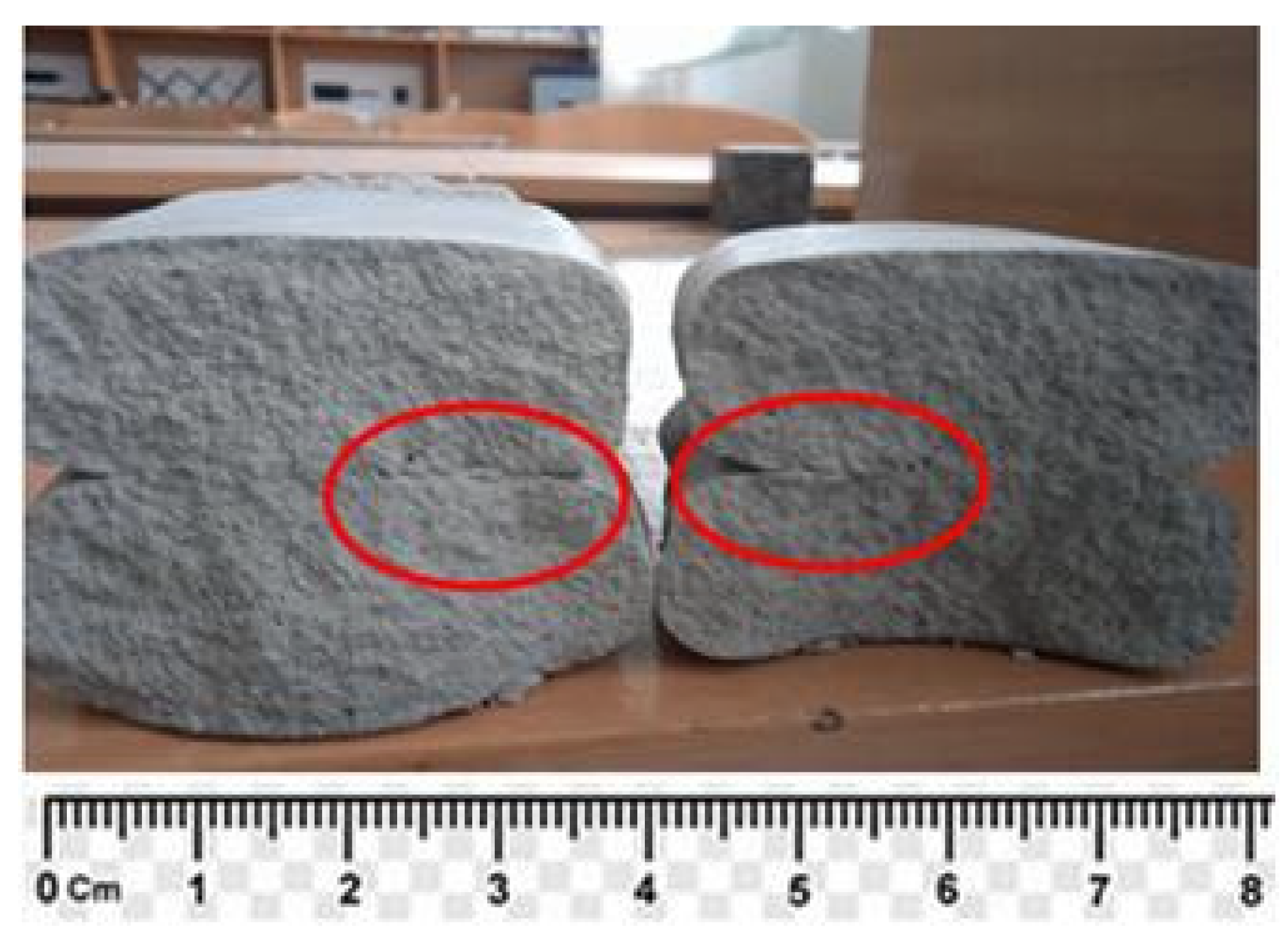
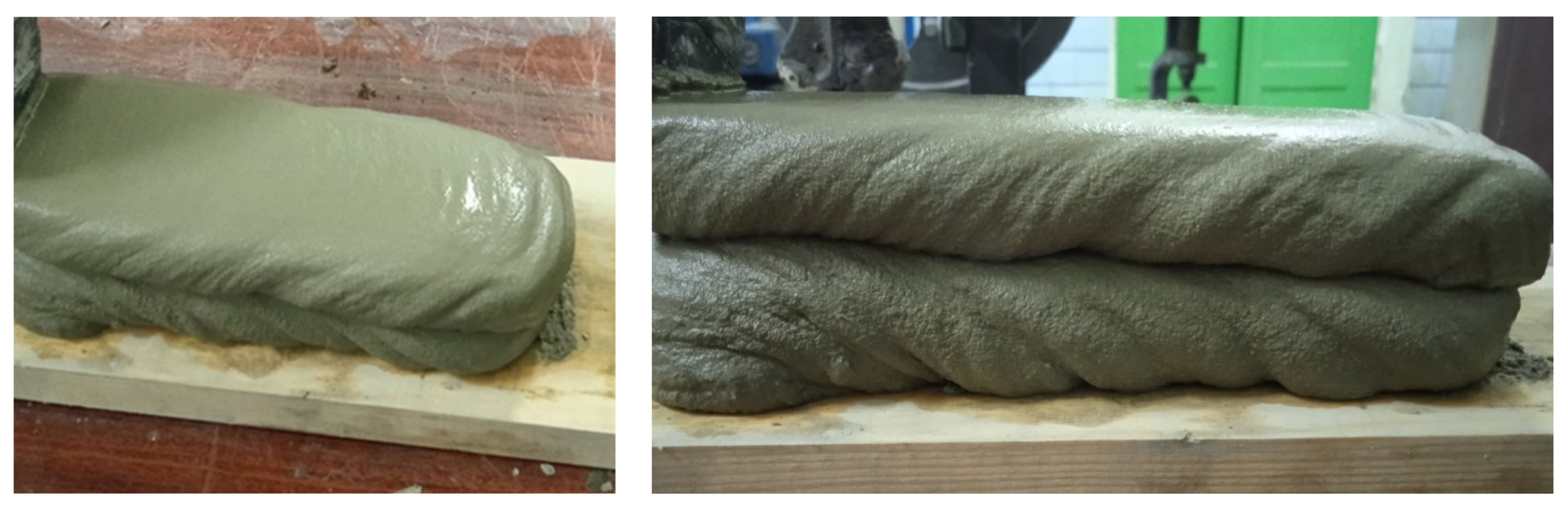
An essential factor to consider when designing the composition of digital concrete is its durability. In this regard, it should be considered that the dominant technology of extrusion printing can lead to uneven application of layers, the formation of defects, and, as a result, a decrease in adhesion between them (Figure 1). The time interval contour length and printing speed also affect the quality of the layers [37]. The reduction of adhesion between the layers is no less substantial than the strength under compression and bending from the standpoint of durability, while the formed defects create ways for the accelerated penetration of water and aggressive agents, which in turn affects the waterproofness and frost resistance of the multilayer structure. It should be noted that with an increased content of cement paste, there is a greater risk of cracking and shrinkage.

Figure 1.
Photograph showing the defects when applying layers. Bonding zone—in red.
Thus, the analysis of the current state of 3D printing technology in construction allows to state that there are prerequisites for the effective use of industrial waste as mineral additives with the achievement of the optimal mixture composition, which provides the necessary standardized extrusion and mechanical characteristics of digital concrete.
Data from the Status of Construction Report [38] indicate that the construction sector is responsible for 35% of global energy consumption, almost 38% of carbon dioxide emissions, and almost 1/3rd of waste production. These figures confirm the need to transform the construction industry to reduce its environmental impact. The possibility of digitizing production, which, combined with the use of sustainable building materials incorporating recycled raw materials, has the potential for the conventional construction sector to undergo change and modernization towards lower greenhouse gas emissions and waste.
The purpose of this work was to conduct a comparative study of the impact of the most common industrial wastes on the formability (extrudability) and mechanical characteristics of concretes suitable for 3D printing.
2. Materials and Methods
To obtain materials investigated as mineral additives, we used Portland cement (CEM I 42.5 R (EN 197-1)), blast furnace granulated slag (GBFS), fly ash (FA), limestone powder (LP), and granite aspiration dust (GD).
The mineralogical composition of the clinker of used cement was as follows: C3S–57.10%; C2S–21.27%; C3A–6.87%; C4AF–12.19% (EN 196-2). The specific surface area of Portland cement was S = 330–350 m2/kg (EN 196-6). The chemical composition of Portland cement and mineral additives is given in Table 2.
Table 2.
Chemical composition of Portland cement clinker * and mineral additives.
Blast furnace granulated slag had a glass phase content of 75–80%, its specific surface S = 320–350 m2/kg, density—2.9 g/cm3, bulk density—1340 kg/m3.
Granite aspiration dust used with a specific surface S = 230–250 m2/kg, density—2.79 g/cm3, bulk density—980 kg/m3.
Fly ash of type II category B with the size of particles passing through a sieve of 45 μm no more than 25% (class 2) (EN 450-1:2012) was used. The specific surface of ash is 250–280 m2/kg.
Limestone powder had a specific surface S = 450–480 m2/kg;
In addition, the effectiveness of activated slag in the composition of concretes based on slag–alkaline binders was studied, the composition of which was adopted based on the studies of a number of authors [27] and included GBFS, CEM I 42.5 R, and NaOH (85%, 10%, and 5% of the mixture, respectively).
Superplasticizer of the polycarboxyl type, with a water-reducing effect of 30% (EN 934-2), was used.
Sodium hydroxide (NaOH) was used as a hardening activator.
Quartz sand with a fineness modulus of 2.1, and a content of dusty and clay particles up to 1.0% (EN 12620) was used as an aggregate.
In order to study the properties of extruded mixtures, a laboratory printer was designed and constructed, as shown in Figure 2. The head of the nozzle was a rectangle with dimensions of 20 × 40 mm.
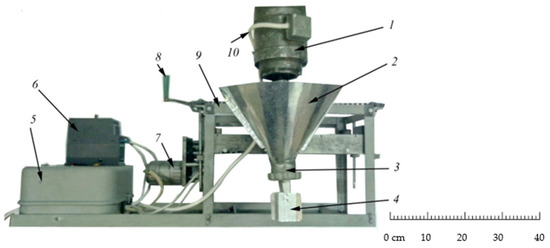
Figure 2.
Photograph showing the laboratory 3D printer: 1—electric motor of the extruder; 2—hopper of building mixture; 3—auger; 4—replaceable nozzle; 5—control panel; 6—frequency converter of electricity; 7—reverse motor moving the extruder in the horizontal direction; 8—manual drive moving the extruder in the vertical direction; 9—frame; 10—power cable of electric motors.
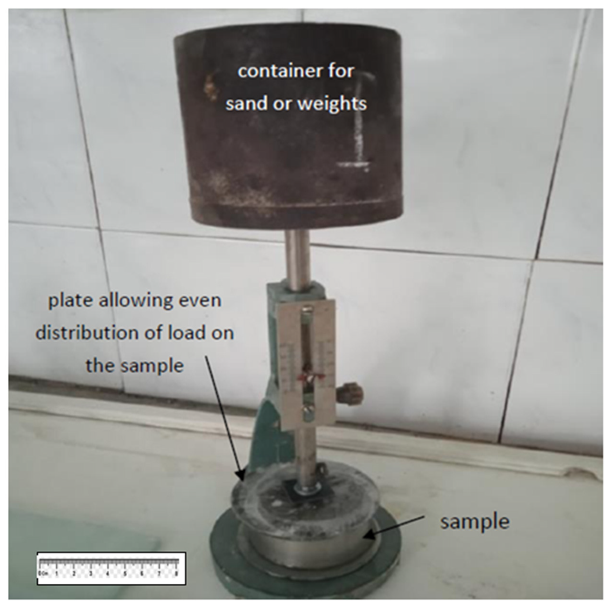
The main task in the study of concrete mixtures suitable for a 3D printer is to ensure their necessary shape during extrusion from the printer head with the achievement of the specified strength of the layers (structural strength), as well as the adhesive strength between the layers of extruded concrete without the formation of cracks and other defects [4,37]. To determine the structural strength, a method is proposed that allows measuring the ultimate load on a sample of an extruded layer of concrete, at which it begins to deform (Figure 3 and Figure 4).
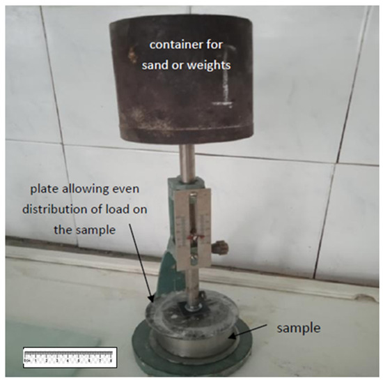
Figure 3.
Photograph showing the device for determining the structural strength.
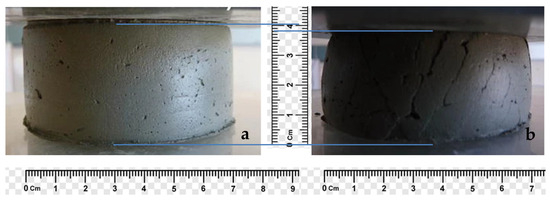
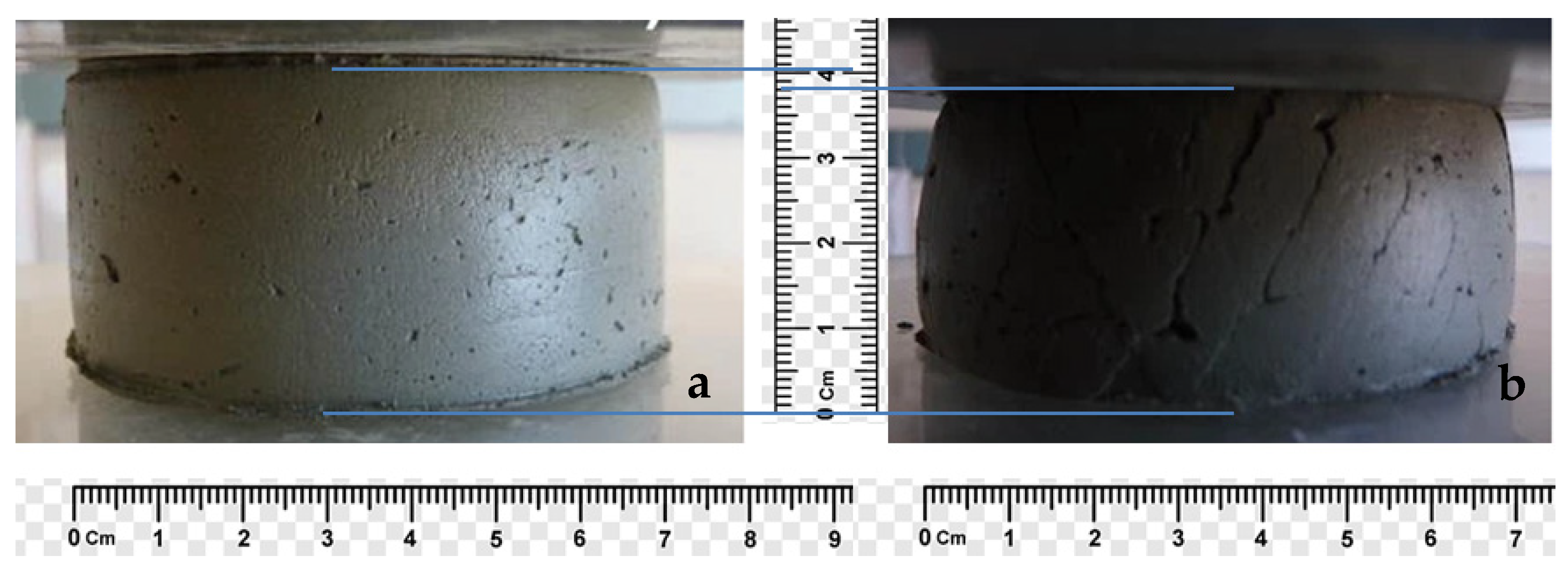
Figure 4.
An example of determining the structural strength of extruded concrete: (a) the sample withstands the load (structural strength is provided) structural strength > 4500 Pa; (b) the sample is destroyed.
The workability of concrete mixtures was determined by cone spreading. The bending, tensile strength at splitting, and compression were determined according to EN 196-1 at 1, 3, and 28 days. The adhesion strength of layers on samples formed by a laboratory 3D printer was determined by measuring the corresponding splitting stress.
The initial setting time of the mixtures was determined according to EN 196-3 from the moment of mixing to the beginning of hardening, at which point further molding using a 3D printer becomes impossible.
The average density of the samples was determined according to EN 1015-11.
3. Results and Discussion
The composition of the mixtures (Table 3) was selected under the condition of using the maximum content of mineral additives, which provides the minimum necessary structural strength after 20 min of mixing and compressive strength at the age of 1 day, by performing several tests, the results of which are shown in Table 4 [4,12,39]. The results in Table 4 represent the average of three trials.
Table 3.
Investigated compositions of mixtures for a 3D printer.
Table 4.
Properties of investigated compositions of mixtures suitable for 3D printing.
The minimum structural strength of 4500 Pa is calculated on the condition that the structure can withstand nine layers of 25 mm height applied for 20 min.
The minimum required compressive strength of the multilayer structure at 1 day is 7.5 MPa. Such strength is inherent in several wall materials based on ceramic bricks and aerated concrete [4,37].
During further research, for comparison with 3D printing, after vibration compaction, beam samples measuring 160 mm × 40 mm × 40 mm were made on a laboratory vibration platform. For the received samples, the average density, bending, and splitting strength as well as compressive strength were determined. In parallel with this, samples were formed on a laboratory 3D printer (Figure 5), which were also subject to testing. The water content was selected to achieve high-quality formation of the mixture from the printer nozzle without the formation of inflows, delaminations, and breaks. The obtained results are listed in Table 5 and Table 6.
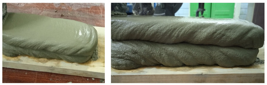
Figure 5.
Photograph showing the test samples were made using a 3D printer.
Table 5.
Results of the study of the influence of the type of mineral additive on the properties of concrete mixtures for a 3D printer.
Table 6.
Results of the study of the properties of concrete obtained by a 3D printer and vibration.
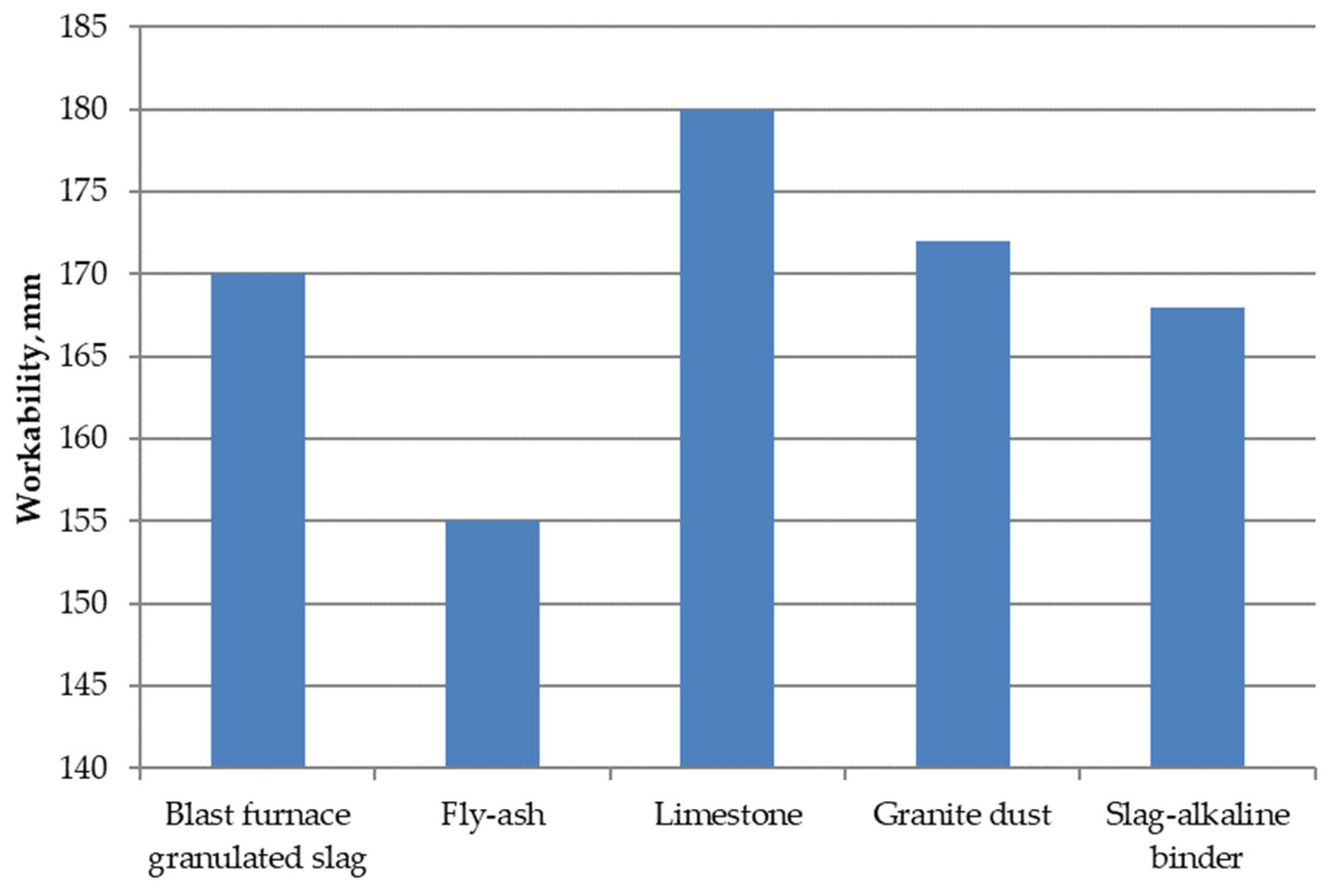
The analysis of the obtained data (Figure 6) makes it possible to conclude that to ensure the formability of mixtures using different mineral additives, the workability of the cone on the shaking table is different. It is the smallest for a cement–ash composition, which is explained by the spherical shape of the fly ash part, which provides the necessary extrudability with the lowest water consumption of the concrete mixture [20,39].

Figure 6.
Graphic depictions of the mobility of mixtures for a 3D printer.
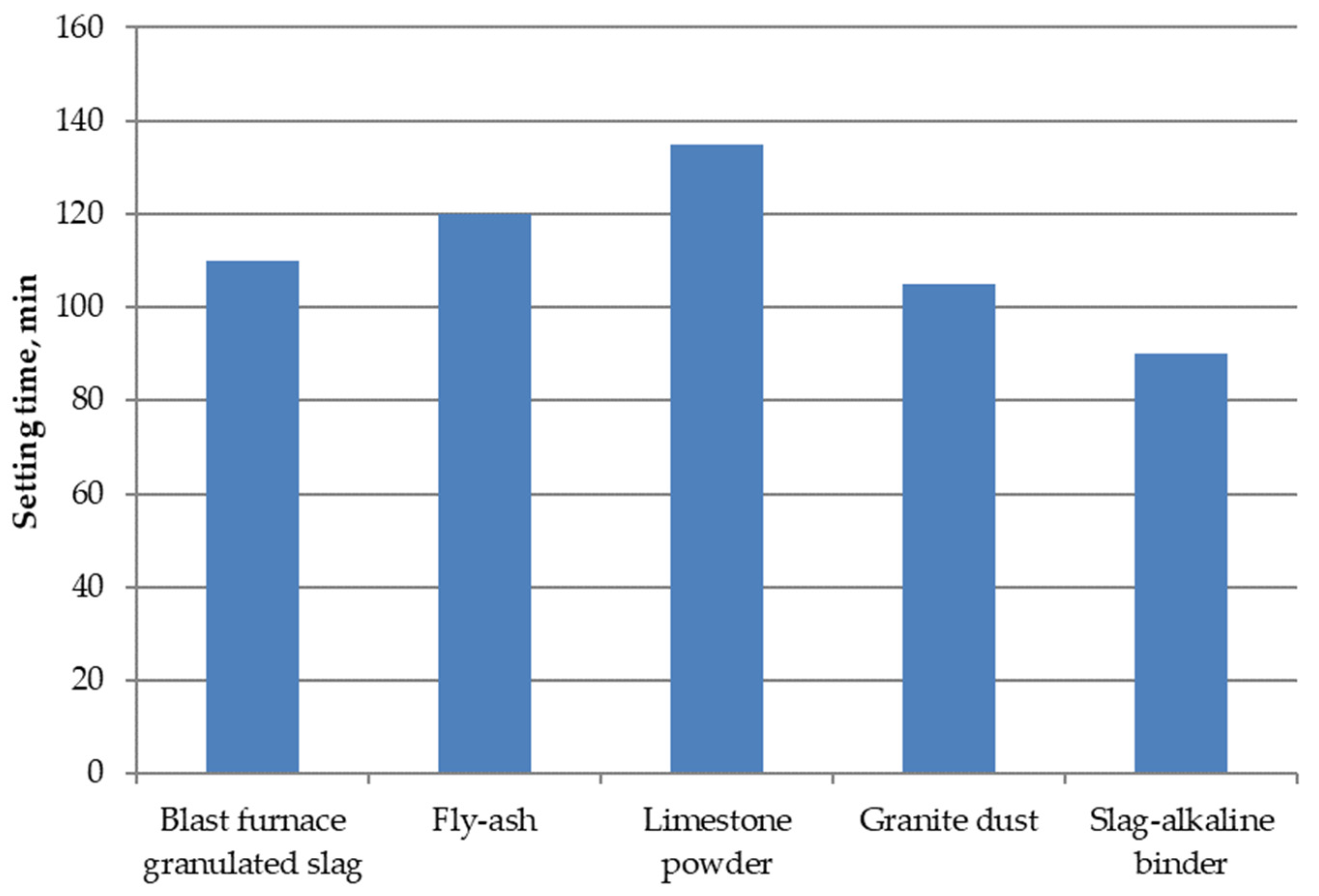
The beginning of the hardening or “printing window” (Figure 7) is the largest when using limestone and the smallest with a slag–alkaline binder; the different speeds of the processes of structuring cement pastes with the use of mineral additives can explain this.
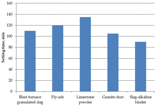
Figure 7.
Graphic depictions of the initial setting time of mixtures for a 3D printer.
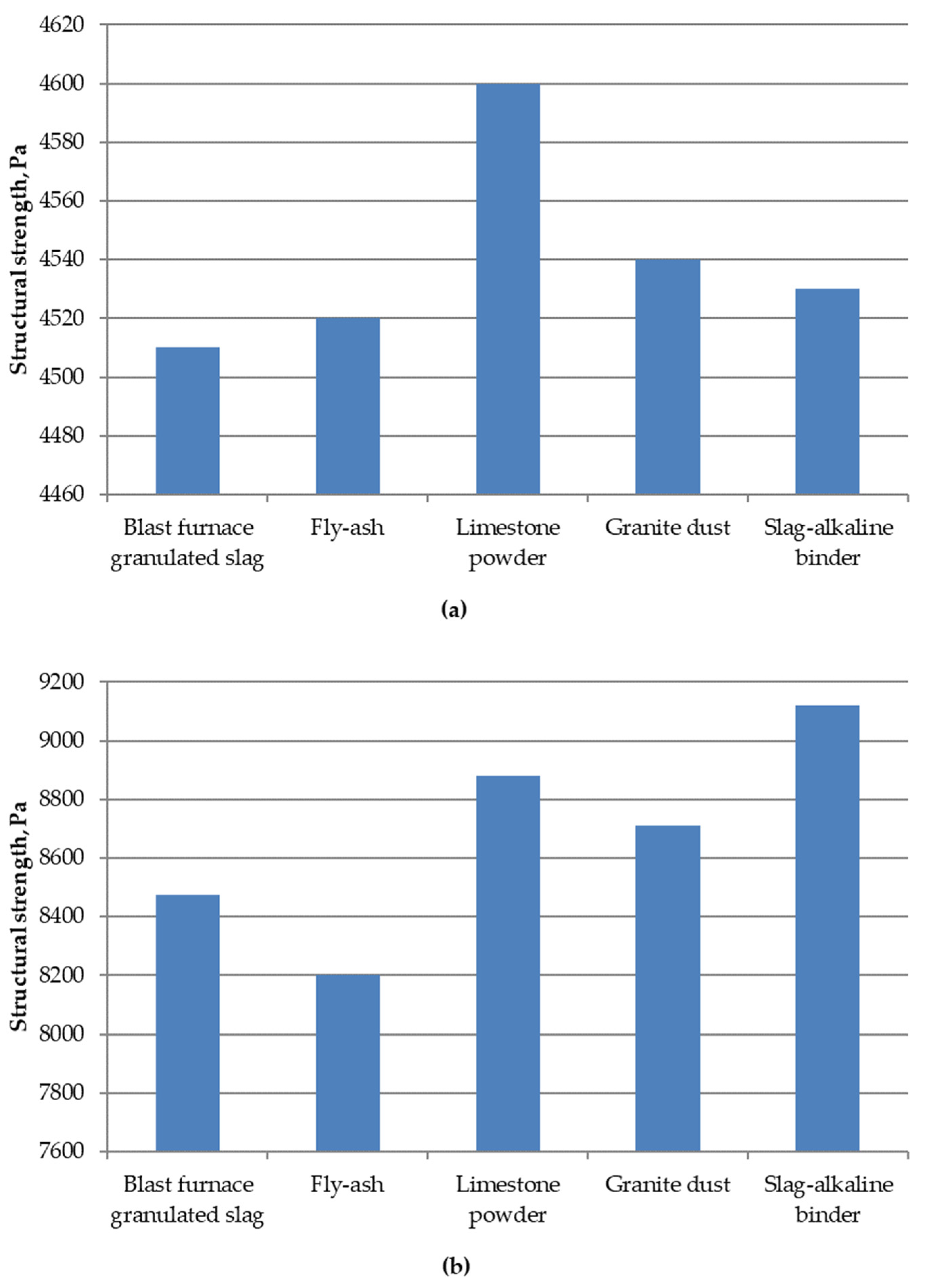
The structural strength of the mixtures for 3D printer (Figure 8) after 20 and 40 min of mixing is the highest when using limestone and slag–alkaline binder, respectively, which is consistent with the beginning of hardening of these mixtures. The most minor structural strength achieved is with fly ash, which can be explained by its spherical parts, which cause the sample to spread under the action of the load from the upper layers.

Figure 8.
Graphic depictions of the structural strength of mixtures for a 3D printer (a) 20 min after mixing and (b) 40 min after mixing.
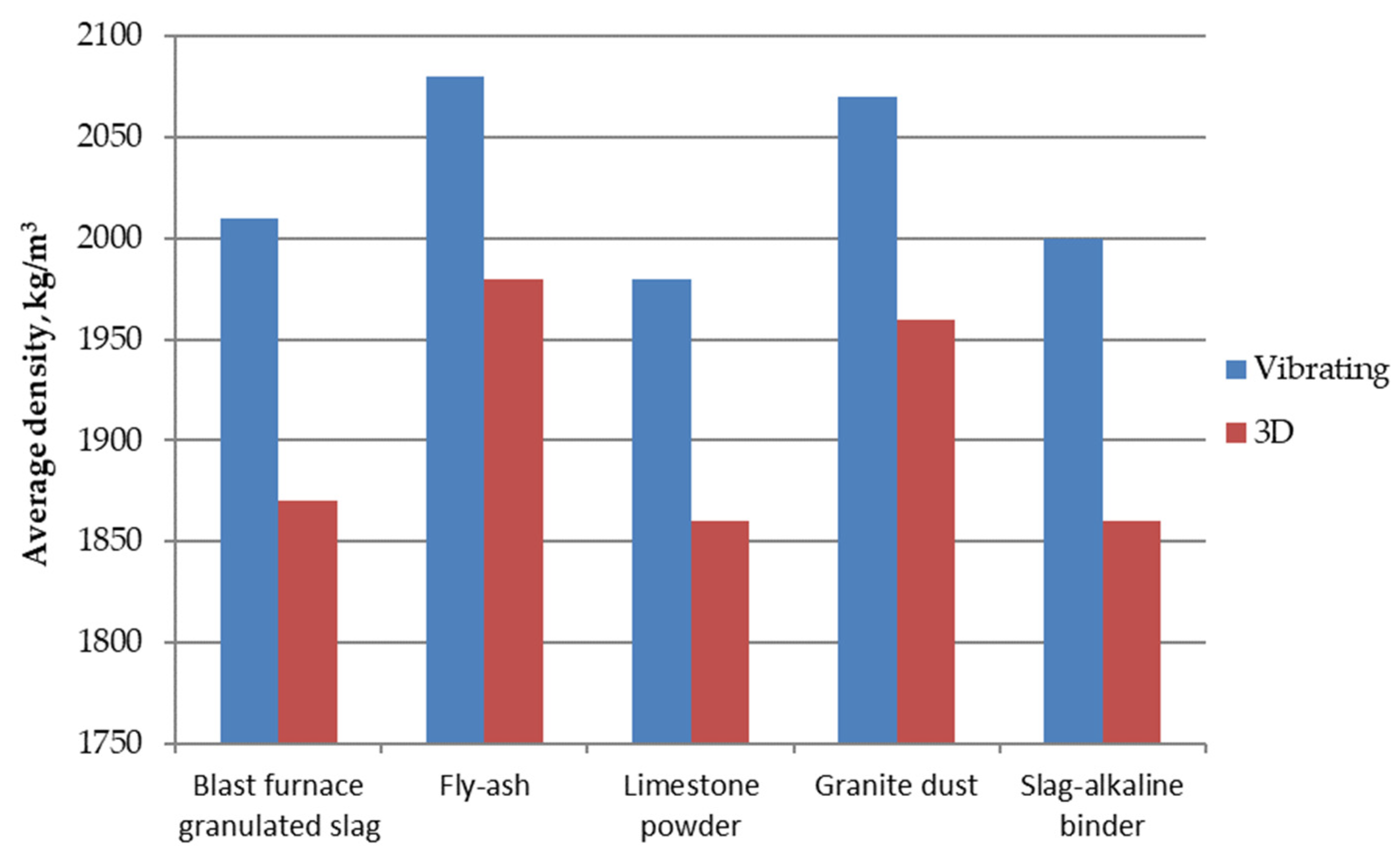
According to Figure 9, a significant decrease in the average density, up to 140 kg/m3, is observed in the samples obtained with the help of a 3D printer based on slag, slag–alkaline binder, and limestone, which can be explained by the increased water consumption of the mixtures. The lower density of 3D-printed materials compared to samples of vibrated materials is a direct consequence of the compaction of the material during vibration and better packing of sand grains. The direct consequence is a higher density of vibrated materials. Material densification results in higher strength parameters (see Table 6). The decrease in density when using granite dust and fly ash is smaller and achieved at 110 kg/m3 and 100 kg/m3, respectively.
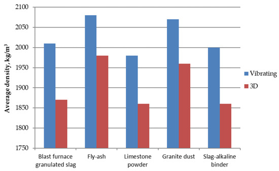
Figure 9.
Graphic depictions of the average density of mixtures for a 3D printer.
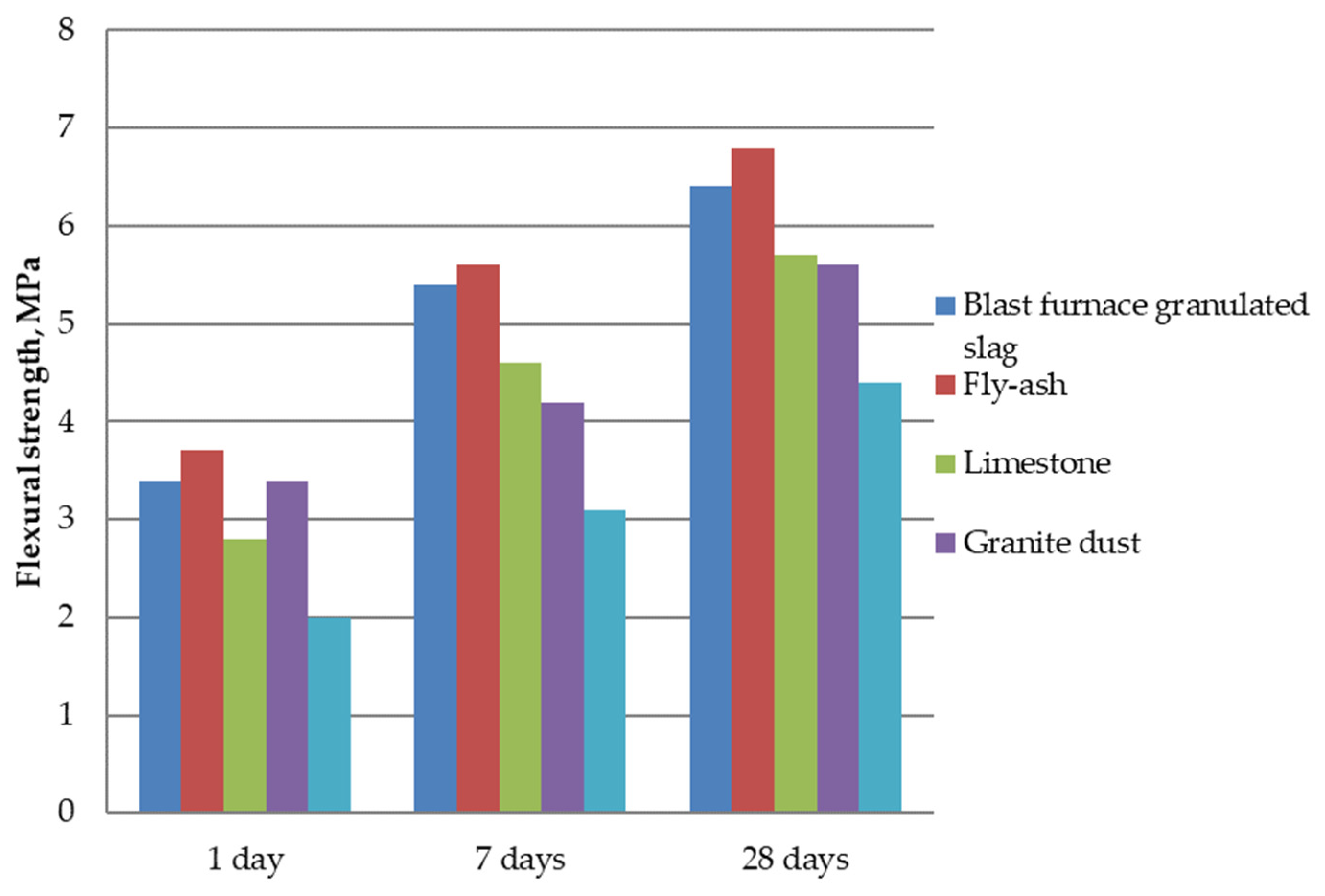
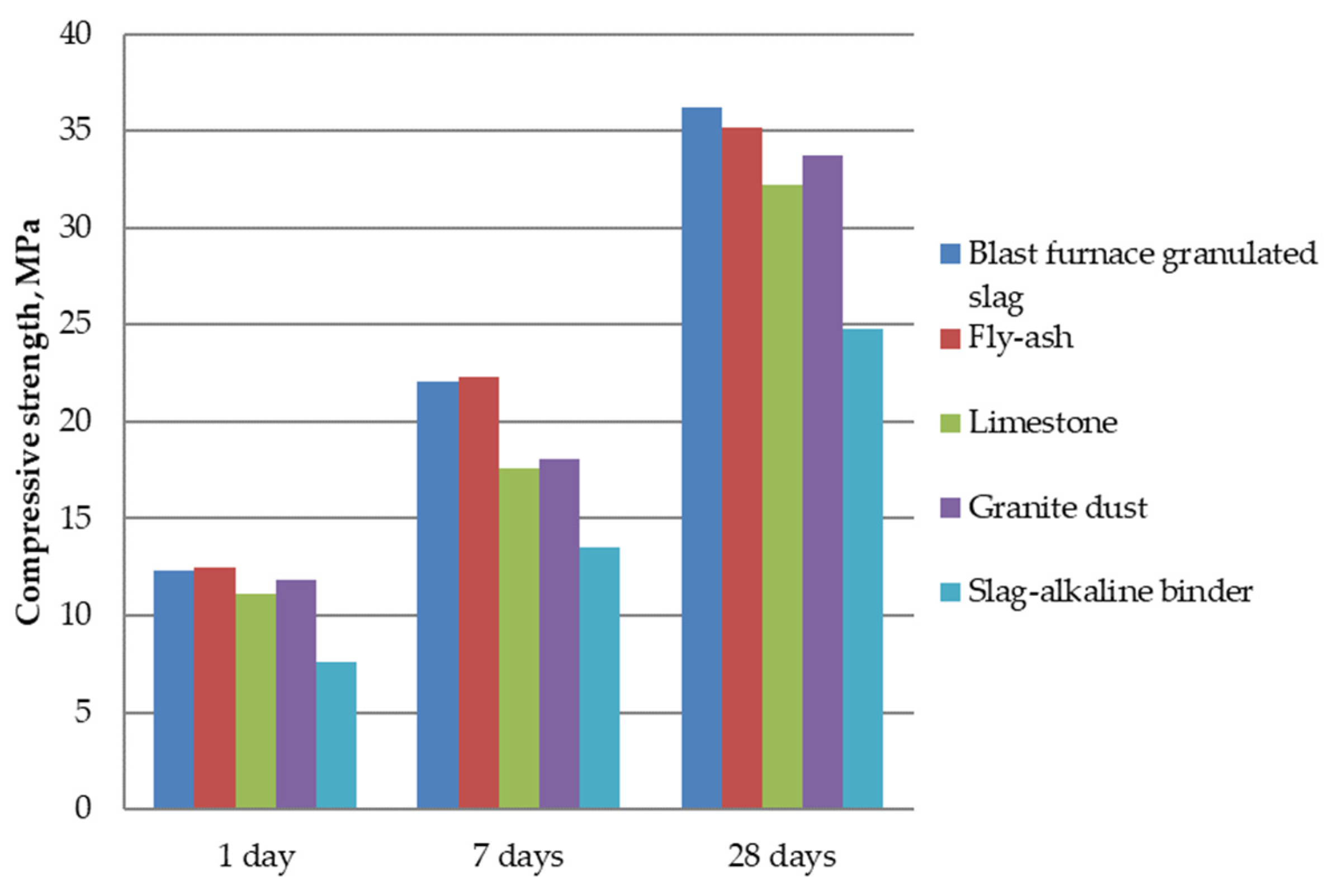
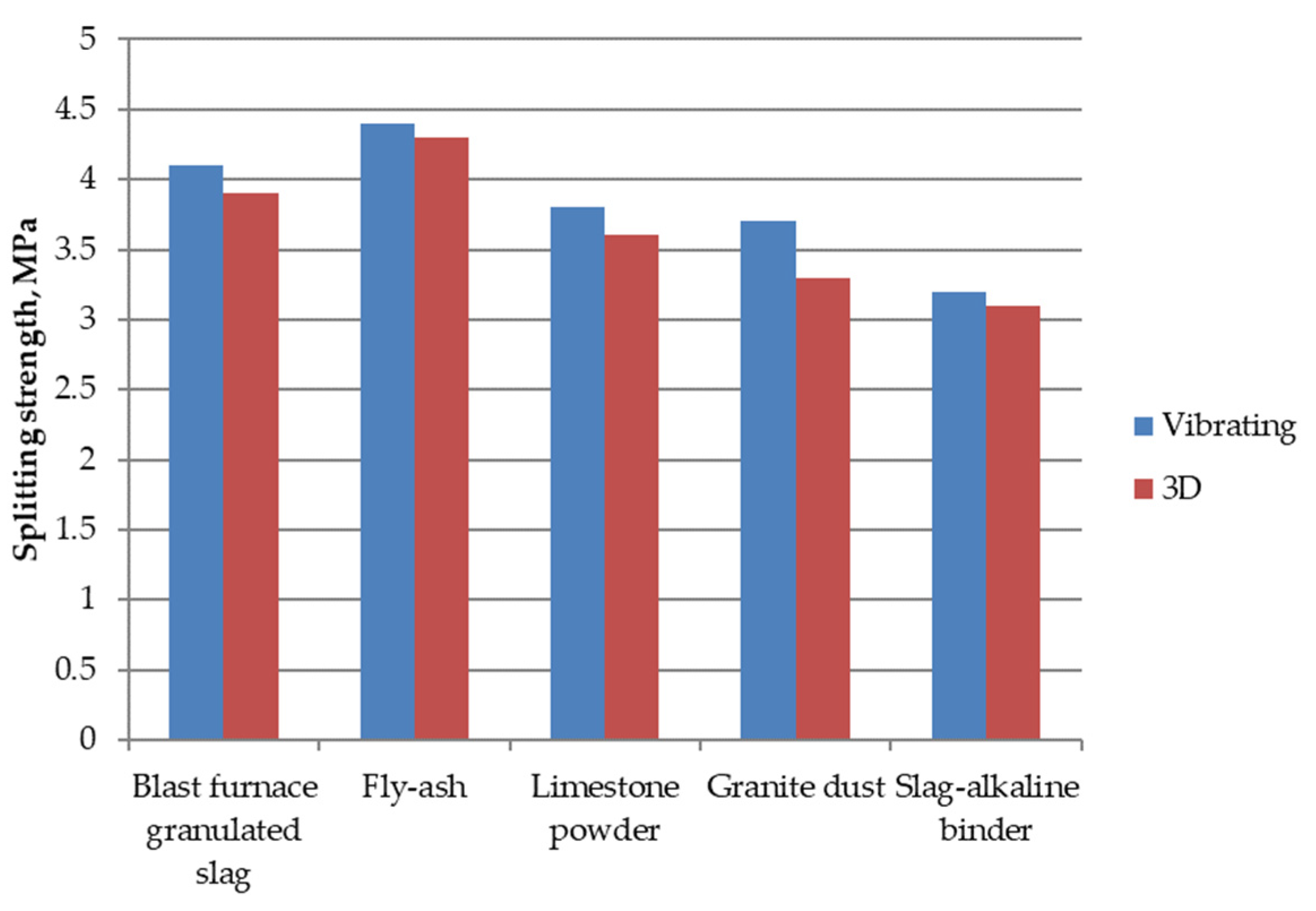
The highest values of bending strength (Figure 10) were obtained when using fly ash and blast furnace granulated slag, and the lowest with slag–alkaline binder, which can be explained by the amount and pozzolanic activity of mineral additives. A similar picture is observed for the effect of compression (Figure 11), splitting (Figure 12) and bending strength (Figure 13).

Figure 10.
Graphic depictions of bending strength of mixtures for a 3D printer.

Figure 11.
Graphic depictions of compressive strength of mixtures for a 3D printer.
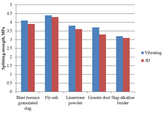
Figure 12.
Graphic depictions of the splitting strength of compacted concrete on a vibrating platform and with the help of a 3D printer.
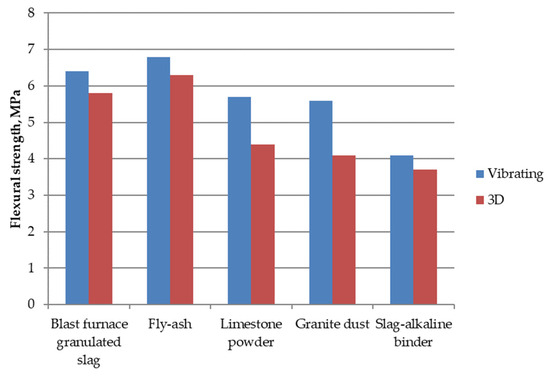
Figure 13.
Graphic depictions of the bending strength of mixtures produced on a vibrating platform and with the help of a 3D printer.
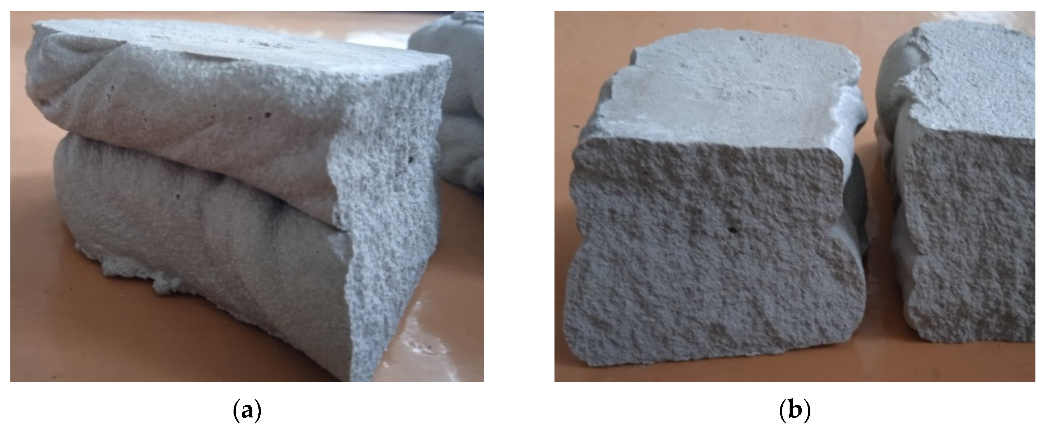
The nature of the destruction of the samples based on the slag–alkaline (Figure 14a) and the cement–ash binders (Figure 14b), after determining the bending strength, show that in the absence of defects, the destruction of the samples during splitting can occur both on the boundary of the layers (Figure 15a) and on another area (Figure 15b), with high uniformity and adhesive strength between the layers.
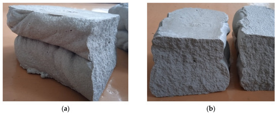
Figure 14.
Destruction of samples during the determination of bending strength for slag–alkaline (a) and the cement–ash binders (b).
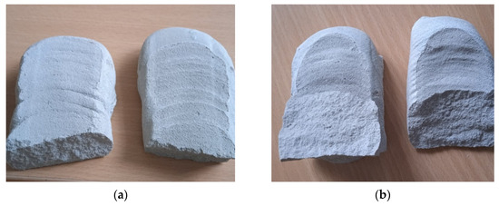
Figure 15.
Destruction of samples during the determination of splitting strength: (a) destruction along the boundary of superimposed layers (slag–alkaline binder, composition No. 5, Table 6); (b) destruction beyond the boundaries of superimposed layers (cement–ash binder, composition No. 2, Table 6).
A decrease in strength between layers when using a slag–alkaline binder can be caused by accelerated hardening of the mixture and, consequently, the appearance of a non-uniform structure, violation of the integrity, and the possible formation of defects at the boundary of the layers.
According to the graphs in Figure 16, we can observe that samples of the same material composition made on a vibrating platform have slightly higher compressive strength compared to samples made using a 3D printer. This can be explained by a certain lack of compaction of the mixtures during their extrusion molding. The decline in strength is the smallest when using fly ash.
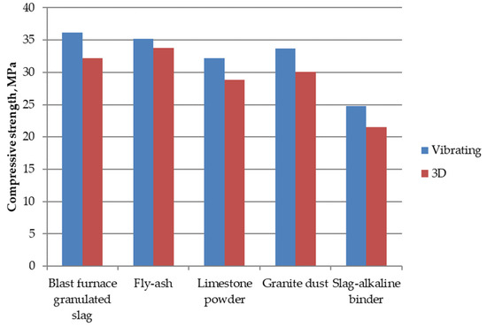
Figure 16.
Graphic depictions of the compressive strength of samples made on a vibrating platform and with the help of a 3D printer.
Compensation for an insufficient compaction of mixtures on a 3D printer is possible by introducing additives of hardening activators (up to 4% of the binder) into the composition of such concrete. In the composite cement–ash binder, this allows, with a specific reduced density, to obtain higher compressive and bending strength, which is given in Table 7. The content of the composite binder in these tests is 500 kg/m3 of the mixture. It is possible to increase the strength indicators when using granite dust and limestone powder with the introduction of a superplasticizer additive (0.2…0.5%).
Table 7.
Results of concrete strength (MPa) research for a 3D printer.
4. Conclusions
- In this paper, we investigated the comparative effect of dispersed mineral products of technogenic origin on the properties of mixtures suitable for 3D printing.
- A comparison was made of the test results of the properties of samples printed on a 3D printer with samples made according to the same recipes on a vibrating platform.
- The initial setting time or “printing window” is most significant when using limestone. The smallest initial setting time observed for the slag–alkaline binder.
- The structural strength of mixtures for 3D printers 20 and 40 min after mixing is the highest when using limestone and slag–alkaline binder, respectively, and the lowest when using fly ash.
- The highest values of bending, splitting, and compressive strength were obtained when using fly ash and blast furnace granulated slag, and the lowest for the slag–alkaline binder.
- Samples of the same material composition made on a vibrating platform have slightly higher compressive strength than those made using a 3D printer, which is explained by the lack of compaction of the mixtures. The slightest drop in strength is shown when using fly ash.
- Compensation for insufficient compaction of mixtures on a 3D printer is possible due to the introduction of additives of a hardening activator, NaOH (up to 4% of the binder weight), and superplasticizers (0.2…0.5%) into the composition of such concretes, as well as with their complex use.
- Use of industrial waste in 3D printing should help to manage waste that occurs locally, i.e., waste that does not require the transport of ingredients, or this transport will be significantly limited. Therefore, it is important to adjust the composition and design mixtures appropriate for local waste sources.
Author Contributions
Conceptualization, L.D. and V.M.; methodology, V.M.; software, V.M. and M.M.; validation, L.D., I.H. and K.M.; formal analysis, V.M. and M.M.; investigation, L.D. and V.M.; resources, I.H.; data curation, V.M. and M.M.; writing—original draft preparation, L.D. and V.M.; writing—review and editing, M.M., I.H. and K.M.; visualization, M.M. and K.M.; supervision, L.D. and I.H.; project administration, K.M.; funding acquisition, K.M. and I.H. All authors have read and agreed to the published version of the manuscript.
Funding
The research was supported by the Polish National Agency for Academic Exchange under the complementary activities to those undertaken by the University as part of the University Alliance European entitled STARS EU academic cooperation with Ukrainian universities, grant no. BNI-UE-2023-8. This research was co-funded by Polish National Centre for Research and Development in Poland, under the M-ERA.NET 3 program, grant number M-ERA.NET3/2021/144/3D-FOAM/2022.
Data Availability Statement
Raw data were generated at the National University of Water and Environmental Engineering in Ukraine and Cracow University of Technology. Derived data supporting the findings of this study are available from the corresponding author on request.
Acknowledgments
Author K.M. is supported by the Foundation for Polish Science (FNP). We would like to acknowledge support by the Ministry of Education and Science within the program “Implementation Doctorate”.
Conflicts of Interest
The authors declare no conflicts of interest.
References
- Perrot, A.; Rangeard, D.; Courteille, E. 3D Printing of Earth-Based Materials: Processing Aspects. Constr. Build. Mater. 2018, 172, 670–676. [Google Scholar] [CrossRef]
- Ali, M.H.; Issayev, G.; Shehab, E.; Sarfraz, S. A Critical Review of 3D Printing and Digital Manufacturing in Construction Engineering. Rapid Prototyp. J. 2022, 28, 1312–1324. [Google Scholar] [CrossRef]
- Wang, B.; Zhai, M.; Yao, X.; Wu, Q.; Yang, M.; Wang, X.; Huang, J.; Zhao, H. Printable and Mechanical Performance of 3D Printed Concrete Employing Multiple Industrial Wastes. Buildings 2022, 12, 374. [Google Scholar] [CrossRef]
- Dvorkin, L.; Marchuk, V.; Hager, I.; Maroszek, M. Design of Cement–Slag Concrete Composition for 3D Printing. Energies 2022, 15, 4610. [Google Scholar] [CrossRef]
- Wu, Y.; Liu, C.; Bai, G.; Liu, H.; Meng, Y.; Wang, Z. 3D Printed Concrete with Recycled Sand: Pore Structures and Triaxial Compression Properties. Cem. Concr. Compos. 2023, 139, 105048. [Google Scholar] [CrossRef]
- Chen, Y.; Chaves Figueiredo, S.; Li, Z.; Chang, Z.; Jansen, K.; Çopuroğlu, O.; Schlangen, E. Improving Printability of Limestone-Calcined Clay-Based Cementitious Materials by Using Viscosity-Modifying Admixture. Cem. Concr. Res. 2020, 132, 106040. [Google Scholar] [CrossRef]
- Chen, Y.; Veer, F.; Çopuroğlu, O. A Critical Review of 3D Concrete Printing as a Low CO2 Concrete Approach. Heron 2017, 62, 167–194. [Google Scholar]
- Chen, Y.; Veer, F.; Copuroglu, O.; Schlangen, E. Feasibility of Using Low CO2 Concrete Alternatives in Extrusion-Based 3D Concrete Printing. In RILEM Bookseries; Springer: Berlin/Heidelberg, Germany, 2019; Volume 19. [Google Scholar]
- Chen, Y.; Li, Z.; Figueiredo, S.C.; Çopuroğlu, O.; Veer, F.; Schlangen, E. Limestone and Calcined Clay-Based Sustainable Cementitious Materials for 3D Concrete Printing: A Fundamental Study of Extrudability and Early-Age Strength Development. Appl. Sci. 2019, 9, 1809. [Google Scholar] [CrossRef]
- Panda, B.; Unluer, C.; Tan, M.J. Investigation of the Rheology and Strength of Geopolymer Mixtures for Extrusion-Based 3D Printing. Cem. Concr. Compos. 2018, 94, 307–314. [Google Scholar] [CrossRef]
- Bentz, D.P.; Stutzman, P.E.; Zunino, F. Low-Temperature Curing Strength Enhancement in Cement-Based Materials Containing Limestone Powder. Mater. Struct. 2017, 50, 551. [Google Scholar] [CrossRef]
- Sanytsky, M.; Marushchak, U.; Olevych, Y.; Novytskyi, Y. Nano-Modified Ultra-Rapid Hardening Portland Cement Compositions for High Strength Concretes. In Lecture Notes in Civil Engineering; Springer: Berlin/Heidelberg, Germany, 2020; Volume 47. [Google Scholar]
- Juenger, M.C.G.; Siddique, R. Recent Advances in Understanding the Role of Supplementary Cementitious Materials in Concrete. Cem. Concr. Res. 2015, 78, 71–80. [Google Scholar] [CrossRef]
- Lothenbach, B.; Scrivener, K.; Hooton, R.D. Supplementary Cementitious Materials. Cem. Concr. Res. 2011, 41, 1244–1256. [Google Scholar] [CrossRef]
- Nerella, V.N.; Näther, M.; Iqbal, A.; Butler, M.; Mechtcherine, V. Inline Quantification of Extrudability of Cementitious Materials for Digital Construction. Cem. Concr. Compos. 2019, 95, 260–270. [Google Scholar] [CrossRef]
- Chaves Figueiredo, S.; Romero Rodríguez, C.; Ahmed, Z.Y.; Bos, D.H.; Xu, Y.; Salet, T.M.; Çopuroğlu, O.; Schlangen, E.; Bos, F.P. An Approach to Develop Printable Strain Hardening Cementitious Composites. Mater. Des. 2019, 169, 107651. [Google Scholar] [CrossRef]
- Le, T.T.; Austin, S.A.; Lim, S.; Buswell, R.A.; Gibb, A.G.F.; Thorpe, T. Mix Design and Fresh Properties for High-Performance Printing Concrete. Mater. Struct. 2012, 45, 1221–1232. [Google Scholar] [CrossRef]
- Ma, G.; Li, Z.; Wang, L. Printable Properties of Cementitious Material Containing Copper Tailings for Extrusion Based 3D Printing. Constr. Build. Mater. 2018, 162, 613–627. [Google Scholar] [CrossRef]
- Panda, B.; Ruan, S.; Unluer, C.; Tan, M.J. Improving the 3D Printability of High Volume Fly Ash Mixtures via the Use of Nano Attapulgite Clay. Compos. B Eng. 2019, 165, 75–83. [Google Scholar] [CrossRef]
- Dvorkin, L.; Zhitkovsky, V.; Sonebi, M.; Marchuk, V.; Stepasiuk, Y. Improving Concrete and Mortar Using Modified Ash and Slag Cements; CRC Press: Boca Raton, FL, USA, 2020. [Google Scholar]
- Sanjayan, J.; Nematollahi, B.; Xia, M.; Wang, L.; Guowei, M. 3D Concrete Printing with Low Carbon Cements; Butterworth-Heinemann: Oxford, UK, 2019; 416p. [Google Scholar]
- De Weerdt, K.; Kjellsen, K.O.; Sellevold, E.; Justnes, H. Synergy between Fly Ash and Limestone Powder in Ternary Cements. Cem. Concr. Compos. 2011, 33, 30–38. [Google Scholar] [CrossRef]
- Prokopski, G.; Marchuk, V.; Huts, A. The Effect of Using Granite Dust as a Component of Concrete Mixture. Case Stud. Constr. Mater. 2020, 13, e00349. [Google Scholar] [CrossRef]
- Dobiszewska, M.; Franus, W.; Turbiak, S. Analysis of the Possibility of Using Powder Basalt in Cement Mortar. J. Civ. Eng. Environ. Archit. 2016, 63, 107–114. [Google Scholar]
- Berodier, E.; Scrivener, K. Understanding the Filler Effect on the Nucleation and Growth of C-S-H. J. Am. Ceram. Soc. 2014, 97, 3764–3773. [Google Scholar] [CrossRef]
- Přikryl, R.; Török, Á.; Theodoridou, M.; Gomez-Heras, M.; Miskovsky, K. Geomaterials in Construction and Their Sustainability: Understanding Their Role in Modern Society. Geol. Soc. Spec. Publ. 2016, 416, 1–22. [Google Scholar] [CrossRef]
- Krivenko, P. Why Alkaline Activation—60 Years of the Theory and Practice of Alkali-Activated Materials. J. Ceram. Sci. Technol. 2017, 8, 323–334. [Google Scholar]
- Flatt, R.J.; Wangler, T. On Sustainability and Digital Fabrication with Concrete. Cem. Concr. Res. 2022, 158, 106837. [Google Scholar] [CrossRef]
- Kazemian, A.; Yuan, X.; Cochran, E.; Khoshnevis, B. Cementitious Materials for Construction-Scale 3D Printing: Laboratory Testing of Fresh Printing Mixture. Constr. Build. Mater. 2017, 145, 639–647. [Google Scholar] [CrossRef]
- Tay, Y.W.D.; Ting, G.H.A.; Qian, Y.; Panda, B.; He, L.; Tan, M.J. Time Gap Effect on Bond Strength of 3D-Printed Concrete. Virtual Phys. Prototyp. 2019, 14, 104–113. [Google Scholar] [CrossRef]
- Nerella, V.N.; Krause, M.; Mechtcherine, V. Direct Printing Test for Buildability of 3D-Printable Concrete Considering Economic Viability. Autom. Constr. 2020, 109, 102986. [Google Scholar] [CrossRef]
- Rushing, T.S.; Stynoski, P.B.; Barna, L.A.; Al-Chaar, G.K.; Burroughs, J.F.; Shannon, J.D.; Kreiger, M.A.; Case, M.P. Investigation of Concrete Mixtures for Additive Construction. In 3D Concrete Printing Technology; Elsevier: Amsterdam, The Netherlands, 2019; pp. 137–160. [Google Scholar]
- Mechtcherine, V.; Nerella, V.N.; Will, F.; Näther, M.; Otto, J.; Krause, M. Large-Scale Digital Concrete Construction—CONPrint3D Concept for on-Site, Monolithic 3D-Printing. Autom. Constr. 2019, 107, 102933. [Google Scholar] [CrossRef]
- Gosselin, C.; Duballet, R.; Roux, P.; Gaudillière, N.; Dirrenberger, J.; Morel, P. Large-Scale 3D Printing of Ultra-High Performance Concrete—A New Processing Route for Architects and Builders. Mater. Des. 2016, 100, 102–109. [Google Scholar] [CrossRef]
- Anton, A.; Reiter, L.; Wangler, T.; Frangez, V.; Flatt, R.J.; Dillenburger, B. A 3D Concrete Printing Prefabrication Platform for Bespoke Columns. Autom. Constr. 2021, 122, 103467. [Google Scholar] [CrossRef]
- Boscaro, F.; Quadranti, E.; Wangler, T.; Mantellato, S.; Reiter, L.; Flatt, R.J. Eco-Friendly, Set-on-Demand Digital Concrete. 3D Print. Addit. Manuf. 2022, 9, 3–11. [Google Scholar] [CrossRef] [PubMed]
- Hager, I.; Maroszek, M.; Mróz, K.; Kęsek, R.; Hebda, M.; Dvorkin, L.; Marchuk, V. Interlayer Bond Strength Testing in 3D-Printed Mineral Materials for Construction Applications. Materials 2022, 15, 4112. [Google Scholar] [CrossRef] [PubMed]
- IEA; UNEP. 2022 Building Construction Global Status Report; IEA: Paris, France; UNEP: Nairobi, Kenya, 2022; Volume 224. [Google Scholar]
- Sanytsky, M.; Sobol, H.; Markiv, M. Modified Cement Composites; NU “Lviv Polytechnic: Lviv, Ukraine, 2010. (In Ukrainian) [Google Scholar]


Disclaimer/Publisher’s Note: The statements, opinions and data contained in all publications are solely those of the individual author(s) and contributor(s) and not of MDPI and/or the editor(s). MDPI and/or the editor(s) disclaim responsibility for any injury to people or property resulting from any ideas, methods, instructions or products referred to in the content. |
© 2024 by the authors. Licensee MDPI, Basel, Switzerland. This article is an open access article distributed under the terms and conditions of the Creative Commons Attribution (CC BY) license (https://creativecommons.org/licenses/by/4.0/).