In recent years, there has been continuous research on precision fertilizer dischargers around the world. There are four main types of fertilizer dischargers: spiral fertilizer dischargers, groove wheel fertilizer dischargers, disc fertilizer dischargers, and air-feed fertilizer dischargers. In order to achieve precise fertilizer dosing and distribution, researchers conducted in-depth research.
2.1. Research Status of Spiral Fertilizer Dischargers
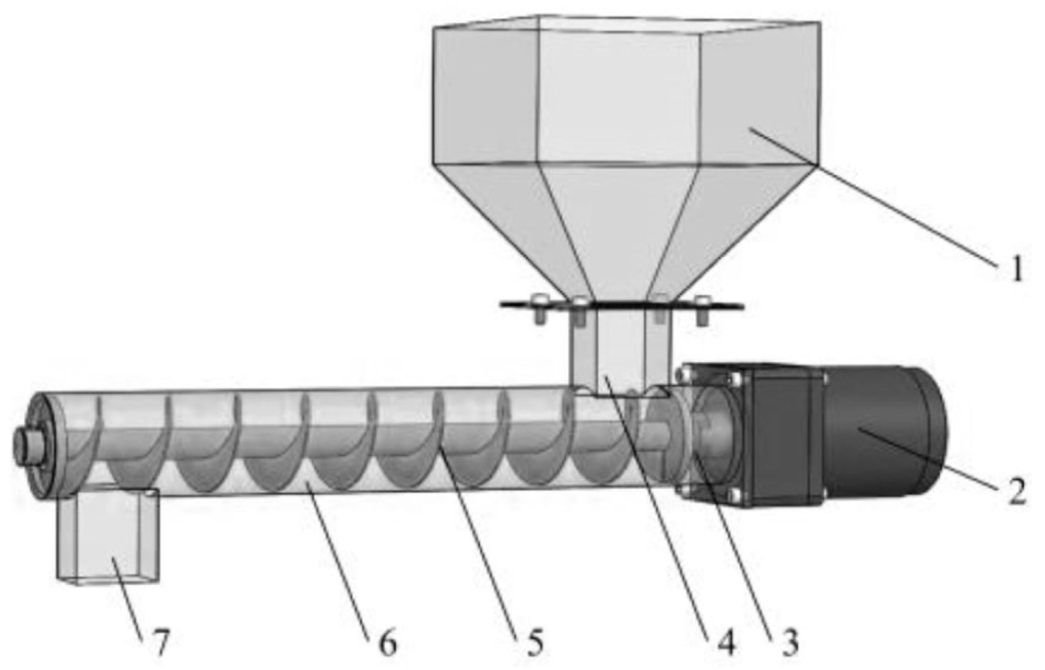
The working principle of spiral fertilizer dischargers is as follows: the spiral blades rotate around the axis, and under the pushing of the blades, the fertilizer in the fertilizer box is transported to the fertilizer discharge port and discharged. Its structure is shown in
Figure 1 [
7]. This fertilizer discharger has low requirements for the physical properties of fertilizers and can be flexibly used for the application of granular fertilizers and powdered fertilizers [
8]. It is low in price and has a simple structure. It is suitable for a variety of fertilizers with different physical properties. The amount of fertilizer can be adjusted according to the user’s needs. This simple structure is relatively uniform and stable when discharging fertilizer. However, when fertilizing at a low rotation speed, fertilizer quality fluctuates greatly and the fertilizer discharge is uneven.
The work of international researchers focuses on studying the impact of the spiral blade structure and working parameters on the performance of spiral fertilizer dischargers through discrete element simulation, bench testing, or the development of new designs for spiral fertilizer dischargers and attempts to optimize their conveying effect by adjusting key structural and working parameters to improve the accuracy and stability of fertilizer discharge dosing.
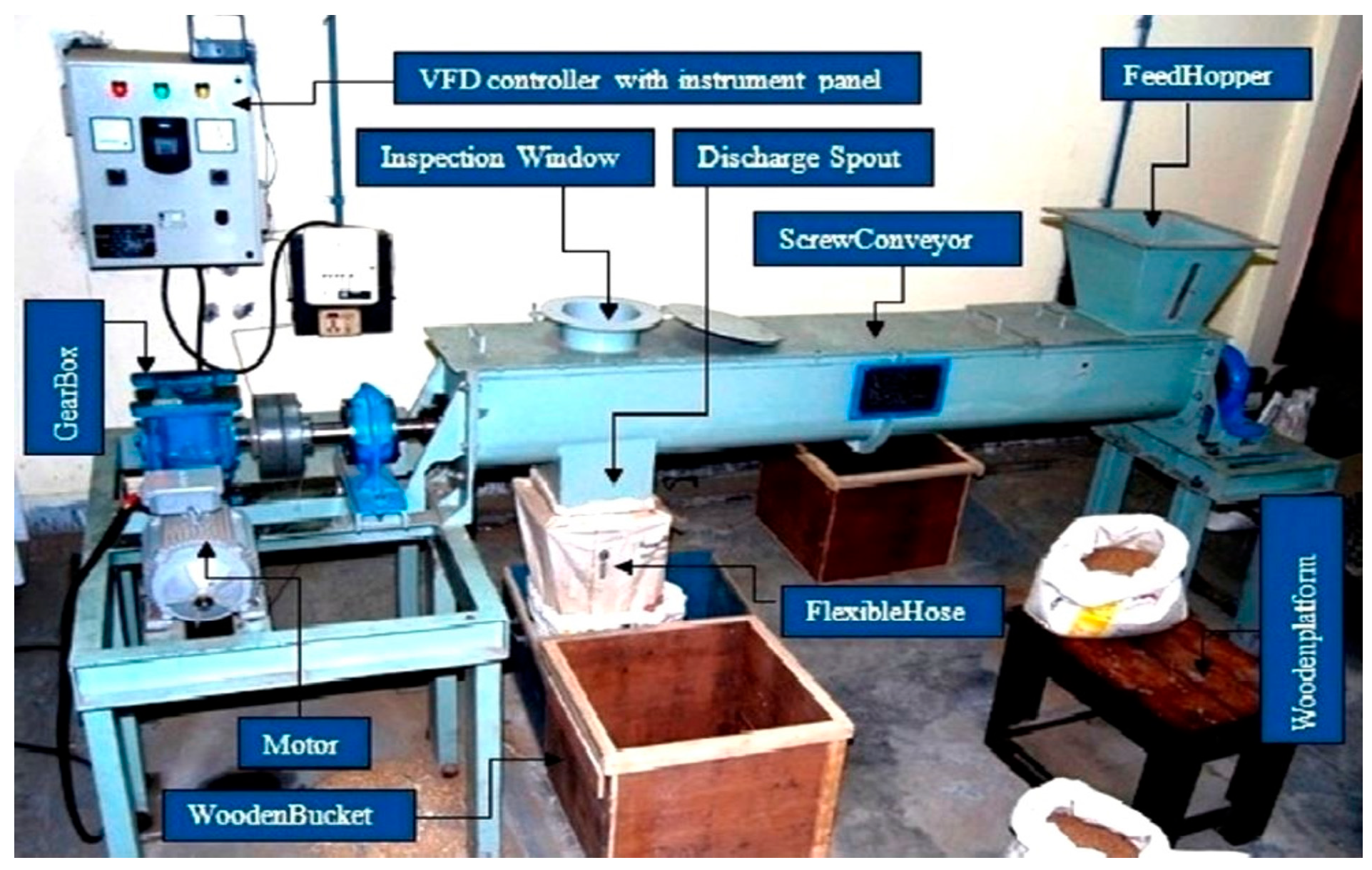
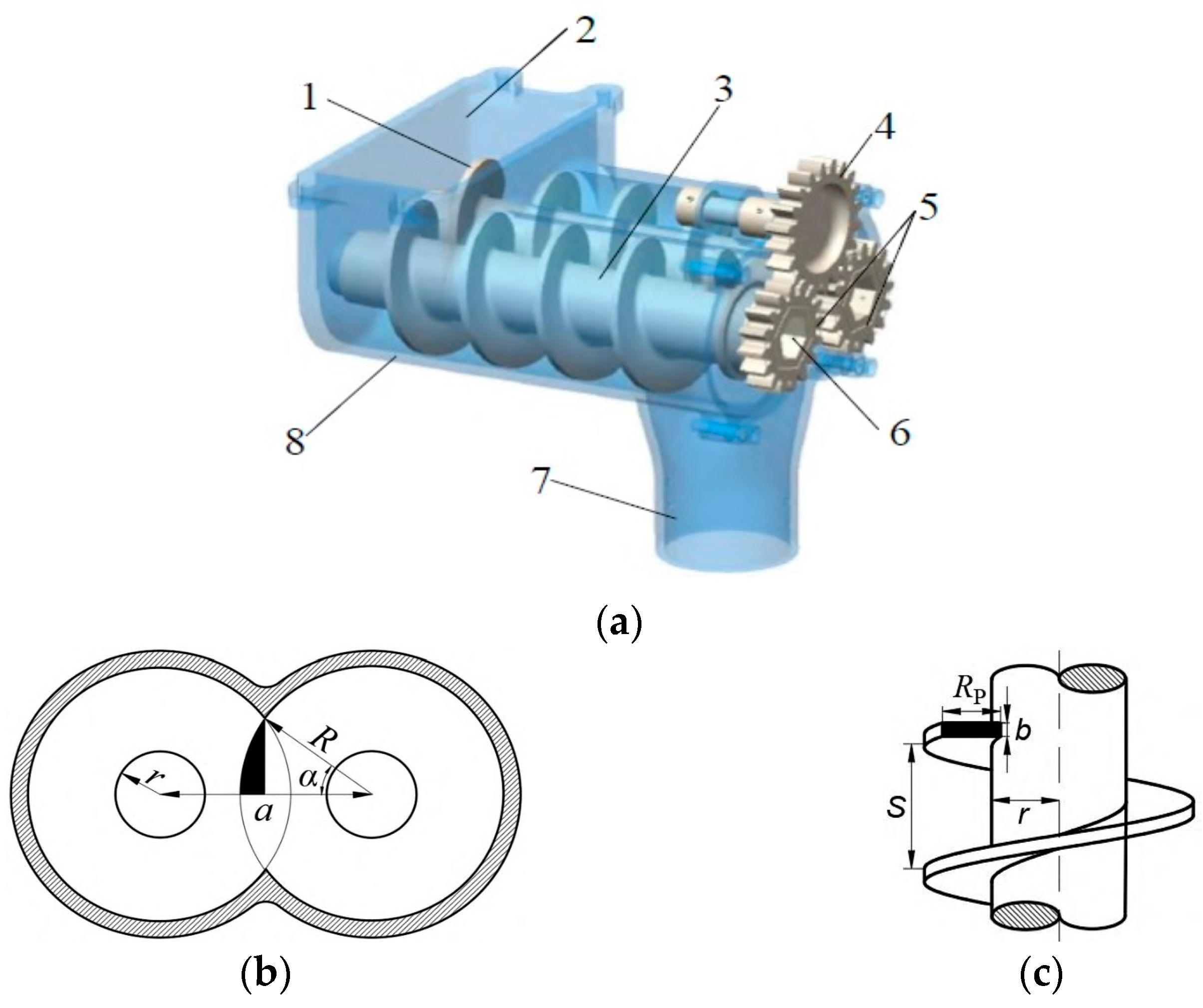
Mondal et al. [
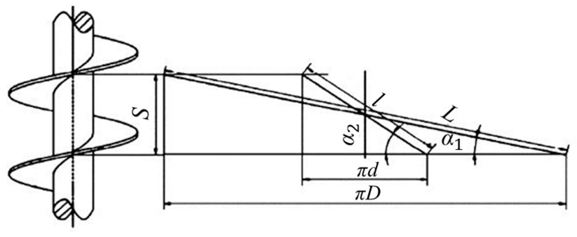
9] designed a conveying screw machine for the short-distance transportation of small-particle materials. Its structure is depicted in
Figure 2. A bench test study on the filling rate at different screw speeds was conducted, and it was found that when the speed is between 15 and 21 rpm, the filling factor remains within the range of 0.76~0.81, which means the machine has high accuracy when applied to fertilizer transportation.
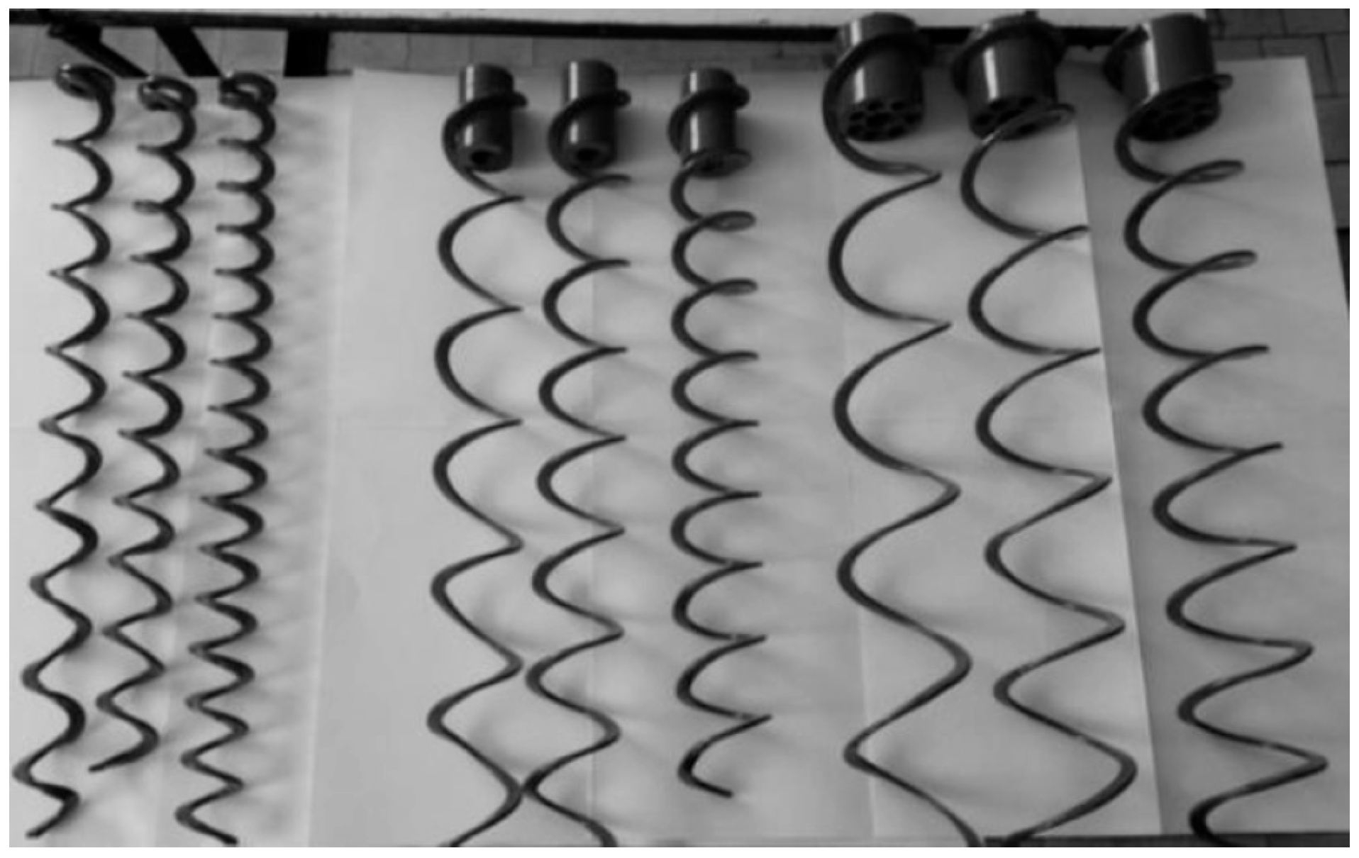
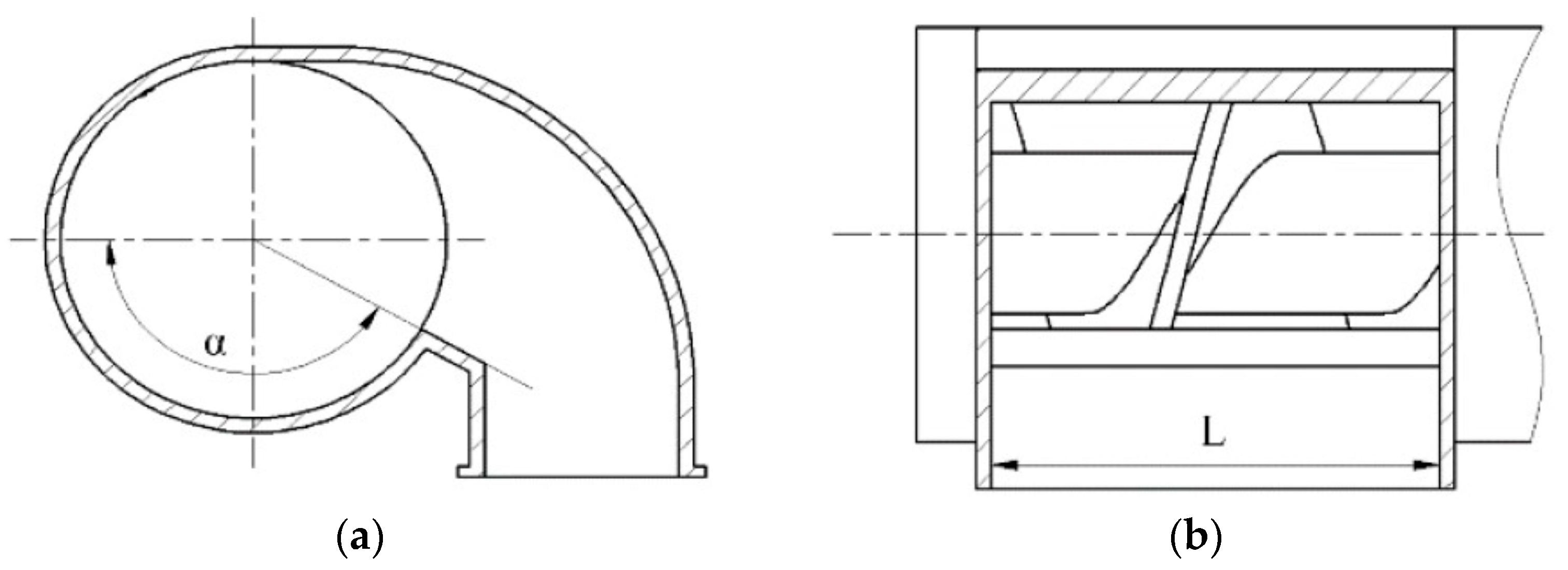
Lyalin et al. [
10] optimized the spiral distributor (SVD) working-body spiral screw (
Figure 3) through multi-factor experiments to improve fertilizer discharge accuracy and reduce unevenness. When the fertilizer feed rate is 320 kg per hour, the optimal structural parameters of the spiral screw are a diameter of 49 mm, a pitch of 1.05d (51.45 mm), and a gap of 2.5 mm, and the coefficient of variation in the fertilizer discharge stability does not exceed 0.2%; Meanwhile, when the fertilizer feed rate is 1450 kg per hour, the parameters are a diameter of 90 mm, a pitch 1.25 times the diameter (112.5 mm), and a gap of 7.5 mm. The coefficient of variation in the fertilizer discharge stability does not exceed 0.4%.
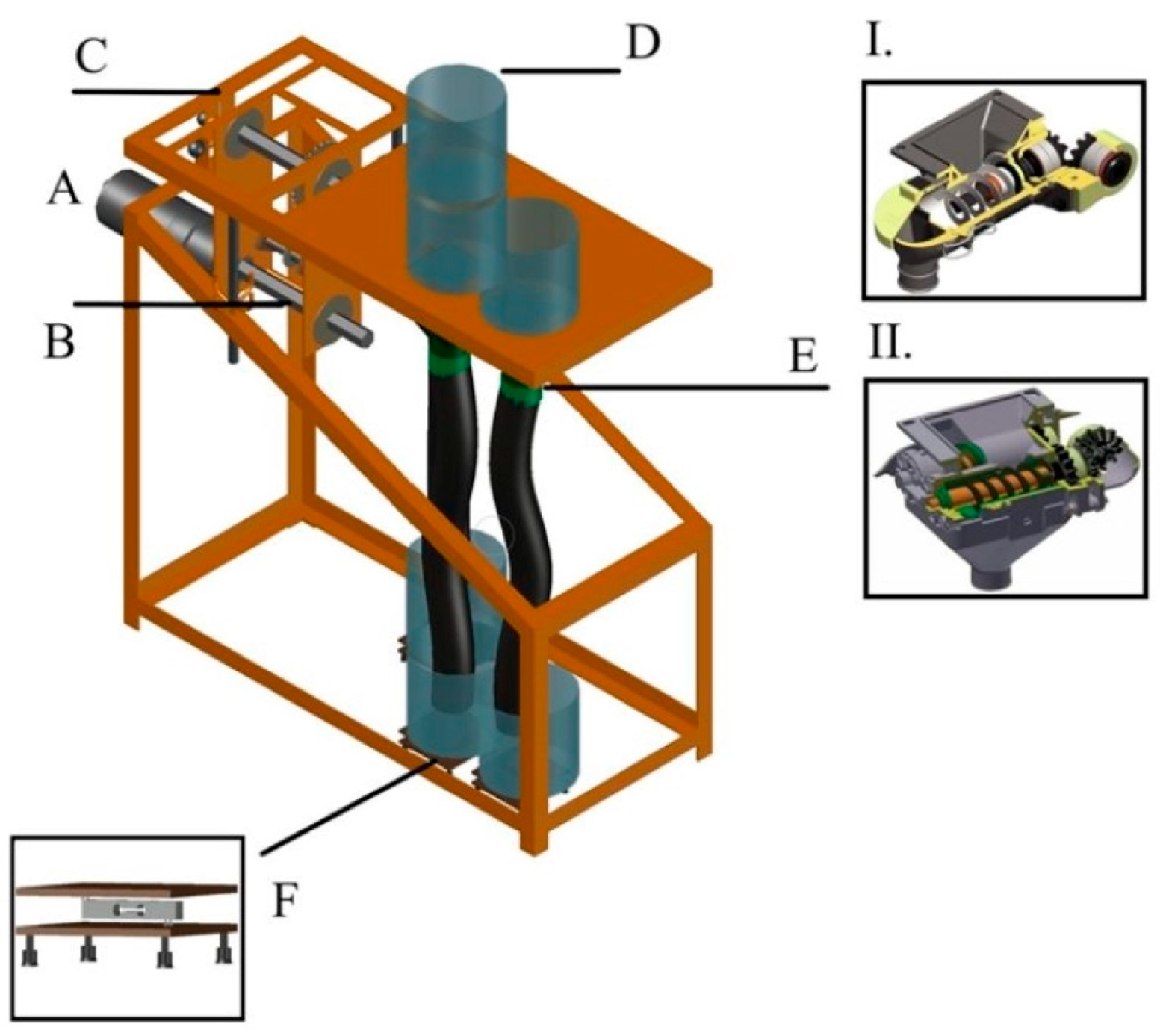
Zimmermann et al. [
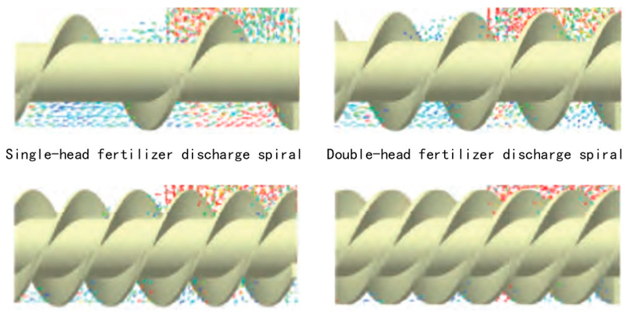
11] compared the performance of two nitrogen, phosphorus, and potassium granular fertilizer formulas in a spiral fertilizer discharger at three operating speeds. During the experiment, an automated workbench was built to evaluate the performance of single-spiral and double-spiral fertilizer dischargers, as shown in
Figure 4. Two nitrogen, phosphorus, and potassium granular fertilizer formulas (04-14-08 and 04-30-10) were selected for the experiment and tested at different angular velocities. After the test was completed, the flow data were collected for statistics and analysis. It was concluded that as the speed increases, the single-spiral fertilizer discharger shows greater uniformity compared to the double-spiral fertilizer discharger. Although the speeds of 7 and 10 kph increased the flow rate of both granular fertilizers, as expected, the 04-30-10 fertilizer obtained the most even distribution at the lowest speed of 4 kph.
The work of Chinese researchers primarily centers on the design and optimization of the structure and working parameters of spiral blades. Using a method that combines discrete element simulation with bench and field trials, the parameters of the spiral blades are continuously optimized to improve the stability and uniformity of fertilizer discharge dosing.
Zhao Liang et al. [
12,
13,
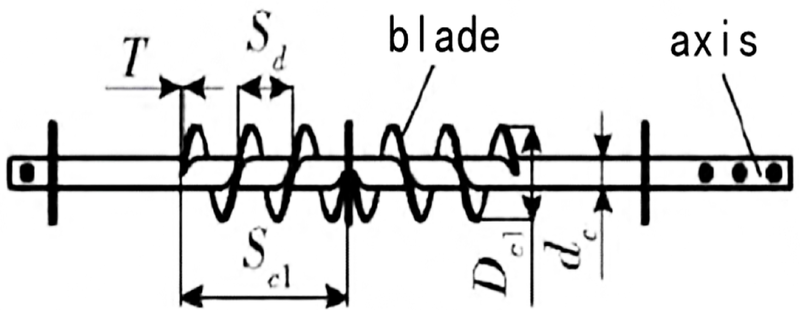
14] designed a small-scale spiral quantitative fertilizer discharger, examining the discharge process of three types of fertilizers (urea, compound fertilizer, and organic fertilizer) through discrete element simulation. They established a mathematical model and conducted single-factor and quadratic regression orthogonal rotation combined tests. The order of factors affecting the fertilizer discharge amount is as follows: fertilizer discharge shaft rotating speed, pitch, and spiral blade diameter. Combined with bench testing, optimized parameters were determined to be a diameter of the spiral blade (as shown in
Figure 5) of 92 mm, a pitch of 56 mm, and a rotation speed of the fertilizer discharge shaft of 39 rpm. The stability and uniformity of fertilizer discharge were found to be satisfactory, with the measured average coefficient of variation of fertilizer discharge stability at 12.25%. The average relative error between the simulation and experiment was 8.51%. Fertilization in mango orchards meets the requirements well.
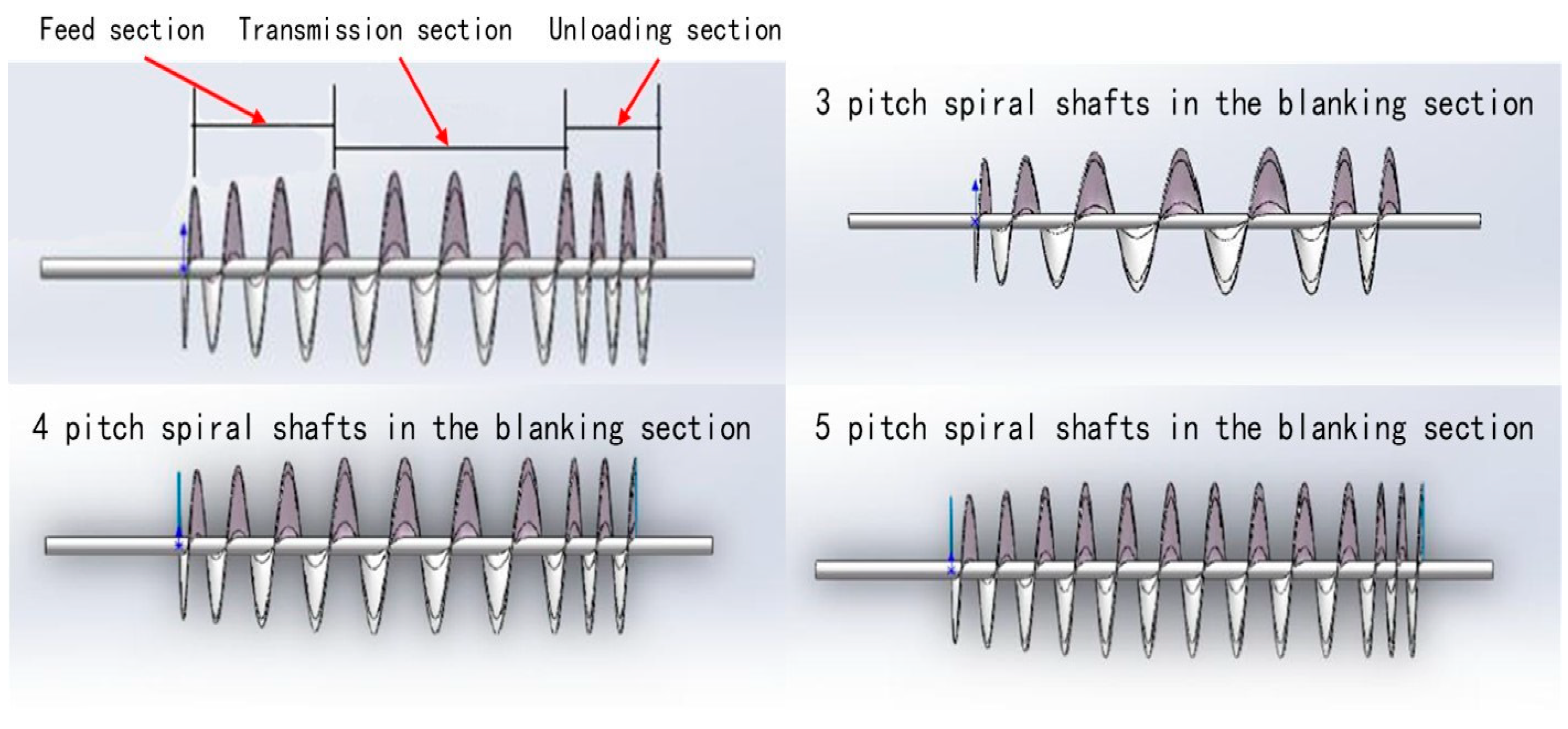
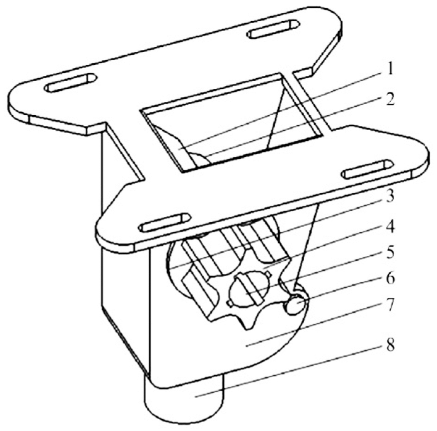
Wang Jie [
15] employed discrete element simulation to investigate the organic fertilizer discharger, with the aim of revealing the movement process of fertilizer particles within it. Additionally, the study aimed to analyze the correlation between the amount of discharged fertilizer and both the rotation speed of the discharge shaft and the number of pitches in the variable diameter and variable pitch section of the shaft’s feeding section. The structure of the fertilizer discharge shaft is illustrated in
Figure 6. Through two-factor and three-level simulation tests along with field trials, it was concluded that the rotation speed of the fertilizer discharge shaft has a more significant impact on the discharged fertilizer amount compared to the number of pitches in the variable diameter and variable pitch section of the shaft. Notably, when the number of pitches in the feeding section of the fertilizer discharge shaft is set at three, the stability variation coefficient of fertilizer discharge can be reduced to the minimum level, ranging from 6.93% to 7.50%, aligning with relevant industry standards.
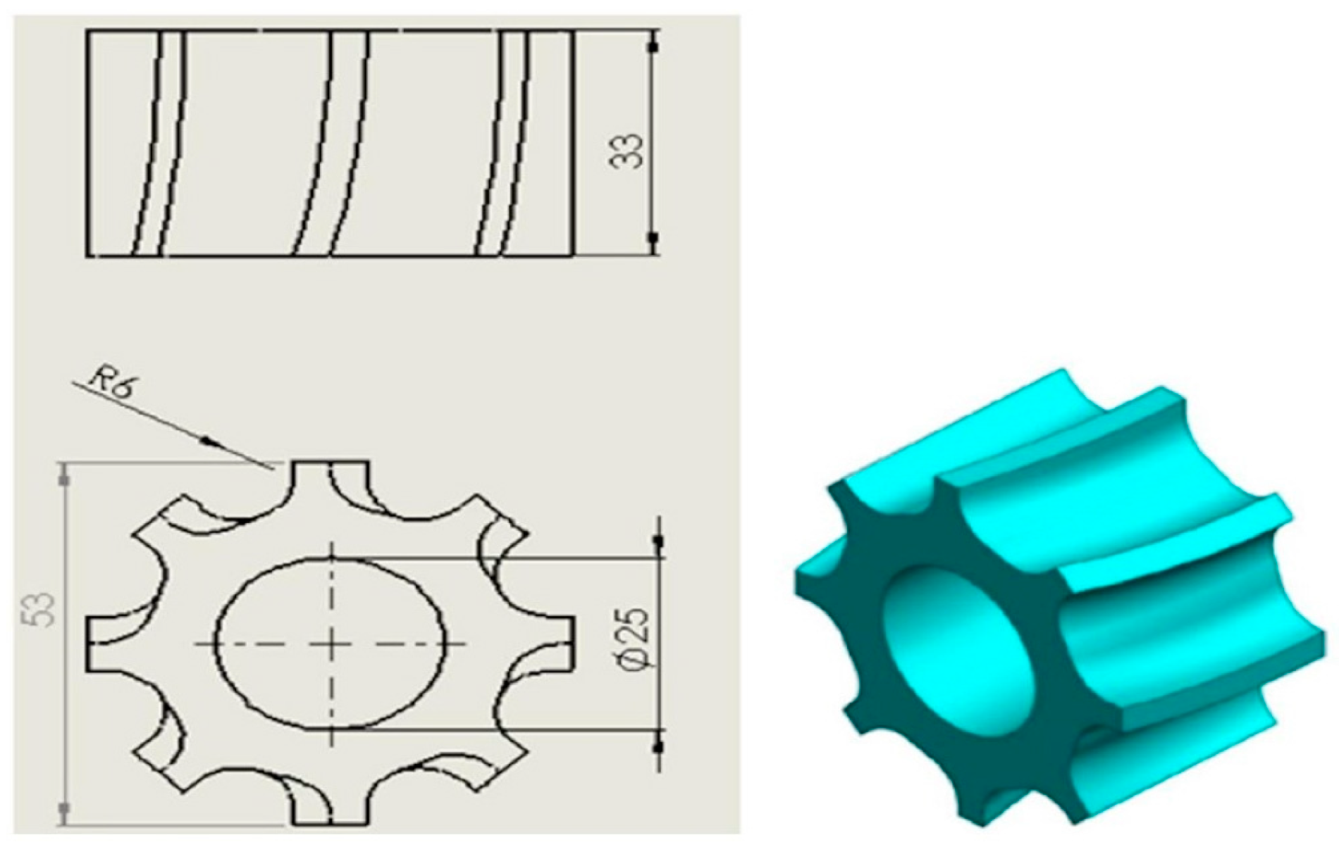
Xiao Wenli et al. [
16,
17] devised a four-head, spiral, double-row fertilizer discharger tailored for rapeseed cultivation. The structure of the fertilizer discharge spiral blade is depicted in
Figure 7. They executed single-factor discrete element analysis experiments aimed at simulating the movement of compound fertilizer particles within the fertilizer discharger. Through comparative experiments and iterative optimization, it was ascertained that the four-head fertilizer discharge spiral configuration should be adopted, with optimal performance achieved at a pitch of 24 mm. Combining bench and field trials, it was deduced that maintaining a fertilizer discharge spiral blade speed within the range of 40 to 60 rpm ensures that the variation coefficient of the fertilizer discharge uniformity for the three fertilizers remains below 6.8%. Additionally, the stability of the total fertilizer discharge and the consistency coefficient of variation for the double-row fertilizer discharge do not exceed 2.6%. Field trial results indicate a relative error of 2.33% between the actual and target fertilizer application amounts, meeting the requisites for basal fertilizer application quantity and fertilizer uniformity.
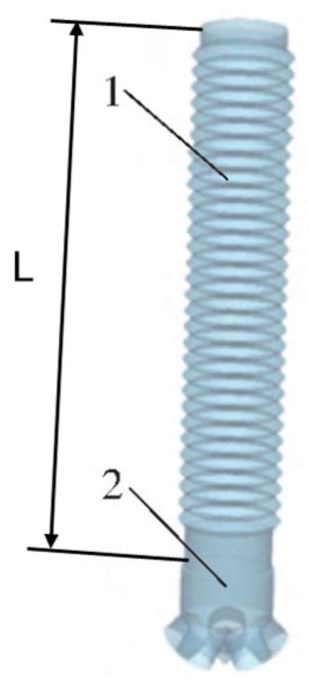
Liu Wenzheng et al. [
18] devised the bidirectional spiral blade for the fertilizer discharge apparatus of the double-side deep fertilization device used in potato cultivation. Through a combination of kinematic analysis and single-factor discrete element simulation testing of polyaspartate boric acid compound fertilizer within the fertilizer discharge apparatus, optimal parameters for the two-side spiral device were determined to be a single-spiral blade length of 120 mm, a spiral outer diameter of 56 mm, and a pitch of 45 mm. Its structural configuration is depicted in
Figure 8. Subsequently, the apparatus underwent testing under static working conditions, resulting in a concluded coefficient of variation for fertilizer discharge uniformity of 2.29%. This fertilizer discharger exhibits commendable stability in the fertilizer discharge.
To further enhance the precision of fertilizer discharge dosing from the spiral fertilizer discharger, Chinese researchers studied the structural parameters of the fertilizer discharge port.
Fang Longyu et al. [
19,
20] investigated the structure of the fertilizer discharge port, analyzing its impact on the performance of the boron sulfate compound fertilizer discharge. Through discrete element orthogonal simulation tests and bench trials, the optimal parameters are determined as follows: an outlet angle of 135 degrees and a length of 40 mm (1.5 times the pitch), as illustrated in
Figure 9. Combined with the field trial verifications, it was observed that the optimized fertilizer discharge stability and uniformity of fertilizer discharger were significantly enhanced, with the variation coefficient of fertilizer discharge not exceeding 8.22%. Moreover, the error in the fertilization amount was less than 4%, meeting the precise fertilizer discharge requirements for corn fields per acre.
In addition, in order to make breakthroughs in the precise fertilizer discharge dosing from the spiral fertilizer discharger, Chinese researchers are also dedicated to exploring new designs for spiral fertilizer dischargers.
To address the issue of flow fluctuation in the fertilizer discharge from single spiral fertilizer dischargers, Li Xin et al. [
21] devised a spiral double-wheel fertilizer discharger, as depicted in
Figure 10. The impact of structural parameters on the performance of the Stanley compound fertilizer discharge was theoretically analyzed. Through the establishment of a discrete element mathematical model, a genetic algorithm was employed to optimize the fertilizer discharger’s structure. Following optimization, the structural parameters are determined to be a center distance of 49.8 mm, a pitch of 32.5 mm, a blade height of 15.2 mm, a blade thickness of 2.3 mm, and a spiral blade inner diameter of 13.6 mm. The fertilizer discharger is capable of achieving an even fertilizer discharge while increasing the discharge amount. Combined with the bench test verification, the variation coefficient of the fertilizer uniformity can reach a minimum level of 6.78%, enabling precise fertilization control through speed adjustments.
The research above primarily focused on parameters such as pitch, number of heads, inner and outer diameters, length, gap, center distance (for double-spiral blade), blade height, blade thickness, rotation speed of the spiral blades, as well as the length and angle of the fertilizer discharge port. These were investigated through discrete element simulation, bench tests, field trials, and other research methodologies. The aim was to enhance the stability and uniformity of fertilizer discharge, meeting the requirements for precise fertilization dosing. This research provides a comprehensive foundation for the design and optimization of spiral fertilizer dischargers and offers valuable technical support for agricultural production.
2.2. Research Status of Groove Wheel Fertilizer Discharger
The working principle of groove wheel fertilizer dischargers is as follows: the groove wheel rotates around the axis, and through the movement of the groove wheel teeth, the granular fertilizer dropped from the fertilizer box is conveyed to the fertilizer discharge port and ultimately discharged onto the soil. Its structure is depicted in
Figure 11 [
22]. This fertilizer discharger imposes stringent requirements on the physical properties of fertilizers. When handling wet granular fertilizers and powdery fertilizers, fertilizer discharge pulsations are prone to occur [
23]. Fertilizers with poor fluidity can easily block the groove wheel, impeding proper operation. With its simple structure and suitability for various types of fertilizers, the groove wheel fertilizer discharger has rapid fertilizer discharge and is widely employed. Nonetheless, it exhibits significant variations in fertilizer discharge effects and may encounter challenges related to poor control accuracy and linearity.
The research of international researchers focuses on studying the fertilizer discharge performance through discrete element simulation, conducting comparative bench testing, and developing new designs for groove wheel fertilizer dischargers. They aim to optimize the parameters of key structural components, particularly the groove wheel, in order to enhance the accuracy and uniformity of fertilizer discharge dosing.
Bangura et al. [
24] devised a spiral groove wheel fertilizer discharge device to replace the traditional straight groove wheel fertilizer discharge device. The structure of the groove wheel is depicted in
Figure 12. The discrete element method was employed to test and simulate the fertilizer discharge performance. Results indicate that, under similar conditions, the spiral groove wheel demonstrates superior fertilizer discharge stability and uniformity compared to the straight groove wheel, with fertilizer particles falling at a faster rate. The relative error between the actual test results and the simulation results is less than 10%. The performance of the developed spiral groove wheel surpasses that of the traditional straight grooved wheel, thereby providing a theoretical foundation for the design of high-performance fertilizer dischargers.
Sugirbay et al. [
25] developed a new design for a pin-roller for variable fertilization, as depicted in
Figure 13. The experiment utilized compound fertilizer N-P
2O
5-K
2O and tested three different rotation speeds (20 rpm, 55 rpm, 90 rpm). By optimizing the structural parameters of the pins, improvements were achieved in the uniformity and quantity of fertilizer discharge while effectively preventing fertilizer blockage. The test results indicate that compared to the traditional groove wheel fertilizer discharger, the new fertilizer discharger exhibits a higher coefficient of variation in the fertilizer discharge uniformity when rotating at low speeds, reaching up to 10.36%. However, at higher speeds, the variation coefficient of the fertilizer discharge uniformity between the two fertilizer dischargers is not significantly different, remaining at approximately 5%. Furthermore, the fertilizer discharge quantity of the new fertilizer discharger is notably lower than that of the traditional groove wheel fertilizer discharger, suggesting the need for further enhancements.
Lillerand et al. [
26] utilized a straight groove wheel fertilizer discharger to achieve precise fertilizer discharge in blueberry planting. The dimensions and cross-sectional area of the grooved wheel are illustrated in
Figure 14. The efficacy of precise fertilization using three nitrogen, phosphorus, and potassium solid granular fertilizers was verified. After measuring the fertilizer discharge quality under various conditions, statistical analysis revealed that the coefficient of variation of fertilizer discharge uniformity from the device exceeded 10%, indicating the need for further research and improvement. While this fertilizer discharger demonstrates relative suitability and accuracy when applying one of the three fertilizers, it falls short of meeting the target fertilization rate when applied to the other two fertilizers. Thus, there is a need to enhance its versatility.
The work of Chinese researchers primarily centers on the design and optimization of the structure and working parameters of the fertilizer discharge groove wheel. A method combining discrete element simulation with bench and field trials was used to optimize the parameters of the fertilizer discharge groove wheel, resulting in the enhanced stability and uniformity of fertilizer discharge dosing.
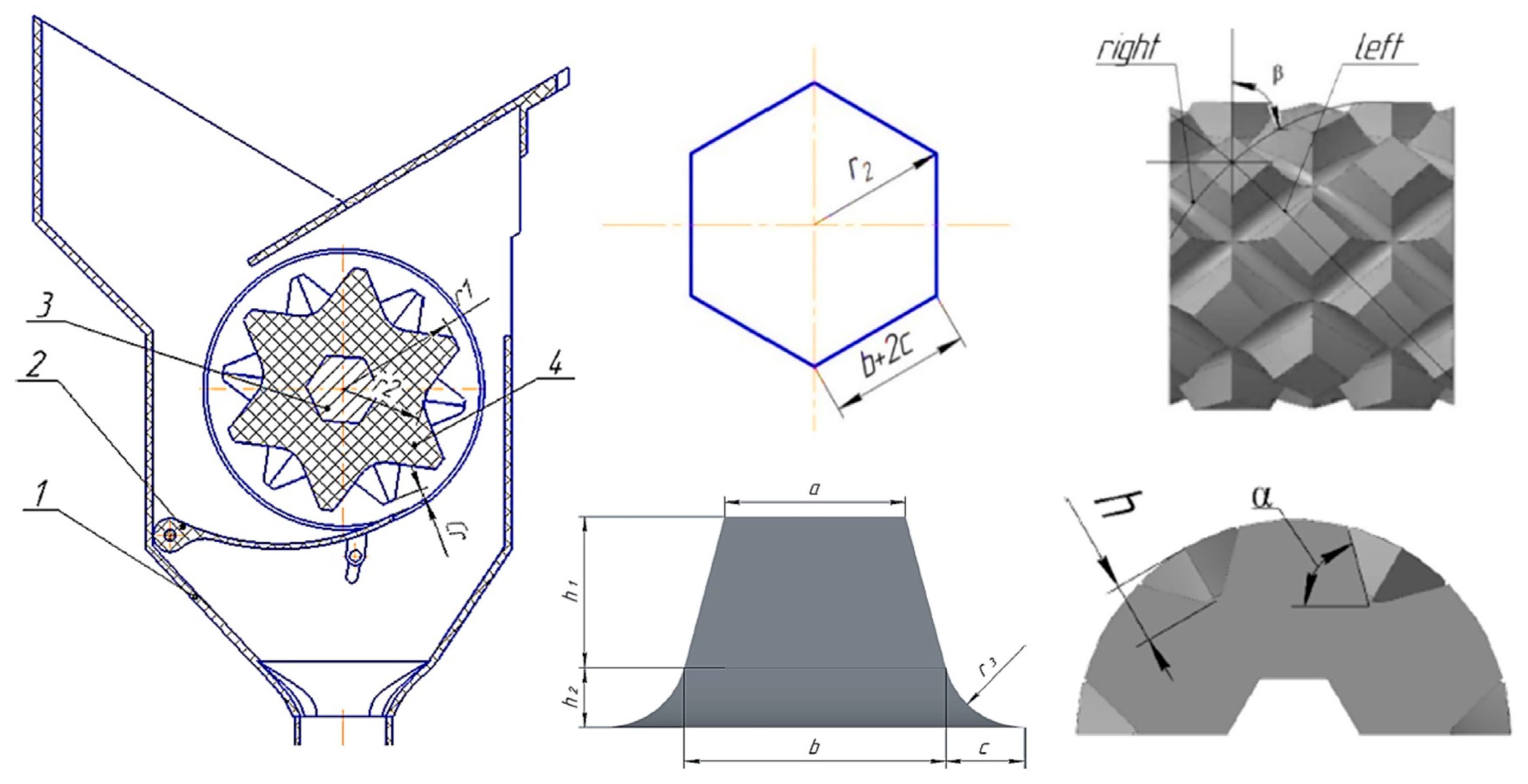
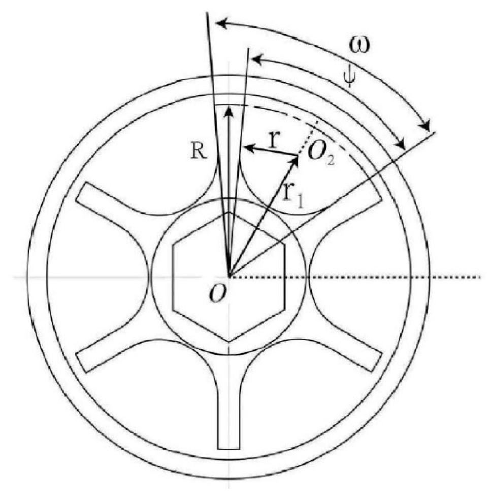
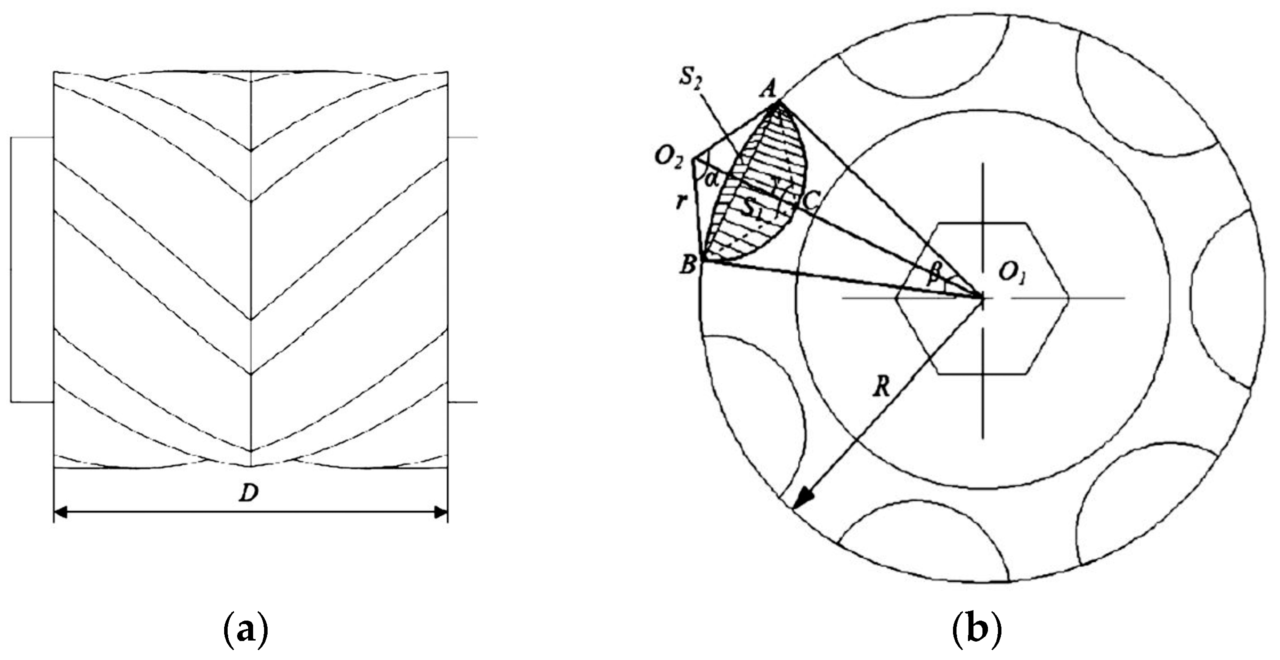
To investigate the impact of structural parameters of the groove wheel (as shown in
Figure 15) on fertilizer discharge performance, Liang Yuchao et al. [
27,
28] utilized polyurea as the test fertilizer to construct a model of the fertilizer filling and discharge process of the fertilizer discharger. Employing the discrete element software EDEM 2018, they analyzed fertilizer discharge performance under various groove wheel parameters, conducting single-factor tests on the fertilizer discharge quantity and multi-factor tests on the fertilizer discharge uniformity. The order of factors affecting fertilizer discharge performance is as follows: sheave radius, arc center distance, and number of grooves. The optimal structural parameters are determined as follows: an arc center distance of 25 mm, a sheave radius of 27 mm, and six grooves. Subsequently, bench tests and whole machine tests were carried out, yielding the fertilizer discharge uniformity coefficients ranging from 91% to 95%.
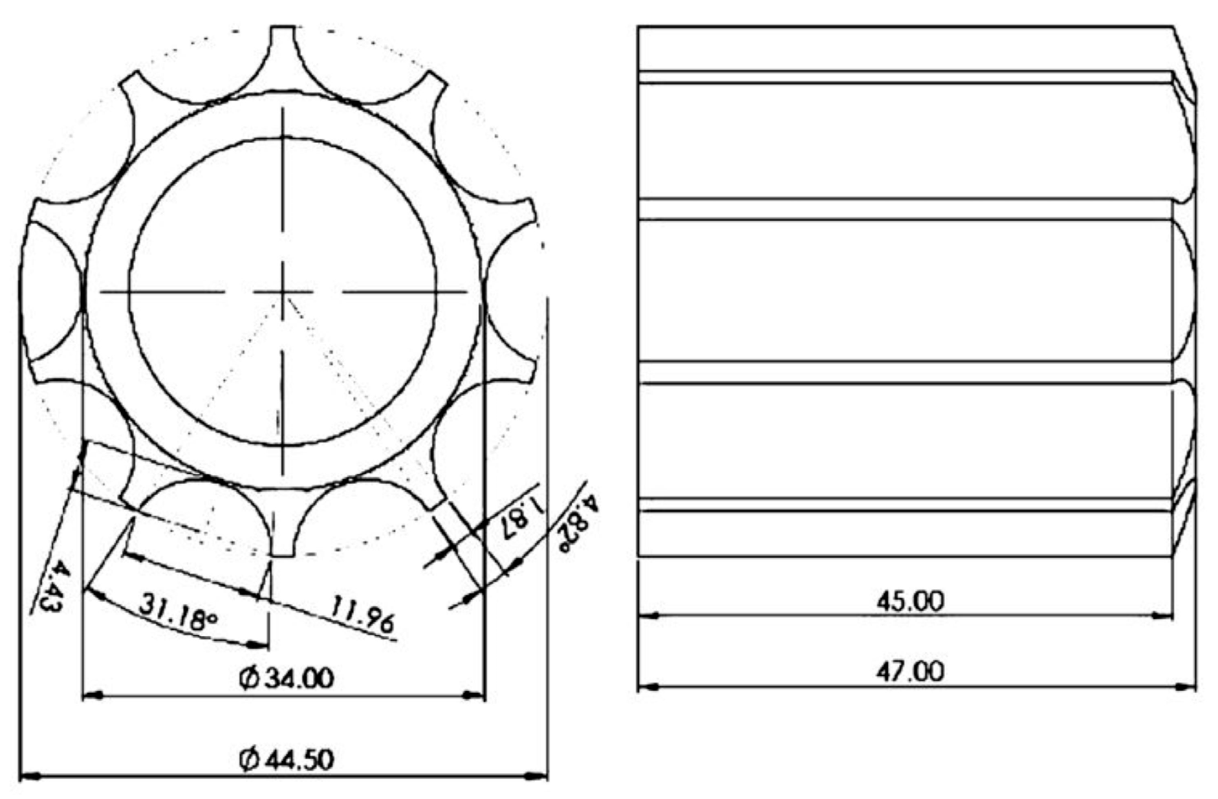
Based on theoretical analysis, Zhou Bin [
29] examined the fertilizer discharge process of the groove wheel fertilizer discharger through discrete element simulation. Its structure is depicted in
Figure 16. Single-factor and orthogonal experiments were devised to process the acquired data. The optimal parameter combination was a rotation speed of the groove wheel of 34.52 rpm, an effective working length of the groove wheel of 56.01 mm, and a depth of the sheave of 36.287 mm. Subsequently, in conjunction with bench testing, it was determined that the variation coefficient of the potassium fertilizer discharge amount was 8.68%, and the variation coefficient of the compound fertilizer discharge amount was 10.64%. The error between the simulated and actual fertilizer discharge amounts was less than 7%. The optimized fertilizer discharger exhibited superior performance in the jujube orchard.
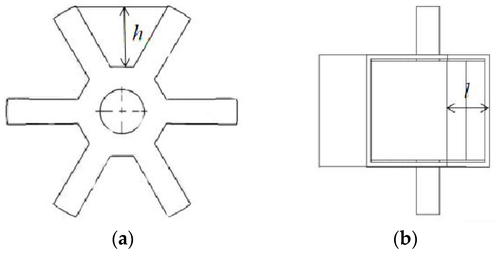
Yang Liu [
30] utilized discrete element software EDEM 4.0.0 to investigate the effects of the working length of the groove wheel, the angle of the lower fertilizer discharge tongue opening, and the rotation speed of the fertilizer discharge shaft on the movement trajectory of fertilizer particles. The structure is depicted in
Figure 17. Through single-factor and multi-factor indoor and field trials, it is concluded that the order and optimal parameter combination of factors affecting fertilizer discharge performance are as follows: ① Nitrogen fertilizer: a working length of the groove wheel of 40 mm, a fertilizer discharge shaft speed of 46 rpm, an angle of the lower fertilizer discharge tongue opening of 22.5 degrees, and a coefficient of variation of 3.48%. ② Phosphate fertilizer: a working length of the groove wheel of 42 mm, an angle of the lower fertilizer discharge tongue opening of 22.5 degrees, a rotation speed of the fertilizer discharge shaft of 48 rpm, and a coefficient of variation of 4.274%. ③ Potassium fertilizer: a fertilizer discharge shaft speed of 48 rpm, a working length of the groove wheel of 37 mm, an angle of the lower fertilizer discharge tongue opening of 22.5 degrees, and a coefficient of variation of 5.152%. The results all meet the national precision planting requirements.
To further enhance the precision of fertilizer discharge dosing from groove wheel fertilizer dischargers, Chinese researchers improved its structure by incorporating a spiral angle into the design, building upon the traditional right-angle fertilizer discharge groove wheel.
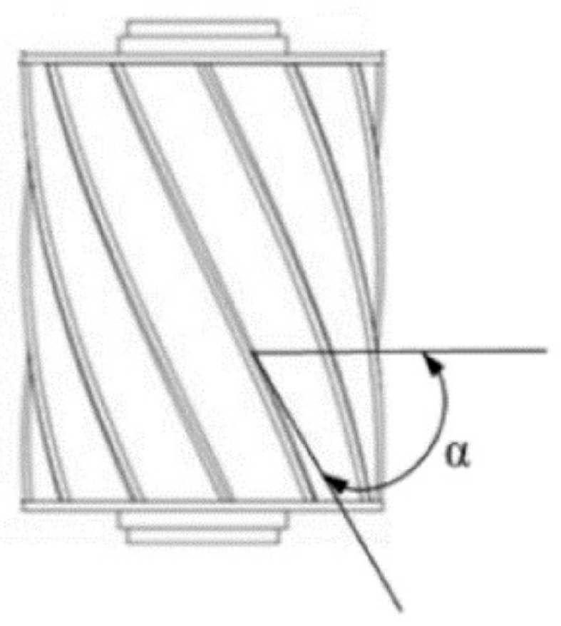
Song Xuefeng et al. [
31] devised a spiral groove wheel fertilizer discharger, and the structure of the groove wheel is depicted in
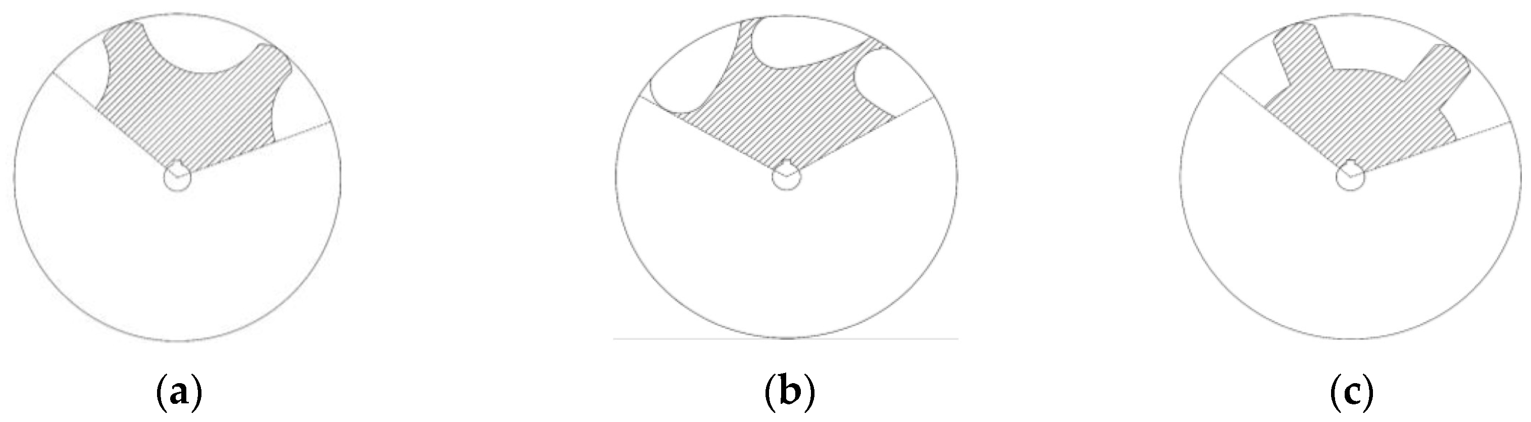
Figure 18. Based on the discrete element method, they simulated the movement of urea fertilizer and investigated the impact of parameters such as groove wheel rotating speed, helix angle, and cross-sectional shape (as shown in
Figure 19) on the fertilizer discharge performance. Employing a Box–Behnken three-factor and three-level test, the order of affecting factors is determined as follows: groove wheel speed, wheel cross-sectional shape, and spiral angle. Through thorough data analysis, they identified the optimal cross-sectional shape as scoop shape, and the parameter combination was as follows: a groove wheel rotating speed of 21 rpm and a helix angle of 70 degrees. Simulation tests and bench tests demonstrated that the variation coefficient of fertilizer discharge uniformity does not exceed 9.3%, and the error between simulation and measured data was less than 10%, effectively mitigating the fertilizer discharge blockage and enhancing the discharge accuracy.
Wang Yubing et al. [
32,
33] conducted a systematical investigation into the impact of fertilizer discharge uniformity, considering factors such as the rotation speed of the opposed, double-spiral groove wheel (as shown in
Figure 20), groove section radius, working length of the groove wheel, and spiral angle. Discrete element orthogonal experiments were employed to simulate the movement process of various fertilizers, including urea, compound fertilizer, and organic fertilizer. The optimal parameter combination was determined to be a rotation speed of 30 rpm, a groove section radius of 10 mm, a working length of the groove wheel of 50 mm, and a spiral angle of 45 degrees. Bench testing confirmed the reliability of the simulation with a deviation of only 0.91%. Field trials concluded that the coefficient of variation of fertilization uniformity was 10.13%, meeting the agronomic requirements for deep-side fertilization in tea gardens.
In addition, in order to make breakthroughs in the precise fertilizer discharge dosing from the groove wheel fertilizer discharger, Chinese researchers initiated studies on new designs for groove wheel fertilizer dischargers.
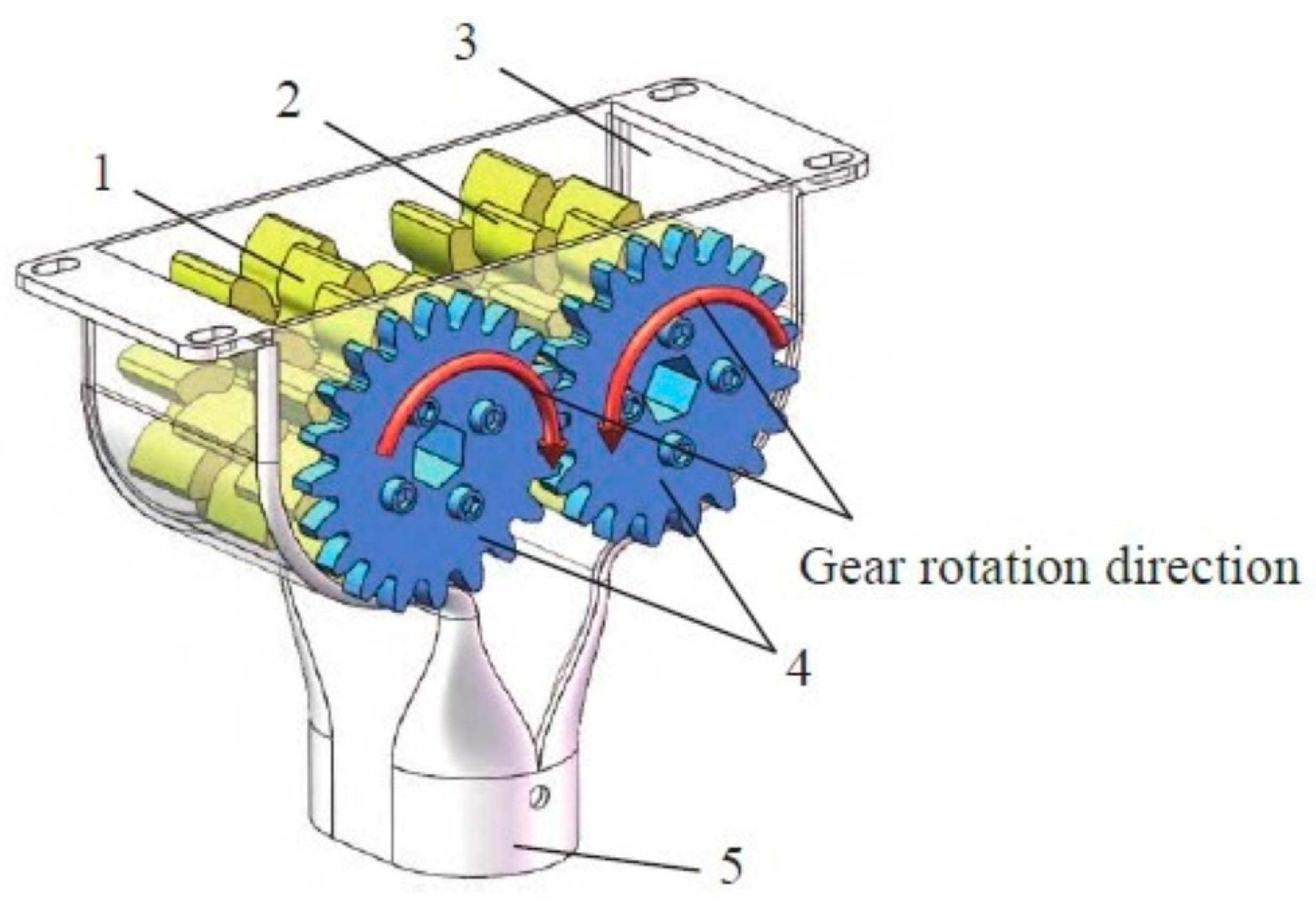
Dun Guoqiang et al. [
34] enhanced the design of a staggered gear fertilizer discharger based on spur-tooth fertilizer discharge gears, illustrated in
Figure 21. Based on theoretical analysis of the fertilizer discharge amount, they utilized the discrete element analysis method to simulate the discharge process of urea granules. Single-factor orthogonal simulation experiments were conducted to analyze the effects of parameters on the uniformity of fertilizer discharge. Results from simulations indicated that the number of staggered gear has a more significant impact on the discharge uniformity than the wheel clearance. Combining integrating simulation tests and bench tests, the best performance was attained by employing three staggered gear plates, with a wheel clearance set at 5 mm and a rotation speed of 60 rpm. This configuration yielded a coefficient of variation for the fertilizer discharge uniformity of no more than 4.8%, closely aligning with theoretical projections. The accuracy deviation of fertilizer amount was measured at 3.1%. The optimized fertilizer discharger exhibits excellent fertilizer uniformity and enables precise control of the fertilizer discharge.
The research above primarily focused on optimizing parameters such as groove wheel radius, arc center distance, number of grooves, groove cross-section radius, groove depth, effective working length, spiral angle, cross-sectional shape, rotation speed, angle of the lower fertilizer discharge tongue opening, number of staggered gears, and fertilizer wheel clearance through discrete element simulation, bench tests, field trials, and other research methodologies. It offers crucial theoretical and practical backing for achieving precise fertilization with groove wheel fertilizer dischargers and enhancing the stability and uniformity of fertilizer dosing.
2.3. Research Status of Disc Fertilizer Discharger
The working principle of disc fertilizer dischargers is as follows: fertilizer particles drop from the fertilizer box onto the fertilizer spreading disc. The fertilizer blades rotate around the axis, striking the fertilizer as they rotate at a certain speed, pushing the fertilizer toward the edge of the disc. The amount of fertilizer discharged can be adjusted by changing the rotation speed of the turntable and adjusting the height of the door. Finally, under the action of centrifugal force, the fertilizer is thrown out at a consistent speed. The structure of disc fertilizer dischargers includes a fertilizer-spreading disc, along with two or more fertilizer-spreading blades, as depicted in
Figure 22. This fertilizer discharger is primarily suitable for granular and powdered fertilizers, offering good looseness and fluidity. It features a simple structure, high operational efficiency, uniform fertilization, and minimal risk of fertilizer accumulation. Although widely utilized, it encounters challenges related to high resistance due to its structure [
35].
The work of international researchers focuses on studying the factors affecting the average spreading radius, the structure and working parameters of the fertilizer spreading disk, and the impact of the fertilizer discharge angle on the fertilizer discharge performance through simulation, bench testing, or developing new designs for disc fertilizer dischargers. They consistently optimize the parameters of fertilizer spreading discs to enhance the precision of fertilizer distribution.
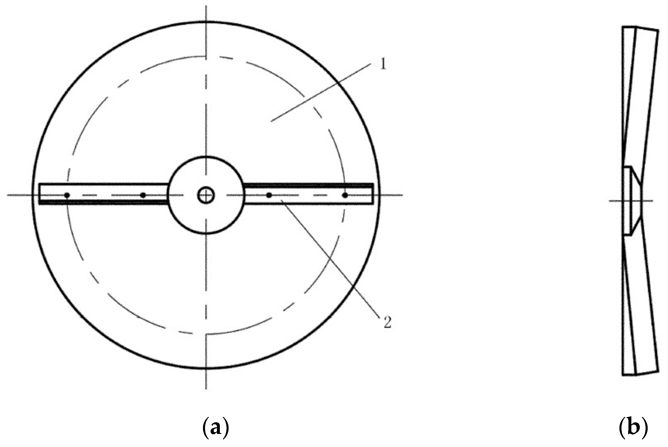
Przywara et al. [
36] conducted a bench test employing a four-factor experimental model to investigate the impact of parameter settings on the average radius of the disc fertilizer discharger. They analyzed the movement of three chemical fertilizers (urea, calcium ammonium nitrate, and ammonium sulfate) in discs with two different blade angles (as shown in
Figure 23). Model variance analysis revealed that fertilizer type, blade configuration, and disc angular velocity collectively contributed to 91.74% of the variance in the average diffusion radius. Furthermore, linear multiple regression analysis indicated that fertilizer dust fraction and disc angular velocity had an overall impact of 82.72% on the variance of the average diffusion radius. Notably, among the research findings, the negative correlation between fertilizer dust fraction and blade angular velocity was as high as 72.77%, offering valuable insights for future research endeavors.
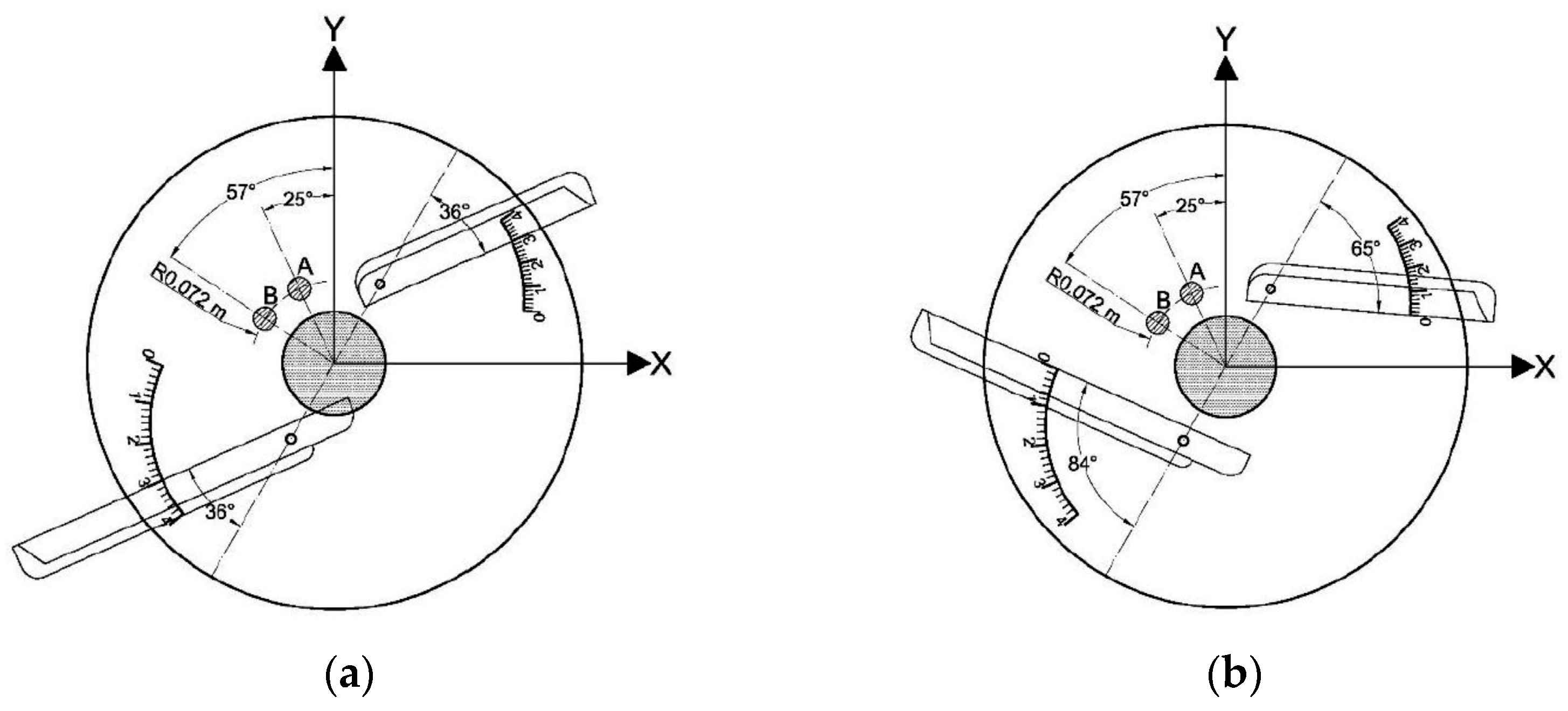
To enhance the uniformity and efficiency of fertilization, Bulgakov et al. [
37] devised a tilt-axis fertilizer discharger, depicted in
Figure 24. Field trials revealed that the rotation frequency of the disc exerts the most significant impact on the uneven distribution of fertilizers along the fertilization line in the tilt-axis fertilizer discharger. Adjusting the disc tilt angle and rotation frequency enables effective control of the fertilizer application width. Experimental findings demonstrate that increasing the rotation frequency from 600 to 800 rpm extends the effective fertilization range to 10.5 m while raising the inclination angle to 20 degrees expands the fertilizer spread range to 24 m. The tool exhibits an exponential upward trend in each operational mode, providing a foundation for selecting optimal parameters and operational techniques for fertilizer dischargers.
To address the issue of insufficient fertilizer uniformity during high-speed rotation of centrifugal fertilizer dischargers, Sidneva et al. [
38] used a spiral blade working mechanism to replace the straight blade, depicted in
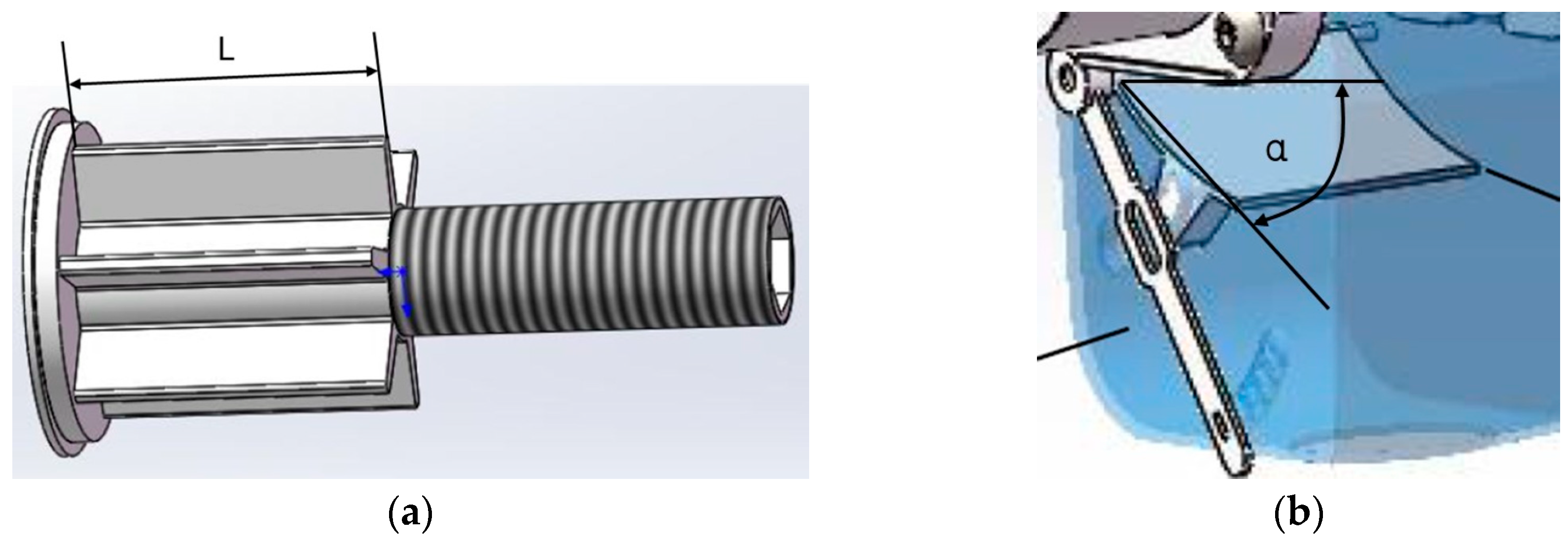
Figure 25. Experimental tests indicate that this innovation can enhance fertilizer distribution quality within the speed range of 4 to 16 kph. By adjusting the blade angle ranging from 0 to 20 degrees to optimize fertilizer dispersion, the developed fertilizer discharger can distribute fertilizers at higher speeds and more evenly across the field surface, with relevant parameters showing significant improvements over traditional devices.
The work of Chinese researchers primarily centers on the design and optimization of the structure and working parameters of fertilizer spreading discs. They employ a method that combines discrete element simulation with bench and prototype testing to continually optimize the parameters of the fertilizer spreading disk, aiming to improve the stability and uniformity of fertilizer distribution.
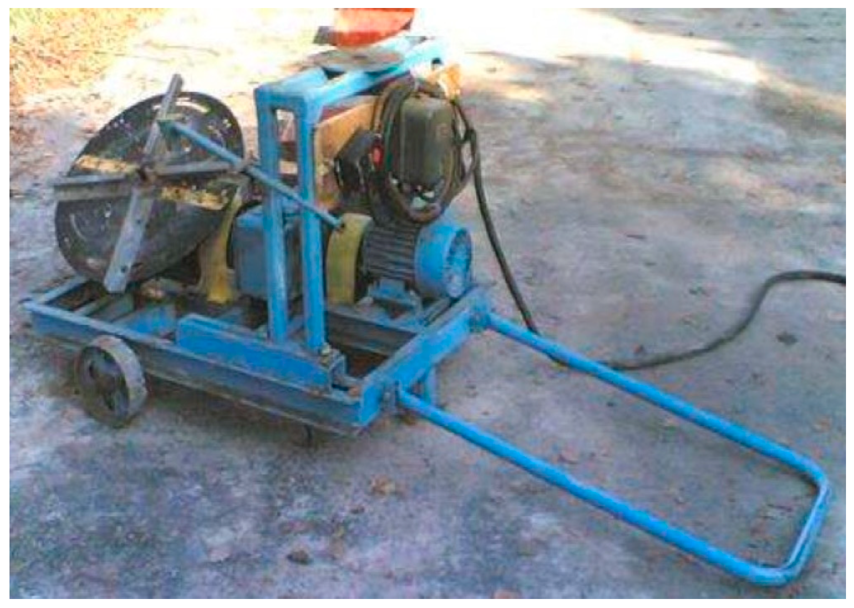
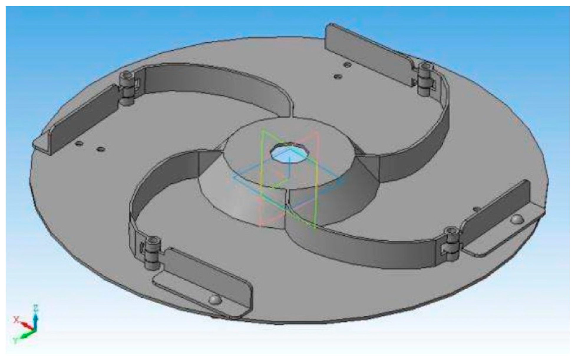
Yang Liwei et al. [
39] focused on the centrifugal disc fertilizer discharger as their research subject, depicted in
Figure 26. They conducted a prototype test to analyze the impact of key parameters on the uniformity of urea fertilizer spreading. Through a multi-factor response surface analysis test, they concluded that the order of factors affecting fertilizer spreading uniformity was as follows: feeding position angle, fertilizer spreading height, and blade position angle. By employing factor interaction response surface analysis, they determined the optimal parameter combination to be a fertilizer spreading height of 68.8 cm, a cutting position angle of 60 degrees, and a blade position angle of 29.63 degrees. With these settings, the coefficient of variation of fertilizer uniformity reached a minimum value of 9.95%, effectively resolving the issue of poor fertilizer discharge uniformity.
To achieve advancements in the precise distribution of fertilizers by disc fertilizer dischargers, Chinese researchers are dedicated to developing new designs for disc fertilizer dischargers. They utilize fertilizer discharge ejector pins and fertilizer scraping brushes to aid in the fertilizer discharge.
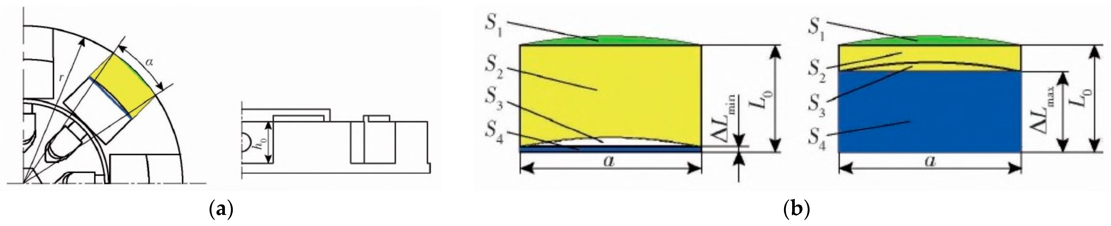
Shang Wenhu et al. [
40,
41] developed a disc ejection side-deep fertilizing device. The cross-section of the fertilizer trough is illustrated in
Figure 27. A kinematic model of the fertilizer discharge process was established and determined through discrete element simulation tests. The optimal working speed of the fertilizer discharge disc ranges from 10 to 60 rpm. Choosing the effective working length of the fertilizer trough as the test factor, results indicate that adjusting the effective working length of the fertilizer trough between 5 to 20 mm leads to a variation coefficient of fertilizer discharge uniformity ranging from 5.96% to 12.77%. Four special compound fertilizers with varying densities for side-deep fertilization of paddy fields were selected for testing. The device demonstrates good adaptability and meets national operating standards.
To further enhance the precision of fertilizer distribution from disc fertilizer dischargers, Chinese researchers additionally devised a fertilizer spreading disc featuring a conical blade shape and examined its structure and working parameters.
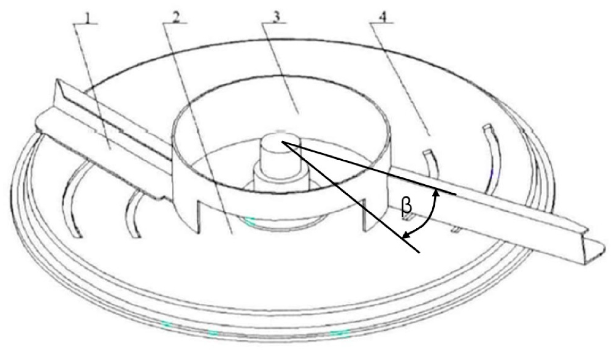
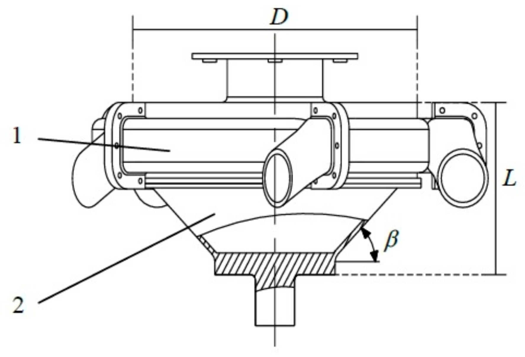
Fu Zuodong et al. [
42] devised a conical disc push plate double-row fertilizer discharger. The structure of the conical disc is depicted in
Figure 28. The impact of the number of push plates on fertilizer filling and discharge performance was analyzed through discrete element simulation. Findings reveal that with eight push plates, the fertilizer discharger exhibits optimal performance. Utilizing a full-factor bench test, it is observed that the fertilizer discharge amount has a strong linear correlation with both the conical turntable speed (ranging from 15 to 45 rpm) and the fertilizer discharge opening (ranging from 5 to 25 mm). The coefficients of variation for consistency of double-row fertilizer discharge, stability of total fertilizer discharge, and uniformity of fertilizer discharge vary from 1.01% to 3.88%, 1.05% to 3.81%, and 6.64% to 15.79%, respectively. When the device is tilted at 3 degrees, the maximum coefficient of variation for the consistency of fertilizer discharge in two rows is 6.17%. These test results align with the performance standards required for side-deep fertilization in paddy fields.
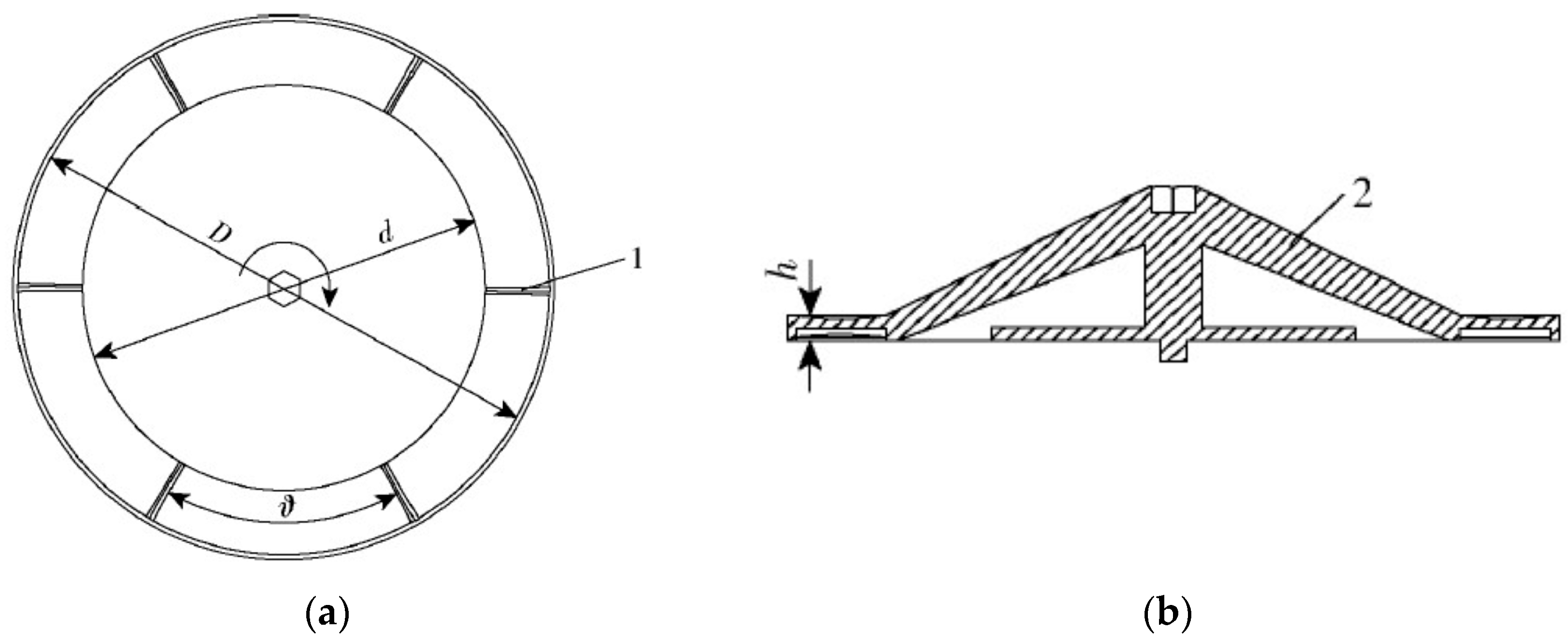
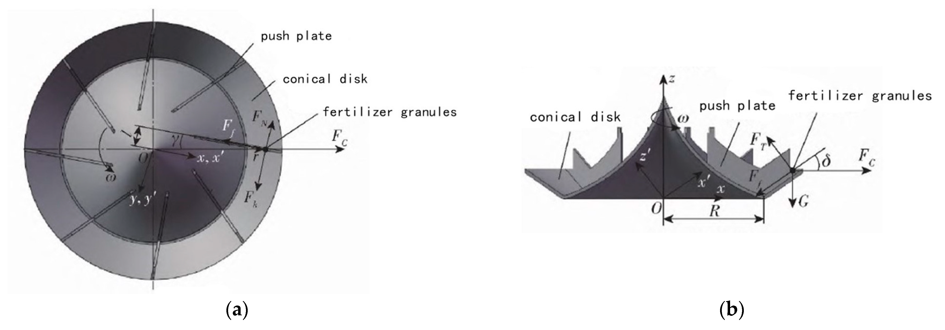
Liu Xiaodong et al. [
43,
44,
45] investigated the fertilizer discharge performance of the spiral cone centrifugal fertilizer discharger (depicted in
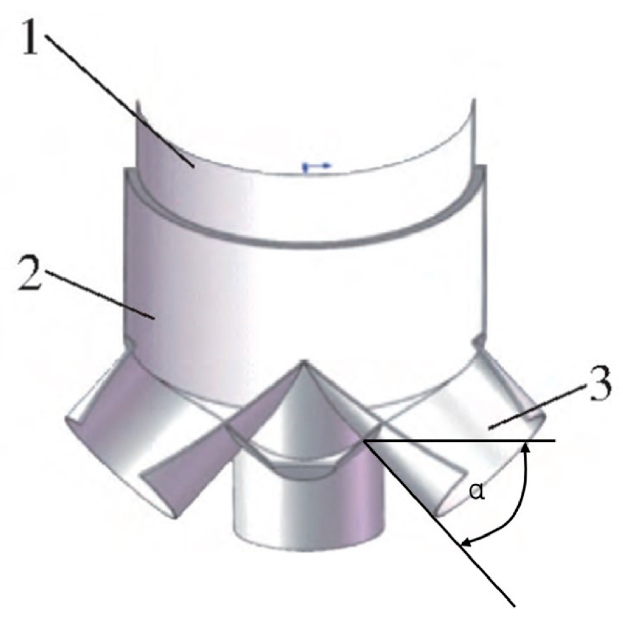
Figure 29) through discrete element simulation. The quadratic regression orthogonal rotation combination tests were employed to determine the optimal structural parameters: a horizontal inclination angle of 30.4 degrees, a push plate radial deflection angle of 3.2 degrees, and a cone disk speed of 130 rpm. Combined with bench and field trials, it was found that the stability variation coefficient of fertilizer discharge does not exceed 4.57%, thus meeting the standards for compound fertilizer fertilization in rapeseed fields.
In addition, in order to make breakthroughs in the precise fertilizer distribution from disc fertilizer dischargers, researchers initiated research on fertilizer dischargers that integrate a spiral fertilizer conveying device with a disc fertilizer discharger.
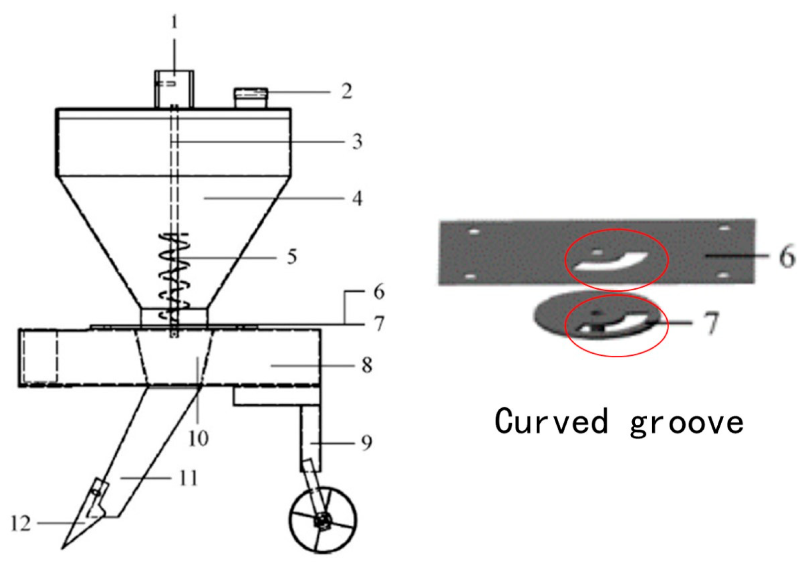
Song Shuaishuai et al. [
46] combined a vertical spiral fertilizer discharger to develop a disc variable fertilizer discharger tailored for banana orchard fertilization, as depicted in
Figure 30. They conducted discrete element simulation tests to determine the optimal fertilizer discharger parameters: a forward speed of 0.25 mps, a rotation period of 10 s, a central angle of 90 degrees, and a curved groove opening size of 20 mm. Field trials yielded an average fertilizer discharge qualification rate of 95.33%. The model and test errors, as well as the simulation and test errors of fertilizer discharge amount, are 11.15% and 6.68%, respectively. The fertilizer discharger demonstrates commendable operational performance.
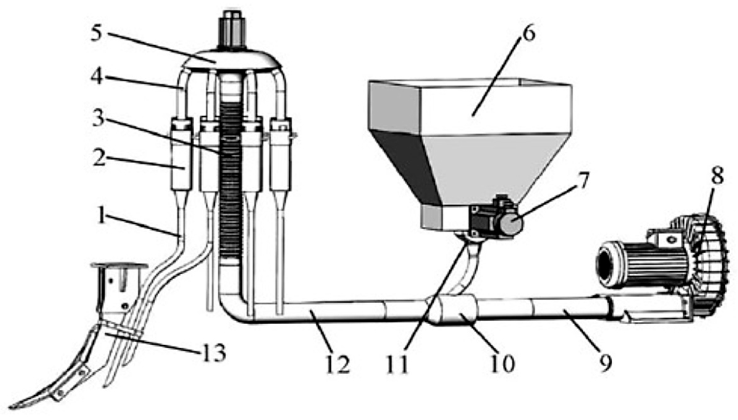
Cao Xin et al. [
47,
48] conducted a three-factor and two-level general rotation combination discrete element simulation test on a clustered, bidirectional spiral, fertilizer feeding, centrifugal conical disc fertilizer device, as illustrated in
Figure 31, to simulate the process of compound fertilizer discharge. The results indicate that the order of significance of factors affecting the variation coefficient of fertilizer uniformity is as follows: bidirectional spiral speed, conical disc speed, and traveling speed. The optimal parameter combination is determined to be a bidirectional spiral speed of 5.27 rpm, a conical disc speed of 243.7 rpm, and a device travel speed of 0.66 mps. Following optimization, the average coefficient of variation of fertilizer uniformity is 17.16%. The optimization and verification test results are highly consistent.
The above research primarily focused on optimizing parameters such as the angle of the fertilizer disc blades, the effective working length of the fertilizer groove, the size of the curved trough opening, rotation speed (angular velocity, frequency, period), fertilizer discharge opening, fertilizer spreading height, cutting position angle, disc inclination angle, and forward speed through discrete element simulation, bench, and field trials. These methods effectively enhanced the stability and uniformity of fertilizer distribution, offering a foundation and valuable references for further investigations into disc fertilizer dischargers.
2.4. Research Status of Air-Feed Fertilizer Discharger
The working principle of air-feed fertilizer dischargers is as follows: the fertilizer discharger utilizes a mechanical device for fertilizer supply, followed by fertilizer transportation through high-speed airflow. The gas–fertilizer mixture is thoroughly mixed in the mixing area via the high-speed airflow, and then the evenly mixed gas–fertilizer mixture is transported to the fertilizer discharge pipe. The structure is illustrated in
Figure 32. This method of fertilizer discharge enables a better flow of fertilizer, improved mixing performance, more stable fertilizer discharge, a simple overall structure, and enhanced efficiency in fertilization operations [
49].
The work of international researchers focuses on using fluid dynamics modeling and simulation and calculation methods in the fields of pneumatic seeders and agricultural fertilizer dischargers to examine whether fertilizer discharge meets the standards of precise fertilizer distribution.
Konovalov et al. [
50] established a linear calculation mathematical model of the pneumatic seeder system using MathCAD 8.0, as illustrated in
Figure 33. The system and design plan were detailed. Employing continuum mechanics, a parameter calculation method was proposed to validate the design decisions. By applying linear calculation to the series-parallel arrangement part, the linear calculation and structural indicators were redefined. The results indicate that the standard deviation of the air velocity within the section does not exceed 14%, and the standard deviation of the pressure on the section does not surpass 0.5%. The analytical model exhibited high accuracy, with a mass flow error of only 1.152 × 10
−14%.
Marcelo et al. [
51] utilized numerical simulation calculations and experimental comparisons, as depicted in
Figure 34, to validate the performance of two different types of radial fans in agricultural fertilizer dischargers at a rotation speed of 4000 rpm. Following the determination and validation of the mathematical model, the operational process of the fertilizer discharger was simulated, and the airflow distribution of the fertilizer discharger nozzle was assessed. Through experiments, it was observed that the numerical simulation yielded relatively accurate results, with an average error of 4.3%.
The work of international researchers centers on designing and optimizing the structure and working parameters of fertilizer distribution devices and air distribution devices of air-feed fertilizer dischargers. The Hertz theory, CFD fluid simulation, and CFD-DEM air-solid coupling analysis methods were employed to optimize the parameters of the fertilizer distribution device and air separation device, demonstrating improved stability in fertilizer distribution.
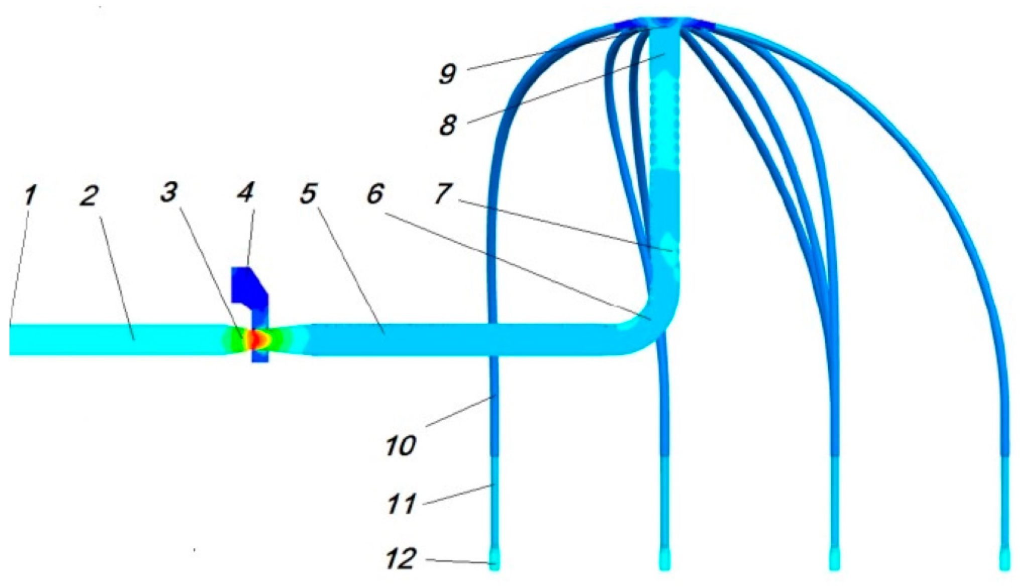
Wang Lei et al. [
52] investigated the air-feed fertilizer discharger system of an oil–wheat seeder. Based on the Hertz theory, they established an elastic collision model for fertilizer particles and distribution devices. Employing CFD and DEM air-solid coupling methods, they separately analyzed the movement of fertilizer particles and their impact on the fertilizer discharge performance across four types of distribution devices. The structure of the distribution device is depicted in
Figure 35. The findings reveal that the dome distribution device exhibits a superior fertilizer discharge performance, with the coefficient of variation of fertilizer discharge consistency in each row fluctuating between 6.35% and 7.52%.
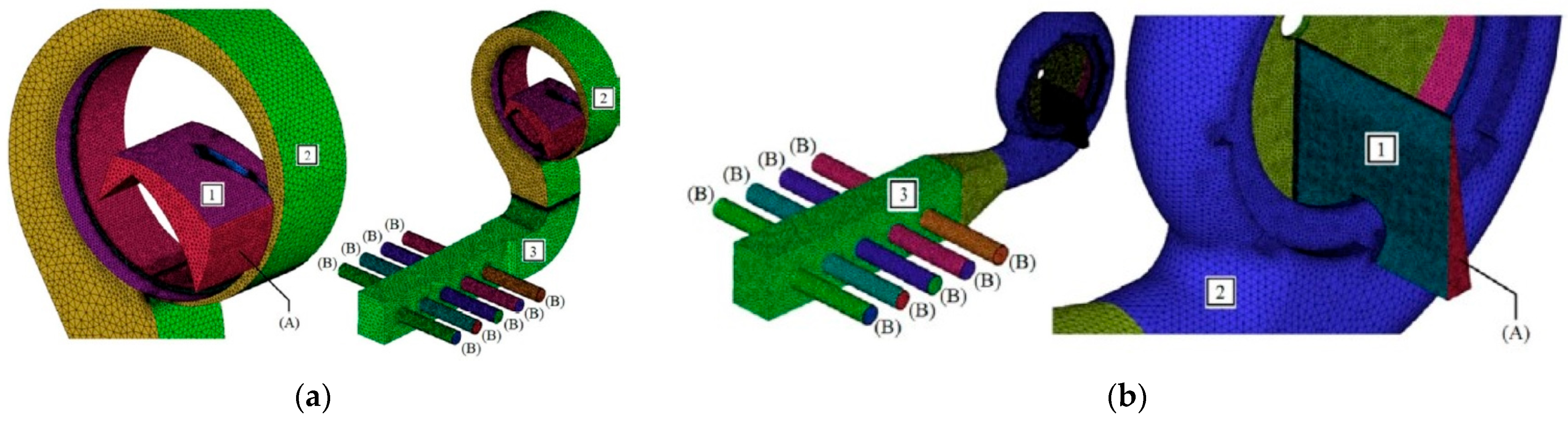
Jia Honglei et al. [
53] investigated a pneumatic centralized discharge precision mixing fertilization device for corn, integrating the research of CFD and DEM air-solid coupling methods. They utilized nitrogen, phosphorus, and potassium fertilizers as the test fertilizers and conducted a three-factor and two-level regression orthogonal combination design test. The optimized structural parameters are a fertilizer outlet inclination angle of 45 degrees, a conveying air speed of 35 mps, and a bellows length of 568 mm. The structure is depicted in
Figure 36 and
Figure 37. Subsequently, field trials were carried out, managing to control the error of fertilizer application within 2%, with a stability coefficient of variation of approximately 2%, meeting national standards.
Xu Zheng et al. [
54,
55] utilized CFD fluid simulation to enhance the performance of the air distribution device within the pneumatic fertilizer conveying system in rice fields. Its structure is depicted in
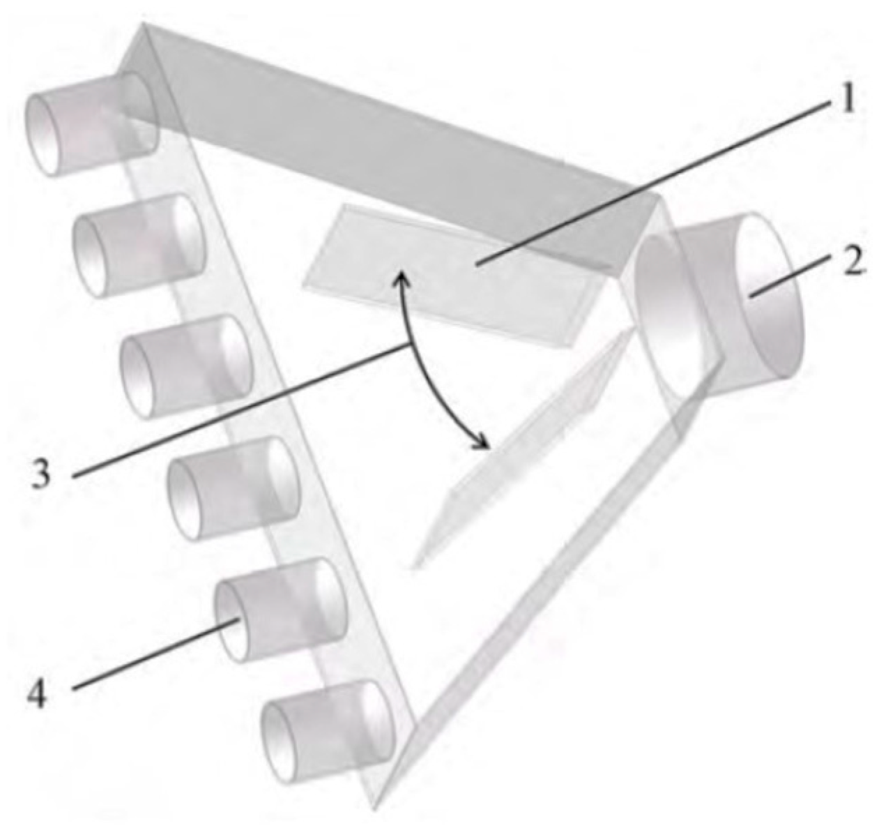
Figure 38. It is concluded that the opening angle of the baffle significantly affects the air separation performance, and at an opening angle of 48 degrees, the flow rate consistency of the exhaust port is optimal, with a fertilizer distribution variation coefficient of 5.65%. Concurrently, the connection method of the air–fertilizer mixing device was refined, with the feed pipe being connected and extended into the trachea at an inclined angle, thereby increasing the flow rate. Through the CFD-DEM air-solid coupling simulation test, it was observed that the optimized air–fertilizer mixing device increased the speed of urea particles by 93.6%.
The above research uses the Hertz theory, CFD fluid simulation, and CFD-DEM air-solid coupling analysis methods to compare and analyze various types of fertilizer distribution devices of air-fed fertilizer dischargers. The parameters such as the discharge outlet inclination angle, conveying air speed, bellows length, and opening angle of the air distribution device were optimized, effectively enhancing the precision of fertilizer distribution and reducing unevenness and breakage rates during fertilizer discharge, which has a reference value for future studies.


