Abstract
Short-circuit resistances are transformer parameters that characterize the electrical load losses and correct operation of these machines. However, the traditional concept of short-circuit resistance, independent of the harmonic frequencies, has been superseded by present transformer standards. Hence, new expressions for short-circuit resistances of three-phase transformers have been developed in this article based on the IEEE Standard C57.110-2018 and are presented jointly with the losses that these resistances characterize. These refer to the secondary effective short-circuit resistance of each phase (), of each harmonic (), and the non-fundamental frequency combined harmonics (). Likewise, the harmonic loss factor () has been established to determine the importance of the harmonics in each phase’s load losses. The application of these short-circuit resistances to the calculation of the load losses for a 630 kVA transformer from an actual residential distribution network has shown that the same values are obtained as with the IEEE Standard C57.110-2018, and they are 48.75% higher than those recorded with the traditional short-circuit resistances when the current distortion rates are 36.47%.
1. Introduction
Three-phase distribution transformers are the main devices that supply electrical power to homes, industries, and businesses. However, they waste energy during operation [1,2]. The magnitude of these energy losses determines the correct operation, efficiency, heating, and time life of transformers. Under full load conditions, at the industrial or fundamental frequency (50–60 Hz), the load losses () due to the circulation of currents through the windings are more significant [3,4] than the empty losses () caused by the electrical network supply voltages. The load losses of transformers in sinusoidal or slightly distorted networks, operating with load rates of 40 to 60%, are worth between 65% and 70% of the transformers’ total losses, depending on the manufacturer. In comparison, the no-load losses are 30–35%. However, the presence of harmonics in the winding currents, which are very common in distribution network transformers, usually increases the relative importance of load losses very significantly compared to no-load losses due to the low values of the voltage total harmonic distortion (), which are less than 5%, imposed by the regulations in these electrical networks [5].
The connection of non-linear loads, such as electronic converters for regulating electric motors, solar energy equipment, discharge lamps, and LEDs for lighting installations, constitutes the main cause of the presence of current harmonics in distribution transformers. However, unlike , there is no general limitation on the maximum value of the of the currents. Some associations of manufacturers of lamps, household appliances, and electronic converters encourage their members to limit the injection of harmonic currents from their devices. However, high values can be recorded in distribution networks. The article’s authors have managed to register values greater than 70% in highly distorted industrial distribution networks.
The load loss values () of three-phase distribution transformers can be obtained directly, by applying the IEEE Standard C57.110 [6,7,8,9,10,11,12,13,14,15,16,17] and other well-known standards [18,19,20,21,22,23,24,25,26,27,28,29,30,31,32], or, indirectly, based on their short-circuit resistances referred to as the secondary resistance (), according to the following expression:
where is the RMS value of the harmonic current of frequency , order of the secondary phases (), is the fundamental frequency (50–60 Hz), and is the order of the highest harmonic frequency used in the calculation.
Short-circuit resistances are, therefore, parameters that characterize transformers’ load losses. In industrial practice, the load losses of three-phase transformers have traditionally been calculated according to Equation (1), using the nominal value of the short-circuit resistance referred to as the secondary resistance (), which is obtained as follows:
according to the load losses () and secondary current () nominal values, determined after performing a short-circuit test at the industrial frequency (50–60 Hz) [33,34,35,36] or, by any of the procedures described in references [37,38,39,40,41,42,43,44]. The nominal short-circuit resistance () defined by Equation (2) is a parameter independent of the frequency of the winding current harmonics and has the same values in each phase of the three-phase transformers. However, its application in Equation (1) provides lower load loss values than those calculated with IEEE Standard C57.110-2018 [6] when the loads are non-linear.
This fact is explained because Equation (2) does not include the effects of skin phenomena and eddy currents induced in other metallic parts of the transformer, defined by IEEE Standard C57.110-2018, for harmonic currents of non-fundamental frequency.
To avoid the errors that usually introduces in the calculation of load losses of three-phase transformers, two types of short-circuit resistances were developed in [45,46], based on the expressions of the load losses included in the IEEE Standard C57.110-2018 [6,7], which have been included in Section 1.1. These are the short-circuit resistances of L. Sima et al. () [45] and the effective short-circuit resistances of each phase () [46], and their expressions are indicated in Section 1.2 of this article. However, the short-circuit resistance of L. Sima et al. is inappropriate, since its application determines values of the load losses that are different in each transformer’s phases than those obtained from the IEEE Standard C57.110-2018, as was verified in reference [46]; therefore, L. Sima et al.’s short-circuit resistance is not the object of study of this work.
The article’s main objective is to study the effects of the harmonics of the winding currents on the load losses of three-phase transformers, using their short-circuit resistances referred to each secondary phase of the transformer. To this end, Section 2 of the article develops the following novelties in the technical literature:
- The expressions of the short-circuit resistances specific to each harmonic () according to IEEE Standard C57.110-2018, and their condition as characteristic parameters of each transformer;
- The expressions of the effective short-circuit resistances of each phase () as a function of those of each harmonic ();
- The expressions for the combined effective short-circuit resistances of all non-fundamental frequency harmonics () as a function of and the short-circuit resistances inherent to the fundamental frequency harmonics of each phase ();
- The phase load losses (, , ) characterized by these short-circuit resistances;
- The harmonic loss factors of each phase (), which are the parameters that determine the relative importance of the load losses caused by the non-fundamental harmonic currents in each phase of the three-phase transformers.
In the Section 3 of the article (Results), the values of the short-circuit resistances calculated for the 630 kVA Dyn11 distribution transformer, immersed in oil, of an actual residential network are used to calculate the load losses and the harmonic loss factors of each phase of that transformer, using the measurements made by a Fluke 435 Series II analyzer at 6:55 a.m. and 8:55 p.m. on 10 November 2022. Furthermore, in this section, it is verified that the values of the load losses calculated with the short-circuit resistances developed in Section 2 are the same as those obtained with IEEE Standard C57.110-2018.
In the Section 4 (Discussion), the values of the load losses calculated every hour on 10 November 2022, using the short-circuit resistances of our approach, based on the IEEE Standard C57.110-2018, are compared with the obtained with the use of the nominal short-circuit resistance () of the traditional method. As a result of the comparison, it is found that the traditional procedure underestimates the effect of harmonics in determining load losses. Finally, in the article’s Section 5, the main conclusions are summarized.
1.1. Load Losses According to the Institute of Electric and Electronics Engineers (IEEE) Standard C57.110-2018
IEEE Standard C57.110 establishes that the following three power phenomena affect the value of load losses () of three-phase transformers: the resistance of the material of the windings, in direct current (), the Skin effect () and the phenomenon of electromagnetic induction in other metallic parts of the transformer other than the core (), which satisfy the following equation:
In the previous equation, direct current losses () are constant. In contrast, the phenomena that cause alternating current losses () depend on the frequencies () or the order () of the harmonic currents, with being the fundamental frequency.
Substituting the expressions of the load loss components () included in the standard in Equation (3), the total load losses of the three-phase transformers can be expressed as follows:
where , , and are the load losses corresponding to the three phenomena defined by IEEE Standard C57.110-2018, for the nominal conditions and at the fundamental frequency (). These losses satisfy the following equation:
where are the nominal load losses of the transformer, provided by the manufacturer in their catalogs or obtained after carrying out a nominal short-circuit test. The losses can be obtained through a direct current test [47] and the individual values of and are defined by the IEEE Standard C57.90TM [48], which sets, in oil-immersed transformers, and, in dry-type transformers.
Equation (4) is not explicitly expressed in IEEE Standard C57.110-2018, although it is used in many references [8,9,10,11,12] to refer to primary currents. However, the standard does not clearly indicate the meaning of the currents in Equation (4). That standard only establishes that is the RMS value of transformers’ nominal secondary currents and are the RMS values of the harmonic secondary currents of order h.
To clarify Equation (4), in [7], Equation (4) was adapted to indicate the meaning of the currents and used in IEEE Standard C57.110-2018. For Equation (4), to provide the values of the total load losses of the three-phase transformers, and must be, respectively, the combined RMS values of the harmonics and nominal currents of the three phases () of the secondary current, as follows:
The substitution of Expressions (6) in Equation (4) determines the following expression of the total load losses of the three-phase transformers, as follows:
where is the RMS value of the harmonic current of order of each phase () of the secondary current of the transformer, and is the nominal value of the secondary currents.
The values of the total load losses () obtained with this last expression are the same as those resulting from applying Equation (4), with the advantage that, in Equation (5), the load losses of each phase of the transformer () are directly differentiated, as follows:
The separation of the load losses of each phase indicated by Equation (8) is not so evident from Equation (4).
1.2. Short-Circuit Resistances of Three-Phase Transformers According to the Institute of Electric and Electronics Engineers (IEEE) Standard C57.110-2018
Short-circuit resistances are the parameters that characterize the transformers’ load losses, because its product times the square of the currents determines the value of those losses. L. Sima et al. developed, in [45], a short-circuit resistance, referred to as the primary resistance, that determines the transformers’ load losses established by IEEE Standard C57.110-2018. The short-circuit resistance of L. Sima et al., referred to as the secondary resistance, is expressed as follows [45]:
where are the total load losses of the transformer obtained with Equation (4), and is the combined RMS value of the currents of the three phases of the secondary winding, i.e., .
As the load losses established by IEEE Standard C57.110-2018 contain terms that are affected by the frequencies or the order of the harmonic currents, as observed in Equations (4) and (7), the short-circuit resistances also depend on the harmonic frequencies. This is an important difference compared to traditional short-circuit resistance (), which is independent of the frequencies of harmonic currents. For this reason, the short-circuit resistances of L. Sima et al. () usually have greater values than the nominal short-circuit resistances ().
However, the short-circuit resistances of L. Sima et al. have the same values in the three phases, since they are obtained based on the total load losses () and the combined currents of the three phases (). This is a remarkable drawback of these short-circuit resistances, which also happens with the traditional, because the phase load losses () calculated with have different values, in general, than those resulting from IEEE Standard C57.110-2018, applying Equation (8). That is, the short-circuit resistances of L. Sima et al. are not directly related and, therefore, do not characterize the load losses of each phase of three-phase transformers.
To avoid the drawbacks of the short-circuit resistance of L. Sima et al. and to correctly characterize the load losses of each phase of three-phase transformers according to IEEE Standard C57.110-2018, reference [46] developed the effective short-circuit resistances of each phase of the transformer (), as follows:
where is the load losses of each phase, defined by (8), and is the RMS value of the current of each secondary phase () of the transformer, as follows:
where is the RMS value of the harmonic current of order of each secondary phase () of the transformer, and is the order of the highest harmonic frequency used in the calculation.
The effective short-circuit resistances of each phase () have the following expressions, obtained after substituting Equations (8) and (11) into (10):
where the factors due to the skin () and other stray () losses of each phase [37] are calculated as follows:
and
are the nominal short-circuit resistances corresponding to the three phenomena defined by IEEE Standard C57.110-2018, namely the ohmic resistance of the coil conductors (), the resistance caused by the skin effect (), and the resistance caused by the currents induced in other metallic parts of the transformer (). The resistance is obtained in the direct current, while and are determined at the fundamental frequency (). The sum of these three resistances, shown below, is equal to the well-known nominal short-circuit resistance of the transformer (), traditionally used in industrial practice, which is defined by (2):
The effective short-circuit resistances of each phase () calculated according to Equation (12) generally have different values in each phase, and they are physical parameters of the three-phase transformers since they are related to the load losses of each phase, according to the following expression:
whose values match with those obtained according to (8), and the transformers’ total load losses are obtained as follows:
which satisfies Equations (4) and (7) deducted from IEEE Standard C57.110-2018.
2. Materials and Methods
In this section, the expressions of the short-circuit resistances for each harmonic of the secondary currents () and their relationships with the effective short-circuit resistances of each phase () are developed based on the expressions of the load losses of each phase () indicated in Section 1.1. Likewise, the specific expressions of the components of the effective short-circuit resistances of each phase () for the fundamental frequency () are combined with all of the non-fundamental frequency harmonics (), as well as the losses characterized by later short-circuit resistances ().
2.1. Short-Circuit Resistance and Load Losses of Each Harmonic
The circulation of a harmonic current of order and RMS value through the phase () of the secondary transformer causes the following losses:
where is the short-circuit resistance referred to as the secondary characteristic of the harmonic current of order .
The load losses in each phase () of the transformer must be equal to those caused by all the current harmonics of that phase, as follows:
Comparing the last expression with (8), the short-circuit resistance is expressed as follows:
From Expression (20), it follows that:
- (1)
- The short-circuit resistance of each phase harmonic current, referred to as the secondary current, , only depends on the order (or the frequency ) of the harmonic currents of each phase (), a difference in the resistances , which also depend on the RMS values of the currents, as deduced from Equations (12) and (13);
- (2)
- As it is usual that, in practice, the currents have harmonics of the same frequencies in the three phases (), the resistances of each harmonic, , are usually the same in the three phases of the transformer and, therefore, these resistances can be termed as and expressed, in general, as follows:
These properties give the short-circuit resistances of each harmonic () the status of characteristic parameters of three-phase transformers. For each transformer, the short-circuit resistances () of its order h harmonic currents always have the same values in the three phases, regardless of the load powered by the transformer.
2.2. Short-Circuit Resistance and Load Losses for the Fundamental Frequency and Combined of All Non-Fundamental Frequency Harmonics
Among all the short-circuit resistances of each harmonic (), the one corresponding to the fundamental frequency () stands out, because these harmonic currents transfer the useful active and reactive powers in power systems. The expression of the fundamental short-circuit resistance, based on Equation (21), is as follows:
This matches the nominal short-circuit resistance (), expressed by (15).
The short-circuit resistances characterize the phase load losses () as follows:
and characterize the total load losses () of the transformer caused by the fundamental frequency currents (), as follows:
The short-circuit resistances of non-fundamental frequency harmonics () increase considerably with the order (h), or with the frequency (), of each harmonic, as deduced from Equation (21). However, the effective short-circuit resistance of each phase () is usually only slightly higher than in practice. This shows that cannot be obtained as the sum of the short-circuit resistances of each harmonic ().
However, the resistances are related and can be obtained based on the short-circuit resistances of the harmonics. Equating Equations (16) and (19), the general relationship between the effective short-circuit resistances of each phase and the short-circuit resistances of the harmonics is deduced as follows:
where is the RMS value of the secondary currents of each phase () of the transformer, expressed by (11).
From the previous equation, the effective short-circuit resistance combined of all non-fundamental frequency harmonics () is defined in each phase as follows:
These resistances generally have a different value in each phase and characterize the values of the load losses caused in each phase by the set of all non-fundamental frequency harmonics, according to the following equation:
The transformer’s total load losses caused by the non-fundamental frequency harmonic currents are expressed as follows:
The load loss values calculated with Equation (28) coincide with those obtained with IEEE Standard C57.110-2018 for non-fundamental frequency currents, as follows:
This result shows that the effective short-circuit resistances, expressed by (26), characterize the load losses caused by the set of non-fundamental frequency currents.
2.3. Harmonic Loss Factor of Each Phase
For each transformer’s phase, the harmonic loss factor () is defined as the ratio, in percent, between the transformer’s load losses caused in that phase by the non-fundamental frequency harmonic currents () and the total current (), as follows:
This parameter determines the relative importance of the non-fundamental harmonics in the load losses of each phase of the transformer and, based on Equations (16) and (27), it can also be calculated as the ratio between the effective short-circuit resistances of non-fundamental frequency harmonics () and all harmonics () of each phase.
3. Results
This section analyzes the effects that harmonic currents caused on the load losses of the three-phase transformer of an actual residential distribution network in a village near Valencia (Spain). For this, the IEEE Standard C57.110-2018 was applied, as well as the different short-circuit resistances developed in Section 2 and the harmonic loss factor of each phase ().
The transformer is Dyn11, from the manufacturer Ormazabal, and its characteristics are summarized in Table 1. The values of the currents necessary for the analysis were obtained from the records made every hour on 10 November 2022, by a Fluke 435 Series II analyzer arranged at the secondary terminals.

Table 1.
Ratings of the 630 kVA distribution transformer provided by the manufacturer Ormazabal.
In this section, only the recordings made by the Fluke 435 Series II analyzer at 6:55 a.m. and 8:55 p.m. were used for the study. The first record (6:55 a.m.) corresponded to a time of low consumption, and the second record (8:55 p.m.) was carried out during a time of high consumption. The RMS values and distortion rates of the currents of each phase of the secondary currents () recorded by the Fluke analyzer are summarized in Table 2 for those two hourly periods. The RMS values of the secondary phase currents are indicated in more detail for the first 25 harmonics of these currents in Table 3.
Table 2.
RMS values () and total harmonic distortion () of the phase secondary currents recorded by the Fluke 435 Series II analyzer on two consumption periods on 10 November 2022.
Table 3.
RMS values () of the first 25 harmonic secondary currents, in amperes, recorded by the Fluke 435 Series II analyzer at 6:55 a.m. and 8:55 p.m. on 10 November 2022.
As the RMS values of the phase currents () indicate the homes’ consumptions, it can be deduced from Table 2 that the records made at 6:55 a.m. corresponded to a period of low consumption, and those obtained at 8:55 p.m. corresponded to high consumption. Therefore, based on the values of the distortion rates of the secondary currents () in Table 2, the loads fed through the transformer were strongly distorted in low consumption periods and weakly distorted in periods of high consumption.
3.1. Load Losses According to the Institute of Electric and Electronics Engineers (IEEE) Standard C57.110-2018
Table 4 shows the values of the total load losses () and in each phase () of the transformer, according to IEEE Standard C57.110-2018, calculated using Equations (7) and (8), respectively, based on the RMS values of the harmonic currents recorded in the secondary resistance of the transformer at 6:55 a.m. and 8:55 p.m. (Table 3). Likewise, Table 4 summarizes the values of the total load losses and of each phase for the harmonics of fundamental frequency ( and) and non-fundamental frequency ( and), obtained using Equations (7) and (8) with and, respectively.
Table 4.
Transformer’s load losses according to IEEE Standard C57.110-2018 at 6:55 a.m. and 8:55 p.m. on 10 November 2022.
3.2. Short-Circuit Resistances and Load Losses for Each Phase Harmonic Current
Table 5 summarizes the values of the short-circuit resistances , calculated using Equation (20) for the first 25 harmonics of the secondary currents at 6:55 a.m. and 8:55 p.m. (Table 3), using the values of the nominal short-circuit resistances,, obtained by substituting the nominal values of the transformer losses, indicated in Table 1, on Equation (14).
Table 5.
Transformer’s short-circuit resistances () and phase () and total () load losses for the first 25 harmonic currents at 6:55 a.m. (a low consumption period) and at 8:55 p.m. (a high consumption period) on 10 November 2022.
Likewise, Table 5 shows the values of the losses corresponding to each harmonic () and each phase (), obtained with the use of the values of the short-circuit resistances in Equations (18) and (19), respectively.
From the results indicated in Table 5, the following findings about the short-circuit resistances of each harmonic () are verified:
- (1)
- They are characteristic parameters of each transformer, since they have the same values for each frequency, regardless of the load consumptions;
- (2)
- Their values increase strongly with the frequencies of the harmonics of the currents;
- (3)
- They identify the losses caused by harmonic currents in each phase (), since the sum of losses obtained with the short-circuit resistances () determine the same values of total () and phase () load losses, and their components for the fundamental () and non-fundamental () frequencies than those resulting from applying IEEE Standard C57.110-2018, indicated in Table 4.
3.3. Short-Circuit Resistances and Load Losses of Each Phase at the Fundamental and Non-Fundamental Frequencies
Table 6 summarizes the values of the effective short-circuit resistances () and the load losses () of each phase for the two analyzed consumption periods (6:55 a.m. and 8:55 p.m.). The values of have been obtained by substituting into Equation (25) the RMS values of the currents of each phase () and each harmonic (), indicated in Table 2 and Table 3, respectively, as well as the short-circuit resistances of each harmonic (), shown in Table 5. The values of the load losses of each phase () have been obtained by substituting into Equation (16) the values of from Table 7 and the RMS values of the secondary phase currents () from Table 2.
Table 6.
Transformer’s effective short-circuit resistances () and load losses () of each phase at 6:55 a.m. and 8:55 p.m. on 10 November 2022.
Table 7.
Transformer’s short-circuit resistances () and phase () and total () load losses for the non-fundamental harmonic currents at 6:55 a.m. and 8:55 p.m. on 10 November 2022.
The values of the short-circuit resistance () and the load losses of each phase () and total () for the fundamental frequency are those indicated in Table 5 for the harmonic of order. It is noted in these tables that the fundamental frequency short-circuit resistance has the same value,, in the three phases of the transformer for the two analyzed consumption periods (6:55 a.m. and 8:55 p.m.).
The values of the combined short-circuit resistances of all non-fundamental frequency harmonics of each phase () and the values of the losses in each phase () and total () that these resistances characterize are obtained by applying Equations (26) and (27), respectively, and are summarized in Table 7.
- (1)
- Equation (25) is suitable for calculating the effective short-circuit resistances of each phase () from the individual resistances of the harmonics (), since the product of the short-circuit resistances obtained with that equation determines the same load loss values in each phase () as the IEEE Standard C57.110-2018, indicated in Table 4 for the two consumption periods.
- (2)
- The effective short-circuit resistances of each phase () are not equal to the sum of the short-circuit resistances of the harmonics of that phase (), as can be seen in Table 5, due to the high values that the resistances acquire as the order h of the current harmonics increases.
- (3)
3.4. Relative Importance of Non-Fundamental Frequency Harmonics in Transformer Load Losses
The values of the load losses of each phase of the transformer indicated in Table 6 and Table 7 indicate that the losses caused by non-fundamental frequency harmonics are relatively more important during low-consumption hours (6:55 a.m.) than during high-consumption hours (8:55 p.m.). The values of each phase harmonic loss factor () presented in Table 8 confirm this fact.
Table 8.
Relative importance (), in percent, of current harmonics in the transformer load losses at 6:55 a.m. and 8:55 p.m. on 10 November 2022.
Based on these values of the harmonic loss factor (), it follows that the below statements are true:
- (1)
- There are important non-linear loads powered by the transformer at 6:55 a.m., highlighting those connected to the C-phase, which give rise to load losses of 55.57% of the total load losses in that phase exclusively caused by non-fundamental frequency harmonics. Due to the small consumptions of homes at that time, the high current distortion, greater than 30% (Table 2), should be attributed mainly to public lighting.
- (2)
- The loads operating in homes at 8:55 p.m. are slightly distorted and mitigate the strong distortion of currents caused by public lighting lamps. This fact is proven by the significant reduction in the harmonic loss factor () in the three phases of the transformer (Table 8), reaching 8.16% in the C-phase.
- (3)
- The minor reduction in the loss factor in phase B is due to the small consumptions of the homes connected to that phase of the transformer rather than in the other two phases.
Following the previous conclusions, it is noted that the harmonic loss factor () can be a more suitable indicator than the total harmonic distortion of currents () for knowing the energy effects of non-linear loads on distribution transformers.
4. Discussion
The values of the traditional load losses calculated on the transformer of the residential distribution network in Section 3 using the nominal short-circuit resistance () are compared in this section with those load losses obtained using the new short-circuit resistances developed in Section 2 on 10 November 2022.
Table 9 summarizes the RMS values of the currents in each secondary phase of the transformer (), their fundamental frequency components (), and the total harmonic distortion () of these currents. Except in specific cases, it is observed that the distortion rates usually have high values when household consumptions are low. This fact is noted during the early morning hours and can be attributed mainly to public lighting. The high rates of distortion of the currents occasionally observed in some phases during the afternoons (4:55 p.m.) are due to the use of fluorescent lighting and refrigerators in shops.
Table 9.
Total harmonic distortion and RMS values of total and fundamental frequency secondary phase currents recorded by the Fluke 435 Series II analyzer on 10 November 2022.
The values of the nominal short-circuit resistance (), as well as the effective short-circuit resistances of each phase () and due to all non-fundamental frequency harmonic () are summarized in Table 10. The resistances and have been calculated using Equations (25) and (26), respectively, while the value of has been determined using either Equation (2) or (22).
Table 10.
Phase short-circuit resistances of the transformer, in mΩ, on 10 November 2022.
From Table 10, it is noted that the following are true:
- (1)
- The nominal short-circuit resistance () has the same value in the three phases of the transformer and is independent of the distortion rates of the currents since, according to (22), it coincides with the short-circuit resistance for the fundamental frequency ().
- (2)
- The effective short-circuit resistances of each phase () and combined non-fundamental frequency harmonics () have different values in each phase, which increase with the distortion rate of the currents of each phase.
- (3)
- The values of traditional short-circuit resistances () are always less than , since they do not include the effects of non-fundamental frequency harmonics.
The transformer’s load losses according to the traditional procedure (), indicated in Table 11, have been obtained in each phase by multiplying their nominal short-circuit resistance (, Table 10) by the squares of the RMS values of the phase currents (, Table 9).
Table 11.
Load losses according to traditional methods and based on IEEE Standard C57.110-2018 short-circuit resistances ( and ), respectively, and relative differences on 10 November 2022.
Likewise, Table 11 summarizes the values of the load losses of each phase of the transformer (), obtained according to Equation (16), using the values of indicated in Table 10 and the RMS values of the currents of each phase of the secondary resistance in Table 9. These losses coincide with those deduced from the application of the IEEE Standard C57.110-2018, as verified in Section 3. The relative differences between these losses () and the traditional ones are indicated in Table 11 on 10 November 2022.
Table 12 summarizes the values of the load losses of each phase of the transformer due to the exclusive effect of non-fundamental frequency harmonics using the traditional procedure () and based on IEEE Standard C57.110-2018 (). The values of the non-fundamental frequency load losses with the traditional procedure are obtained as the following difference: , in which the values of are stated in Table 11 and the load losses for the fundamental frequency () are obtained from Equation (23). The values of the load losses due to non-fundamental frequency harmonics based on IEEE Standard C57.110-2018 () have been calculated with Equation (27), using the values of and shown in Table 9 and Table 10, respectively.
Table 12.
Load losses due to the non-fundamental currents according to traditional methods and based on IEEE Standard C57.110-2018 procedures, respectively, and relative differences on 10 November 2022.
- (1)
- The load losses calculated based on IEEE Standard C57.110-2018, using the effective short-circuit resistances of each phase (), always have higher values than those obtained with the traditional procedure in industrial practice, using the nominal short-circuit resistance ().
- (2)
- The comparison of both procedures shows relative differences in the values of load losses in phase C of the transformer of up to 48.75%, obtained at 6:55 a.m. on 10 November 2022 (Table 11).
- (3)
- The combined effective short-circuit resistances of the harmonics () faithfully characterize the load losses caused by all harmonics of non-fundamental frequency, since the product determines the same values (, Table 12) as those obtained according to IEEE Standard C57.110-2018 by subtracting .
- (4)
- The values of load losses due to the exclusive effect of harmonics calculated based on IEEE Standard C57.110-2018 () are always much higher (Table 12) than those calculated with the traditional method ().
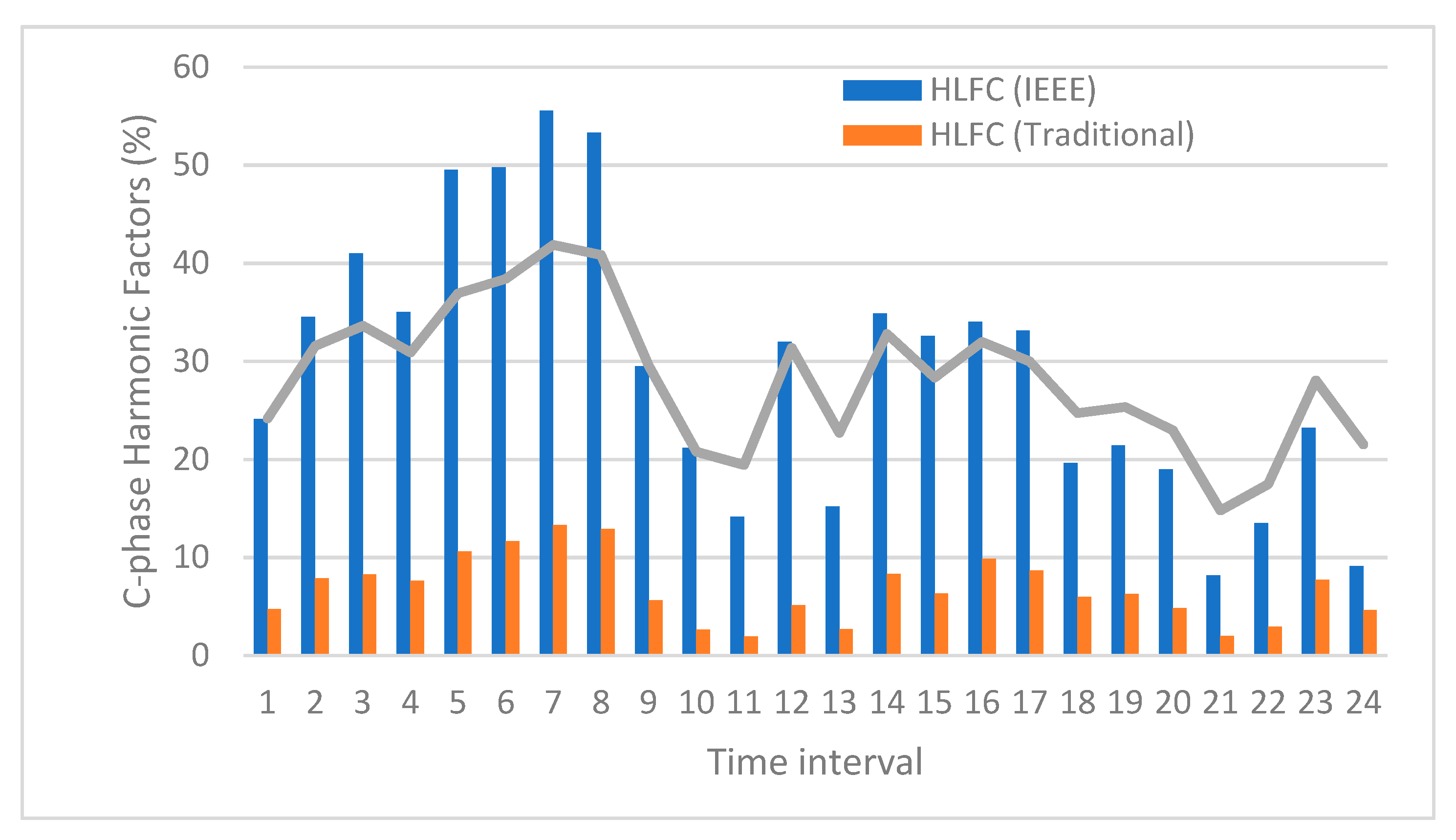
The traditional method underestimates the effects of harmonics on load losses compared to the procedure based on IEEE Standard C57.110-2018. This is observed in Figure 1, Figure 2 and Figure 3, which represent the harmonic loss factors () of phases A, B, and C, respectively, obtained throughout 10 November 2022, applying Equation (30), using the load loss values determined by IEEE Standard C57.110-2018 and the traditional method, respectively. In these figures, the following statements are verified:
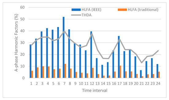
Figure 1.
Transformer’s A-phase harmonic loss factor () based on IEEE Standard C57.110-2018 and traditional procedures, and A-phase total harmonic distortion () on 10 November 2022.
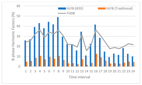
Figure 2.
Transformer’s B-phase harmonic loss factor () based on IEEE Standard C57.110-2018 and traditional procedures, and A-phase total harmonic distortion () on 10 November 2022.
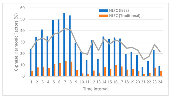
Figure 3.
Transformer’s C-phase harmonic loss factor () based on IEEE Standard C57.110-2018 and traditional procedures, and A-phase total harmonic distortion () on 10 November 2022.
- (1)
- The importance of non-fundamental harmonics in the load losses of each phase of the transformer, determined by the factor, is much greater using IEEE Standard C57.110-2018 than the traditional method. As an example, it is observed in Figure 3 that the load losses due to non-fundamental frequency harmonics calculated at 6:55 a.m. on 10 November 2022 (time interval No. 6) are 55.57% of the load losses in phase C, according to the Standard. However, these load losses only reach 13.3% of the load losses in phase C, using the traditional method.
- (2)
- The harmonic loss factors () in both procedures, the IEEE Standard C57.110-2018 and the traditional method, increase their values with the current distortion rates (), which, in this application example, usually coincide with the hours of lowest consumption in homes (Figure 1, Figure 2 and Figure 3).
- (3)
- Based on the information presented above, we can conclude that household loads are much less distorted than the rest of the loads connected to the residential distribution network. That is because in the hours of highest household consumption, the harmonic loss factors have their lowest values (Figure 1, Figure 2 and Figure 3).
5. Conclusions
The load losses of electrical transformers are of great practical interest since they allow monitoring to ensure correct operation and make it possible to carry out preventive maintenance, identifying possible causes of failures. One of these causes is current distortions, which increase the load loss values. In this article, the effects of current harmonics on the load loss values of three-phase distribution transformers are obtained indirectly using their short-circuit resistances, obtained according to IEEE Standard C.57.110-2018. Specifically, new expressions of the short-circuit resistances for each harmonic () are developed according to the standard. Based on those resistances, the expressions of the effective short-circuit resistances for each phase () and combinations of all non-fundamental harmonics () are established. These short-circuit resistances characterize load losses of three-phase transformers according to IEEE Standard C57.110-2018 and are a novelty in the technical literature. The harmonic loss factor of each phase () is another novelty of the article. This parameter determines the relative importance of non-fundamental harmonics in the load losses of each phase of the three-phase transformers.
The comparison of the load loss values obtained in the transformer of an actual residential distribution network with the use of these resistances and those resulting from applying the traditional procedure in industrial practice, using the nominal short-circuit resistance (), has allowed us to verify the following findings:
- The values of the new effective short-circuit resistances ( and) are usually different in the three phases of the transformer and vary with the frequencies and the RMS values of the harmonics of the currents, as happens with the phenomena associated with load losses in transformers. For this reason, these resistances are physical parameters of three-phase transformers, which accurately determine the total () and phase () load losses, as well as the load losses of the set of all non-fundamental harmonics ( and), providing exactly the same values as IEEE Standard C57.110-2018.
- Using the nominal short-circuit resistance (), which is traditional in industrial practice, is not advisable for correctly measuring load losses of transformers feeding non-linear loads. In the practical application of this article, it has been verified that the traditional procedure determines load loss values in the phases of up to 48.75% (6:55 a.m., phase C) lower than those calculated with the IEEE Standard C57.110-2018. This result is because the traditional procedure underestimates the losses caused by current harmonics of non-fundamental frequency, as deduced by comparing the values of the harmonic loss factor of each phase (). At that same time (6:55 a.m.), the value of this factor in phase C was only 13.3%, using the traditional procedure, as opposed to 55.57%, as measured in that phase by the IEEE Standard C57.110-2018.
- The previously indicated errors of the traditional procedure in measuring transformer load losses increase with current distortion rates () and are due to the inadequate definition of the nominal short-circuit resistance (), whose values are obtained for the fundamental frequency and under load balanced conditions and does not include the energy phenomena caused by non-fundamental frequency currents.
- From a strictly physical point of view, the explanation of how the new short-circuit resistances determine higher load losses than traditional short-circuit resistances is that the former incorporates the effects caused by skin and electromagnetic induction phenomena in other metallic parts of the transformer for all frequencies of current harmonics, both fundamental (50–60 Hz) and non-fundamental. In contrast, traditional short-circuit resistances only include the effects of skin and electromagnetic induction phenomena for the fundamental frequency harmonic current.
The study’s results are limited to using short-circuit resistances based on the IEEE Standard C57.110-2018 approach. The use of ANSI 1561 and 1562 Standards determined that short-circuit resistances of values are higher than traditional short-circuit resistances but lower than the new resistances established in this paper, since ANSI Standards consider electromagnetic induction phenomena to be negligible, contrary to the IEEE Standard C57.110-2018. The short-circuit resistances according to Standards IEEE and ANSI will be compared in future works.
Likewise, a future article is intended to extend the use of the new effective short-circuit resistances to preventive maintenance of three-phase transformers, with the development of novel factors that detect operating limitations and reductions in the lifetime of these machines, due to excess losses caused in their phases by harmonic currents.
6. Patents
This article was based on our patent P202330968—“Use of short-circuit resistances, procedure and device for monitoring the operating state of a three-phase transformer in service”—lodged with the Spanish Patent and Trademark Office (OEPM).
Author Contributions
Conceptualization, V.L.-M., E.P.-L. and J.Á.S.-J.; methodology, V.L.-M. and E.P.-L.; software, V.L.-M. and A.L.-V.; validation, V.L.-M., E.P.-L. and J.Á.S.-J.; formal analysis, V.L.-M., E.P.-L. and A.L.-V.; investigation, V.L.-M., E.P.-L., J.Á.S.-J. and A.L.-V.; resources, V.L.-M., E.P.-L. and J.Á.S.-J.; data curation, V.L.-M. and A.L.-V.; writing—original draft preparation, V.L.-M., E.P.-L., J.Á.S.-J. and A.L.-V.; writing—review and editing, V.L.-M., E.P.-L., J.Á.S.-J. and A.L.-V.; visualization, V.L.-M., E.P.-L., J.Á.S.-J. and A.L.-V.; supervision, V.L.-M.; project administration, V.L.-M. and E.P.-L.; funding acquisition, V.L.-M. and E.P.-L. All authors have read and agreed to the published version of the manuscript.
Funding
This research and APC was funded by the Generalitat Valenciana within the ValREM Project (CIAICO/2022/007).
Institutional Review Board Statement
Not applicable.
Informed Consent Statement
Not applicable.
Data Availability Statement
Data are contained within the article.
Conflicts of Interest
The authors declare no conflicts of interest. The funders had no role in the design of the study; in the collection, analyses, or interpretation of data; in the writing of the manuscript; or in the decision to publish the results.
References
- U4E. Accelerating the Global Adoption of Energy-Efficient Transformers; UN Environment, Economy Division, Energy & Climate Branch: Paris, France, 2017. [Google Scholar]
- Shareghi, M.; Phung, B.T.; Naderi, M.S.; Blackburn, T.R.; Ambikairajah, E. Effects of Current and Voltage Harmonics on Distribution Transformer Losses. In Proceedings of the IEEE International Conference on Condition Monitoring and Diagnosis, Bali, Indonesia, 23–27 September 2012. [Google Scholar] [CrossRef]
- European Commission Regulation (EU) No 548/2014 on Implementing Directive 2009/125/EC of the European Parliament and of the Council with Regard to Small Medium and Large Power Transformers. Available online: https://op.europa.eu/en/publication-detail/-/publication/93242a6c-691c-4648-b316-d18319f62aa4/language-en/format-PDF/source-298559240 (accessed on 30 October 2023).
- Popescu, R.; Mihai, C.; Botez, G.; Stoia, D. A comparative study of transformers losses with eco-design requirements. In Proceedings of the OPTIM & ACEMP Conference, Brasov, Romania, 25–27 May 2017. [Google Scholar] [CrossRef]
- Taher, M.A.; Kamel, S.; Ali, Z.M. K-Factor and transformer losses calculations under harmonics. In Proceedings of the 2016 Eighteenth International Middle East Power Systems Conference (MEPCON), Cairo, Egypt, 27–29 December 2016. [Google Scholar] [CrossRef]
- IEEE Std C57.110-2018 (Revision of IEEE Std C57.110-2008); IEEE Recommended Practice for Establishing Liquid Immersed and Dry-Type Power and Distribution. Transformer Capability When Supplying Nonsinusoidal Load Currents. Transformers Committee of the IEEE Power and Energy Society: New York, NY, USA, 2018. [CrossRef]
- León-Martínez, V.; Peñalvo-López, E.; Montañana-Romeu, J.; Andrada-Monrós, C.; Molina-Cañamero, L. Assessment of Load Losses Caused by Harmonic Currents in Distribution Transformers Using the Transformer Loss Calculator Software. Environments 2023, 10, 177. [Google Scholar] [CrossRef]
- Tamer, F.; Megahed, T.F.; Kotb, M.F. Improved design of LED lamp circuit to enhance distribution transformer capability based on a comparative study of various standards. Energy Rep. 2022, 8 (Suppl. S9), 445–465. [Google Scholar] [CrossRef]
- Contreras-Ramírez, D.; Lata-García, J. K-Factor Analysis to Increase the Actual Capacity of Electrical Distribution Transformers. In Communication, Smart Technologies and Innovation for Society; Sringer: Berlin/Heidelberg, Germany, 2021; pp. 367–379. [Google Scholar] [CrossRef]
- Mikhak-Beyranvand, M.; Faiz, J.; Rezaeealam, B. Thermal analysis and derating of a power transformer with harmonic loads. IET Gen. Trans. Distr. 2020, 14, 1233–1241. [Google Scholar] [CrossRef]
- Laso, A.; Martínez, R.; Manana, M.; Cervero, D.; Sáez, J.A. A comparative between IEEE and EN in the transformer derating when supplying nonsinusoidal load current. A practical case. In Proceedings of the 18th International Conference on Renewable Energies and Power Quality (ICREPQ’20), Granada, Spain, 1–2 April 2020. [Google Scholar] [CrossRef]
- Borodin, M.; Psarev, A.; Kudinova, T.; Mukhametzhanov, R. Improving power quality by calculating voltage losses. E3S Web Conf. 2019, 124, 01041. [Google Scholar] [CrossRef]
- Das, B.; Radakovic, Z.R. Is transformer kVA derating always required under harmonics? A manufacturer’s perspective. IEEE Trans. Power Deliv. 2018, 33, 2693–2699. [Google Scholar] [CrossRef]
- Cazacu, E.; Petrescu, M.; Ioniţă, V.; Petrescu, L. Nonsinusoidal load current effect on the electrical and thermal operating parameters of oil filled power distribution transformers. In Proceedings of the 2018 18th International Conference on Harmonics and Quality of Power (ICHQP), Ljubljana, Slovenia, 13–16 May 2018; pp. 1–6. [Google Scholar] [CrossRef]
- Cazacu, E.; Petrescu, L.; Ionita, V. Derating of power distribution transformers serving nonlinear industrial loads. In Proceedings of the 2017 International Conference on Optimization of Electrical and Electronic Equipment (OPTIM) & 2017 Intl Aegean Conference on Electrical Machines and Power Electronics (ACEMP), Brasov, Romania, 25–27 May 2017; pp. 90–95. [Google Scholar] [CrossRef]
- Gouda, O.E.; Amer, G.M.; Salem, W.A.A. Predicting transformer temperature rise and loss of life in the presence of harmonic load currents. Ain Shams Eng. J. 2012, 3, 113–121. [Google Scholar] [CrossRef]
- Sharifian, M.; Faiz, J. Derating of a distribution transformer for non-linear loads. Eur. Trans. Electr. Power 2006, 16, 189–203. [Google Scholar] [CrossRef]
- BSI-BS 7821-4 (1995); Three Phase Oil-Three Phase Oil-Immersed Distribution Transformers, 50 Hz from 50 to 2500 kVA with Highest Voltage for Equipment not Exceeding 36 kV Part 4: Determination of the Power Rating of a Transformer Loaded with Non-Sinusoidal Currents. BSI: London, UK, 1995. Available online: https://standards.globalspec.com/std/33779/BS%207821-4 (accessed on 30 October 2023).
- AS 2374. 1.-2003; Power Transformers Part 1: General. Standards Australia: Sidney, Australia, 2003. Available online: https://www.saiglobal.com/PDFTemp/Previews/OSH/as/as2000/2300/2374.1.2-2003(+A1).pdf (accessed on 30 October 2023).
- AS 2374.2-2003; Dry-Type Power Transformers, Australia. Standards Australia: Sidney, Australia, 2003. Available online: https://infostore.saiglobal.com/en-gb/standards (accessed on 30 October 2023).
- IEC Standard 60076–18, Ed. 1.0; Measurement of Frequency Response. IEC: Geneva, Switzerland, 2012. Available online: http://atecco.ir/fa/wp-content/uploads/2021/07/IEC60076-part18-edition2012-FRA-measurements.pdf (accessed on 30 October 2023).
- IEEE Std C57.149–2012; IEEE Guide for the Application and Interpretation of Frequency Response Analysis for Oil-Immersed Transformers. IEEE: New York, NY, USA, 2013. Available online: https://pdfcoffee.com/ieee-std-c57-149-ieee-guidefor-the-application-and-interpretation-of-frequency-response-analysis-for-oil-immersed-transformerspdf-pdf-free.html (accessed on 30 October 2023).
- ANSI/UL Std. 1561 Ed. 4; Standard for Dry-Type General Purpose and Power Transformers. UL Standard: Northbrook, IL, USA, 2011. Available online: https://webstore.ansi.org/standards/ul/ul1561ed2011 (accessed on 30 October 2023).
- ANSI/UL Std. 1562 Ed. 4; Transformers, Distribution, Dry-Type, Over 600 V. UL Standard: Northbrook, IL, USA, 2013. Available online: https://webstore.ansi.org/standards/ul/ul1562ed2013 (accessed on 30 October 2023).
- UNE-EN 50541-2:2014; Three Phase Dry-Type Distribution Transformers 50 Hz, from 100 kVA to 3 150 kVA, with Highest Voltage for Equipment Not Exceeding 36 kV Determination of Loadability of a Transformer Loaded with Non-Sinusoidal Current. UNE: Madrid, Spain, 2014. Available online: www.aenor.es (accessed on 1 March 2024).
- EN-50464-3:2007; Three-Phase Oil-Immersed Distribution Transformers 50 Hz, from 50 kVA to 2500 kVA with Highest Voltage for Equipment Not Exceeding 36 kV Determination of the Power Rating of a Transformer Loaded with Non-Sinusoidal Currents. DIN: Berlin, Germany, 2007. Available online: https://www.beuth.de/en/standard/din-en-50464-3/102533948 (accessed on 1 March 2024).
- Thango, B.A.; Jordan, J.A.; Nnachi, A.F. A Novel Approach for Evaluating Eddy Current Loss in Wind Turbine Generator Step-Up Transformers. Adv. Sci. Technol. Eng. Syst. 2021, 6, 488–498. [Google Scholar] [CrossRef]
- Thango, B.A.; Akuru, U.B.; Nnachi, A.F. Corrected Estimation of the Transformer Winding Eddy Losses for Utility-Scale Solar Photovoltaic Plant Application. In Proceedings of the 2021 International Conference on Electrical, Computer and Energy Technologies (ICECET), Cape Town, South Africa, 9–10 December 2021. [Google Scholar] [CrossRef]
- IEC 60076-1:1993/AMD1:1999; Power Transformers—Part 1: General. International Electrotechnical Commission (IEC): Geneva, Switzerland, 2000. Available online: https://webstore.iec.ch/publication/12855 (accessed on 14 December 2023).
- IEC 60076-11:2004; Power Transformers—Part 11: Dry-Type. International Electrotechnical Commission (IEC): Geneva, Switzerland, 2004. Available online: https://webstore.iec.ch/preview/info_iec60076-11%7Bed1.0%7Den_d.pdf (accessed on 14 December 2023).
- IEC 60076-7:2005; Power Transformers—Part 7: Loading Guide for Mineral-Oil-Immersed Power Transformers. International Electrotechnical Commission (IEC): Geneva, Switzerland, 2005. Available online: https://webstore.iec.ch/preview/info_iec60076-7%7Bed1.0%7Den_d.pdf (accessed on 14 December 2023).
- IEC 60076-14:2013; Power Transformers—Part 14: Liquid-Immersed Power Transformers Using High-Temperature Insulation Materials. International Electrotechnical Commission (IEC): Geneva, Switzerland, 2004. Available online: https://webstore.iec.ch/publication/594 (accessed on 14 December 2023).
- Sălceanu, C.E.; Dobrea, C.; Ocoleanu, D.; Nicola, M.; Iovan, D.; Nitu, M.C. Experimental Study of the Dynamic Short-Circuit Withstand Capability of an 8400 kVA Power Transformer Specially Designed for Photovoltaic Applications. Machines 2023, 11, 969. [Google Scholar] [CrossRef]
- Jiménez-Mondragón, V.M.; Renández-Carranza, V.J.; Olivares-Galván, J.C.; Ocón-Valdez, R. Short-circuit Impedance Calculation of 25 MVA Autotransformer with Tertiary Winding using FEM. IEEE Lat. Am. Trans. 2023, 21, 498–504. [Google Scholar] [CrossRef]
- Petrovic, K.; Petošic, A.; Župan, T. Grid-like Vibration Measurements on Power Transformer Tank during Open-Circuit and Short-Circuit Tests. Energies 2022, 15, 492. [Google Scholar] [CrossRef]
- Luo, X.; Xiao, Q.; Wang, Q.; Sheng, Z. A Novel Method for Distribution Transformer Short-circuit Test. J. Phys. Conf. Ser. 2021, 1885, 042055. [Google Scholar] [CrossRef]
- Ascención-Mestiza, H.; Maximov, S.; Mezura-Montes, E.; Olivares-Galván, J.C.; Ocón-Valdez, R.; Escarela-Pérez, R. Estimation of the Equivalent Circuit Parameters in Transformers Using Evolutionary Algorithms. Math. Comput. Appl. 2023, 28, 36. [Google Scholar] [CrossRef]
- Han, M.; Zhao, R.; Zhang, Y.; Zhang, Y. On-line identification of power transformer short-circuit parameters based on instantaneous phasor. IET Electr. Power Appl. 2023, 17, 1101–1110. [Google Scholar] [CrossRef]
- Zhao, R.; Gu, J.; Wang, C.; Wang, Y. Online Identification of High-Frequency Transformer Short-Circuit Parameters Based on Instantaneous Phasor Method. IEEE J. Emerg. Sel. Top. Power Electron. 2022, 10, 3677–3684. [Google Scholar] [CrossRef]
- Ye, Z.; Yu, W.; Gou, J.; Tan, K.; Zeng, W.; An, B.; Li, Y. A Calculation Method to Adjust the Short-Circuit Impedance of a Transformer. IEEE Access 2020, 8, 223848–223858. [Google Scholar] [CrossRef]
- Song, H.; Gu, K.; Zheng, X. Simulation test of transformer short-circuit impedance based on equivalent model at different frequencies. J. Vibroeng. 2022, 24, 1174–1187. [Google Scholar] [CrossRef]
- Wei, J.; Zhang, C.; Yao, C.; Li, S.; Duan, M.; Li, L.; Ma, X.; Ma, H. The cause analysis and preventive measures of transformer short circuit fault. In Proceedings of the 9th International Forum on Electrical Engineering and Automation (IFEEA), Zhuhai, China, 4–6 November 2022. [Google Scholar] [CrossRef]
- Zhihua, P.; Hongfa, Z.; Mingjian, T. Three-dimensional Leakage Magnetic Field Simulation and Short-circuit Impedance Calculation of Large Yoke Transformer. In Proceedings of the International Conference on Intelligent Computing, Automation and Systems (ICICAS), Chongqing, China, 29–31 December 2021. [Google Scholar] [CrossRef]
- Biryulin, V.I.; Gorlov, A.N.; Larin, O.M.; Kudelina, D.V. Calculation of power losses in the transformer substation. In Proceedings of the 2016 13th International Scientific-Technical Conference on Actual Problems of Electronics Instrument Engineering (APEIE), Novosibirsk, Russia, 3–6 October 2016. [Google Scholar] [CrossRef]
- Sima, L.; Miteva, N.; Dagan, K.J. A novel approach to power loss calculation for power transformers supplying nonlinear loads. Elsevier Electr. Power Syst. Res. 2023, 223, 109582. [Google Scholar] [CrossRef]
- León-Martínez, V.; Peñalvo-López, E.; Andrada-Monrós, C.; Sáiz-Jiménez, J.A. Load Losses and Short-Circuit Resistances of Distribution Transformers According to IEEE Standard C57.110. Inventions 2023, 8, 154. [Google Scholar] [CrossRef]
- Pires-Corrêa, H.; Teles-Vieira, F.H. An Approach to Steady-State Power Transformer Modeling Considering Direct Current Resistance Test Measurements. Sensors 2021, 21, 6284. [Google Scholar] [CrossRef] [PubMed]
- C57.12.90™-2006; IEEE Standards Interpretation for IEEE Std. C57.12.90™—2006 IEEE Standard Test Code for Liquid-Immersed Distribution, Power, and Regulating Transformers. The Institute of Electrical and Electronics Engineers: New York, NY, USA, 2009. Available online: https://www.studocu.com/es/document/universidad-alfonso-x-el-sabio/power-plants-and-distribution-networks/ieee-c571290-2006-liquid-immersed-distribution-power-and-regulating-transformers/22910181 (accessed on 23 January 2024).


Disclaimer/Publisher’s Note: The statements, opinions and data contained in all publications are solely those of the individual author(s) and contributor(s) and not of MDPI and/or the editor(s). MDPI and/or the editor(s) disclaim responsibility for any injury to people or property resulting from any ideas, methods, instructions or products referred to in the content. |
© 2024 by the authors. Licensee MDPI, Basel, Switzerland. This article is an open access article distributed under the terms and conditions of the Creative Commons Attribution (CC BY) license (https://creativecommons.org/licenses/by/4.0/).