Article

Mesh Characteristic Analysis of Spiral Bevel Gear Pairs Considering Assembly Errors and Tooth Tip Chipping Faults

1
AECC Harbin Dongan Engine Co., Ltd., Harbin 150066, China
2
College of Mechanical and Electrical Engineering, Nanjing University of Aeronautics and Astronautics, Nanjing 210016, China
3
National Key Laboratory of Helicopter Aeromechanics, Nanjing University of Aeronautics and Astronautics, Nanjing 210016, China
4
Key Laboratory of Vibration and Control of Aero-Propulsion System, Northeastern University, Ministry of Education, Shenyang 110819, China
*
Author to whom correspondence should be addressed.
Appl. Sci. 2024, 14(8), 3227; https://doi.org/10.3390/app14083227
Submission received: 8 March 2024 / Revised: 2 April 2024 / Accepted: 8 April 2024 / Published: 11 April 2024
(This article belongs to the Section Mechanical Engineering)

Abstract

:
Due to machining errors, location inaccuracies, human error, and various other factors, it is challenging to avoid assembly errors during the production of spiral bevel gears (SBGs). When SBG assembly errors occur, it can cause the appearance of edge contact and may even lead to severe tooth tip chipping. In this study, we propose an improved method based on loaded tooth contact analysis (LTCA) to examine mesh characteristics, including time-varying mesh stiffness (TVMS), unloaded transmission error, and contact stress. Furthermore, we explore the effects of assembly errors and tooth tip chipping. Moreover, it is observed that assembly errors can alter the contact area of SBGs and potentially reduce the peak-to-peak value of TVMS. Additionally, the occurrence of tooth tip chipping decreases TVMS within the chipping region, lowers transmission error, and increases maximum contact stress. Notably, when assembly errors are present, the reduction in TVMS due to tooth tip chipping exceeds that of a properly assembled SBG pair.

1. Introduction

Spiral bevel gears (SBGs) are widely used in aerospace, automobile, and maritime industries. With the progress of science and technology, and the increasing demands in industrial applications, the study of tooth contact performance and fault characteristics of SBGs is becoming increasingly important. There are a large number of scholars who research the mesh characteristics of SBGs. Ding H et al. [1] employed the hyperboloid shell method to develop finite element models of both SBGs and hypoid gears, taking into account the bending characteristics of the tooth surface. The gear compliance was addressed using the Rayleigh-Ritz method, which is based on an elastic deformation solution. Vivet et al. [2] used slice theory to determine the load distribution and the stress distribution of a SBG, during which the SBG was divided into several spur gear pieces. However, it is difficult to consider the coupling effect between slices. Chen S et al. [3] developed a semi-analytical nonlinear excitation and mesh characteristic model of a SBG. Therefore, loaded Tooth Contact Analysis (LTCA) is an important tooth surface simulation technology for studying spiral bevel gear mesh characteristics. It is quick to calculate the spiral bevel gear mesh characteristics under load whilst ensuring accuracy. Litvin’s algorithm for geometric and kinematical analysis of point contact meshing [4] is now the most popular and widely applied method. Numerous scholars [5,6,7,8,9,10,11,12] calculate SBG transmission error, contact path, time-varying mesh stiffness (TVMS), and contact stress based on LTCA or improved LTCA which can further increase the calculation speed and precision.
Extensive research has been conducted both domestically and internationally to investigate the impact of assembly errors on SBGs. Wang B et al. [13] used the finite element method to study the effects of alignment errors on SBG meshing and determine the increase under axial error of pinion and gear may lead to undesirable edge contacts. Notably, gear axial error would cause an increase in transmission error. Nishino T et al. [14] presented the numerical procedure to simulate the loaded behavior of a hypoid gear. Experimental validation was carried out under low load, but the accuracy under higher load is not taken into account. Researchers have performed extensive studies of SBGs whilst considering assembly errors based on tooth contact analysis (TCA) and LTCA. Liu et al. [15] developed a characteristic parameters analysis for the contact shape of spiral bevel gears which included assembly error. Setting the indentation depth at 0.00635 mm based on experience for LTCA calculation may diminish its universality. Han H et al. [16] derived the TVMS of a SBG with cracks under offset errors. Ding H et al. [17] established a nonlinear Error Tooth Contact Analysis (ETCA) equation to determine how assembly errors and initial contact points affect one another. The results were compared with ease-off topography for verification to improve the calculation speed. Pisula J [18,19] and Simon V [20,21] investigated the effects of assembly errors on contact stress, tooth root stress, and angular displacement. It came to light that assembly errors would not only worsen the conjugation of the contact tooth surface, leading to edge contact when severe, but also reduce the maximum contact stress. There have been few scholars who have conducted experiments to verify the simulation results they did.
The majority of current studies on gear faults focus on spur or helical gears, with only a limited number of researchers exploring gear faults in SBGs. Furthermore, tooth tip chipping (see Figure 1), a significant aspect of SBG faults, has received very little attention in the existing literature. At present, there are four main methods for studying gear faults: (a) Finite element method (FEM). Jia S et al. [22] detailed the Finite Element Analysis (FEA) models for calculating the torsional stiffness and tooth load sharing ratio of the gears in mesh, considering spalling and crack damage. However, it is important to note that this method can be computationally intensive and sensitive to both the mesh element type and the density of the mesh used. (b) Analytic method. Wilk et al. [23] simulated the tooth tip chipping and crack faults, utilized the smoothed pseudo-Wigner-Ville distribution to analyze the residual vibration signal, and summed up the evolutionary process of fault on the spur gear. Tian X [24] and Wojnar G et al. [25] processed the vibration response of fault gear systems to detect the fault type. Yang Y et al. [26] derived the analytical equations for the rotating system of spur gears whilst considering tooth tip chipping. The more severe the tooth tip chip is, the greater the reduction in TVMS. Li G et al. [27] established a lumped parameter dynamic model of planetary gear with tooth tip chipping and derived the analytical equation of tooth tip chipping on composite planetary gears. Han J et al. [28] and Liu Y et al. [29] combined the analytical geometry method with the potential energy method to analyze the effects of varying degrees of tooth tip chipping. However, it is challenging to analyze the fault of the gears. (c) Semi-analytic method. Han H et al. [30] calculated the TVMS and transmission errors by LTCA considering angular contact and tooth fracture faults. Li Z et al. [31] proposed a mesh characteristics model of SBG that considered spalling fault based on LTCA and verified the accuracy using the finite element method. However, they only discussed the TVMS of the spalling fault and did not consider other gear faults and assembly errors. The LTCA method offers the advantages of both the FEM and the Analytic method and can obtain the results with high accuracy. However, the utilization of LTCA remains an area ripe for further exploration by researchers. (d) Experimental method. Dadon et al. [32] analyzed three types of gear faults by experiment and confirmed the experimental results using simulations. Halim et al. [33] developed a method of detecting gear faults which combines wavelet and time domain averaging and uses it to detect tooth tip chipping. Although this method yields accuracy, simulating large devices is challenging, and analyzing errors becomes difficult.
When unloaded, SBGs have a local point contact. However, when loaded, they transition to elliptical contact. This leads to numerous challenges in modeling and analysis, particularly when considering assembly errors and tooth tip chipping. Undesirable assembly errors can result in the movement of the contact area from the center of the tooth surface to the tooth tip which will cause edge contact. An increase in edge contact may worsen the mesh characteristics of SBGs, and even lead to tooth tip chipping. Hence, conducting research on SBG considering assembly errors and tooth tip chipping is deemed highly essential. Despite the existence of research focusing on assembly errors, there remains a scarcity of scholars who have explored the combined effects of assembly errors and tooth tip chipping, notably in SBG. Hence, this paper primarily focuses on two aspects: (1) proposing an enhanced method for analyzing mesh characteristics that can incorporate assembly errors and tooth tip chipping; and (2) investigating the impact of assembly errors and tooth tip chipping on the SBG pairs.
The structure of this paper is outlined as follows: Section 2 develops an enhanced method which is based on LTCA and incorporates considerations for assembly errors and tooth tip chipping. Section 3 validates the proposed method with publications, and analyzes the effects of assembly errors and tooth tip chipping. Finally, Section 4 provides a summary of the findings presented in this paper.

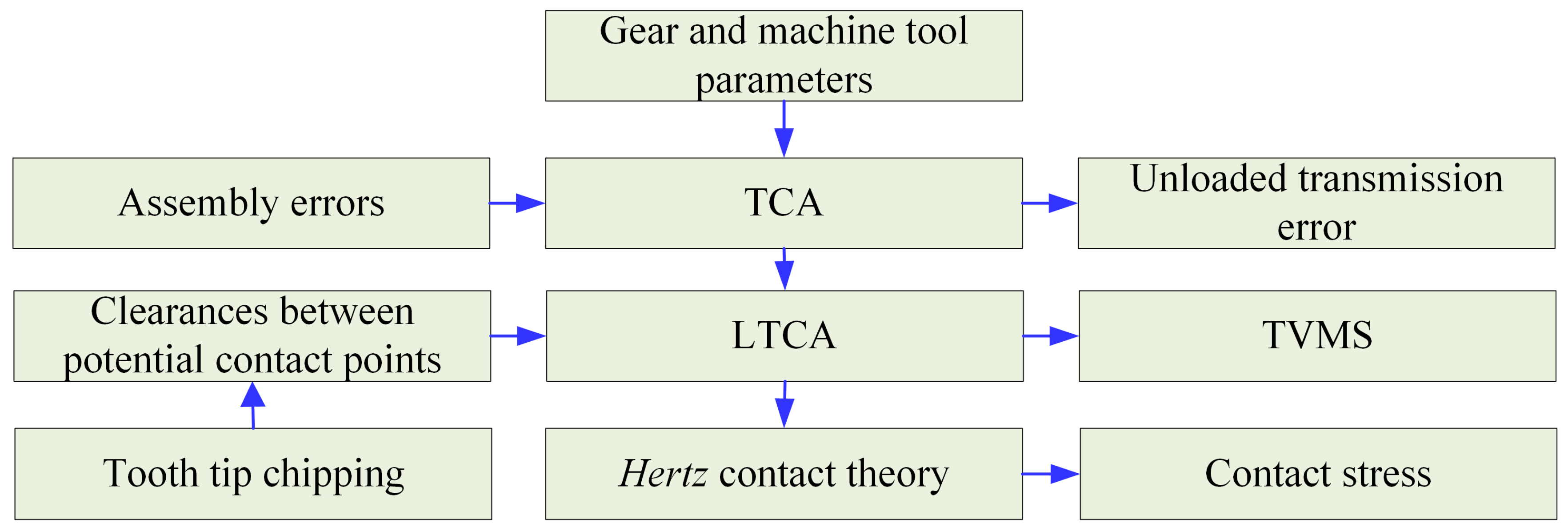
2. Loaded Tooth Contact Analysis of Spiral Bevel Gear Pairs

In this section, we will introduce an enhanced method which is a LTCA of SBGs considering assembly error and tooth tip chipping.

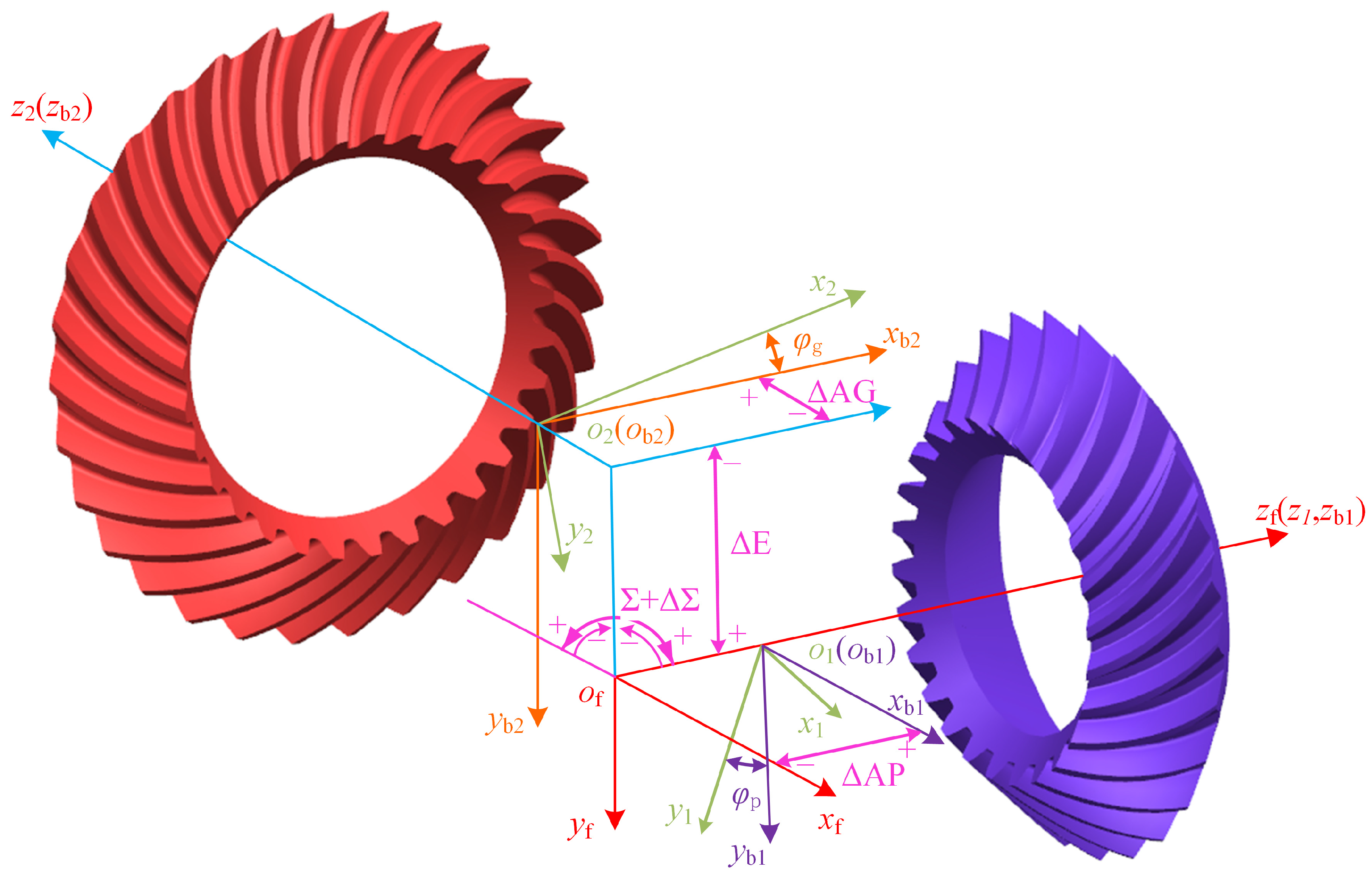
2.1. Loaded Tooth Contact Analysis Considering Assembly Error

The method proposed in this paper is based on loaded tooth contact analysis of spiral bevel gear pairs. The detailed processes of TCA and LTCA are stated in the paper published by Li et al. [31]. Here is a brief introduction to the key parts of TCA and LTCA:
The TCA is divided into two parts: (1) calculating discrete points of pinion and gear by accounting for both the engagement relationship between the tooth and cutter, which are in conjugate contact, and the projection relationship between three-dimensional space and the rotating projection plane; and (2) calculating the corresponding rotor angle and initial contact points when pinion and gear are meshing according to the conditions of continuous tangency between pinion and gear in the assembly coordinate system.
The LTCA can be generalized into four parts: (1) establishing a model and meshing grid according to the discrete points of pinion and gear; (2) determining the points along the long axis of the contact ellipse, which represents the intersection between the normal vector and the tooth surface, at all moments by translating the normal vector; (3) obtaining the global compliance matrix by traversal loading method and interpolation; and (4) calculating the distributed force and the rotation angle induced by the torque of pinion by solving the equation governing compatibility.
Assembly errors do not directly impact the tooth, therefore, here we will only introduce the method for bringing four assembly errors into TCA.
As shown in Figure 2, S1(x1, y1, z1) and S2(x2, y2, z2) are coordinate systems of pinion and gear, respectively; Sb1(xb1, yb1, zb1) and Sb2(xb2, yb2, zb2) are the auxiliary coordinate systems; and Sf(xf, yf, zf) is the meshing coordinate system. When transforming coordinate systems of pinion and gear into the meshing coordinate system, it can introduce assembly errors through the transfer matrix. This can be described as:
M f 1 = [ 1 0 0 0 0 1 0 0 0 0 1 Δ A P 0 0 0 1 ] [ cos Φ p sin Φ p 0 0 sin Φ p cos Φ p 0 0 0 0 1 0 0 0 0 1 ]
M f 2 = [ 1 0 0 0 0 1 0 Δ E 0 0 1 Δ AG 0 0 0 1 ] [ cos ( Σ + Δ Σ ) 0 sin ( Σ + Δ Σ ) 0 0 0 0 0 sin ( Σ + Δ Σ ) 0 cos ( Σ + Δ Σ ) 0 0 0 0 1 ] [ cos Φ g sin Φ g 0 0 sin Φ g cos Φ g 0 0 0 0 1 0 0 0 0 1 ]
where ΔAP is the axial assembly error of pinion; ΔAG is the axial assembly error of gear; ΔE is the offset error; ΔΣ is the shaft angle error; and Φp and Φg are the rotation angle of pinion and gear.
Then, the tooth surface equation and the normal vector of pinion and gear in the meshing coordinate system considering assembly errors can be calculated as:
{ r p ( f ) = M f 1 r 1 , n p ( f ) = L f 1 n 1 r g ( f ) = M f 2 r 2 , n g ( f ) = L f 2 n 2
where, r p ( f ) and r g ( f ) are the coordinates of pinion and gear in the meshing coordinate system, respectively; r1 and r2 are the coordinates of pinion coordinate system and gear coordinate system, respectively; n p ( f ) and n g ( f ) are the normal vector of tooth surface of pinion and gear in the meshing coordinate system, respectively; n1 and n2 are the normal vectors of pinion coordinate system and gear coordinate system, respectively; Lf1 is the first three order transformation matrix of matrix Mf1; and Lf2 is the first three order transformation matrix of matrix Mf2.
Given the rotor angle of the pinion (Φp), solving Equation (4) can obtain the rotor angle of the gear (Φg) and the coordinate of the initial contact point when unloaded. The contact trajectory is composed of the initial contact points
{ n 2 v ( g 2 ) = 0 r p ( f ) r g ( f ) = 0 n p ( f ) + n g ( f ) = 0
where v(g2) denotes the relative velocity of the virtual generating gear face and the machined gear face is represented in S2.
The unloaded transmission error can be calculated as follows:
s t e = Φ g z p z g Φ p
where zp and zg are the tooth numbers of the pinion and gear, respectively.
We did not consider lubrication in our analysis because the presented method was a quasi-static approach. According to LTCA, the TVMS can be calculated by iterating the equation of compatibility which takes normal forces of contact points and the angle of pinion as a solution. The equation governing compatibility at an arbitrarily chosen meshing moment is as follows:
[ ( λ c + λ b ) R n × 1 R 1 × n 0 ] [ F n × 1 θ lte ] = [ ε n × 1 T ]
where λb is the global compliance matrix (see in [31]); λc is the contact compliance matrix (see in [31]); Rn×1 and Rn are the distance from the initial contact point corresponding to the meshing moment of the rotating axis of pinion or gear; εn×1 is the clearance between the corresponding contact points at pinion and gear at the meshing moment; T is the input torque; θlte is the rotation angle induced by the load of the pinion at different meshing moments; and Fn×1 is the distributed normal force of potential contact points.
Following this, we can obtain the contact area (see Figure 3), which consists of potential contact points for which the distributed normal force exceeds zero for various meshing moments of SBG. Figure 3a is the rotating projection of a healthy pinion without assembly error and tooth tip chipping, and Figure 3b depicts the contact area on the rotating projection of the pinion considering the gear axial error ΔAG = 0.5 mm. Observations reveal that when the gear axial error ΔAG is 0.5 mm, the contact area shifts towards the tooth tip and heel.
As shown in Figure 4, a three-tooth model is established in MATLAB (R2021b) software. The proposed method needs only to get the global compliances obtained by the traversal loading method. Therefore, we constrain all degrees of nodes at the bottom surface of the pinion and gear when simulating the working conditions of SBG pairs. The elements used are 8-node hexahedral elements. Moreover, it is worth noting that the grids in the contact area are not fine, as satisfactory global compliances can be achieved through spatial interpolation and contact compliances can be estimated using empirical formulas instead of direct contact calculations.
TVMS of SBGs can be expressed as:
K t i m e = T ( R sin δ 1 cos α cos β θ l t e min ( ε 1 , ε 2 , ε i , ε n ) ) × R sin δ 1 cos α cos β θ l t e
where, R is the mean cone distance; the δ1, α, β are the pitch angle, pressure angle, and mean spiral angle, respectively.
Hertz contact theory plays a significant role in making out the local stress and strain between two subjects contacting due to pressure. This paper utilizes Hertz contact theory to calculate the contact stress of SBG pairs. To apply Hertz contact theory, it is essential to obtain the curvature of each potential contact point. There is a three-point method to obtain the curvature. According to three spatial points P1 (x1, y1, z1), P2 (x2, y2, z2), and P3 (x3, y3, z3) along the direction of the short axis of the contact ellipse at the mesh moment, which has tiny intervals and an intermediate point which is the potential contact point, an equation set can be listed as:
{ | x y z 1 x 1 y 1 z 1 1 x 2 y 2 z 2 1 x 3 y 3 z 3 1 | = 0 ( x 1 x ) 2 + ( y 1 y ) 2 + ( z 1 z ) 2 = 1 κ c ( x 2 x ) 2 + ( y 2 y ) 2 + ( z 2 z ) 2 = 1 κ c ( x 3 x ) 2 + ( y 3 y ) 2 + ( z 3 z ) 2 = 1 κ c
where the (x, y, z) is the coordinate of the center of the circle across the three points, and κc is the three-point curvature of the corresponding potential contact point.
When having the coordinate of the center of a circle, the curve normal vector n can be computed by the positional relationship between three points and the center point. The surface normal curvature κn is obtained by projecting the three-point curvature onto the tooth surface normal vector n(f) at the potential contact point [2], which can be expressed as:
κ n = κ c n n ( f )
According to Hertz contact theory, the contact stress at potential contact point can be given as:
σ H = F n ( κ n p + κ n g ) π L ( 1 μ 1 2 E 1 + 1 μ 2 2 E 2 )
where Fn is the distributed normal force at the potential contact point; L is the distance between the two adjacent potential contact points; κ n p and κ n g are the surface normal curvature at the potential contact point of pinion and gear, respectively; μ1 and μ2 are the Poisson ratio of pinion and gear; and E1 and E2 are the elasticity modulus of pinion and gear.

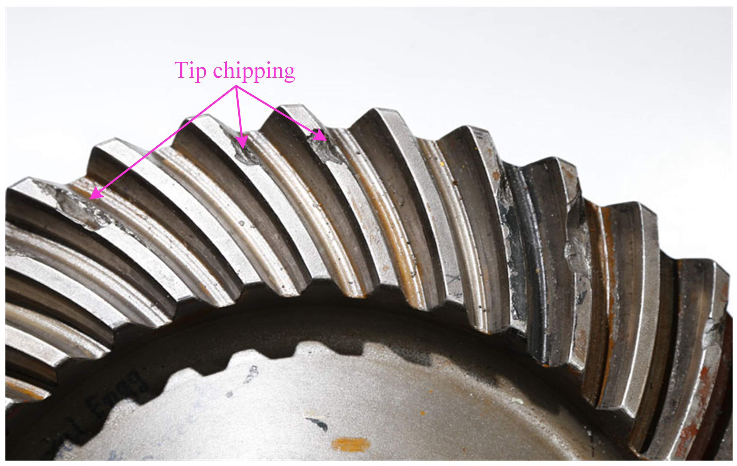
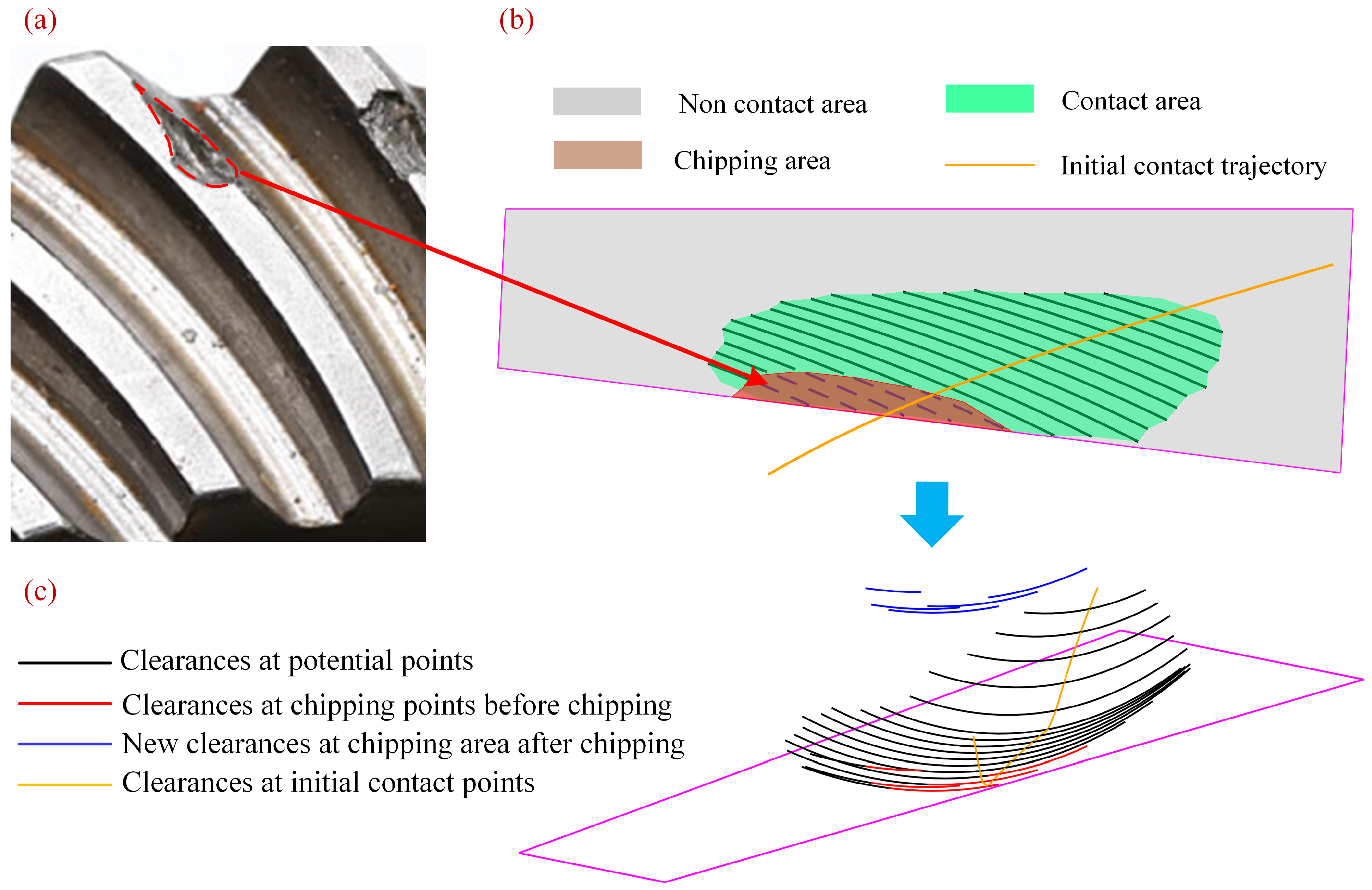
2.2. Loaded Tooth Contact Analysis Considering Assembly Error and Tooth Tip Chipping

In the absence of load, there is local point contact. The contact points can form a line known as the initial contact trajectory during a mesh cycle. To simplify calculations, this trajectory is represented by dispersed points which are called initial contact points. When under load, SBGs transition to elliptical contact. To simplify calculations, we utilize a line which is long enough but cannot exceed the tooth profile along the long axis of the elliptical contact region instead of elliptical contact surfaces. Additionally, the line is represented by dispersed points, referred to as potential contact points, for further simplification.
The proposed method can accurately incorporate and take into consideration the actual shapes of the tooth tip chipping. Initially, it needs to extract the shape (see Figure 5a) of tooth tip chipping from the gear affected by the chipping fault. When tooth tip chipping occurs, there is a reduction in the clearances between the pinion and gear within the chipping area (see Figure 5b). For simulating the occurrence of tooth tip chipping, this paper adjusts the clearances (see Figure 5c) between the potential contact points within the chipping area to represent the chip. The increased values in clearance reflect the depth of tooth tip chipping, whereas the extent of the chipped area is presented by the potential contact points for which clearances are altered. Subsequently, the equation governing compatibility is solved anew using the updated clearances, enabling the analysis of the mesh characteristics of the gear under tooth tip chipping fault.
The method presented in this paper is outlined in a simplified flowchart depicted in Figure 6. Firstly, based on the gear and machine tool parameters, the assembly errors are incorporated into the TCA to acquire the data for LTCA and to calculate the unloaded transmission error. Subsequently, LTCA is executed. Prior to assessing the compatibility, tooth tip chipping is indicated by noting the changes in clearance within the tooth tip chipping area. Following this, the TVMS can be computed using the compatibility equation. Finally, contact stress is determined using the Hertz contact formula, leveraging the curvature and normal force at potential contact points obtained from LTCA.

3. Model Verification and Discussion

This section will validate the LTCA considering assembly error with literature and analyze the effect of assembly error and tooth tip chipping for TVMS, transmission error, and contact stress of SBGs.

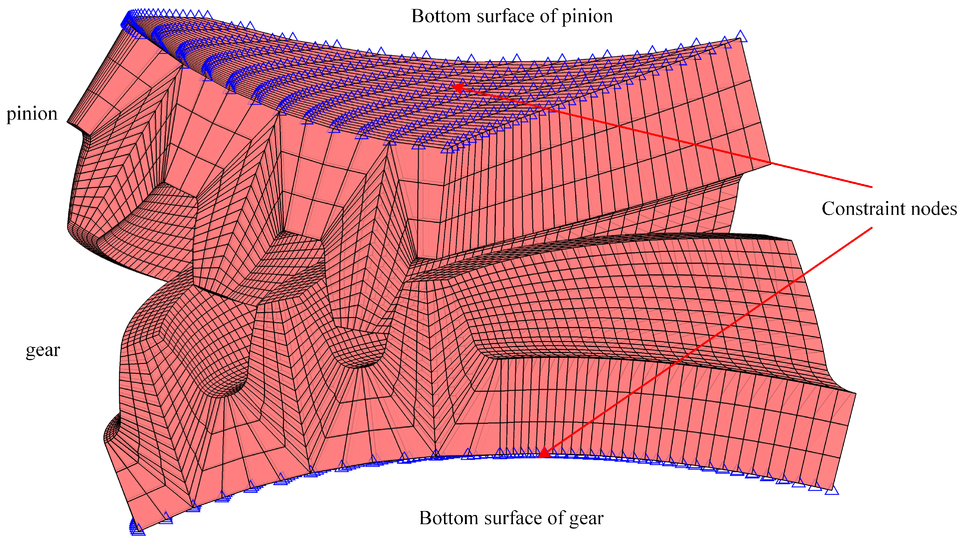
3.1. Model Verification of Spiral Bevel Gears Considering Assembly Error

For validating the correctness of the proposed method in this paper, geometry parameters and machining parameters of the example SBGs [31] which are shown in Table 1 and Table 2 are computed by the proposed method.
On the rotating projection of the gear tooth surface, the contact trajectories of the example SBGs obtained by the presented method under different assembly errors are compared in Figure 7. In addition, the comparisons of contact trajectories due to assembly errors in Han’s paper [16] are displayed in Figure 8. It is obvious that the variation trend of ΔAP, ΔAG, and ΔE is the same. The variation trend of ΔΣ is different because the direction of ΔΣ between this paper and Han’s work is opposite. Additionally, comparing the amounts of movement in the trajectories is challenging due to the differences in SBG pairs. The variation trend can also be verified by the publications of Pisula J [19] and Wang B [13]. It should be noted that the direction of ΔE in those two literatures is opposite to ours.

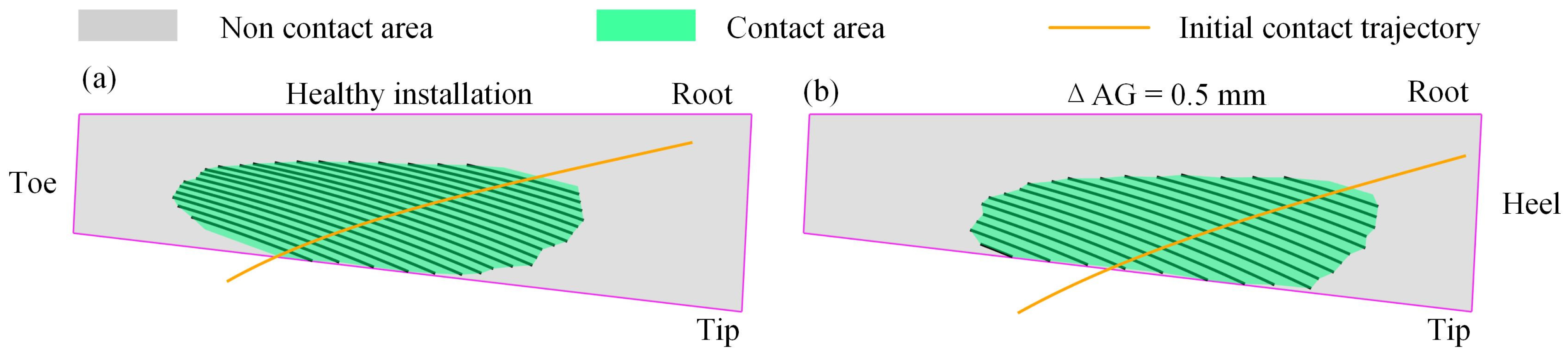
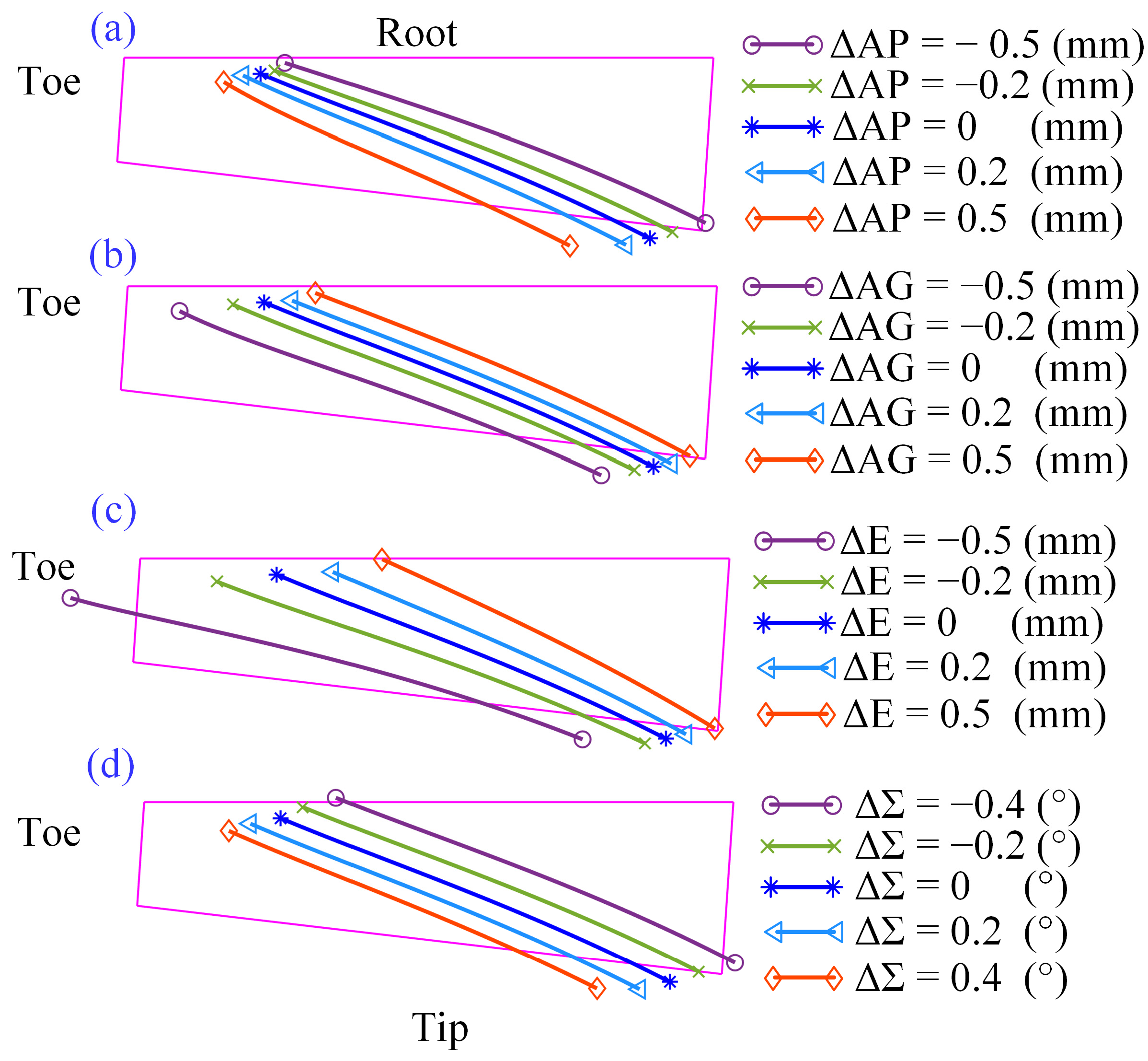
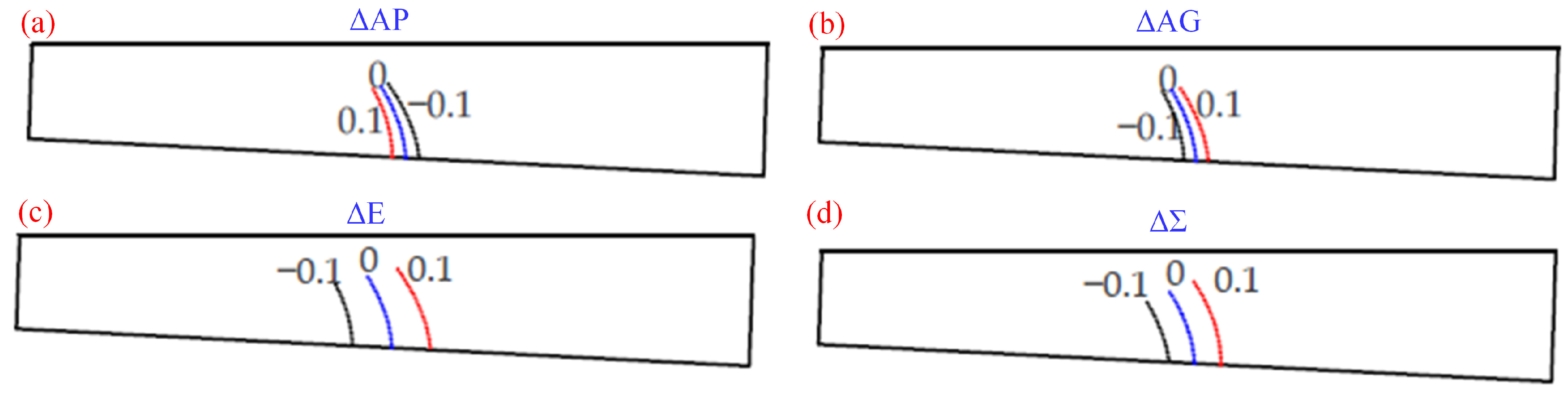
3.2. Effects of Assembly Error

The effects of assembly error are investigated in this section. There are three aspects to illustrate illustrating the effects of assembly error. They are the TVMS, unloaded transmission error, and contact stress. There are four values for ΔAP, ΔAG and ΔE, which are −0.5 mm, −0.2 mm, 0.2 mm, 0.5 mm, and four values for ΔΣ, which are −0.4°, −0.2°, 0.2°, 0.4°. Following this, the two chip areas are compared and the effects of tooth tip chipping discussed further.
The TVMS of SBGs considering four types of assembly errors are shown in Figure 9. From this, the following four main points can be concluded: (1) It is evident that the TVMS generally increases with the increment of ΔAP (see Figure 9a) with the exception of ΔAP = 0.5 mm. In addition, the amplitude of variation of negative value has a greater increases than that of positive value. (2) The TVMS considering ΔAG and ΔE decrease with the increase of ΔAG and ΔE with the exception of ΔAG = −0.5 mm and ΔE = −0.5 mm. Moreover, the amplitude of variation for ΔAG and ΔE is larger compared to that of ΔAP and ΔΣ. (3) Regarding ΔΣ, there is a small reduction in TVMS with the increase of the absolute value of ΔΣ. (4) Notably, when ΔAP = 0.5 mm, ΔAG = −0.5 mm, ΔE = −0.5 mm, and ΔΣ = −0.4°, the variations in TVMS deviate.
From the variations and trends above, it can be seen that all exhibit reductions in TVMS and peak-to-peak values of TVMS. This discrepancy arises from the contact of the tooth root, which can lead to extreme vibrations, loud noises, significant contact forces, and even crack formation, severely impacting the lifespan of SBGs. In practical applications, many SBGs undergo modifications to the tooth root to prevent contact. Consequently, the presented method solely considers the contact of the tooth surface. If there is contact in the tooth root area, the method will not distribute force to potential points in the tooth root area, resulting in a reduction in TVMS due to the decrease in bearing area.
The unloaded transmission errors considering different assembly errors are displayed in Figure 10. The range from the x-coordinate of the lowest point on the left side to zero is called the left meshing location and the range on the right side is called the right meshing location. There is a common phenomenon that the unloaded transmission errors will gradually equalize at the left meshing location and gradually reach their lowest point at the right meshing location. Due to the complexity of the SBG’s tooth surface, assembly errors will lead to changes in the contact area, resulting in unpredictable variations in unloaded transmission error. As of now, no specific rules can be summarized regarding these variations. Assembly errors can induce changes in unloaded transmission errors. Favorable changes, such as ΔAP = −0.5 mm and so forth, can increase the lowest point of unloaded transmission error.
The contact stresses of SBGs considering different assembly errors are shown in Figure 11. It is evident that the contact area, which consists of potential contact points wherein the contact stress exceeds zero, and the initial contact trajectory of ΔAP and ΔΣ move from heel and tip to toe and root. On the contrary, those of ΔAG and ΔE move from the toe and root to the heel and tip. In addition, with the movement of the contact area, the edge contact and the increase of tip stress appear gradually. This phenomenon alters the load distribution across the tooth surface and elevates the risk of tooth tip chipping. Moreover, it diminishes the service life of SBGs.

3.3. Effects of Tooth Tip Chipping

As Section 3.2 found, some assembly errors can result in edge contact and an increase in tip stress, ultimately leading to tooth tip chipping. Consequently, this section will discuss the effects of tooth tip chipping from three key aspects: TVMS, unloaded transmission error, and contact stress. Each assembly error selects a value characterized by edge contact and high tooth tip stress to introduce an identical area of chipping. They conclude ΔAP = −0.5 mm, ΔAG = 0.5 mm, ΔE = 0.5 mm, and ΔΣ = −0.4°.
In general, assembly errors will decrease TVMS in the influence range of tooth tip chipping (see Figure 12). A, B, D, E are the moments which have the maximal reduction of TVMS at ΔAP, ΔAG, ΔE and ΔΣ, respectively. The reduction of A (see Figure 12a), B (see Figure 12b), D (see Figure 12c), and E (see Figure 12d), is 3.28%, 3.92%, 4.91, 3.88%, respectively. It is evident that the effect of ΔE is the most significant when compared to ΔAP and ΔAG at the same error magnitude. ΔAP exhibits the smallest effect, although its influence range on tooth tip chipping is the widest. An intriguing observation is that the TVMS of ΔAP and ΔE may exhibit increases at certain points in time. For example, the TVMS of moment C (see Figure 12c) increased 2.31%. That is because tooth tip chipping causes a change in the smallest clearance (see Figure 13a). Due to tooth tip chipping, the clearances at the chipping region increase, and the smallest clearance changes from M (0 mm) in tooth 1 to P (0.0113 mm) in tooth 1. It is worth noting that the clearance at P is nearly equal to N located in tooth 2. Tooth 1 initially bears a load of 12.45 kN (see Figure 13b), whereas tooth 2 carries 14.76 kN before tooth tip chipping occurs. However, following tooth tip chipping, there is a shift in load distribution, with tooth 2 now bearing a heavier load of 18.48 kN, surpassing by far tooth 1’s load of 8.64 kN.
As shown in Figure 14, The unloaded transmission error experiences varying degrees of reduction as a result of tooth tip chipping. The reduction of ΔE = 0.5 mm (see in Figure 14c) is 131.3402 μrad which is the most significant and the reduction of ΔΣ = −0.4° (see in Figure 14d) is 62.1242 μrad which is the smallest relative to the other three assembly errors. The effect of ΔAP = −0.5 mm (see in Figure 14a) is similar to ΔAG = 0.5 mm (see in Figure 14b). The comparison of contact stress considering the four assembly errors under tooth tip chipping is displayed in Figure 15. When tooth tip chipping occurs, the area of the chip does not bear the load force, thereby increasing the contact stress near the edge of the chipping area. For instance, with ΔAG = 0.5 mm, the maximum contact stress reaches 1356.5 MPa. In contrast, the maximum contact stress for a healthy assembly is only 1186.9 MPa.
The effects of different sizes of chips may lead to different changes in mesh characteristics. Figure 16 showcases the TVMS for different chip areas under healthy installation and E = 0.5 mm. Figure 17 illustrates the unloaded transmission error and contact stress for different chip areas. There are two sizes of tooth tip chipping to compare and analyze, Chip_1 and Chip_2 (see Figure 17). Firstly, when the installation is healthy, the maximum reduction of Chip_1 is 0.91% and this appeared at moment K (see in Figure 16a), and the maximum reduction of Chip_2 is 3.56% and this appeared at moment J (see in Figure 16a) under healthy installation. Following this, when the installation is ΔE= 0.5 mm, the reductions at moments F, G, H, I are listed in Table 3 under ΔE = 0.5 mm. The max reduction of Chip_1 is 0.8% and this appeared at moment H (see in Figure 16b) and the max reduction of Chip_2 is 4.92% and this appeared at moment G (see in Figure 16b). It is simple to deduce that assembly errors increase the reduction of TVMS under tooth tip chipping. Why Chip_1 decreases the healthy installation is due to single tooth contact when Chip_1 happens.
As shown in Figure 17a, the larger the chip area, the greater the reduction in unloaded transmission errors. The OQ and RT are the moments of the affected regions by Chip_1 and Chip_2, respectively. For instance, the maximum reduction in unloaded transmission errors in Chip_1 is 48.3884 μrad, which is smaller than the 131.3402 μrad observed in Chip_2. The maximum contact stress of Chip_1 (see in Figure 17b) is 1204.7 MPa and Chip_2 (see in Figure 17b) is 1324.7 MPa. Additionally, it is apparent that the contact moment affected by Chip_1 (OQ) is less than that of Chip_2 (RT).

4. Conclusions

In this study, an enhanced method is proposed for analyzing the mesh characteristics of spiral bevel gears (SBGs), taking into account assembly errors and tooth tip chipping. This method is primarily based on tooth contact analysis (TCA) and loaded tooth contact analysis (LTCA) and has been validated using existing literature. The study explores the effects of assembly errors and tooth tip chipping and the conclusions can be summarized as follows:
(1)
The enhanced method has been validated through the consistency of variation trends observed between this paper and previously published literature, considering different assembly errors.
(2)
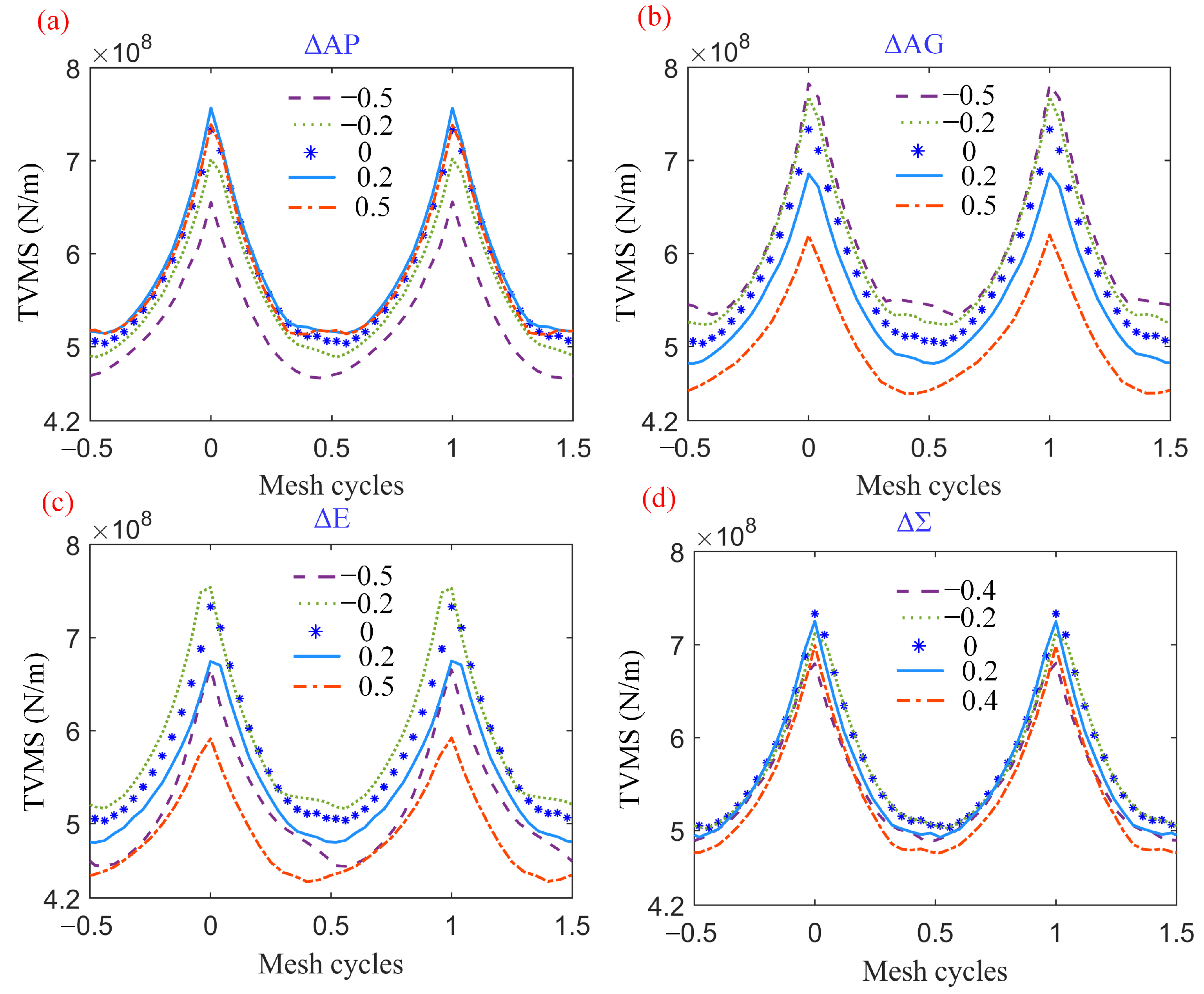
When the contact area moves to the tip, the peak-to-peak value of time-varying meshing stiffness (TVMS) will reduce. In addition, the TVMS has different kinds of increases or decreases with the increase of assembly errors.
(3)
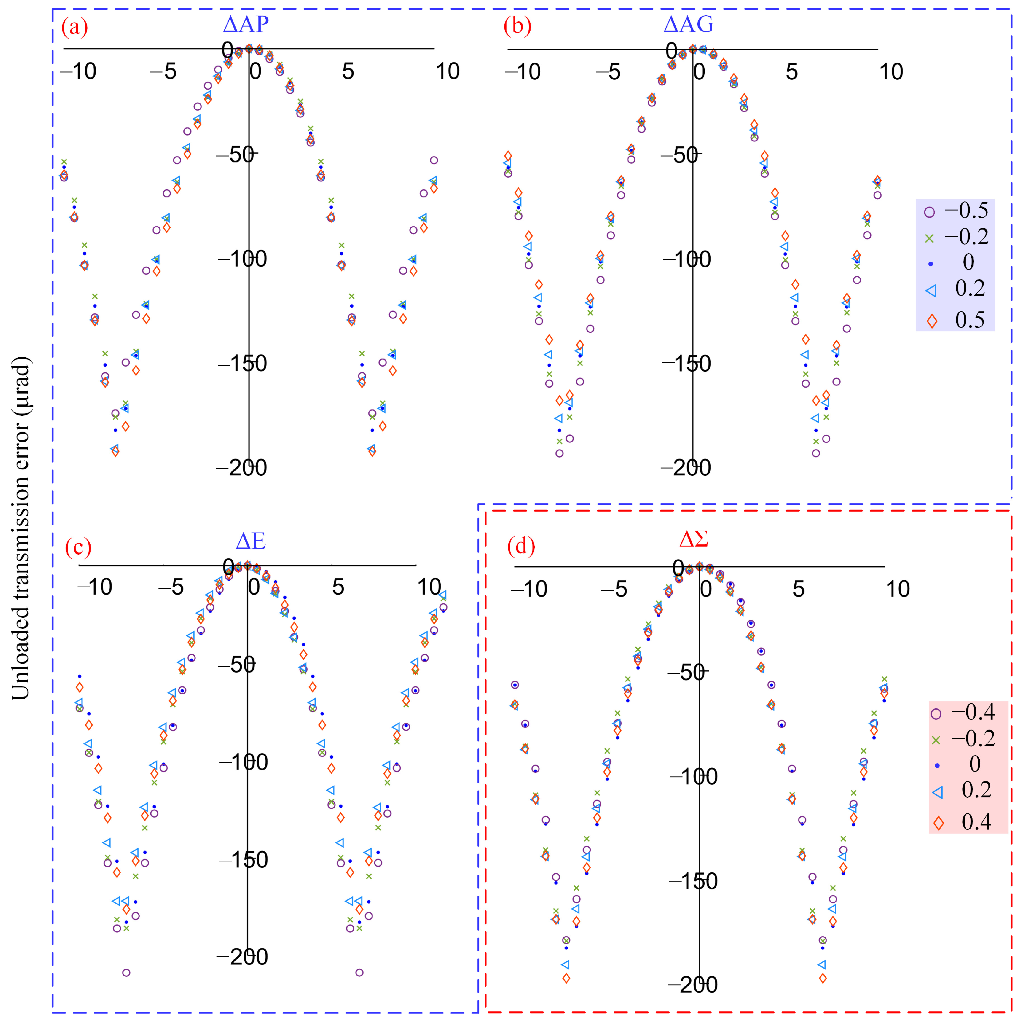
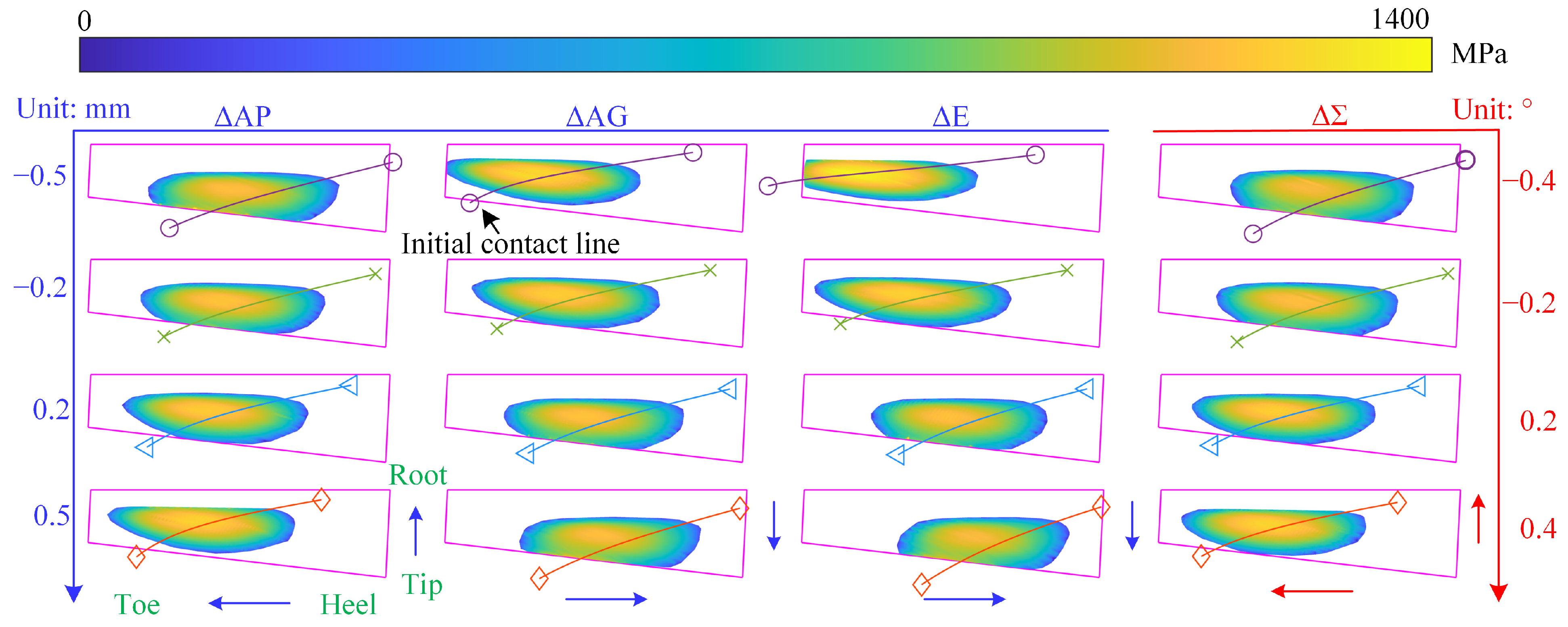
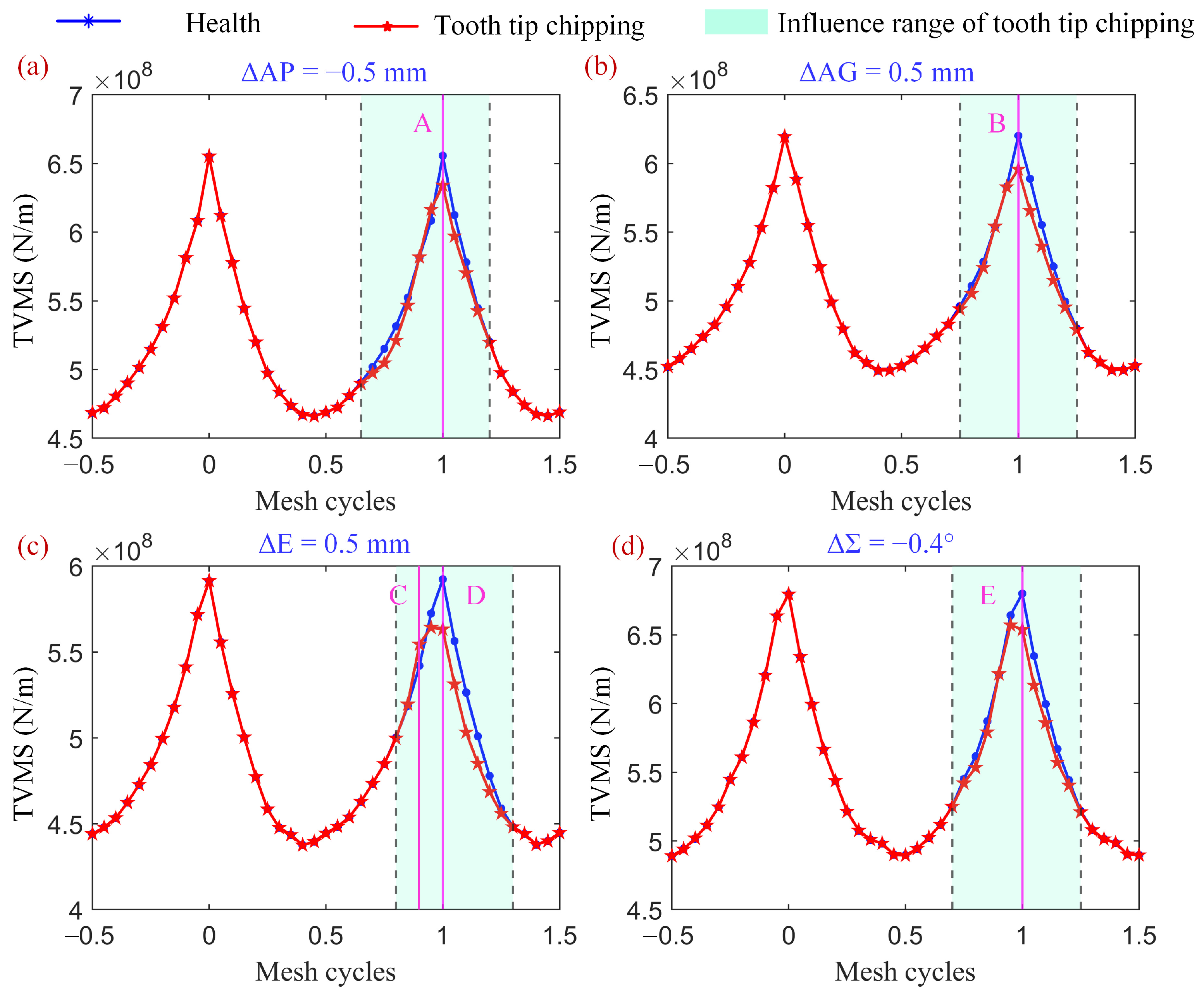
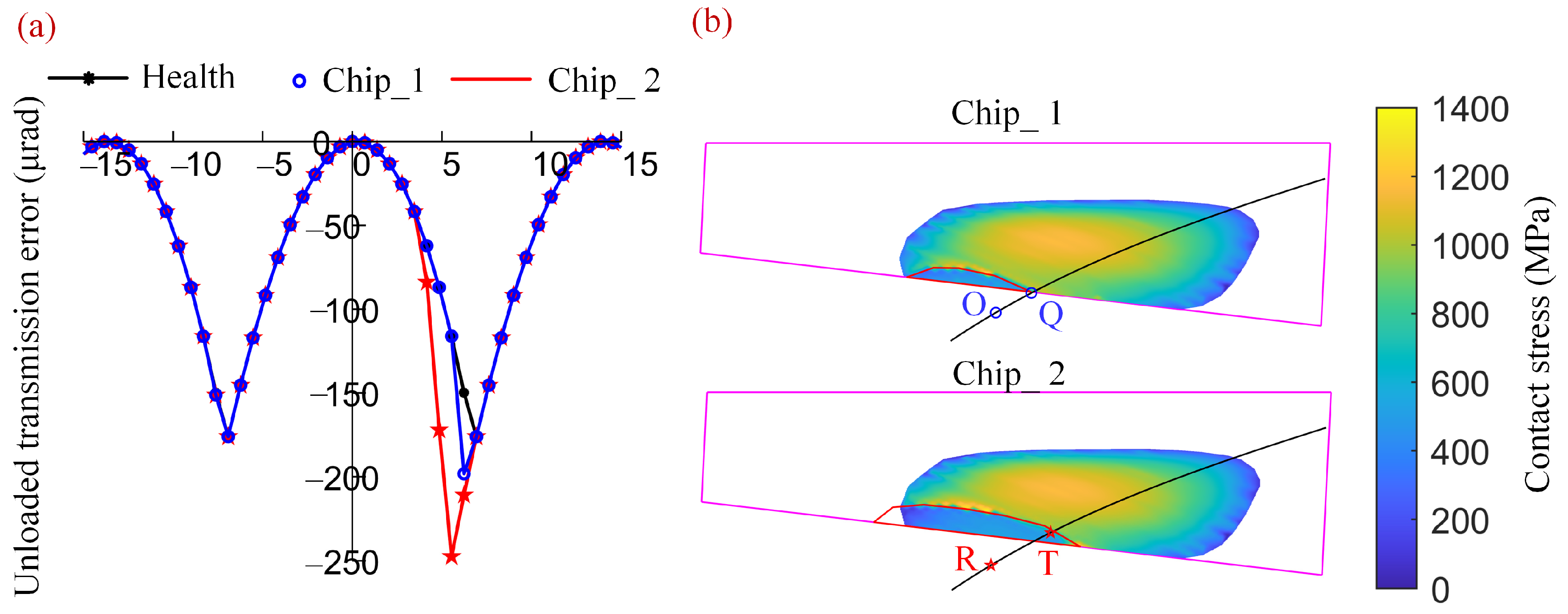
Assembly errors lead to an escalation in contact stress at the tooth tip, amplifying the risk of tooth tip chipping. Tooth tip chipping decreases the TVMS and unloaded transmission error within the affected region, whilst concurrently increasing the maximum contact stress. Furthermore, for identical chips, the TVMS considering assembly errors exhibits a more pronounced decline compared to a healthy installation.

Author Contributions

Conceptualization, Z.L. and R.L.; Software, J.Z.; Formal analysis, Y.W.; Investigation, J.Z.; Resources, Z.L.; Project administration, Y.W.; Funding acquisition, Z.L., R.Z. and H.M. All authors have read and agreed to the published version of the manuscript.

Funding

This work is supported by the National Natural Science Foundation of China (Grant No. 52205108), Key Laboratory of Vibration and Control of Aero-Propulsion System, Ministry of Education, Northeastern University (Grant No. VCAME202201), Natural Science Foundation of Jiangsu Province of China (Grant No. BK20220897), National defense technology basic research project of China (JSZL2022110A074) and Postdoctoral research merit-based funding project of Zhejiang Province (ZJ2022129).

Data Availability Statement

The data that support the findings of this study are available from the corresponding author upon reasonable request.

Conflicts of Interest

Author Ying Wang was employed by the company AECC Harbin Dongan Engine Co., Ltd. The remaining authors declare that the research was conducted in the absence of any commercial or financial relationships that could be construed as a potential conflict of interest.

Nomenclature

E1 and E2Modulus of elasticity of pinion and gear, respectively
FnDistributed normal force at potential contact point
Fn×1Distributed normal force of potential contact points
LDistance between the two adjacent potential contact points
Lf1 and Lf2First three-order transformation matrix of matrix Mf1 and Mf2, respectively
Mf1 and Mf2Coordinate transformation matrix from S1 and S2 to Sf
n1 and n2Normal vector of one point at pinion and gear coordinate system, respectively
n p ( f ) and n g ( f ) Normal vector of the unloaded contact point on the pinion and gear tooth face, respectively
nThree-point curve normal vector
n(f)Tooth surface normal vector of potential contact point at meshing coordinate system
r1 and r2Coordinates of the unloaded contact point at pinion and gear coordinate system, respectively
r p ( f ) and r g ( f ) Coordinates of the unloaded contact point on the pinion and gear tooth face, respectively
RMean cone distance
steStatic transmission error
Sb1 and Sb2Auxiliary coordinate system of pinion and gear, respectively
S1 and S2Pinion and gear coordinate system, respectively
TInput torque
v(g2)Relative velocity of the virtual generating gear face and machined gear face represented in S2
zp and zgTooth numbers of the pinion and gear, respectively
Greek symbols
ΔAPAxial assembly error of pinion
ΔAGAxial assembly error of gear
ΔEOffset error
ΔΣShaft angle error
ΣShaft angle
Φp and ΦgRotor angle of the pinion and gear, respectively
αPressure angle
βMean spiral angle
δ1Pitch angle of the spiral bevel gear
εiClearance of the ith corresponding potential point
εn×1Clearance between corresponding contact points at pinion and gear at meshing moments
θlteRotation angles of driving pinion at different meshing moments
κc and κnThree-point curvature and surface normal curvature, respectively
κ n p and κ n g Surface normal curvature at potential contact point of pinion and gear, respectively
λbGlobal compliance matrix
λcContact compliance matrix
μ1 and μ2Poisson ratio of pinion and gear, respectively
Abbreviations
ETCAError Tooth Contact Analysis
FEAFinite Element Analysis
FEMFinite Element Method
LTCALoaded Tooth Contact Analysis
SBGSpiral bevel gear
TCATooth contact analysis
TVMSTime-varying meshing stiffness

References

  1. Ding, H.; Tang, J.; Shao, W.; Peng, S. An innovative determination approach to tooth compliance for spiral bevel and hypoid gears by using double-curved shell model and Rayleigh–Ritz approach. Mech. Mach. Theory 2018, 130, 27–46. [Google Scholar] [CrossRef]
  2. Vivet, M.; Mundo, D.; Tamarozzi, T.; Desmet, W. An analytical model for accurate and numerically efficient tooth contact analysis under load, applied to face-milled spiral bevel gears. Mech. Mach. Theory 2018, 130, 137–156. [Google Scholar] [CrossRef]
  3. Chen, S.; Zhang, A.; Wei, J.; Lim, T.C. Nonlinear excitation and mesh characteristics model for spiral bevel gears. Int. J. Mech. Sci. 2023, 257, 108541. [Google Scholar] [CrossRef]
  4. Litvin, F.L.; Fuentes, A. Gear Geometry and Applied Theory; Cambridge University Press: Cambridge, UK, 2004. [Google Scholar]
  5. Li, H.; Tang, J.; Chen, S.; Ding, H.; Sun, Z.; Rong, K. Analytical calculation of mesh stiffness for spiral bevel gears with an improved global tooth deformation model. Mech. Mach. Theory 2024, 191, 105492. [Google Scholar] [CrossRef]
  6. Fan, Q.; Wilcox, L. New Developments in Tooth Contact Analysis (TCA) and Loaded TCA for Spiral Bevel and Hypoid Gear Drives; AGMA: Madison, WI, USA, 2005. [Google Scholar]
  7. Guo, C.H.; Yang, W.T.; Liu, Z.; Zhang, Z.M. Tooth contact analysis and transmission error optimization for Klingelnberg spiral bevel gear. Appl. Mech. Mater. 2013, 310, 323–327. [Google Scholar] [CrossRef]
  8. Krenzer, T.J. Tooth contact analysis of spiral bevel and hypoid gears under load. SAE Trans. 1981, 90, 2205–2216. [Google Scholar]
  9. Hou, X.; Fang, Z.; Fu, X.; Zhang, X. Meshing performance of spiral bevel gear with different loads and modules considering edge contact by finite element method. Trans. Can. Soc. Mech. Eng. 2019, 43, 322–332. [Google Scholar] [CrossRef]
  10. Bingyang, W.; Xiaozhong, D.; Angxin, T. Surface synthesis method on generating parameters computation of spiral bevel-gears. J. Mech. Eng. 2016, 52, 20–25. [Google Scholar]
  11. Bingyang, W.; Jianjun, Y.; Angxin, T. Tooth meshing simulation and analysis based on isometric mapping ease-off surface. J. Aerosp. Power 2017, 32, 1259–1265. [Google Scholar]
  12. Wei, B.-Y.; Li, J.-Q.; Cao, X.-M.; Han, C.-Y. Calculation of gear mesh stiffness and loaded tooth contact analysis based on ease-off surface topology. Adv. Mech. Eng. 2022, 14. [Google Scholar] [CrossRef]
  13. Wang, B.; Hua, L. Computerized Design and FE Simulation of Meshing of Involute Spiral Bevel Gears with Alignment Errors. Adv. Mater. Res. 2011, 199–200, 386–391. [Google Scholar] [CrossRef]
  14. Nishino, T. Computerized Modeling and Loaded Tooth Contact Analysis of Hypoid Gears Manufactured by Face Hobbing Process. J. Adv. Mech. Des. Syst. Manuf. 2009, 3, 224–235. [Google Scholar] [CrossRef]
  15. Liu, G.L.; Zhang, R.T.; Zhao, N. Quantitative Analysis of the Influence of Installation Errors on the Contact Pattern of Spiral Bevel Gears. Appl. Mech. Mater. 2011, 86, 278–282. [Google Scholar] [CrossRef]
  16. Han, H.; Ma, H.; Wang, H.; Zhu, J.; Li, Z.; Liu, Z. Dynamic Simulation of Cracked Spiral Bevel Gear Pair Considering Assembly Errors. Machines 2022, 10, 929. [Google Scholar] [CrossRef]
  17. Ding, H.; Zhou, Y.; Tang, J.; Zhong, J.; Zhou, Z.; Wan, G. A novel operation approach to determine initial contact point for tooth contact analysis with errors of spiral bevel and hypoid gears. Mech. Mach. Theory 2017, 109, 155–170. [Google Scholar] [CrossRef]
  18. Pisula, J. A mathematical model for designing tooth surfaces in spiral bevel gears and gear meshing analysis. Diagnostyka 2015, 16, 57–62. [Google Scholar]
  19. Pisula, J. An analysis of the effect of the application of helical motion and assembly errors on the meshing of a spiral bevel gear using duplex helical method. Adv. Manuf. Sci. Technol. 2016, 40, 19–31. [Google Scholar]
  20. Simon, V. Influence of tooth errors and misalignments on tooth contact in spiral bevel gears. Mech. Mach. Theory 2008, 43, 1253–1267. [Google Scholar] [CrossRef]
  21. Simon, V.V. Loaded tooth contact analysis and stresses in spiral bevel gears. In Proceedings of the International Design Engineering Technical Conferences and Computers and Information in Engineering Conference, San Diego, CA, USA, 30 August–2 September 2009; pp. 271–279. [Google Scholar]
  22. Jia, S.; Howard, I. Comparison of localised spalling and crack damage from dynamic modelling of spur gear vibrations. Mech. Syst. Signal Process 2006, 20, 332–349. [Google Scholar] [CrossRef]
  23. Wilk, A.B.; Madej, H.M.; Łazarz, B.E. Vibration Processing Techniques for Fault Detection in Gearboxes. In Proceedings of the International Design Engineering Technical Conferences and Computers and Information in Engineering Conference, Chicago, IL, USA, 2–6 September 2003; pp. 657–664. [Google Scholar]
  24. Tian, X. Dynamic Simulation for System Response of Gearbox Including Localized Gear Faults. Master’s Thesis, University of Alberta, Edmonton, AB, Canada, 2004. [Google Scholar]
  25. Wojnar, G.; Łazarz, B.; Madej, H. Diagnostics of power transmissions system with tooth gear. Transp. Probl. 2008, 3, 29–34. [Google Scholar]
  26. Yang, Y.; Hu, N.; Tang, J.; Hu, J.; Zhang, L.; Cheng, Z. Dynamic analysis for a spur geared rotor system with tooth tip chipping based on an improved time-varying mesh stiffness model. Mech. Mach. Theory 2021, 165, 104435. [Google Scholar] [CrossRef]
  27. Li, G.; Liang, X.; Li, F. Model-based analysis and fault diagnosis of a compound planetary gear set with damaged sun gear. J. Mech. Sci. Technol. 2018, 32, 3081–3096. [Google Scholar] [CrossRef]
  28. Han, J.; Liu, Y.; Liang, L.; Zhao, Y.; Zhang, H.; Bu, S. Dynamic Analysis of a Fault Planetary Gear System under Nonlinear Parameter Excitation. Shock. Vib. 2021, 2021, 1787525. [Google Scholar] [CrossRef]
  29. Liu, Y.; Shi, Z.; Shen, G.; Zhen, D.; Wang, F.; Gu, F. Evaluation model of mesh stiffness for spur gear with tooth tip chipping fault. Mech. Mach. Theory 2021, 158, 104238. [Google Scholar] [CrossRef]
  30. Han, H.; Yuan, K.; Ma, H.; Peng, Z.; Li, Z.; Zhao, S.; Wen, B. Mesh characteristic analysis and dynamic simulation of spur gear pair considering corner contact and tooth broken fault. Eng. Fail. Anal. 2023, 143, 106883. [Google Scholar] [CrossRef]
  31. Li, Z.; Zhang, J.; Song, H.; Zhu, R.; Ma, H. Time-varying mesh stiffness calculation of spiral bevel gear with spalling defect. Mech. Mach. Theory 2024, 193, 105571. [Google Scholar] [CrossRef]
  32. Dadon, I.; Koren, N.; Klein, R.; Bortman, J. A Step Toward Fault Type and Severity Characterization in Spur Gears. J. Mech. Des. 2019, 141, 083301. [Google Scholar] [CrossRef]
  33. Halim, E.B.; Shoukat Choudhury, M.A.A.; Shah, S.L.; Zuo, M.J. Time domain averaging across all scales: A novel method for detection of gearbox faults. Mech. Syst. Signal Process 2008, 22, 261–278. [Google Scholar] [CrossRef]
Figure 1. Tooth tip chipping of spiral bevel gear.
Applsci 14 03227 g001
Figure 2. Coordinate systems of SBG with assembly errors.
Applsci 14 03227 g002
Figure 3. Contact area of (a) healthy installation and (b) ΔAG = 0.5 mm.
Applsci 14 03227 g003
Figure 4. A three-tooth FEM model of SBG.
Applsci 14 03227 g004
Figure 5. Contact area and chipping area on the rotating projection of the pinion tooth surface, the actual shape of tooth tip chipping and the clearances change: (a) actual chip; (b) contain chipping and ΔAG = 0.5 mm (c) clearances change due to the chipping.
Applsci 14 03227 g005
Figure 6. Flow chart of LTCA considering assembly error and tooth tip chipping.
Applsci 14 03227 g006
Figure 7. Contact trajectories of different assembly errors on the rotating projection of the gear tooth surface: (a) ΔAP; (b) ΔAG; (c) ΔE; (d) ΔΣ.
Applsci 14 03227 g007
Figure 8. Comparison of contact trajectories due to the assembly errors in Han’s paper [16]: (a) ΔAP; (b) ΔAG; (c) ΔE; (d) ΔΣ.
Applsci 14 03227 g008
Figure 9. TVMS of SBG considering the different assembly errors: (a) ΔAP; (b) ΔAG; (c) ΔE; (d) ΔΣ.
Applsci 14 03227 g009
Figure 10. Unloaded transmission error of SBGs considering different assembly errors: (a) ΔAP; (b) ΔAG; (c) ΔE; (d) ΔΣ.
Applsci 14 03227 g010
Figure 11. Contact stress of SBGs considering different assembly errors.
Applsci 14 03227 g011
Figure 12. TVMS of different assembly errors considering tooth tip chipping: (a) ΔAP = −0.5 mm; (b) ΔAG = 0.5 mm; (c) ΔE = 0.5 mm; (d) ΔΣ = −0.4°.
Applsci 14 03227 g012
Figure 13. The clearances and distributed force between potential contact points at moment C: (a) the clearances; (b) the distributed force.
Applsci 14 03227 g013
Figure 14. Unloaded transmission error of different assembly errors considering tooth tip chipping: (a) ΔAP = −0.5 mm; (b) ΔAG = 0.5 mm; (c) ΔE = 0.5 mm; (d) ΔΣ = −0.4°.
Applsci 14 03227 g014
Figure 15. Contact stress of different assembly errors considering tooth tip chipping: (a) ΔAP = −0.5 mm; (b) ΔAG = 0.5 mm; (c) ΔE = 0.5 mm; (d) ΔΣ = −0.4°.
Applsci 14 03227 g015
Figure 16. TVMS of different chip areas under healthy installation and E = 0.5 mm: (a) healthy installation; (b) E = 0.5 mm.
Applsci 14 03227 g016
Figure 17. Unloaded transmission errors and contact stress of different chip areas under E = 0.5 mm: (a) unloaded transmission errors; (b) contact stress.
Applsci 14 03227 g017
Table 1. Basic geometry parameters of the example gear pair.
ParametersPinionGear
Tooth number2631
Module (mm)8.654
Shaft angle (°)90
Mean spiral angle (°)35
Face width (mm)57
Mean cone distance (mm)146.57
Hand of spiralLeftRight
Pitch angles (°)39.9850.01
Root angles (°)37.1346.17
Face angles (°)43.8352.87
Addendum (mm)8.276.44
Dedendum (mm)8.4710.31
Table 2. Machining parameters of the example gear pair.
ParameterPinionGear
ConcaveConvexConcaveConvex
Cutter point radius (mm)108.58112.05116.45112.15
Pressure angle (°)−17.5022.50−18.5021.50
Root fillet radius (mm)1.101.102.502.50
Machine center to back (mm)−4.346.9000
Sliding base (mm)2.14−4.681.461.46
Blank offset (mm)−2.502.500
Radial distance (mm)116.73127.5123.81123.81
Machine root angle (°)37.3837.3846.1746.17
Cradle angle (°)−51.07−53.0049.1349.13
Velocity ratio1.501.621.301.30
Modified Roll Coefficient C0.0197−0.023100
Modified Roll Coefficient D−0.01720.047700
Table 3. Reduction of TVMS of two chip areas at different moments under E = 0.5 mm.
Moment F
(%)
Moment G
(%)
Moment H
(%)
Moment I
(%)
Chip_10−0.43%−0.8%−0.24%
Chip_22.31%−4.92%−4.39%−1.94%
Disclaimer/Publisher’s Note: The statements, opinions and data contained in all publications are solely those of the individual author(s) and contributor(s) and not of MDPI and/or the editor(s). MDPI and/or the editor(s) disclaim responsibility for any injury to people or property resulting from any ideas, methods, instructions or products referred to in the content.

