Article

Enhancing Low-Voltage Distribution Network Safety through Advanced Residual Current Protection Techniques

1
School of Electrical Engineering, Shandong University, Jinan 250061, China
2
State Grid Shandong Electric Power Company, Jinan 250001, China
*
Author to whom correspondence should be addressed.
Appl. Sci. 2024, 14(8), 3256; https://doi.org/10.3390/app14083256
Submission received: 2 February 2024 / Revised: 5 April 2024 / Accepted: 9 April 2024 / Published: 12 April 2024

Abstract

:
Residual current protection can detect and isolate the grounding (leakage) fault of low-voltage distribution networks in time, which is an essential technical measure to reduce electric shocks and fire accidents and improve power supply safety. This paper systematically analyzes the operating characteristics of low-voltage distribution networks and proposes a distributed residual current protection method based on closed sections. It utilizes the capabilities of a distribution IoT platform to provide comprehensive measurement information for the entire substation area. A method was introduced to divide the low-voltage distribution substation into different protection closed surfaces, defining the current phasor at the external contact point of the closed surface and the remaining current of the closed surface. A calculation method for the critical current based on the remaining current of the closed surface for fault detection was proposed. Case studies have shown that this method is less affected by the inherent current and can significantly improve the sensitivity of protection. For TN-C and TN-C-S systems, in the selection of closed surfaces, the repeated grounding point of the neutral line is excluded from the closed surface. This method can also overcome the impact of residual current changes when load switching, demonstrating the flexibility of the new principle.

1. Introduction

Residual current protection plays a crucial role in earth (leakage) fault detection and protection technology within low-voltage distribution networks [1,2]. However, it is susceptible to influences from line distribution capacitance current and load fluctuation factors [3,4]. The detection of faults by residual current protection primarily relies on analyzing the power frequency amplitude, phase angle, and phasor changes of the residual current at the measurement point. The amplitude comparison method criterion is limited by the presence of inherent residual current during normal operation, leading to a protection dead zone [5,6].
The current pulse method relies on detecting sudden changes in the residual current amplitude for fault assessment. However, due to the unpredictable nature of fault current phase angles, a considerable protection dead zone exists. On the other hand, the phase and amplitude detection method assesses faults based on changes in the residual current amplitude and phase angle. Although effective in theory, the complexity of calculations often leads to protection migration and rejection issues in practical applications, resulting in less-than-ideal protection outcomes [7]. In contrast, the current separation method focuses on transient and steady-state characteristics of electric shocks. By isolating the electric shock current from the residual current and making judgments based on the electric shock current, this method successfully eliminates the protection dead zone. Current separation stands out as a primary research approach for electric shock protection [8,9,10,11]. During leakage faults in electrical equipment, the residual current exhibits non-sinusoidal characteristics, impacting the performance of Residual Current Devices (RCDs) [12,13]. Additionally, the increasing use of diverse power electronic equipment complicates the harmonic features of the inherent residual current, posing challenges for traditional leakage protection methods that rely on amplitude, phase angle, or time–frequency characteristics of residual current [14]. Significant magnitudes of residual current can render general and intermediate protection mechanisms inoperative, particularly in TN configurations with repeated grounding, highlighting the need for innovative solutions in electrocution protection research [15,16].
The inherent residual current in the low-voltage distribution network primarily originates from concentrated loads at the line’s ends and branches. The earthing point in TN configurations is typically situated at the user-side measuring box or electrical equipment, with the loop that amplifies residual current also located at the terminal load. Consequently, the actual inherent residual current in front of the user-side measuring box is minimal, allowing for the logical division of the protection range into distinct closed sections. The inherent residual current in these sections is significantly lower than that measured by general and intermediate protection devices installed on equipment, presenting an opportunity to enhance protection sensitivity. However, a challenge arises in selecting the closed sections. The need to isolate repeated earthing points of TN configurations outside these sections poses a significant challenge. This isolation is crucial for overcoming the limitation of installing residual current protection in TN configurations, thereby enhancing the safety of such configurations. Addressing this challenge is essential for improving the overall safety and effectiveness of protection measures in low-voltage distribution networks.
Through an in-depth examination of the residual current generation mechanism in low-voltage distribution networks, this study introduces a novel distributed residual current protection approach based on the closed-section method. This research delves into the impact of inherent residual current and the presence of repeated earthing in TN configurations on residual current protection functionality. An adaptive reach strategy for closed sections is proposed to enhance the effectiveness of the protection system. The findings demonstrate that the distributed residual current protection method, utilizing the closed-section approach, effectively addresses the challenge of detecting and isolating earth faults reliably. Promising results from demonstration projects underscore the method’s potential to significantly contribute to mitigating public safety concerns related to electric shock and electrical fires.

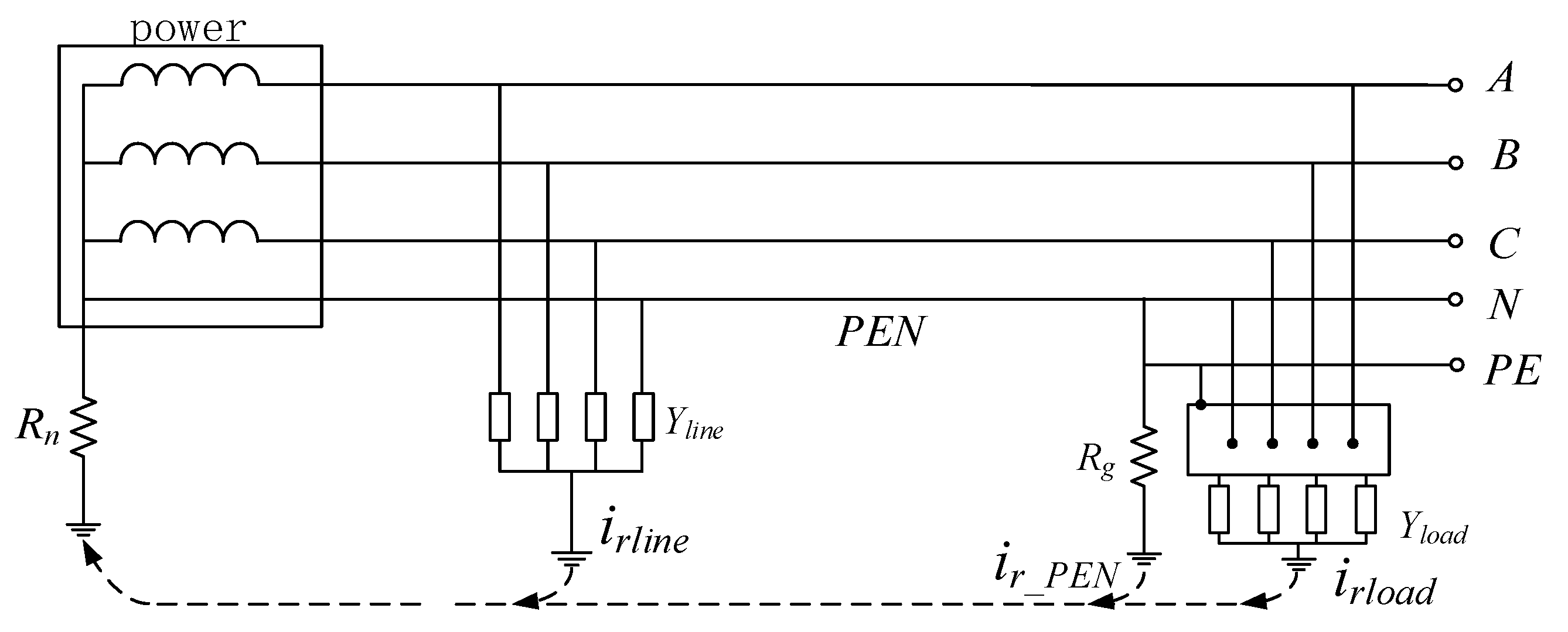
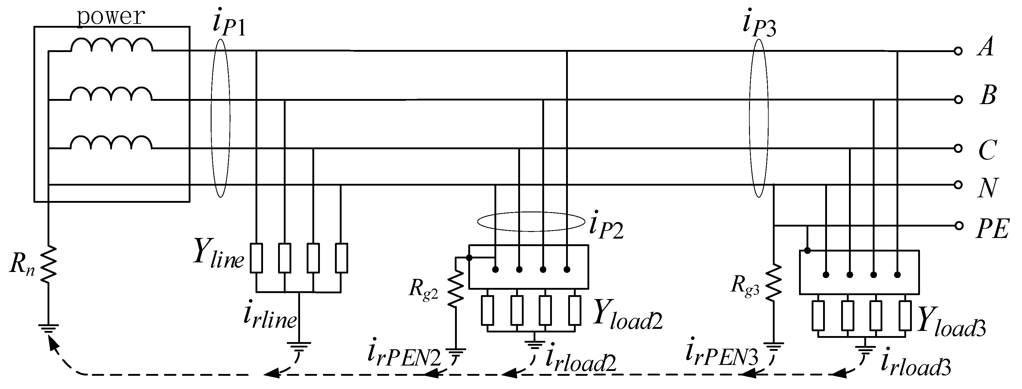
2. Analysis of Inherent Residual Current of Low-Voltage Distribution Networks

Residual current protection in low-voltage distribution networks is typically structured into three tiers: general protection, intermediate protection, and household protection, designed to facilitate time differential protection with selective disconnection capabilities. However, the effectiveness of current residual protection technologies falls short of expectations, leading to challenges in implementing TN-C and TN-C-S configurations. This limitation is primarily attributed to the substantial magnitude of the residual current (referred to as inherent residual current) present during normal network operations.

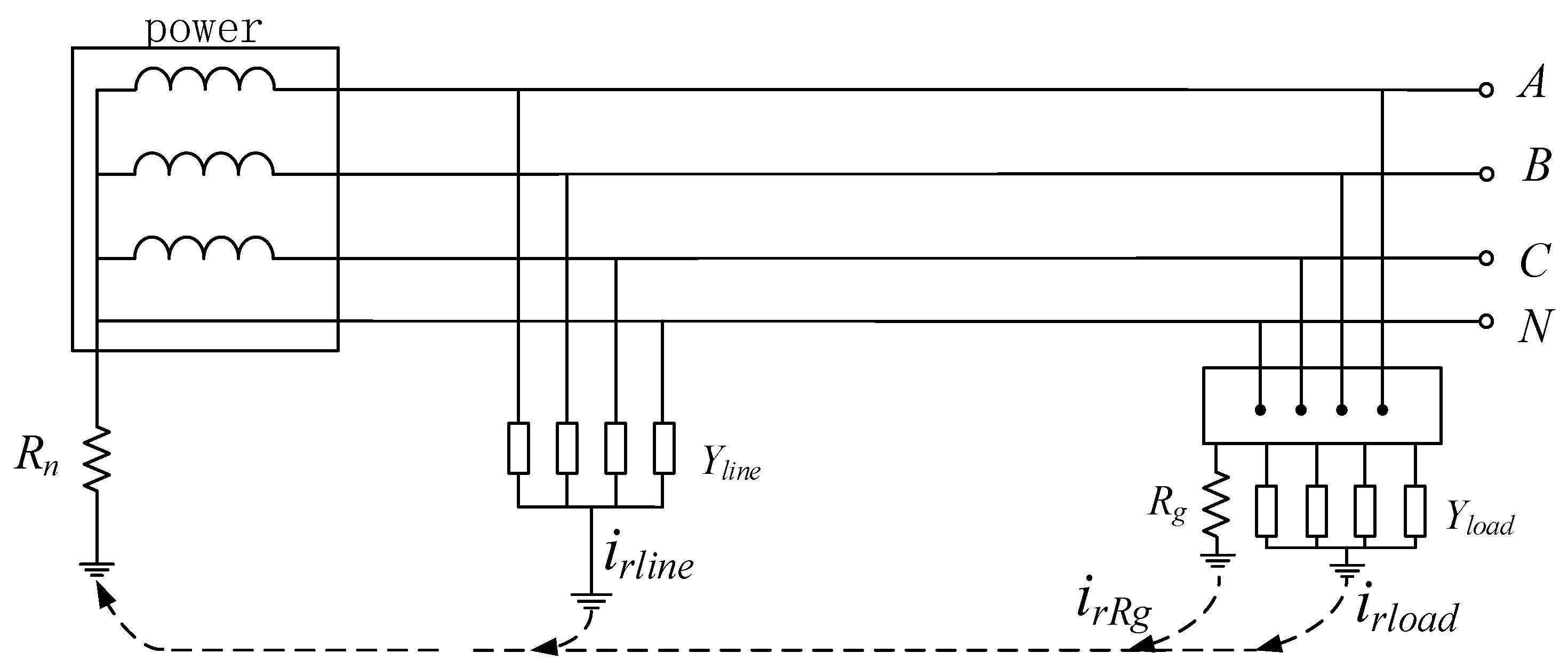
2.1. Generation of Residual Current from Unbalanced Systems

Residual currents emerge during regular operations due to line imbalances, asymmetric loads, and inadequate insulation at junction points. For instance, in the TT configuration, the asymmetry in ground conductivity results in the generation of residual currents: irline along the line and irload and irRg on the load side. This phenomenon is depicted in Figure 1, where A, B and C represent three-phase power lines, and N is a neutral line.
In the low-voltage distribution station area, there are numerous lines where residual currents from rear equipment and lines accumulate in the front part. During normal system operation, the residual current behind household protection typically remains below 20 mA. In contrast, the capacitance current to the ground and equipment leakage current to the ground in medium and general protection can reach several hundred mA under standard conditions, posing challenges in setting up effective protection with poor sensitivity.
The short length of low-voltage distribution lines results in minimal ground capacitance and consequently very low residual currents generated on the line. However, the complexity of load-side equipment and electrical environments leads to significantly higher amplitudes of leakage current and an increased likelihood of leakage compared to the line itself. Therefore, the primary source of inherent residual current in low-voltage distribution networks is the terminal load. While most equipment leakages do not trigger the action threshold of household protection, the cumulative leakage from multiple loads results in excessive residual current accumulation in the front section before the user-side measuring box.

2.2. Generation of Residual Current from N-Phase Line Grounding

In the TN configuration, the neutral line is typically grounded on the load side. Illustrated in Figure 2 where A, B and C represent three-phase power lines, N is a neutral line, PE represent protecting earthing line, grounding the PEN line results in an increased current irRg flow at the location, significantly elevating the inherent residual current at the upstream protection. Apart from the fault residual current, the neutral current returning to the power supply side through the repeated grounding point also contributes to an increase in the normal residual current. The measured normal residual current on the power supply side can reach several amperes, surpassing the predetermined threshold by a considerable margin.
Moreover, irRg experiences substantial fluctuations during load switching, rendering it unfeasible to install a residual current protection device before the grounding point in such systems. The repeated earthing point in TN configurations is typically situated at the terminal pole or entry container, concentrating the inherent residual current loop at the end of the line (load side).

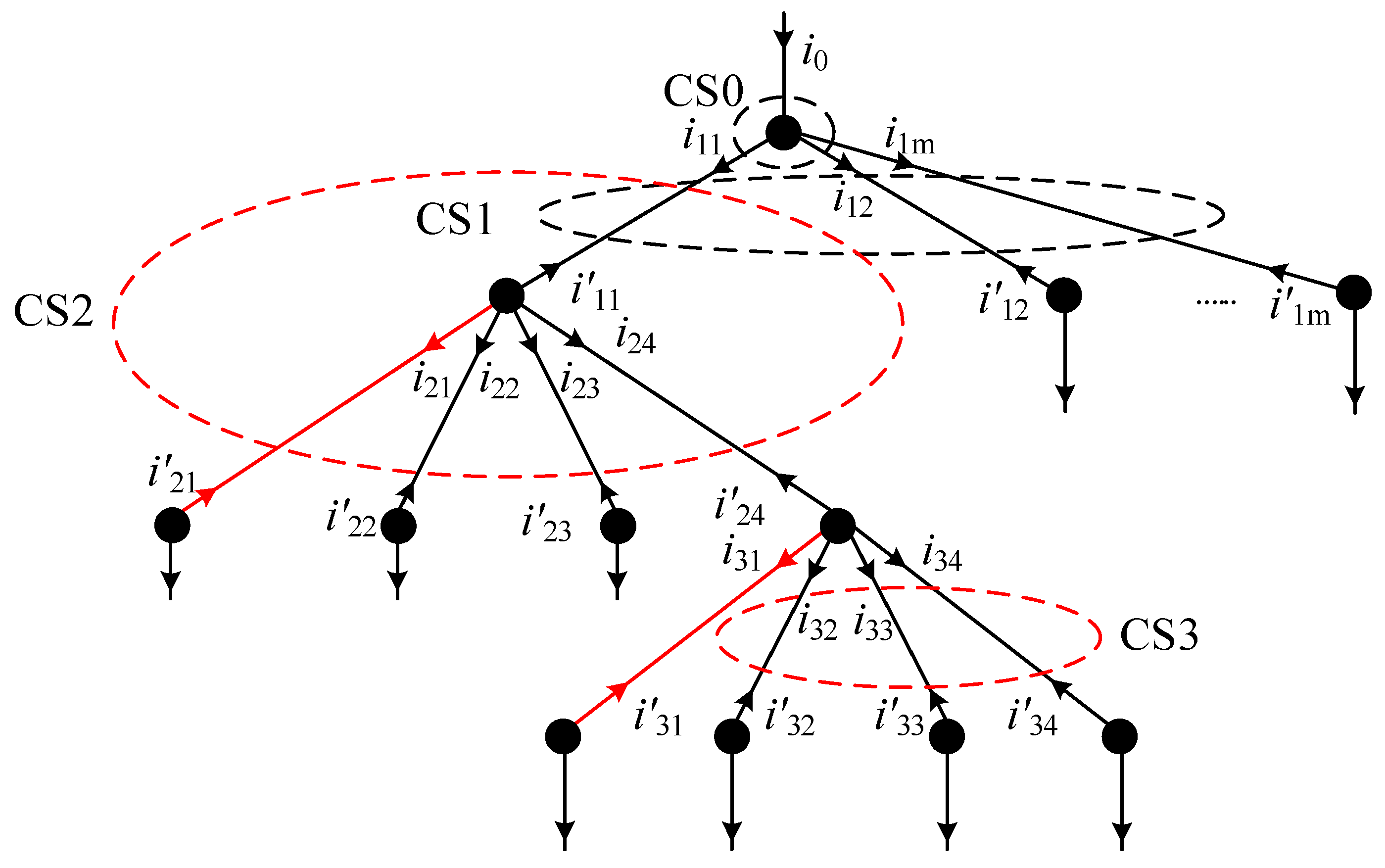
3. Distributed Residual Current Protection Utilizing Closed-Section Methods

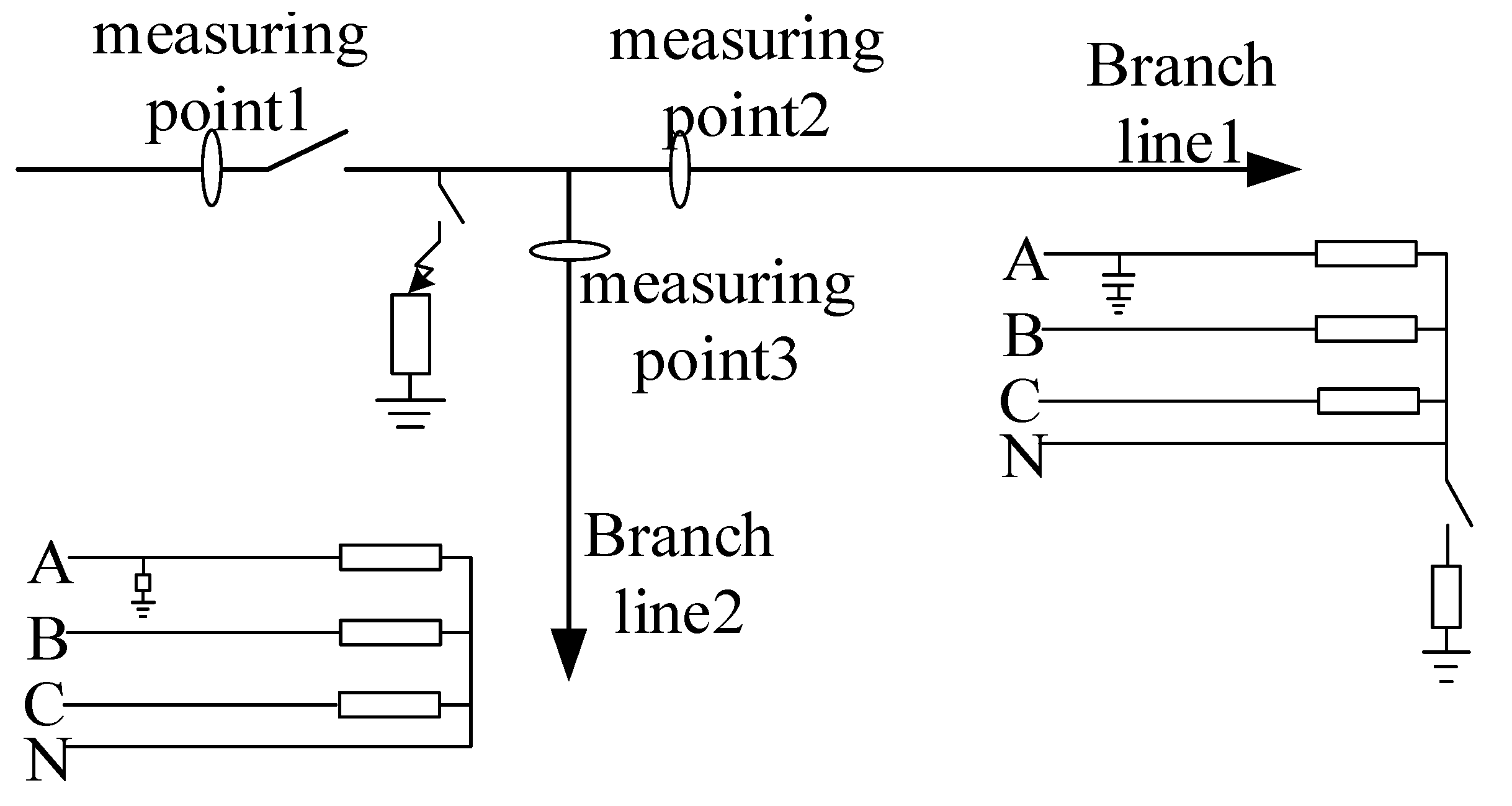
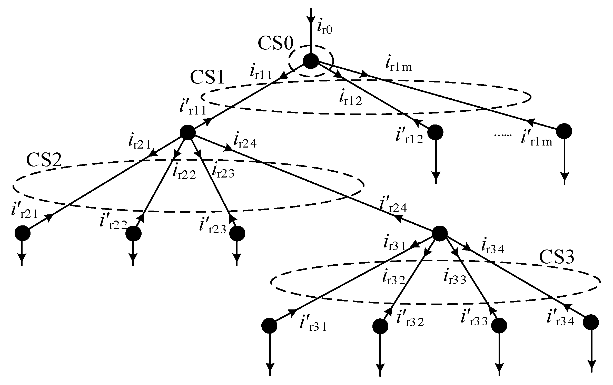
3.1. Protection Principle

The application of graph theory serves to streamline the topological connectivity within the low-voltage distribution network, facilitating the creation of a minimal closed-section area on the topology diagram. Within this designated area, all external contact points are equipped with Line Terminal Units (LTUs) and are incapable of further subdivision. The residual current at these external contact points is quantifiable, with all currents at these points adhering to Kirchhoff’s law. This concept is visually represented in Figure 3.
Δ I ˙ CS 0 = I ˙ r 0 + I ˙ r 11 + I ˙ r 12 + + I ˙ r 1 m
Δ I ˙ CS 1 = I ˙ r 11 + I ˙ r 12 + + I ˙ r 1 m + I ˙ r 11 + I ˙ r 12 + + I ˙ r 1 m
Δ I ˙ CS 2 = I ˙ r 21 + I ˙ r 22 + I ˙ r 23 + I ˙ r 24 + I ˙ r 21 + I ˙ r 22 + I ˙ r 23 + I ˙ r 24
Δ I ˙ CS 3 = I ˙ r 31 + I ˙ r 32 + I ˙ r 33 + I ˙ r 34 + I ˙ r 31 + I ˙ r 32 + I ˙ r 33 + I ˙ r 34
It is evident that during normal operations, the residual current within the closed section is limited to the residual current within its designated protection range. However, following an earth fault (leakage), the residual current increases significantly, with almost all of it representing the fault branch current. Consequently, the protection settings can be set at a very low threshold, significantly enhancing sensitivity.
For instance, considering general protection at the transformer outlet, its residual current comprises the cumulative inherent residual of the entire substation area. In contrast, for CS0 utilizing data measured at the same location, its residual current is solely attributed to the inherent residual current on the bus within the substation area. In scenarios involving the TN configuration with repeated earthing of the neutral point on the load side, a judicious selection of the closed section can effectively address the challenge of installing residual current protection. An illustrative example is provided in Figure 4, where A, B and C represent three-phase power lines, N is a neutral line, PE represent protecting earthing line.
The external connection point of the closed section is set before the repeated earthing point of the TN-C-S configuration. The residual current of the closed section composed of the residual current measured by the two points P1, P2, and P3 can be calculated as
Δ I ˙ P = I ˙ rP 1 + I ˙ rP 2 + I ˙ rP 3
In Equation (5), during normal operation, Δ I ˙ P does not include the current through the grounding point of the N line and the residual current generated by the load. Repeated earthing does not affect the sensitivity of the distributed residual current protection and can achieve reliable earth (leakage) fault protection.

3.2. Protective Criterion Design

Referring to the method of differential protection setting [3,4,5,6,7,8], Equation (6) gives a distributed residual current protection criterion.
I d > K I res I d > I set
In the formula, K is the ratio braking coefficient; Id and Ires are the operating current and braking current, respectively; Iset is the minimum operating current. The first criterion is the action criterion; the second is the protection initiation criterion.
The expressions for Id and Ires are as follows:
I d = | i = 1 N I ˙ i | I res = i = 1 N | I ˙ i |
I ˙ i represents the residual current phasor measured by the device at the external contact point of the closed section, this paper sets the direction of the current flowing into the closed section as positive and the outflow as negative.
Iset is usually selected in two ways:
(1) It must exceed the maximum unbalanced current when externally grounded. We obtain the following:
I set = K rel K np K er K st I kmax
Krel is the reliability coefficient, which is taken as 1.2~1.3; Knp is the aperiodic component coefficient, which is taken as 1; Ker is the 10% error coefficient of the current transformer; Kst is the coefficient of the same type of transformer, and it is taken as 0.5 when the current transformer is of the same type; Ikmax is the maximum short-circuit current flowing through the current transformer when it is externally grounded.
(2) It must exceed the maximum inherent residual current in the closed section. We obtain the following:
I set = K rel I rmax
Krel is the reliability coefficient taken as 1.2~1.3; Irmax is the maximum residual current during normal operation in the closed-section protection.
The design of the distributed residual current protection criterion is described in matrix form. First, the number of LTUs in the protection and the number of closed sections are determined. It is assumed that there are N LTUs and M closed sections in the protection. A relationship matrix R is defined to represent the relationship between the closed-section CS and LTU, and it is expressed as
R = r 11   r 12   r 1 N r 21   r 12   r 2 N               r M 1 r M 2 r M N
In the matrix, the number of rows is equal to the number of closed sections, the number of columns is equal to the number of LTUs, and rij (i = 1, 2, …, N; j = 1, 2, …, M) represents the relationship of each LTU in the closed section; rij has three states:
r i j = 1 r i j = 0 r i j = 1
rij = 1 means that the LTU is associated with the closed section, that is, the LTU is the external contact point of the closed section, and the current is for the inflow; rij = 0 means that the LTU is not associated with the closed section; rij = −1 means that the LTU is associated with the closed section, and the current is for the outflow.
The residual current matrix measured by each LTU is defined as I ˙ rLTU , and the element in it, which is the residual current phasor measured by each LTU, is recorded as I ˙ r n (n = 1, 2, …, N), which can be expressed as
I ˙ rLTU = I ˙ r 1 I ˙ r N T
The residual current matrix of the closed section is recorded as Δ I ˙ CS m (m = 1, 2, …, M), which is given by
Δ I ˙ CS m = Δ I ˙ CS 1 Δ I ˙ CS M T
According to the definition of the relationship matrix, the matrix R, I ˙ m 1 , Δ I ˙ m 1 satisfies the following:
Δ I ˙ CS m = R I ˙ rLTU
Taking the absolute value (modulus value) of the elements in the matrix Δ I ˙ CS m as the current action matrix, denoted as Δ I ˙ CS d , it is expressed as
Δ I CS d = | Δ I ˙ CS 1 | | Δ I ˙ CS M | T
The braking relationship matrix is defined as Rres. Rres is the absolute value of the elements in the relationship matrix R, which can be expressed as
R res = | r 11 |   | r 12 |   | r 1 N | | r 21 |   | r 12 |   | r 2 N |               | r M 1 | | r M 2 | | r M N |
According to the definition of the braking relation matrix, the braking current matrix is expressed as
I CSres = R res | I ˙ CS m |
Defining the protection minimum operating current matrix as I CSset , the elements in it are recorded as I CSset m (m = 1, 2, …, M) and I CSset m can be expressed as
I CSset = I CSset 1 I CSset M T
The elements in Equation (18) are set according to Equations (9) and (10). Each row in the above matrix represents a closed section, and (15), (17), (18) are put into (6), and the matrix representing whether the operating current exceeds the limit can be obtained, which is defined as D. The limit matrix D is expressed as
D = [ D 1 D i D M ]
The element Di (i = 1, 2, …, M) in the matrix has two states according to whether the closed-section action current exceeds the limit:
D i = 1 D i = 0
Di = 1 indicates that the operating current exceeds the limit; Di = 0 means the operating current does not exceed the limit.
Under normal operation, the elements in the limit-crossing matrix D are all 0. After the residual current of the closed section exceeds the limit, the corresponding element becomes 1.

3.3. Blocking and Tripping of Protection

The surplus residual current within the closed section may not always stem from a ground fault within that specific section. Abnormalities in the residual current CT at the external contact point of the closed section or malfunctions in the protection device can lead to anomalous data measurements, consequently resulting in excess residual current within the section. To mitigate the risk of protection system malfunctions, a protective blocking matrix denoted as B is defined, with the corresponding expression outlined as follows.
B = B 11 0 0 B M M
The protection blocking matrix B is an M-dimensional diagonal matrix, and its diagonal elements Bii (i = 1, 2, …, M) have two states.
B i i = 1 B i i = 0
Bii = 1 means that all external contact point devices in the closed section operate normally; Bii = 0 means that the device on one or more external contact points in the closed section is detected as abnormal, and the protection should be blocked.
Define the protection trip matrix as T, and the expression is as follows.
T = [ T 1 T i T M ]
Ti (i = 1, 2, …, M) in the matrix has two states according to whether the protection acts or not.
T i = 1 T i = 0
Ti = 1 means that in the corresponding closed-section protection, the switch trips; Ti = 0 means that the switch does not trip. The relationship between T, D, and B is as follows:
T = D B

3.4. Adaptive Expansion of Closed Sections

In instances where the residual current protection device malfunctions or is inactive, the closed section associated with the device no longer adheres to Kirchhoff’s law, leading to the blocking of the corresponding closed-section protection. Consequently, adjustments must be made to the closed protective section to either safeguard the initial closed-section range or minimize the unprotected area. The schematic illustrating the self-adaptive expansion of the closed section is depicted in Figure 5.
(1) Expansion of Closed Sections: In cases where one or more protection devices within the closed section upstream of a line exhibit abnormalities, the closed-section protection can be enlarged to encompass the original closed section within the protection scope. As illustrated in Figure 5, if the upstream measurement or protection device for line L21 malfunctions, rendering the current ir21 unmeasurable, the residual current measurement at the rear of the line remains intact. To address this, the closed section CS2 extends its protection range by incorporating line L21 and merging it into a new CS2. This adjustment maintains the system’s actual protected area as unchanged.
(2) Unexpandable Closed Sections: When the protection device at the boundary (end of the line) in the power distribution system malfunctions, preventing residual current measurement at other points, and hindering continued protection, the original closed section must be reduced. However, efforts should be made to minimize the unprotected area. For instance, if the measurement device behind line L31 malfunctions, rendering the line unprotected, line L31 is excluded from the protection range of the initial closed section CS3 and designated as a new closed-section protection CS3.

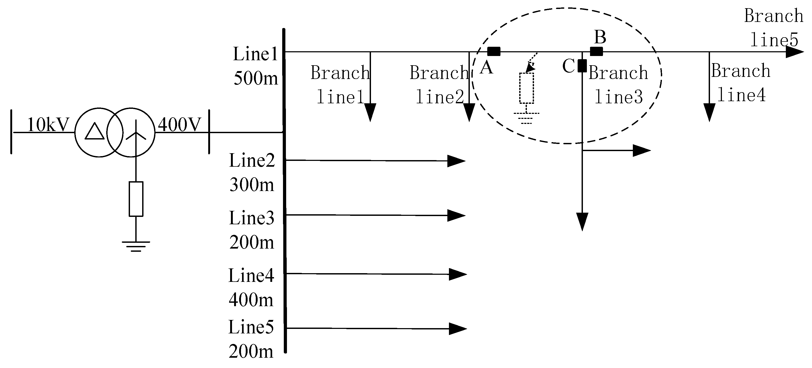
4. Simulation Analysis

4.1. Selection of Simulation Model and Parameters

The earth fault simulation model of the low-voltage distribution network is depicted in Figure 6. The system comprises a 10 kV/0.4 kV distribution station area with five outgoing cables, and the transformer is connected in a ∆/Y configuration. The grounding resistance of the neutral point system on the low-voltage side is set at 4 Ω [9]. Altering the wiring configuration on the load side results in a variation in the grounding system employed. The residual current protection devices are set in positions A, B and C to structure a closed section.
The simulation model includes five outgoing lines, with line 1 serving as a test simulation line spanning 500 m. Distributed along the line are five branches, each evenly spaced and varying in length from 50 to 100 m. Branch 3 features two secondary branches within it. The parameters of the lines and transformer are shown in Table 1. Operating at approximately 70% of the load, the total system load corresponds to 70% of the transformer capacity [9]. Line 1 bears a load of 200 kVA, evenly distributed across its branches, with each branch carrying 40 kVA and the secondary branch supporting 20 kVA. The power factor across the system is maintained at 0.95. Lines 2–5 collectively carry a load of 170 kVA, with the same power factor as line 1. The simulation parameters in ATP-EMTP are configured with a step size of 10 us and a sampling frequency of 10 kHz/s.

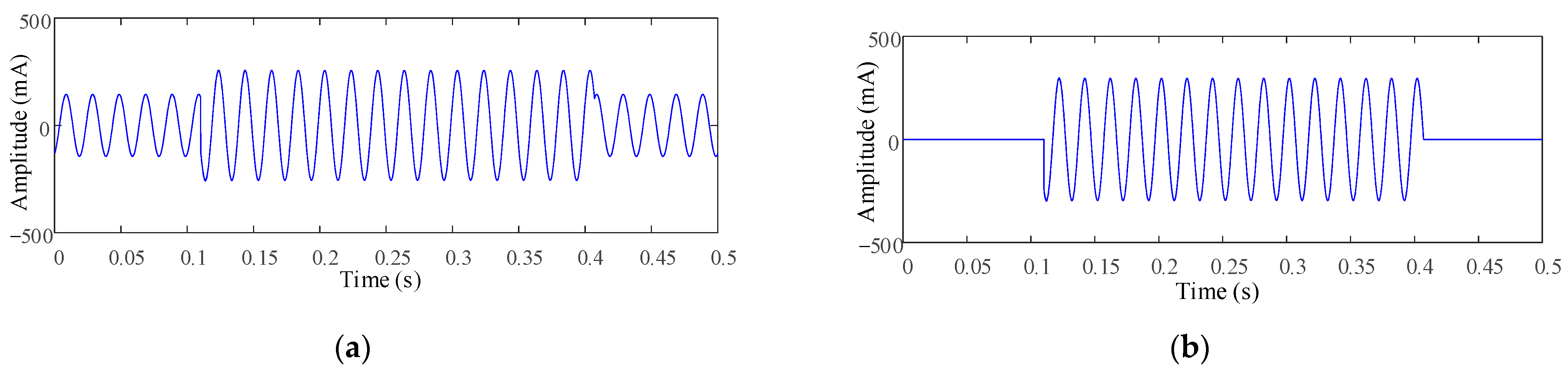
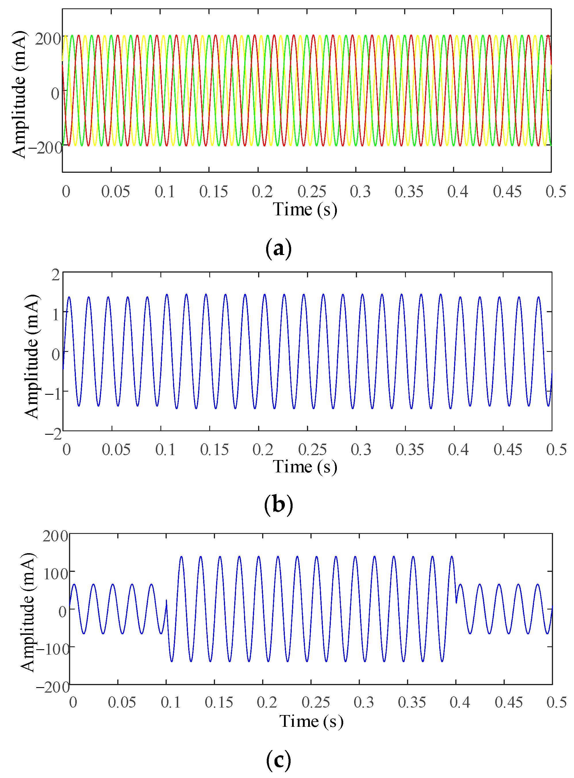
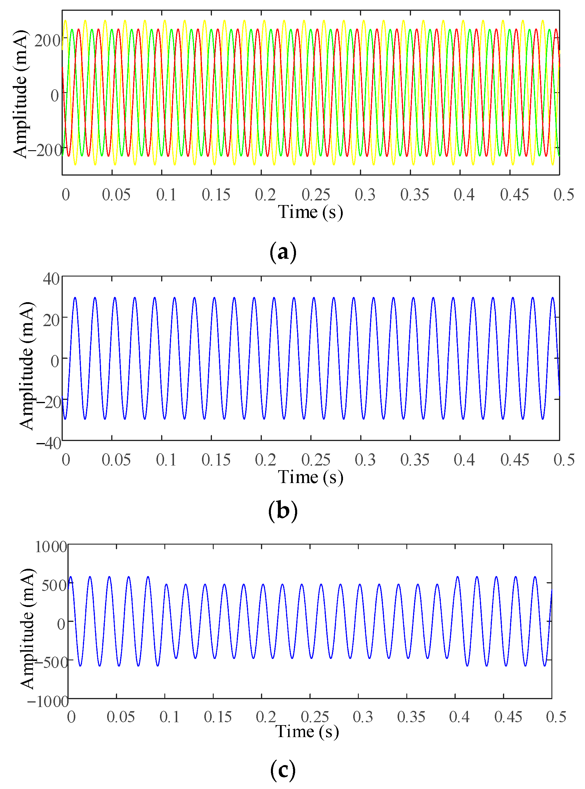
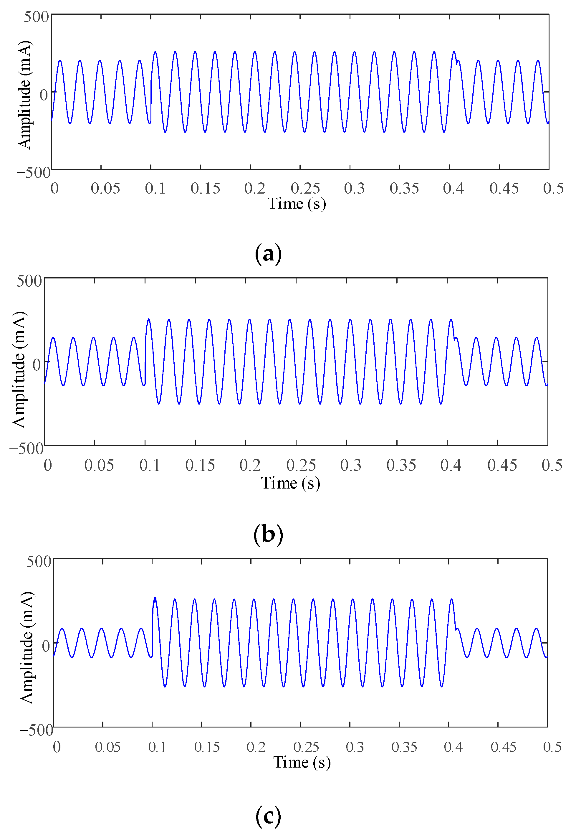
4.2. Analysis of Simulation Results

4.2.1. TT Configuration Ground Fault Analysis

Within the simulation model, an earth fault is induced at the termination of phase A on line 1, with a fault resistance of 1 kΩ. To facilitate a comprehensive comparison, the inherent residual current of line 1 is standardized at 200 mA, uniformly distributed along both the line and the load. The residual current levels at the beginning, middle, and end of the line during the occurrence of the earth fault are meticulously recorded. The outcomes of this analysis are visually presented in Figure 7.
From Figure 7, it is evident that the inherent residual current decreases as it nears the end of the line, with the residual current close to 200 mA at the head end and minimal mutation of the residual current post fault. Traditional residual current protection methods such as amplitude comparison and protection techniques relying on amplitude and phase discrimination based on the residual current amplitude prove to be largely ineffective. This observation underscores the challenges of activating intermediate and general protection upstream of the site and the issue of low sensitivity. Notably, closer to the end position, where the inherent residual current is lower, the mutation in the residual current amplitude due to a fault becomes more pronounced, showcasing improved performance with the existing protection methods.
An earth fault is introduced in the middle phase of line 1 with a grounding resistance of 1 kΩ. The closed section for residual current, as depicted in Figure 6, is established with terminals at positions A, B, and C, and the corresponding waveform data are presented in Figure 8.
Upon comparing subfigures (a) and (b), it becomes apparent that the residual current within the closed section remains minimal in the absence of faults. Following a fault occurrence, the fault current is more accurately reflected, effectively mitigating the impact of the inherent residual current and relying solely on the upstream monitoring point. It is evident that the single-point residual current protection method lacks sensitivity compared to closed-section residual current protection, as the amplitude current experiences insignificant changes pre and post fault. Notably, the residual current amplitude after the fault in Figure 8a is measured as 255 mA, while in Figure 8b, it reaches 296 mA. By combining the inherent residual current with the fault current, a partial cancellation occurs, reducing the fault current amplitude. This aligns with the earlier observation that the phase angle of the fault current is arbitrary. Consequently, the closed-section residual current protection demonstrates higher reliability and resistance to transitional variations.

4.2.2. TN Configuration Ground Fault Analysis

The three-phase symmetry and asymmetry are set on the load side of the TN configuration of the simulation model. The fault is set in the middle phase of line 1, and the fault resistance is 1 kΩ. The magnitude of the residual current at the outlet of the line and its increase with the load asymmetry are recorded and compared. In the case of a symmetrical load, the three-phase current, neutral line current, and residual current waveform at point A in the middle of outgoing feeder one and the residual current of the closed section are shown in Figure 9. In (a), the three-phase currents are equal, and it can be seen that the load of line 1 is symmetrical. However, it can be seen in (b) that even in the case of a symmetrical load, there is still a current of 1 A on the neutral line, which is caused by the asymmetry of line parameters and power supply (three-phase power supply), the line is a symmetrical four-wire system in physical parameters, but the mutual impedance between the lines is not the same, so the current will also be generated on the neutral line under the condition of the symmetrical operation of the load. It can be seen from (c) that the load is symmetrical, and the residual current will also be generated when the impedance to the ground is symmetrical, which is the reason why the TN-C configuration cannot install the residual current.
The load symmetry of branch 3 is changed. The three-phase current at point A, the current flowing through the neutral line, and the residual current at point A are shown in Figure 10. After the phase A current increases, the amplitude of the current flowing on the neutral line increases to nearly 30 mA, and the inherent residual current amplitude at point A also increases to nearly 500 mA. Therefore, the inherent residual current in the TN-C configuration changes with the load symmetry, and the traditional method cannot achieve protection.
The calculated residual current of the closed section under the two faults is shown in Figure 9 and Figure 10, respectively, and the waveform is shown in Figure 11, where (a) is the residual current of the closed protective section when the load is symmetrical, and (b) is the load asymmetry. The closed-section residual current at this time shows phase asymmetry.
It can be seen from Figure 11 that the load symmetry of the two faults is inconsistent. The inherent residual current of the system is also different because the repeated earthing point on the load side is excluded from the closed section when constructing the closed section. The residual current of the closed section is almost only related to the transition resistance when the earth fault occurs in the closed section. The transition resistances corresponding to the two faults in the figure are both 1 kΩ, so the calculated residual current of the closed section is the same. The residual current has obvious variation characteristics, not affected by the residual current before the fault. It can be proved that the closed-section residual current protection method can also achieve effective earth fault protection for the TN-C configuration in the low-voltage distribution network, which provides a reference solution for the current TN-C configuration problem not to be equipped with the residual current protection function.

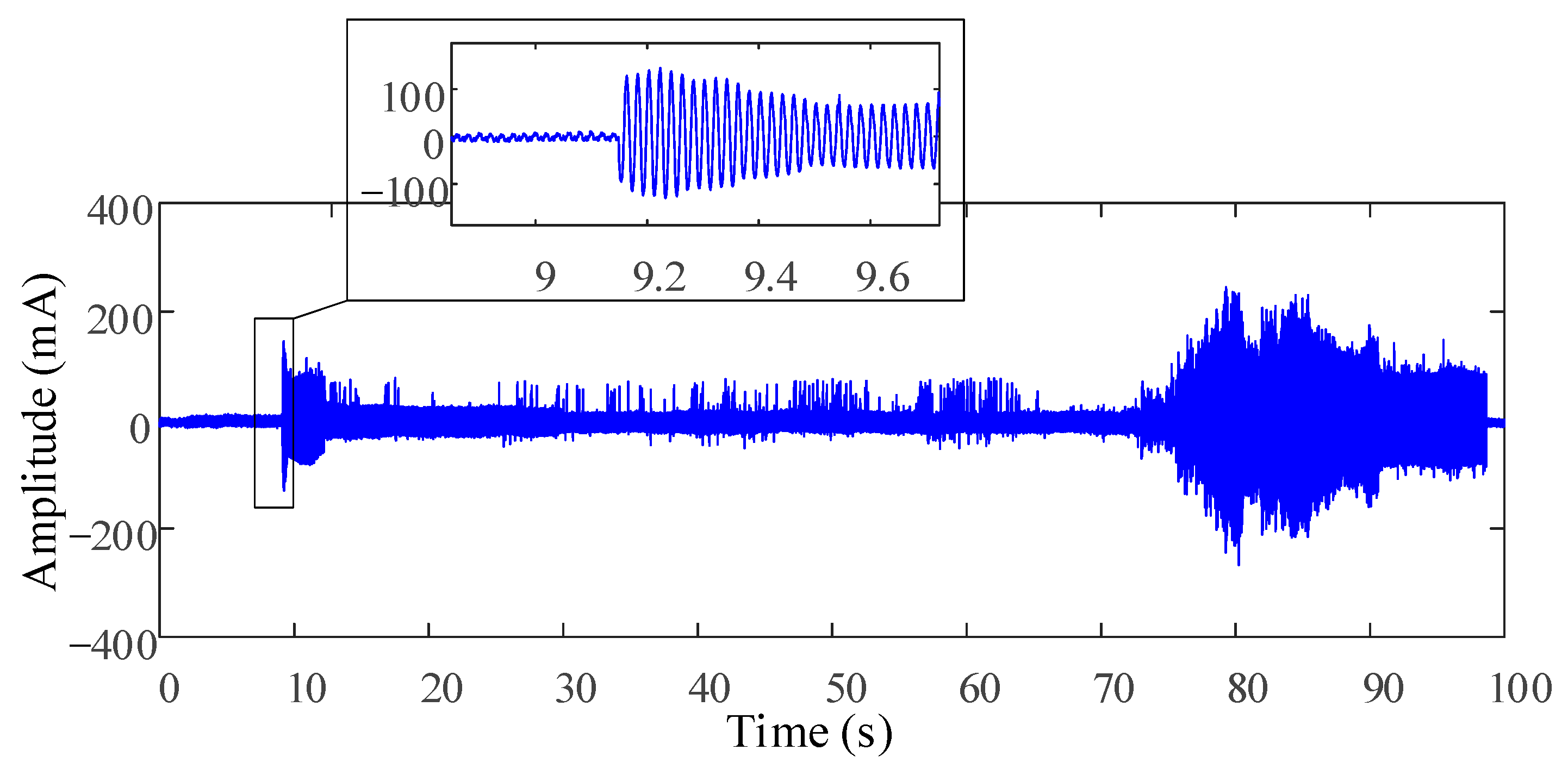
5. Analysis of Experimental Data

The methodology for selecting the single-phase earth fault line device was implemented in a laboratory simulation test of leakage faults within a low-voltage distribution network at a university in Shandong Province. The transformer-related parameters are the same as those of the data in Section 4.1, shown in Table 1. The circuit structure setup for the test is depicted in Figure 12, where a simulated low-voltage line with a single branch is utilized, and a fault is induced upstream of the branch. Residual current values are measured at points 1, 2, and 3, followed by the construction of the residual current within the closed section. A comparative analysis is then conducted to assess the differences in residual current protection at measuring point 1.
The simulation encompasses the TT, TN-C, and TN-C-S configurations, distinguishing between grounded and ungrounded neutral points on the load side. Grounding is achieved through a grounding pin with a resistance to ground below 100 Ω, meeting the necessary criteria. The presence of repeated earthing points contributes to an escalation in inherent residual current levels. For experimental purposes, in the simulation of the TN-C and TN-C-S configurations, only the neutral point of branch 1 on the load side is grounded, while branch 2 remains ungrounded. This selective grounding approach does not compromise the efficacy of the algorithm verification process.

5.1. Earth Fault Testing in TT Configuration

The ground fault test results are illustrated in Figure 13, showcasing the recorded waveform of the fault process in its entirety (a) and a magnified view (b). Channel 1 displays the residual current waveform of measurement point 1, while channels two and three exhibit the residual current waveforms of measurement points 2 and 3. During the test, a current transformer (with the load being resistance) is employed to measure the residual current, with the unit of measurement in millivolts (mV).
The initiation of the fault is indicated in Figure 13a, revealing that post fault, there is minimal change in the residual current amplitude at measurement point 1. Subsequently, upon the introduction of saltwater at the fault location, arc fault characteristics manifest, as depicted in Figure 13b. Notably, the residual current at measurement point 1 exhibits a distinct current arc-extinguishing (zero breaks) feature at the zero-crossing point. Figure 14 illustrates the computation of the residual current within the closed section established by the three measurement points.
In Figure 14, in the absence of faults, the residual current amplitude remains below 10 mA. However, following the fault occurrence, the fault residual current surges to 126 mA, representing a noticeable increase. The discernible change in the residual current amplitude post fault highlights the reliable detection of earth faults based on the residual current value within the closed section.

5.2. Ground Fault Testing in TN Configuration

The ground fault test in the TN configuration involved grounding the neutral point of branch 1, eliminating the grounding capacitor responsible for residual current in the A-phase, and removing the B-phase load in branch 1 to induce three-phase load imbalance. The fault point was positioned on damp ground to record the residual current at measurement points 1, 2, and 3, along with the current flowing through the ground wire of branch 1 post fault.
Figure 15 reveals the dynamic nature of the fault impedance fluctuations throughout the fault process. Notably, the current amplitudes in channel 2 and channel 4 are identical, indicating that the inherent residual current on branch 1 primarily originates from the current at the grounding point. This observation substantiates the source of inherent residual current in the TN-C and TN-C-S configurations, elucidating the challenges in installing residual current protection. In Figure 15b, a magnified view of (a) depicts a scenario where the primary fault resistance gradually changes, underscoring the limitations of existing protection methods when dealing with minimal current levels.
Figure 16 illustrates the residual current within the closed section established by measurement points 1, 2, and 3, as depicted in Figure 15. This aligns with the observations from the TT configuration test. Prior to the fault occurrence, the residual current within the closed section remains minimal, enabling it to effectively reflect the fault current post fault. Consequently, the residual current protection method remains unaffected by the inherent residual current of the system and can be successfully implemented in both the TN-C and TN-C-S configurations.
The experiments above demonstrate the sensitivity of the proposed distributed residual current protection method based on closed sections. In practical applications, it is necessary to clarify the network topology of the low-voltage distribution network, construct closed sections by multiple LTUs, obtain the current matrix and detect possible grounding (leakage) faults according to the set threshold. However, further discussion is needed on how to adaptively adjust the threshold when considering complex scenarios such as an unknown network topology or choice of LTU installation location.

6. Conclusions

In summary, this study presents a novel distributed residual current protection method based on closed sections, which addresses the inherent challenges in low-voltage distribution networks. Through a comprehensive analysis and extensive simulations coupled with field tests, we have demonstrated that our proposed method significantly enhances the sensitivity and reliability of fault detection in these networks. By calculating the phasor sum of residual currents at each external contact point within a closed section, we mitigate the impact of inherent residual current and ensure high protection sensitivity independent of the device’s location.
Our approach not only improves the accuracy of fault localization but also offers a more flexible and adaptable solution compared to traditional protection methods. The successful implementation of multiple RCDs across sub-circuits, as opposed to a single general RCD at the entry point, highlights the potential for increased safety and efficiency in power distribution systems. Furthermore, the method’s applicability to both TN-C and TN-C-S systems, as evidenced by the simulation and field experiments, underscores its versatility and adaptability to various network configurations.

Author Contributions

Conceptualization, X.Z., Y.L. and H.Z.; methodology, X.Z.; software, X.Z.; validation, X.Z., Y.L. and H.Z.; formal analysis, Y.L. and H.Z.; investigation, X.Z.; resources, Y.L.; data curation, X.Z.; writing—original draft preparation, X.Z.; writing—review and editing, Z.H. and H.Z.; visualization, X.Z.; supervision, H.Z.; project administration, Y.L.; funding acquisition, H.Z. All authors have read and agreed to the published version of the manuscript.

Funding

This research was funded by the National Natural Science Foundation Smart Grid Joint Fund Integrated Project grant number U22B6008.

Data Availability Statement

The data presented in this study are available on request from the corresponding author. The data are not publicly available due to generating in our lab.

Conflicts of Interest

Author Yuanlong Liu was employed by the State Grid Shandong Electric Power Company. The remaining authors declare that the research was conducted in the absence of any commercial or financial relationships that could be construed as a potential conflict of interest.

Nomenclature

i rline Residual current along the line.
i rload Residual current on the load side.
i rRg Residual current of the shell on the load side.
Δ I ˙ CS i Residual current within the closed section i.
I ˙ r i j Residual current flowing into the closed section i.
I ˙ r i j Residual current flowing out of the closed section i.
I d Operating current.
I res Braking current.
I set Minimum operating current.
K Ratio braking coefficient.
I ˙ i Residual current phasor measured at the external contact point of the closed section.
K rel Reliability coefficient.
K np Aperiodic component coefficient.
K er 10% error coefficient of the current transformer.
K st Coefficient of the same type of transformer.
I kmax Maximum short-circuit current flowing through the current transformer.
I rmax Maximum residual current during normal operation in the closed-section protection.
R Relationship matrix between the closed-section CS and LTU.
r i j Relationship of each LTU in the closed section.
I ˙ rLTU Residual current matrix measured by each LTU.
I ˙ r n Residual current phasor measured by each LTU.
Δ I ˙ CS m Residual current matrix of the closed section.
Δ I ˙ CS d Current action matrix.
R res Absolute value of the elements in the relationship matrix R.
I CSres Braking current matrix.
I CSset Protection minimum operating current matrix.
I CSset m Elements in I CSset m .
D Limit matrix.
D i Elements in D.
B Protection blocking matrix.
B i i Diagonal elements in B.
T Protection trip matrix.
T i Elements in T.

References

  1. Zhao, H.; Xiao, X.; Sun, Q. Identifying Electric Shock in the Human Body via alpha Dispersion. IEEE Trans. Power Deliv. 2018, 33, 1107–1114. [Google Scholar] [CrossRef]
  2. Freschi, F. High-Frequency Behavior of Residual Current Devices. IEEE Trans. Power Deliv. 2012, 27, 1629–1635. [Google Scholar] [CrossRef]
  3. Li, K.; Lin, J.; Niu, F.; Wang, Y.; Li, Q.; Guo, Z.; Wu, Y. A Novel Fault Leakage Current Detection Method with Protection Deadzone Elimination. IEEE Trans. Instrum. Meas. 2021, 70, 3505009. [Google Scholar] [CrossRef]
  4. Kotsch, J.; Prussak, B.; Morse, M.; Kohl, J. Exploration of the Theory of Electric Shock Drowning. In Proceedings of the 2018 IEEE IAS Electrical Safety Workshop (ESW), Fort Worth, TX, USA, 19–23 March 2018; pp. 1–3. [Google Scholar]
  5. Harid, N.; Bogias, A.C.; Griffiths, H.; Robson, S.; Haddad, A. A Wireless System for Monitoring Leakage Current in Electrical Substation Equipment. IEEE Access 2016, 4, 2965–2975. [Google Scholar] [CrossRef]
  6. Wu, S.; Lin, S.-Y.; Guo, M.-F. Application of WE-AE-BP Method to Electric Shock Faults Identification in the Low-voltage Distribution Network. In Proceedings of the 2020 IEEE 1st China International Youth Conference on Electrical Engineering, Wuhan, China, 1–4 November 2020; pp. 1–6. [Google Scholar]
  7. Zhang, M.; Qin, P.; Chen, Y.; Jia, H.; Wang, Z.; Deng, W. Study on the Detection Method of Leakage in TN-C Area of Low-voltage Distribution Network. In Proceedings of the 2021 International Conference on Power System Technology, Fukuoka, Japan, 10–12 September 2021; pp. 378–381. [Google Scholar]
  8. Zhang, X.; Liu, Z.; Wang, Y.; Dou, Z.; Zhai, G.; Wei, Q. Residual Current Detection Method Based on Variational Modal Decomposition and Dynamic Fuzzy Neural Network. IEEE Access 2021, 9, 142925–142937. [Google Scholar] [CrossRef]
  9. Dou, Z.; Han, Q.; Niu, X.; Peng, X.; Guo, H. An Adaptive Filter for Aeromagnetic Compensation Based on Wavelet Multiresolution Analysis. IEEE Geosci. Remote Sens. Lett. 2016, 13, 1069–1073. [Google Scholar] [CrossRef]
  10. Dragomiretskiy, K.; Zosso, D. Variational Mode Decomposition. IEEE Trans. Signal Process. 2014, 62, 531–544. [Google Scholar] [CrossRef]
  11. Wang, Y.; Wai, R. Adaptive Fuzzy-Neural-Network Power Decoupling Strategy for Virtual Synchronous Generator in Micro-Grid. IEEE Trans. Power Electr. 2022, 37, 3878–3891. [Google Scholar] [CrossRef]
  12. Wang, Y.; Zhang, F.; Zhang, S. A New Methodology for Identifying Arc Fault by Sparse Representation and Neural Network. IEEE Trans. Instrum. Meas. 2018, 67, 2526–2537. [Google Scholar] [CrossRef]
  13. Shen, Y.-L.; Wai, R.-J. Wavelet-Analysis-Based Singular-Value-Decomposition Algorithm for Weak Arc Fault Detection via Current Amplitude Normalization. IEEE Access 2021, 9, 71535–71552. [Google Scholar] [CrossRef]
  14. Li, R.; Wong, P.; Wang, K.; Li, B.; Yuan, F. Power quality enhancement and engineering application with high permeability distributed photovoltaic access to low-voltage distribution networks in Australia. Prot. Control Mod. Power Syst. 2020, 5, 1–7. [Google Scholar] [CrossRef]
  15. Nsaif, Y.M.; Lipu, M.S.H.; Ayob, A.; Yusof, Y.; Hussain, A. Fault Detection and Protection Schemes for Distributed Generation Integrated to Distribution Network: Challenges and Suggestions. IEEE Access 2021, 9, 142693–142717. [Google Scholar] [CrossRef]
  16. Arrabe, R.G.; Granados, J.M.G.; Gomez, F.A.; Gaona, C.A.P. New Selective Directional Ground Fault Protection Method for Ungrounded Systems. IEEE Trans. Power Deliv. 2022, 37, 5234–5243. [Google Scholar] [CrossRef]
Figure 1. Schematic of inherent residual current of TT configuration.
Applsci 14 03256 g001
Figure 2. Schematic of inherent residual current of TN-C-S configuration.
Applsci 14 03256 g002
Figure 3. Schematic of distributed residual current protection.
Applsci 14 03256 g003
Figure 4. Schematic of distributed residual current protection of TN-C-S configuration.
Applsci 14 03256 g004
Figure 5. Schematic of self-adaptive expansion of closed section.
Applsci 14 03256 g005
Figure 6. Schematic of ground fault in low-voltage distribution network.
Applsci 14 03256 g006
Figure 7. Residual current distribution along the line during terminal leakage fault: (a) residual current waveform at the head end of line 1 in the TT configuration after the fault; (b) residual current waveform in the middle of line 1 in the TT configuration after the fault; (c) residual current waveform at the end of line 1 in the TT configuration after the fault.
Applsci 14 03256 g007
Figure 8. Residual current waveforms upstream of the earth fault closure section and its interior: (a) residual current waveform at the head end of line 1 of the TT configuration after the fault; (b) residual current waveform of the closed section.
Applsci 14 03256 g008
Figure 9. Earth fault under symmetrical load in TN configuration: (a) three-phase current waveform at point A; (b) neutral current at point A; (c) residual current at point A.
Applsci 14 03256 g009
Figure 10. Earth fault under asymmetrical load in TN configuration: (a) three-phase current waveform at point Al; (b) neutral current at point A; (c) residual current at point A.
Applsci 14 03256 g010
Figure 11. The closed−section residual current of TN−C configuration: (a) the case where the load is symmetrical; (b) the case of load asymmetry.
Applsci 14 03256 g011
Figure 12. Schematic of the test case.
Applsci 14 03256 g012
Figure 13. High impedance and unstable ground fault recorder: (a) recorded waveform; (b) partial view.
Applsci 14 03256 g013
Figure 14. Residual current waveform of unstable fault closed section.
Applsci 14 03256 g014
Figure 15. High impedance and unstable earth fault recorder: (a) recorded waveform; (b) partial view.
Applsci 14 03256 g015
Figure 16. Residual current waveform of closed section.
Applsci 14 03256 g016
Table 1. The parameters of main equipment.
EquipmentTypesParameters
Transformer10 kV/0.4 kVConfiguration: ∆/Y
Capacity: 1250 kVA
No-load loss: 1.36 kW
No-load current percentage: 0.27%
Short-circuit loss: 12 kW
Short-circuit voltage percentage: 4.5%
Power line YJV-0.6/1 kVConductor cross-section: 16 mm
Direct current resistance: <1.15 ohm/km
Carrying capacity: 100 A
Disclaimer/Publisher’s Note: The statements, opinions and data contained in all publications are solely those of the individual author(s) and contributor(s) and not of MDPI and/or the editor(s). MDPI and/or the editor(s) disclaim responsibility for any injury to people or property resulting from any ideas, methods, instructions or products referred to in the content.

