1. Introduction
The requirement for the accuracy of the spatial position of the railway track is based on the Czech technical standard (ČSN) 73 6360-2 (2013) [
1], Article 6.4.1, which specifies, among other things, that “the absolute lateral positional deviation of the track axis from its design position shall not be greater than ±10 mm when accepting work in the rail with the placing of new material, ±15 mm with the placing of used material, and when accepting other work shall not be greater than ±20 mm, while the mutual deviation of the lateral distance between the track axis and the platform edge shall be maintained within <−0;+20> mm from the design nominal position value”. The technical standards assume the invariance of the reference system, which is very difficult to ensure under operating conditions. Therefore, it is necessary to use proven precise measurement procedures that allow long-term repeatability and reproducibility of results.
Real-time technologies of Global Navigation Satellite Systems (GNSS) are very effective for precise positioning, as they allow for higher accuracy in the positional component than conventional terrestrial methods, even at a length of 1 km. In addition, they are efficient and easy to use due to the high degree of automation of the measurement process.
To achieve the required high sub-centimeter accuracy, a phase signal and two GNSS instruments (reference and rover) are required. Ideally, a network of permanent stations should be used if they are available in the area. Accuracy of less than 1 cm using only one GNSS device in real time is not yet realistic. For the real-time kinematic PPP method, although the algorithms are constantly improving, longer observation times of hours are required, e.g., 3 h, and the accuracies achieved are in the range of 2.5–5 cm in the horizontal component and around 10 cm in the elevation component [
2,
3], which are insufficient for accurate measurements on railways. The use of low-cost solutions further reduces the accuracy to a few decimeters [
4].
The horizon required for GNSS measurements is blocked by obstacles along the railway line. Obstacles that cause horizon blocking in non-urban areas are mainly nearby vegetation (trees, bushes), as well as construction objects and nearby buildings in urban areas.
An innovative solution for precise absolute measurement of the center of the track based on the integration of GNSS, inertial navigation system (INS) and odometer is presented in [
5]. The GNSS/INS/odometer system does not depend on a high-precision measurement network along the line, and, unlike conventional methods, it can operate in mobile measurement mode with measurement speeds ranging from 0.15 km/h to 5 km/h. Test results on the Zhengzhou−Xuzhou high-speed railway line showed that the measurement errors were less than 6 mm in the horizontal direction and 11 mm in the vertical direction, and the measurement system is capable of maintaining high accuracy within 5 cm, even in the event of a GNSS failure for 700 s.
To determine the geometric parameters of the track, a mobile measurement platform with two GNSS receivers was used to determine the basic vector, and this measurement system was supplemented with an inertial measurement unit (IMU) [
6]. The measurement platform enables determining the direction of the track and the longitudinal and transversal inclination angles. This makes it possible to verify the track geometry in the horizontal plane, i.e., to locate straight sections, transition curves and constant-radius curves. The measurement results were shown to be repeatable despite the dynamic interaction between the track and the measurement platform. The results confirmed the usefulness of the applied GNSS and IMU signal processing method for monitoring the geometrical parameters of the railway line under operational conditions.
The RTKRCV method and the RTKLIB computational library for ROS [
7] have been developed for the application of the RTK method using multiple GNSS receivers. This opens the possibility to develop complex GNSS systems consisting of several GNSS receivers using ROS. The combination of multiple GNSS receivers allows for more efficient determination of position, azimuth, velocity and tilt. The benefits are particularly evident when measuring moving objects.
Consistency assessments of GNSS satellite measurements and conventional track tacheometric measurements are covered in [
8]. The authors present the results of a comparative analysis of measurements made on a selected test section characterized by rather unfavorable conditions for both tacheometric and GNSS measurements. The tacheometric method was found to be more accurate than the kinematic GNSS method for determining the track axis. The agreement between the two methods was within a standard deviation of 10 mm. Optimal GNSS data acquisition frequencies were recommended for specific speeds of the measurement vehicles.
Ensuring availability and reliability of positioning, especially in places with limited access to satellite signal (in tunnels, in areas with dense concentration of buildings and in forest areas), was solved by combining GNSS and inertial system with RTK receiver support and the Ekinox2-U system was developed [
9]. The Ekinox2-U system can meet the positioning accuracy requirements for rapid inventory of existing rails up to 3 cm (
p = 0.95), as well as design and construction works with the required accuracy up to 10 cm (
p = 0.95). On the other hand, the system cannot be used to determine the location and extent of track deformation with the required accuracy of up to 1 cm (
p = 0.95).
The use of a special KRAB trolley for continuous monitoring and analysis of the quality of the track geometry in the transition zone is discussed in [
10]. In transition zones, where different construction materials interact, deformations occur and need to be monitored. The absolute position on the track was determined by a GNSS sensor mounted on the KRAB device, and a precise relative measurement based on the short-fixed chord principle was performed by the KRAB device. The measurements were linked to a precise geodetic network built along the line.
Optimization of GNSS measurement method selection using geospatial data and Geographic Information System (GIS) tools was discussed in [
11]. The principle of the solution was based on segmenting the area of interest and using spatial analysis to assign the most appropriate GNSS measurement method (static, RTK, DGNSS, etc.) to the segment. The analysis is performed on datasets of orthophotos, topographic maps, digital elevation models, digital surface models (natural and built environment), mobile operator signal coverage data and the location of permanent GNSS station availability.
The use of GNSS technology for condition monitoring of bridge structures is discussed in [
12]. The solution principle is based on the implementation of a probabilistic approach and is demonstrated by evaluating a bridge in-service. The GNSS measurements were repeated three times during a week under different daytime conditions. Based on the data obtained, a comprehensive probabilistic study was developed based on dynamic displacements in terms of reliability index and probability of failure.
An optimized technological procedure for precise determination of the absolute position of points of the geodetic network along the railway line, with an accuracy of 10 to 15 mm, using GNSS for use in railway construction during construction and maintenance of the railway line and its spatial position has been published, for example, in [
13]. The terrestrial measurement of the spatial position of the track follows the geodetic points determined in this way. Based on pilot measurements, the technological procedure was introduced into the operating rules of the Railway Administration, State Organization. The subject of this article is the presentation of the results of experimental research aimed at answering these questions:
Whether the formulated method can achieve the required accuracy in horizontal position within 10 mm under railway operating conditions with different horizon shading and whether it can be further simplified.
The extent to which operating conditions degrade the accuracy of the measurement result.
Whether it is appropriate to use GNSS receivers with an integrated tilt sensor and what the risks are to accurate positioning.
Whether the applied method of precise GNSS positioning of points of the primary system in real time is sustainable in the long term with respect to the gradual refinement of the geometric properties of the uniform transformation key in relation to the Czech network of permanent GNSS stations.
The article presents the verification (testing) of a method of GNSS RTK measurement in railway operating conditions, which enables achieving a high accuracy of σx,y = 5 mm by means of independently repeated and scheduled GNSS observations. The repeated measurements achieve the randomness of the multipath phenomenon, which does not affect the resulting mean value in a series of independent measurements. Efforts are being made to virtualize the primary railway system with long-term sustainable GNSS RTK technology, taking into consideration the instability of the area close to the railway line due to traffic.
Similar Solutions to this Problem in Other Countries
German railway companies use their own homogeneous satellite reference frame DB_REF for their geodetic purposes. This reference frame (designated PS0) has been defined by approximately 7200 reference stations located along railway lines at distances of 3–5 km with an absolute accuracy in ETRS89 of
σabsPS0,3D = 10 mm and a relative accuracy of
σrelPS0,3D = 5 mm. The PS0 network is further thickened by satellite methods with the PS1 network, where the distance between adjacent points is up to 1000 m. The absolute accuracy in ETRS89 is
σabsPS1,3D = 15 mm, the relative accuracy in relation to PS0 is
σrelPS1,3D = 5 mm. The lower levels of the PS3 and PS4 networks are measured using terrestrial methods [
14].
China is building an extensive infrastructure of high-speed corridors where trains can reach speeds of 250 to 300 km/h. The construction of these corridors is also supported by geodetic railway networks, which are hierarchically divided into CP0, CPI, CPII and CPIII levels. The CP0 level forms a GNSS reference network with a distance between points of about 30–50 km. The CPI level consists of pairs of points at a mutual distance of up to 800 m, determined by GNSS technology, with a distance between the pairs of points of about 4 km. The point pairs must be mutually visible for terrestrial measurements. The lower levels of the CPII and CPIII networks are determined terrestrially [
15].
In Poland, geodetic measurements on railways are based on the PUWG2000 coordinate system and the Kronsztadt86 height system. Level I consists of the ASG-EUPOS network of permanent stations, while Level II consists of points of the primary system determined by GNSS technology using the static method in pairs of repeats. The points are always deployed in pairs with a mutual distance of 150–300 m and with mutual visibility. These pairs are 1.5–2.0 km apart. The primary system points have a horizontal accuracy of 10 mm. Levels III and IV are determined by terrestrial traverse following Level II points [
16,
17].
In the Czech Republic, the Railway Administration analogously uses one of the permanent station networks (CZEPOS, Trimble VRS Now, TopNET, GEOORBIT) in Level 0, which are part of the independent monitoring of permanent GNSS stations carried out by the Research Institute of Geodesy, Topography and Cartography, v.v.i. [
18]. These networks of permanent stations are characterized by high relative accuracy of spatial position determination (up to 5 mm between stations). Level I consists of a primary system of points along railway lines at a distance of about 1 km from each other, determined by GNSS technology with an accuracy of
σx,y = 5 mm. Level II consists of a secondary system of points spaced 120 to 300 m apart and determined by terrestrial methods. Level III consists of the witness marks assigned to the points of the secondary system [
19].
3. Results
3.1. Comparison of Achieved Accuracies under Operating Conditions and on a Calibration Base
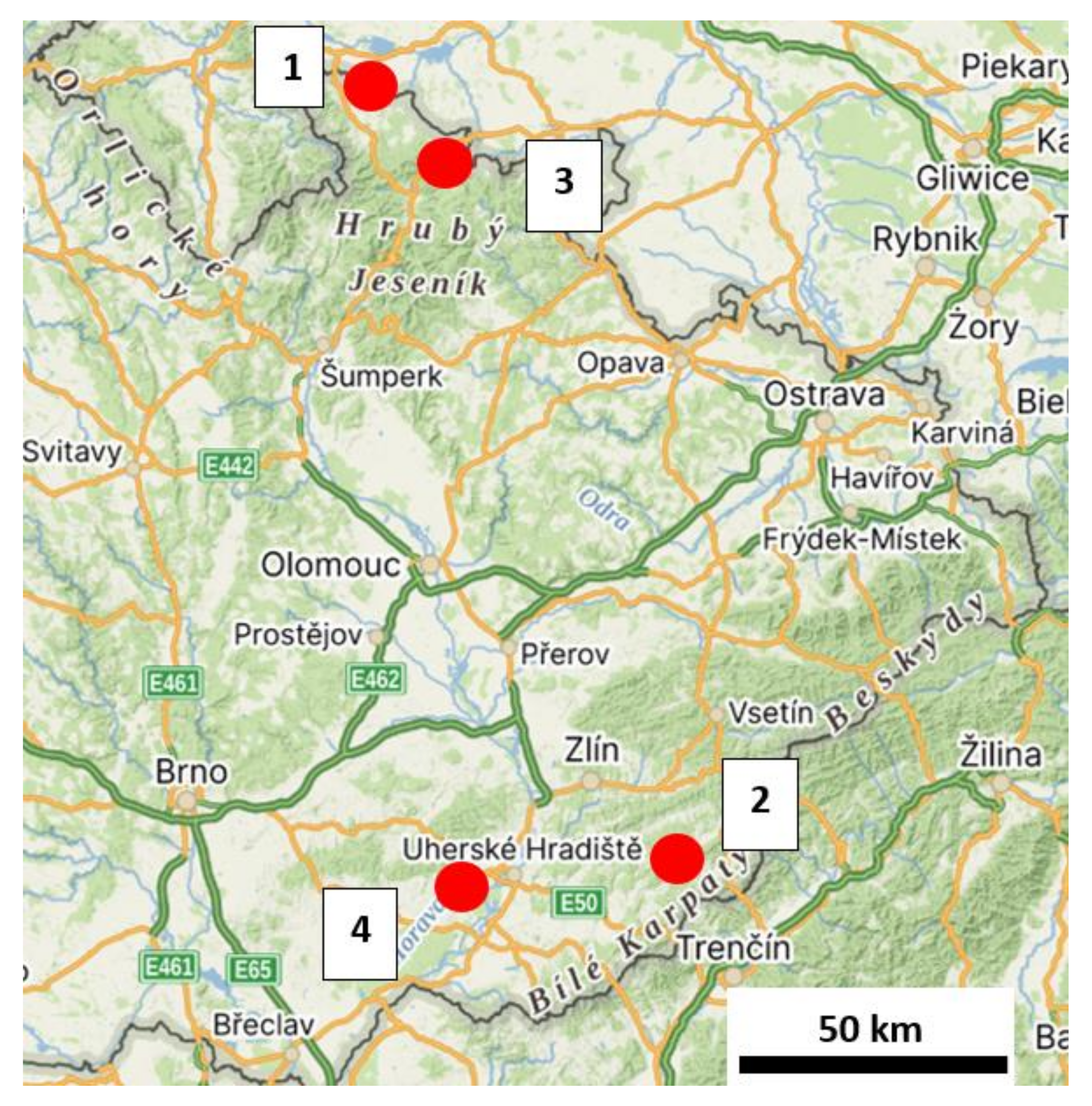
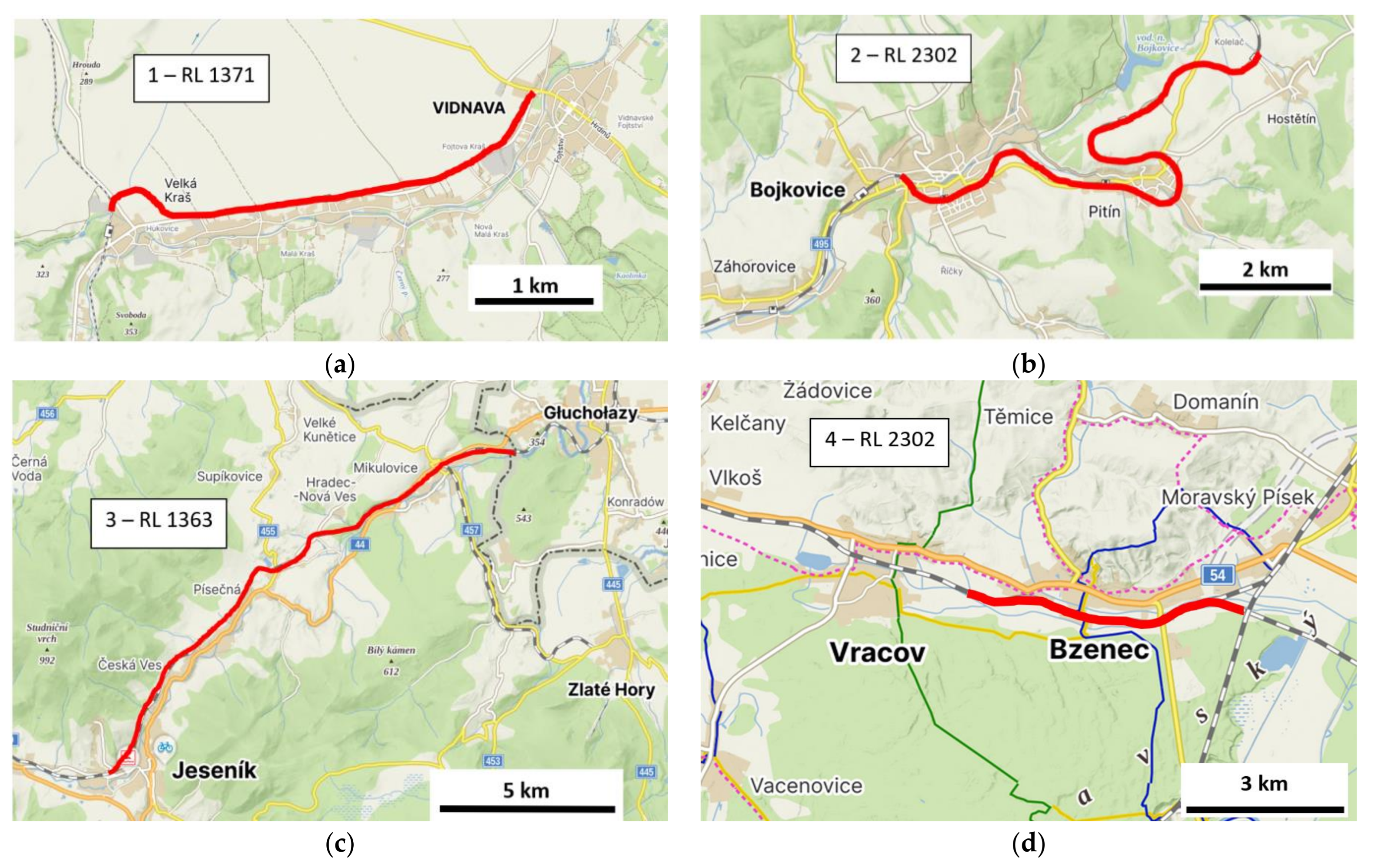
Table 1 shows the identifying name of the line section, supplemented by the names of the municipalities from which the railway line starts, the length of the section in kilometers, the number of determined points of the primary GNSS system in the section and the achieved sampling standard deviations in the horizontal plane in two perpendicular
X, Y directions, calculated from the variance of a series of repeated measurements according to the relations (1). The value of the standard deviation represents the uncertainty of a single measurement. If the primary system points are determined from three repeated measurements, a coordinate standard deviation of the mean value of better than 5 mm can be expected.
When determining the primary system points from three repeated measurements, a coordinate standard deviation of better than 5 mm can be expected.
Table 2 shows the achieved accuracy of the used geodetic Trimble R2 and Trimble R780 GNSS instruments in the form of the sample standard deviation of one measurement in the direction of the
Y and
X coordinate axes of the planar coordinate system JTSK calculated according to the procedure described in Chapter 2 under practically ideal observation conditions at the calibration base Brno-South. The signals used in the Trimble R2 and Trimble R780 instruments were GPS, GLONASS, Galileo and BeiDou, with tilt compensation disabled in the Trimble R780.
The accuracy of measurements obtained under railway operating conditions is two–three times worse than the accuracy obtained under practically ideal observation conditions at the calibration base Brno-South. The deterioration of accuracy is due to horizon obstructions, surrounding vegetation and the influence of multipath.
For short 5 min GNSS RTK observations, the entire observation interval is usually affected by multipath. By repeating the observation several times with a time interval of 3–4 h, the effect of multipath is reflected by an increase in the scatter of the partial measurement results. The mean value calculated from a series of multiply repeated measurements is closer to the conventional true value.
3.2. Using GNSS with Tilt Sensors
Today, manufacturers offer GNSS systems equipped with an IMU unit, sometimes supplemented by an electronic compass to compensate for the tilt of the rod. The purpose of this solution is to be able to measure inaccessible points where the vertical position of the rod is not possible. In addition to the uncertainty of the GNSS position, there is also the uncertainty of the tilt compensation. From the point of view of accurate measurements, it is necessary to distinguish the state of the instrument when the compensation is switched on or off. For accurate measurements, the tilt compensation should not be used as the accuracy deteriorates. Testing of two types of tilt sensors using a magnetometer and a micro-electro-mechanical system (MEMS) and an inertial measurement unit (IMU) has been published, e.g., in [
21].
Table 3 describes the result of the test of the measurements on the calibration base. Coordinates of the points were measured using the GNSS RTK method for 5 min with the tilt compensation switched off and then for 5 min with the tilt compensation switched on. The sensor was then rotated 180° in the horizontal plane, and the same procedure was repeated with the tilt compensation off and on. Six repetitions were taken using this procedure. This series of measurements was then repeated twice, each time at least 3 h apart. The total series was 18 measurements with tilt compensation off and 18 measurements with tilt compensation on.
Table 3 shows the RMS accuracy values shown on the instrument display and the RMS calculated from the variance of a series of measurements and the systematic deviation from the reference position.
Turning on the tilt compensation resulted in a deterioration of approximately 25% in the accuracy characteristics of the data displayed on the sensor display and calculated from the variance of a series of measurements, as compared to the condition in which the tilt compensation was turned off. At the same time, the accuracy data displayed on the sensor display differed from the accuracy results calculated from the variance of the measurement series (by approximately 50%).
Furthermore, possible systematic deviations in the two perpendicular directions of the coordinate axes in the horizontal plane were investigated. The systematic deviations were calculated from the reference coordinates determined from the measurements when the tilt compensation was switched off (average of the two positions). The systematic deviations when the compensation is switched on in the vertical GNSS position, with respect to the measurement uncertainties, are shown to be small and inconclusive.
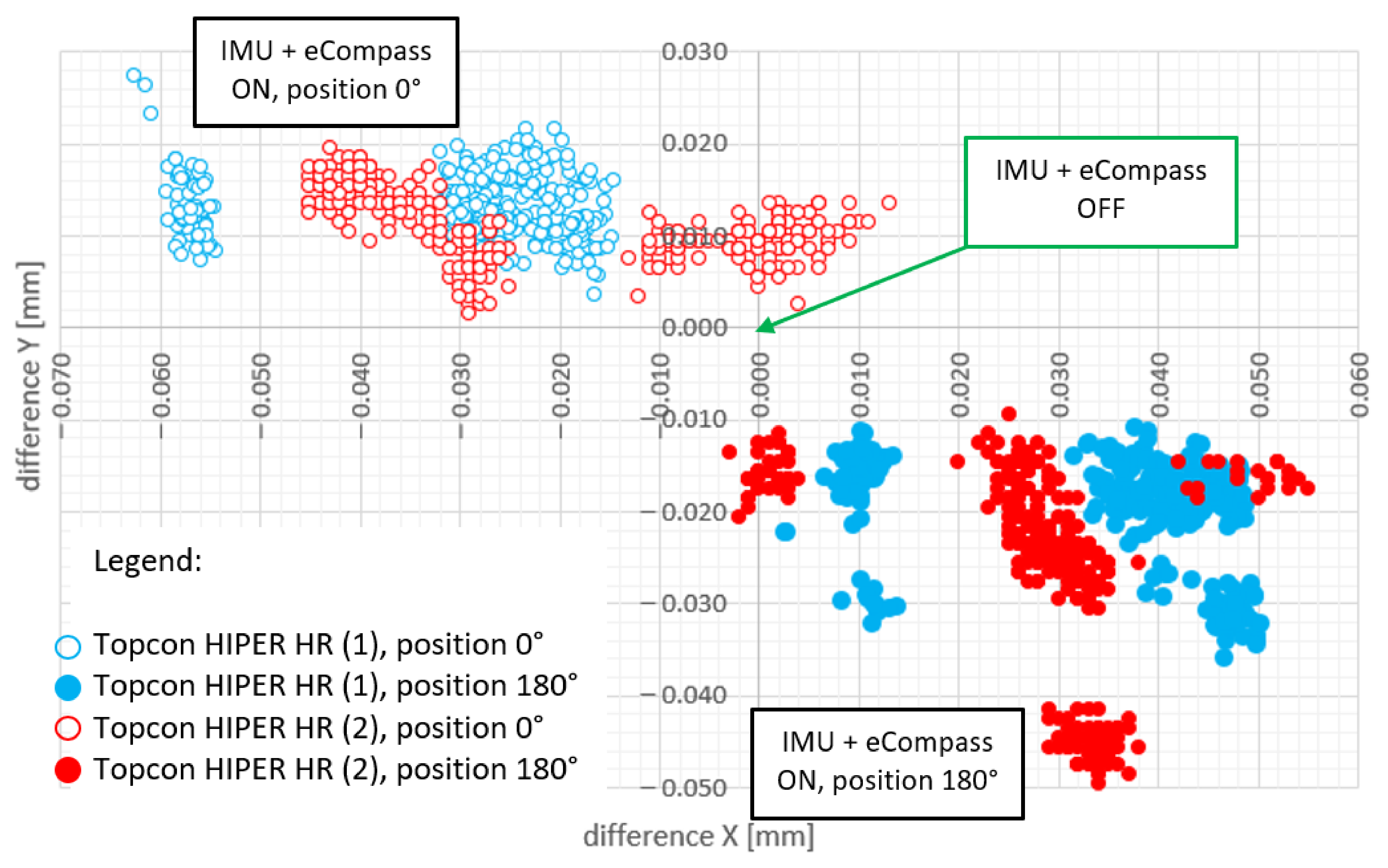
In the diploma thesis [
22], the GNSS equipment Topcon Hiper HR was tested, which is equipped with an IMU in combination with an electronic compass. With the tilt compensation switched on, the accuracy characteristics were up to three times worse than with the compensation switched off. It was also shown that a 180° rotation of the GNSS instrument in the horizontal plane with compensation switched on resulted in a systematic deviation in the horizontal component of up to 61 mm. The GNSS instrument software (HIMU v.4.6) did not automatically detect the need to initiate a targeted recalibration process, which means that there is a risk of introducing unexpected systematic errors into the precision measurement.
A pair of Topcon Hiper HR receivers were selected for the experiment. Both receivers were repeatedly measured five times for one minute (recording à 1 s) in both positions (0° and 180°) with IMU + eCompass on and off.
Figure 4 shows the positional deviations of all measurements from the mean value with the compensation switched off. The variance of the values in the 0° or 180° position is due to the repetition of the measurements at different times with independent initialization and fixation of the GNSS solution. The results show a systematic variation of several tens of millimeters between the results of the 180° measurements.
3.3. Consistency of Accuracy of Satellite and Terrestrial Measurements by the Traverse Method
The secondary system (terrestrially measured traverse) is inserted into the primary system (determined by GNSS). An important prerequisite for the integration of measurements is their metrological correctness.
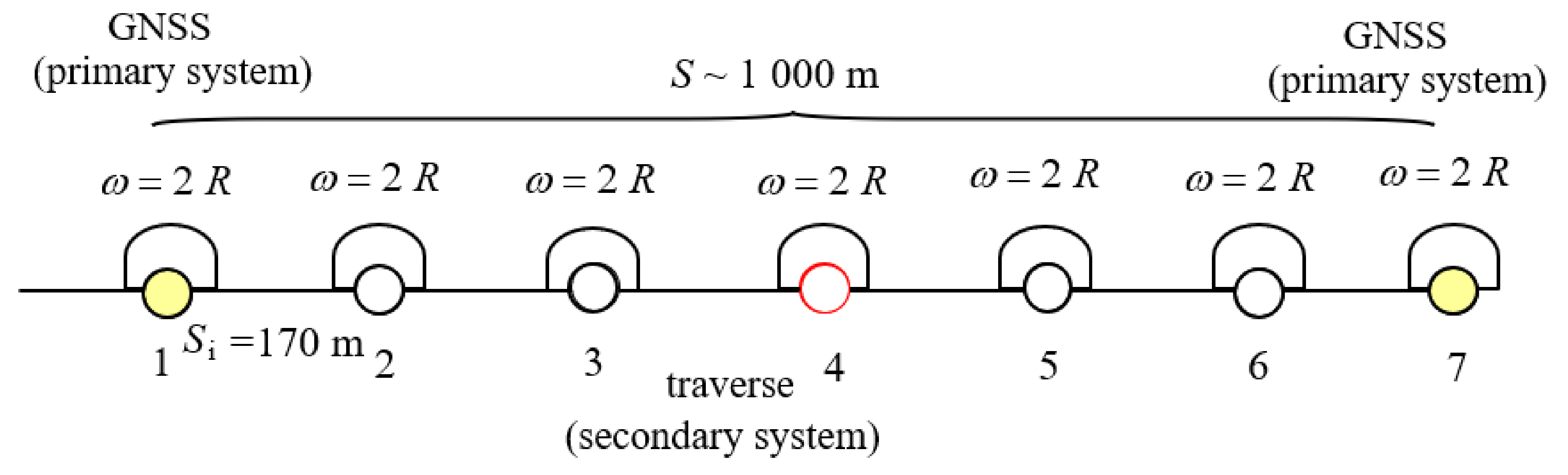
For simplicity, assume a solution model (
Figure 5) where the points of the secondary system are formed by a traverse between the points of the primary system. Assume further that the mutual distance of the points of the primary system is about
S = 1000 m, the number of vertices of the traverse is
n = 7 and the length of the sides in the traverse is about
Si = 170 m.
If we use a simplified model for a straight equilateral traverse, we can calculate the longitudinal standard deviation from Equation (2), e.g., according to [
23,
24]
and the lateral standard deviation from Equation (3)
where
is the standard deviation of the length measurement and
is the standard deviation of the angle measurement.
For example, for a total length of a unilaterally connected and unilaterally oriented traverse S = 1000 m, number of vertices n = 7, standard deviation of length measurement = 3 mm and standard deviation of angle measurement = 0.3 mgon, the end point of the traverse will be:
longitudinal standard deviation
and lateral standard deviation
The magnitude of the transverse standard deviation = 7.6 mm, or limit deviation 15.2 mm (for a confidence factor k = 2) of the traverse endpoint, is significantly higher compared to the accuracy of the GNSS determination of the point of the primary system lateral standard deviation = 5.0 mm, or a limit deviation of 10 mm (for a confidence factor of k = 2). Therefore, it is justifiable to use the higher accuracy of the GNSS determination of points of the primary system to fix (calculation invariance) the spatial position of the traverse.
Fixing the coordinates of the two endpoints of a connecting traverse between the points of the primary system results in maximum deviations in the middle of the traverse.
Longitudinal standard deviation for
n = 4,
= 3 mm (for 3 traverse legs,
S = 170 m)
and lateral standard deviation
and positional standard deviation
Table 4 shows selected parameters of the Least Squares Method (LSM) calculation of the terrestrial measured traverse (secondary system) with respect to the GNSS determined points (primary system), where the primary system points are fixed during the calculation. The LSM calculation was performed for apriori standard deviation of the angle measurement of 0.3 mgon and apriori standard deviation of the length measurement of 3 mm.
The results of the calculation of the accuracy characteristics correspond to the simplified theoretical model. The critical value of the unit standard deviation is only slightly exceeded for the second, third and fourth measured lines due to the effect of the uncertainty of the primary system points and the residual geometric inhomogeneity of the uniform transformation key. The root mean square standard deviation (RMS σp) of the secondary system points corresponds well to the homogeneity of the primary system. At the same time, the maximum standard deviation of the position σp within the calculation of the whole railway lines is also given informatively.
3.4. To Convertion to S-JTSK Using a Uniform Transformation Key
The analysis of geometric inhomogeneities of the Unified Transformation Key (UTK) (v. 2018) was performed on 18 selected lines (
Figure 6). The numerical values of geometric deformations in the form of changes in deviation per 1 km and their percentage frequencies are presented in
Table 5. DL indicates longitudinal deviation, DQ lateral, DLDQ in horizontal position. The conversion methodology between ETRF2000 and the JTSK national coordinate system is described in [
25].
Interval percentages of deformations per 1 km between the results obtained by transformation with the uniform transformation key v. 1202 (S-JTSK) and S-JTSK/05. The magnitudes of the geometric deformations of the UTK reach up to 10 mm/1 km in 90% of the horizontal coordinates and up to 20 mm/1 km in the remaining 8%.
The presence of residual inhomogeneities adversely affects metrological accuracy in terms of consistency between GNSS and terrestrial measurements.
4. Discussion
The method used for precise determination of the position of the primary system designed along the railway was tested on four different railway lines under operating conditions. Satellite instruments with GPS, GLONASS, Galileo and BeiDou signals were used, which improves the availability of a larger number of satellites, even in problematic observation conditions. The achieved accuracy is about 10–20% better than the pilot measurements with GPS+GLONASS signals published in [
12]. The availability of a larger number of satellites even under degraded operational conditions simplifies the planning of observations and enables achieving a higher reliability of results.
In the paper [
26], the authors concluded that the accuracy of PPP positioning could be improved by using BeiDou data. The time series of position components of selected EUREF Permanent Network (EPN) stations generated from sub-daily (30 min and longer) solutions was analyzed. The obtained results prove that the addition of BeiDou observations, even in the case of using an incomplete constellation, leads to visible improvements, which can be observed both in the reduction of the differences between estimated and true coordinates, as well as in the reduction of the standard deviation (SD). The improvement in accuracy due to the addition of BeiDou data is particularly noticeable for short observation sessions (in the range of 0.5–2.0 h) and in the case of a joint solution with GLONASS or Galileo observations.
The GNSS/IMU/odometer combination [
5] is suitable for indicative, rapid detection of the spatial position of the track for diagnosis and design purposes; however, it fails in longer forested sections and is not applicable during the construction or laying of new tracks.
In [
27], different non-geodetic GNSS sensors were tested, and it was confirmed that the correlations between forest cover variability and horizontal position error were significant; however, the trends were not consistent. The effect of nearby tree size on horizontal position error cannot be generalized; however, it is quite clear that there is a significant effect on horizontal position accuracy due to the presence of nearby trees. In our solution, we use geodetic GNSS sensors and quantify the degree of degradation in horizontal accuracy by comparing the accuracy calculated from the variance of a series of repeated measurements taken using the same procedure at a GNSS calibration base and under field conditions. We find a two–three times degradation in horizontal accuracy under operational railway conditions compared to ideal observation conditions at the GNSS calibration base (
Table 1 and
Table 2).
We interpret the degradation in accuracy under operational conditions as an effect due to multipath with respect to horizon obstructions and surrounding vegetation. The multipath effect affects the entire short GNSS observation time. By increasing the number of repetitions of short observations with time intervals for changing conditions (change in satellite configuration, change in multipath effect, change in atmospheric conditions, etc.) it is possible to achieve randomness of the effect of these components in the result. In [
12] the principle of repeated measurements under different conditions is used in a similar way.
The Trimble R780, for example, has Trimble EVEREST Plus to eliminate multipath, but the difference in quality is not conclusive when compared to the results obtained with the Trimble R2. For short observations, the entire observation interval is affected by multipath, and for multiple observations 3–4 h apart, the effect of multipath is reflected in increased variability in the results of a series of measurements. The mean value calculated from a series of multiply repeated measurements is closer to the conventional true value.
In the project [
20], a special Leica AT504 GG GNSS instrument designed primarily for stationary permanent stations, which is characterized by a specific construction of concentric shielding rings to reduce the influence of multipath, was used for GNSS measurements. It turned out that, in the operational conditions of the railway, the benefit of using this special instrument was not significant compared to the usual high-quality geodetic GNSS instruments.
The integration of GNSS and IMU units allows for improved positioning accuracy in difficult observation conditions and is addressed in conjunction with moving objects (vehicles, unmanned vehicles, etc.), e.g., in urban environments. For this purpose, a combined single-frequency multi-GNSS RTK/MEMS-IMU solution has been developed that, based on a Kalman filtering strategy, is well able to withstand remote measurements or low-quality observations [
28]. In our case, the GNSS/IMU is not moving during the measurement and is horizontal. The difference between the accuracy of the spatial coordinate determination computed by the instrument and the accuracy computed from the variance of a series of repeated measurements was shown. The difference in accuracy with the IMU tilt compensation unit switched on and off was also shown, with a slight deterioration in accuracy when switched on.
The results of GNSS tests with magnetometer sensors and a micro-electro-mechanical system (MEMS) and an inertial measurement unit (IMU) at vertical inclinations of 0 degrees, 15 degrees, 25 degrees, 35 degrees and 45 degrees are presented in [
21]. The IMU-based tilt sensor gave more accurate results than the MEMS sensor. Using the IMU, it was possible to achieve an accuracy of better than 4 cm in the horizontal component at a tilt of 15 degrees from vertical. Vertical accuracy was less sensitive to tilt angles when using both sensor types. Multipath was found to be more pronounced at larger tilt angles, resulting in increased horizontal errors of up to decimeters. Comparing the methods used to determine the primary system of railway lines in Germany [
14], China [
15] and Poland [
16], the construction method in the Czech Republic is mostly similar to that in Germany. In terms of accuracy, the density of GNSS points at approximately 1 km along the route followed by densification by terrestrial measurement methods seems to be optimal, where an accuracy of better than 10 mm can be achieved. The Chinese solution of a primary system of a pair of landmarks at about 4 km then leads to a slight deterioration in the accuracy of the secondary system.
5. Conclusions
On four railway sections of different length (4.5 to 16.5 km), the achieved accuracy of GNSS measurements by RTK method was analyzed according to the procedure included in the RA M20/MP007 regulation, which is used in the operating conditions of the railway in the Czech Republic. Our research has led us to the following conclusions.
It was proved that the homogeneous accuracy in coordinate standard deviation was better than σx,y = 5 mm.
The fact that GNSS instrument with GPS, GLONASS, Galileo, BeiDou signals is commonly available nowadays simplifies the preparation and planning of observations by ensuring that enough determining satellites are available under normal operating conditions of par-tially obstructed horizon.
The accuracy achieved under operating conditions was further compared with the accuracy achieved by the same procedure under ideal conditions on a calibration base. The results show that the accuracy in operational conditions is two–three times worse due to the non-ideal observation conditions, i.e., horizon obstructions, surrounding vegetation and the effect of multipath. As a result, the influence of multipath can be reduced by repeated GNSS measurements with a time interval of optimally 3–4 h, and the mean value calculated from repeated measurements is closer to the conventionally true value.
When using GNSS equipment with a tilt sensor, the accuracy of the position determination will be degraded, and therefore this mode should not be used for accurate GNSS measurements of the primary track point system. For older GNSS equipment using an IMU unit in combination with a magnetic compass, there is a risk of a systematic bias of up to several tens of millimeters, which is measured when the antenna is rotated by 180°. The use of GNSS with an IMU unit gives satisfactory results, and it is advisable to work with a 180° rotation of the instrument to improve the accuracy of the result. This is useful for geodetic points with limited access, where it is not possible to measure with levelled GNSS equipment. Changing the inclination can also influence the multipath effect to some extent.
The current uniform transformation key, in force since 2018, has residual geometric inhomogeneities (from 90% to 10 mm/km, sporadically up to 20 mm/km) that metrologically degrade the calculation results of the terrestrially measured secondary system inserted into the GNSS measured primary system.
On the whole, however, the method of determining the primary system by GNSS technology in combination with the terrestrially determined secondary system provides good homogeneity and sustainability of accuracy for the needs of construction and maintenance of railway lines, including high-speed lines. Achievement of high accuracy allows for easier analysis of inhomogeneities of the railway point field caused by their instability due to the necessity of their location in the vicinity of the operating track, and thus ensures long-term sustainability of repeatable accuracy of determination of geometric parameters regarding the center of the track.
Our research will continue in the operating conditions of electrified lines. On electrified railway lines, the geodetic points of the primary system are placed on the column footings of traction poles, which increases the risk of multipath effects.


