1. Introduction
Aerostatic bearings are considered to have the advantages of low friction, high precision, and no pollution. Aerostatic bearings are highly valued in the machining and research of fine and precision surfaces [
1]. Firstly, traditional mechanical bearings face issues such as high frictional losses, short service lives, and the need for frequent maintenance. With the increasing demand for better-performing mechanical equipment under extreme conditions like high speeds, heavy loads, and ultra-high temperatures in fields such as engineering machinery and aerospace, traditional lubrication methods are no longer sufficient. Aerostatic bearings, as a new type of support without contact or friction, can effectively address these problems experienced by traditional bearings under harsh conditions, enhancing the reliability and efficiency of mechanical systems. In addition, advances in micro- and nano-technology and computational fluid dynamics (CFD) have greatly accelerated the research of aerostatic bearings. Advancements in ultra-precision technology offer more possibilities for bearing structure design, leading to further optimization of bearing performance [
2,
3]. CFD provides an essential means for studying gas flow patterns inside bearings, aiding with improving bearing design and enhancing bearing performance [
4]. Through the application of ultra-precision technology and computational fluid dynamics, researchers can better understand the working principles of aerostatic bearings, thus driving continuous innovation and development of this technology. Additionally, research on aerostatic bearings has garnered attention and support from the international engineering community. The increasing demand in fields like aerospace, energy, etc., is setting higher requirements for mechanical equipment.
In recent years, with the increasing complexity of equipment, the precision requirements for key components have become higher and higher. Aerostatic bearings, as one of the core components of precision equipment, have attracted widespread attention. Therefore, it is necessary to conduct a more in-depth study on the design, manufacturing, and characteristics of gas static-pressure thrust bearings [
5,
6,
7,
8,
9,
10]. The throttle valve, an important component that affects the performance of aerostatic bearings, can be classified as a small-hole throttle valve, an annular throttle valve, a narrow-slot throttle valve, or a porous throttle valve [
11,
12]. Among them, the orifice throttle valve has a simple structure, convenient processing, and relatively stable overall performance, making it the focus of research for many scholars [
13].
Aerostatic bearings have garnered extensive attention from researchers worldwide. Initially, Willis [
14] introduced the concept of hydrostatic gas bearings. Subsequent studies, such as by Gao et al. [
15], leveraged computational fluid dynamics to investigate the performance of aerostatic thrust bearings with a six-hole design, focusing on how various operational parameters affect their efficacy. Li et al. [
16] employed Reynolds numbers to gauge micro-vibration levels in gas hydrostatic circular thrust bearings, with the aim of improving stability through structural optimization and Reynolds number maximization. Furthermore, Lu et al. [
17] applied the finite difference method (FDM) and the flow balance principle in Cartesian coordinates to resolve the primary equation governing multi-hole integrated orifice restrictor aerostatic bearings, noting substantial changes in load capacity and stiffness based on orifice count and size. Sahto et al., [
18] advanced the study by modeling and simulating the static properties of porous, orifice, and multi-orifice aerostatic rectangular thrust bearings, particularly examining how increased gas pressure affects load capacity and stiffness. Salem [
19] explored the effects of pad geometry and inlet conditions on the performance of externally pressurized rectangular gas bearings through experimental methods. Belforte et al. [
20] utilized laser technology for experimental studies on micro-orifice gas bearings with both circular and rectangular pads, examining the influence of micro-orifice numbers and diameters. Federico [
21] introduced inherently compensated rectangular gas bearings to the discourse, adopting a multi-objective optimization framework with genetic algorithms to delve into how pad geometry, supply pressure, and the positioning and size of supply holes impact static performance. Colombo et al. [
22] developed a parameter model for rectangular gas bearings that facilitated rapid static analysis without sacrificing accuracy and discussed the role of geometric parameters to assist bearing design researchers. They presented the analysis in a dimensionless format, aiming to enhance the model’s general applicability. Zhang et al. [
23] focused on air hydrostatic thrust bearings for ultra-precision micro-machining tools, innovating designs with single- and double-row hole structures and incorporating various pressure-equalizing grooves on the bearing surface. Utilizing computational fluid dynamics, they simulated air film behavior to assess pressure distributions, highlighting the benefits of a double-row hole configuration for these applications.
Existing research has largely focused on the characteristics of bearings, but it has not thoroughly investigated their operational stability. This study advances the field by assessing the flow field area within porous aerostatic rectangular thrust bearings, applying both analytical and finite element methods. It also includes an experimental component, allowing for a comparison of results. Through the use of comprehensive finite element software, the study evaluates key metrics such as the bearing’s capacity, gas mass flow, stability, and stiffness. The impact of various structural parameters and operational conditions on the bearing’s performance is also explored, shedding light on their significance.
2. Six-Hole Aerostatic Rectangular Thrust Bearing Model
As illustrated in
Figure 1, the dashed area represents the solid domain of the porous air static rectangular thrust bearing, while the white section corresponds to the fluid domain. To explore its operational features, a model for the porous aerostatic rectangular thrust bearing was established, featuring dimensions such as the length (
L) and width (
S) of the gas outlet, the diameter (
d) of the supply holes, their depth (
H), the gap for the gas film (denoted as
h), and the supply gas pressure (
). The configuration of the hole plate array is rectangular, with length
a and its width at half the length. The principle of operation for the bearing involves a gas supply mechanism injecting pressurized gas into the bearing through the supply hole. This gas flows between the thrust plate and the bearing seat, creating a thin film of gas that supports the load. Finally, the gas is discharged at the bearing’s edge into the surroundings, thus enabling the functionality of the gas static pressure direct thrust bearing [
24].
In order to set the structural parameters and working condition parameters of the porous gas static pressure rectangular thrust bearing, it can be seen from refs. [
25,
26,
27] that in order to avoid the air film gap being too small, resulting in slipping of the air film gap, or the air film gap being too large, resulting in the bearing capacity being too low, the gas film thickness range needs to be 8
m–20
m. Too small of a diameter of the throttle hole will increase the difficulty of processing, and too large of a throttle hole will produce gas accumulation, so the diameter of the throttle hole is selected to range from 0.2 mm to 1.0 mm. Under normal circumstances, the gas supply pressure of the aerostatic thrust bearing is between 0.2 MPa–0.6 MPa. Bearing length and width are determined based on the structural parameters of the aerostatic guide rail, and the throttle holes are uniformly distributed across the bearing. Therefore, the basic parameters of the bearing are shown in
Table 1.
3. Performance Analysis of Bearings Based on an Analytical Method
3.1. The Reynolds Equation for Gas Bearings
When designing bearings, comprehending various parameters is crucial; the parameters encompass load-carrying capacity, stiffness, flow rate, and stability [
28,
29]. Certainly, the distribution of gas pressure within the clearance of the bearing is critical to its performance. The pressure distribution equation can be derived from the equations governing gas motion, continuity, gas state, and energy [
30].
The Reynolds equation [
31] can be simplified to:
In the specified formula, p indicates the gas pressure measured in MPa, refers to the gas’s dynamic viscosity, is the density of the gas, and h points to the thickness of the film. Q is considered the correction term for flow rate. If is 1, it is at the throttle hole, and if is 0, it is at the non-throttle hole.
Setting the initial boundary conditions for pressure, the bearing throttle hole, and the bearing pressure is crucial. Specifically, the initial pressure boundary condition is outlined as follows:
In the formula, represents the bearing outlet pressure, while denotes the gas supply pressure at the throttle orifice.
3.2. Computational Solution
Using the finite difference approach to calculate Equation (
1) provides the pressure within the gas film at a specific node:
In applying the successive over-relaxation (SOR) technique to address this equation, the iteration ceases under the following condition:
The equation employed for determining the load capability of a bearing is:
Upon calculating the load capacity corresponding to a certain air film thickness
h, one can ascertain the air film’s stiffness through application of Equation (
7).
In the aforementioned equation, K denotes the static stiffness, W signifies the static load capacity, and h conveys the incremental change in air film thickness.
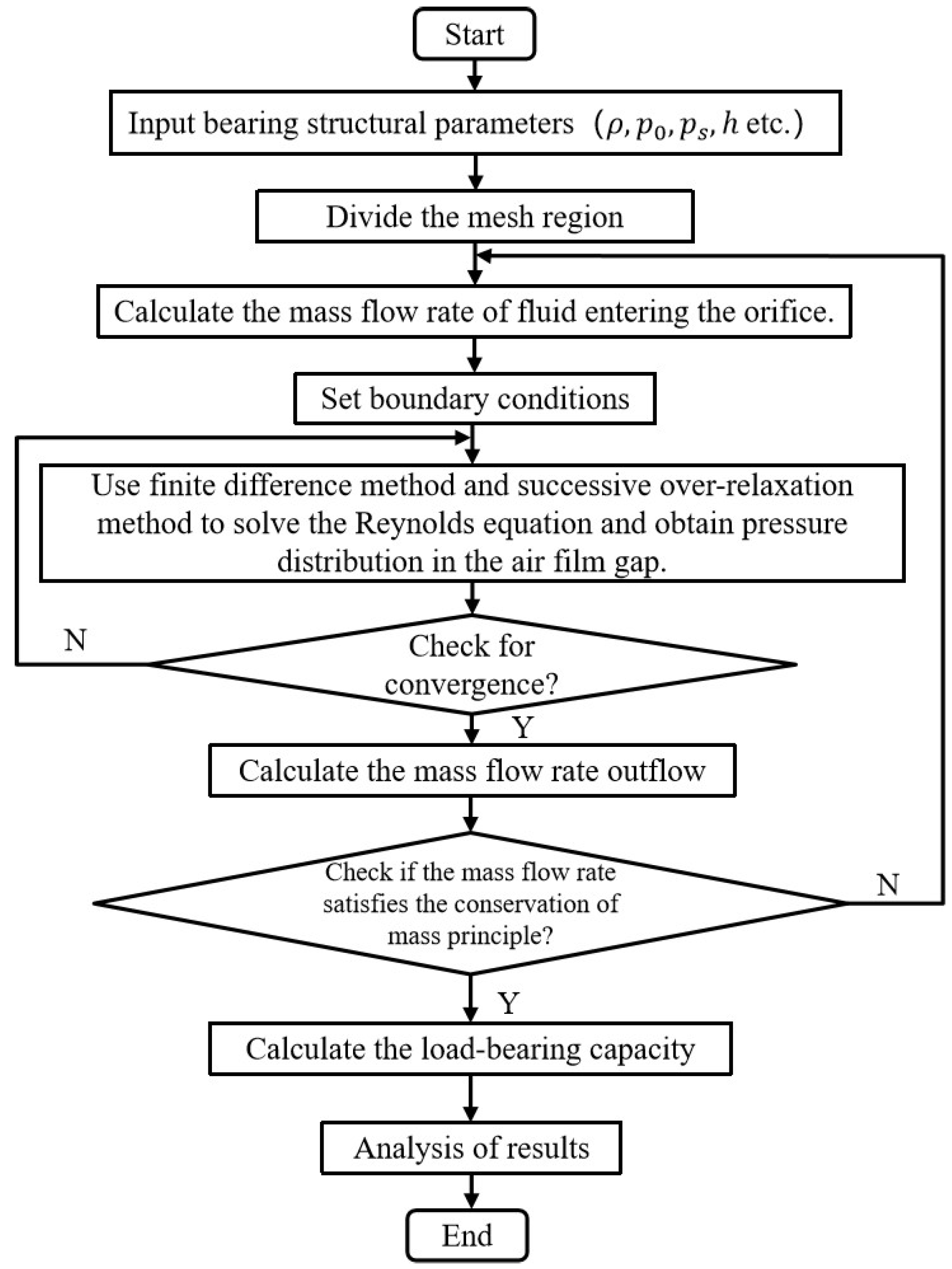
The procedure for obtaining a numerical solution, as illustrated in
Figure 2, starts with the determination of specific parameters for the bearing model and proceeds with grid generation within the scope of the model. The pressures at the bearing’s inlet and outlet for the supply air are set, allowing for the calculation of mass flow rate at the entrance of the supply port. Initial pressure inputs are integrated into the discrete Reynolds equation for analysis. An iterative process is employed to refine the values within the pressure field; once the variance between two successive iterations complies with the convergence threshold, the sequence transitions to the subsequent phase. If convergence has not been achieved, the iteration cycle persists. The mass flow rate at the discharge of the bearing is then calculated. Upon achieving convergence, the established pressure distribution is treated as the conclusive outcome. This pressure profile then serves as the basis for subsequent computation of the load-carrying capacity of the bearing.
4. Characteristic Analysis Based on the Finite Element Method
The performance [
32] of a gas-lubricated bearing is governed by its airflow dynamics. For evaluating the airflow dynamics of a gas-lubricated bearing, the flow field area of a six-hole gas-lubricated rectangular thrust bearing is defined. The boundaries delineating the entirety of the flow field, encompassing the upper bearing surface, lower bearing surface, orifice wall, pressure inlet, and pressure outlet, are depicted in
Figure 3.
4.1. Mesh Generation
The precision of calculation and results analysis is directly affected by the mesh quality [
33]. Due to the extremely small working film clearance in gas-lubricated bearings, it is difficult to automatically generate a mesh during the partitioning process. To ensure more accurate computational results, structured mesh partitioning is required, with local refinement at the junction between the orifice and the upper bearing surface.
Figure 4 displays the mesh partitioning outcomes for the internal flow field region of the bearing.
4.2. Basic Assumptions and Boundary Conditions
Assume that the gas is ideal air at room temperature (300 K) with a density of 1.225 and a viscosity of 1.78910 × . It is assumed that the bearing surface is smooth, the effects of surface texture are ignored, and it is considered that the material stays unaltered in form.
The inlet of the supply orifice is identified as the pressure entry point, defined by the given supply gas pressure . The exit is established as a pressure discharge point, matching the normal atmospheric pressure = 0.101 MPa. A no-slip boundary condition is imposed on the wall surfaces.
The model was solved using the finite volume method (FVM), with the selection of a second-order upwind discretization scheme to maintain solution accuracy. The main physical parameters examined in the following analysis include the distribution of gas film pressure, the mass flow rate, and the velocity profile. Therefore, a computational algorithm utilizing the SIMPLE pressure correction method was employed for the calculations.
4.3. Mesh Independence Analysis
A grid convergence test was conducted on the model to mitigate the impact of the number of structured grids on the simulation results. The computational outcomes are presented in
Table 2, wherein calculations were carried out using four sets of different grid numbers. The calculated values of the bearing capacity
W, air consumption
Q, and maximum air velocity
V differ by no more than 5%. Considering that an excessive number of grids will increase the computational workload, a grid number of 2,849,645 was chosen for subsequent experiments.
4.4. Simulation Results
The convergence criterion is defined such that the residual of each physical quantity is deemed to have converged when it is less than
. Additionally, the calculation is considered valid when the relative error of mass flow at the inlet and outlet is less than
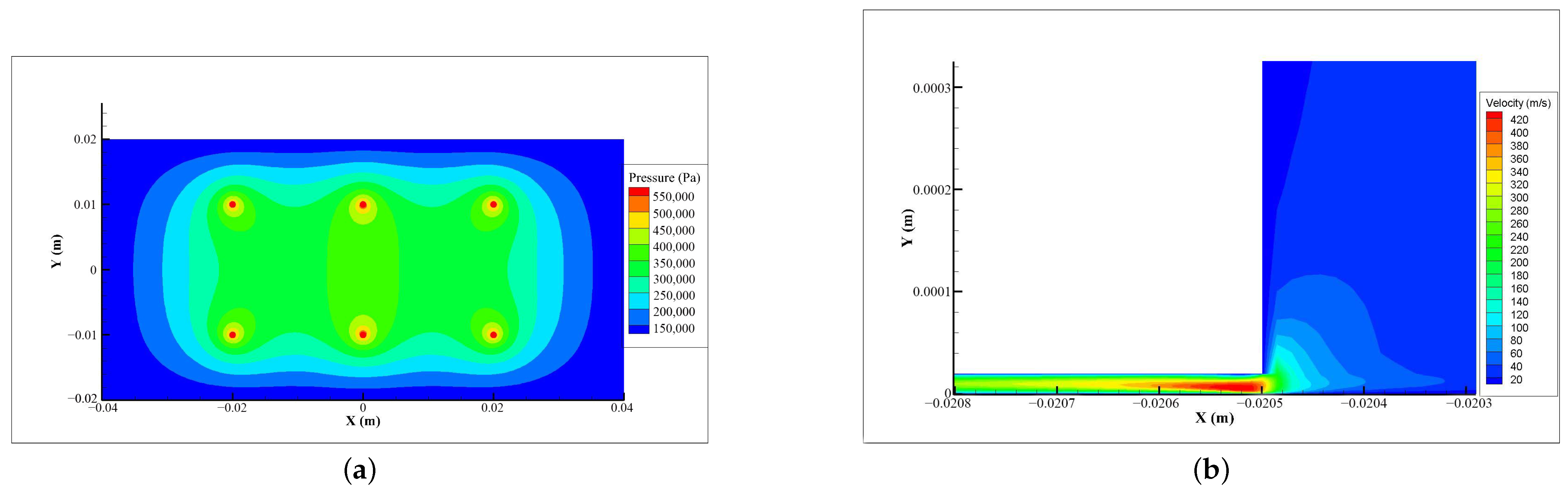
. The top-view pressure contour displayed in
Figure 5a represents an array of rectangular throttle orifices characterized by 40 mm length, a throttle aperture with a 1 mm diameter, a gas film gap measuring 20
m, an input air pressure of 0.6 MPa, and an exhaust pressure set at 0.101 MPa. By observing the velocity distribution in the flow field region profile, the maximum velocity is obtained and the calculation results are derived. The gas flow velocity distribution within the gas film gap is analyzed, yielding contour maps of both pressure and velocity for aerostatic rectangular thrust bearings. Indeed, pressure and velocity contour maps provide a visually intuitive means to observe changes in pressure and velocity across the gas film. They offer valuable insights into the flow dynamics in aerostatic rectangular thrust bearings, enabling direct observation of flow changes within the system. The highest velocity, 466.659 m/s, occurs where the gas supply port meets the gap in the gas film.
5. Results and Analysis
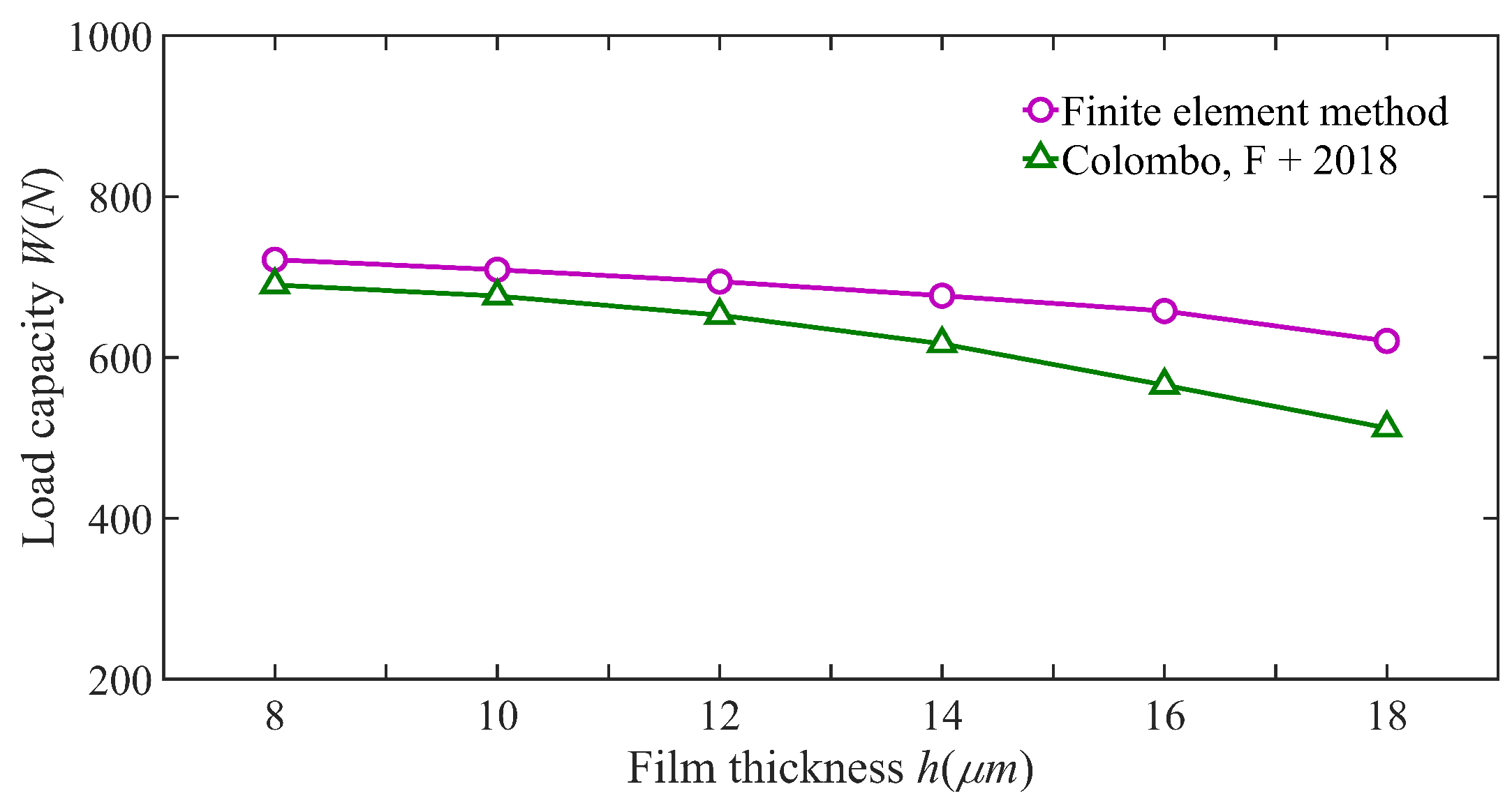
The fidelity of the finite element method was corroborated through comparison with the experimental findings presented in
Figure 6 from the referenced study [
25]. In reference [
25], the bearing had a length of 75 mm, a width of 30 mm, eight supply orifices with depths of 2 mm, and a diameter of 0.4 mm; the supply gas pressure was 0.4 MPa. The relative error between the simulation data obtained in this study and the experimental data from this paper is within 10%, indicating the reliability of the proposed method. The finite element results closely align with the experimental findings from the literature, albeit with some inherent error. The sources of error encompass the assumption of ideal laminar flow in simulations, whereas practical applications may involve turbulent flow and other influential factors.
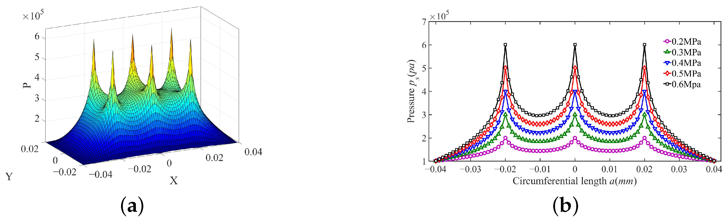
The three-dimensional pressure contour surface of a rectangular throttle orifice array with a diameter of 0.2 mm, a gas film thickness of 20
m, a length
a of 40 mm, and with a supply gas pressure of 0.6 MPa was calculated and is illustrated in
Figure 7a.
Figure 7b shows the transverse pressure distribution across the flow direction at differing gas supply pressures, with
spanning from 0.2 to 0.6 MPa. The diagram clearly indicates that as the supply gas pressure increases, the pressure distribution escalates, highlighting a pressure drop phenomenon.
To examine the effects of diverse structural parameters and operational factors on the load capacity, mass flow properties, stability, and stiffness of porous aerostatic bearings, we analyzed changes in these four attributes under varied operating conditions. Variables included gas pressure, orifice diameter, gas film thickness, and the distribution of orifices.
5.1. Factors Affecting the Bearing’s Load Capacity
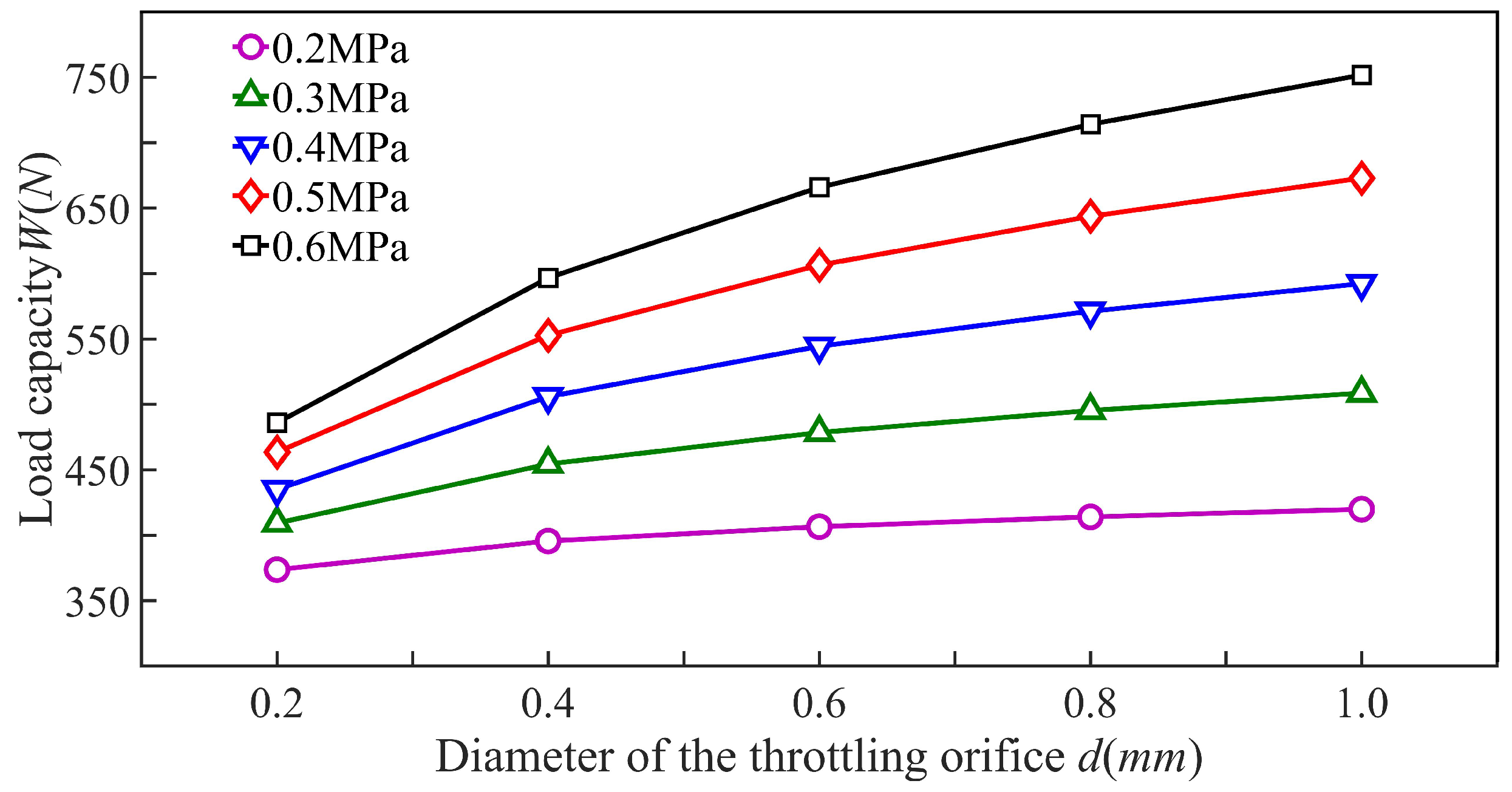
Under different gas supply pressures,
Figure 8 illustrates the trend of bearing capacity variation with the length of the rectangular orifice plate array
a fixed at 40 mm and the gas film thickness maintained at 20
m across a range of throttle orifice diameters. With supply gas pressure held constant, there is an observable increase in bearing capacity as the diameter of the throttle orifices enlarges.
Figure 9 demonstrates how bearing capacity varies with gas film thickness under varying gas supply pressures given a constant rectangular throttle hole array length of 4 mm and a supply hole diameter of 0.2 mm. When the gas supply pressure remains unchanged, a reduction in gas film thickness leads to enhancement of the bearing capacity.
Figure 10 showcases the fluctuations in bearing capacity under divergent supply pressures and assorted distributions of throttle holes with the supply hole diameter established at 0.2 mm and the gas film thickness set at 20
m. With a constant gas supply pressure, the bearing capacity experiences an initial rise followed by a decline as the
x parameter increases, peaking at
24 mm.
5.2. Factors Influencing the Air Consumption of the Bearing
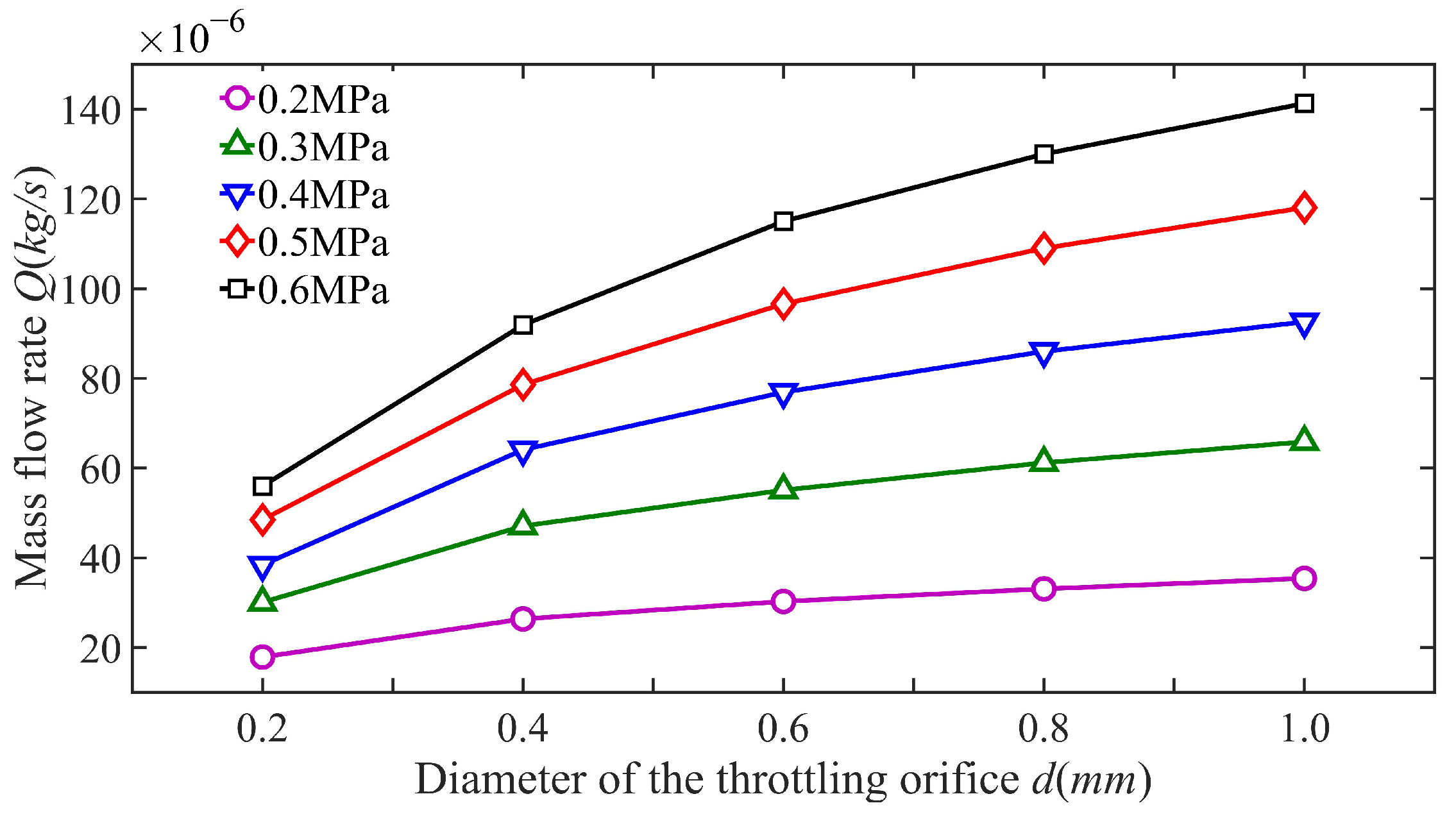
Figure 11 depicts the variations in gas usage across various orifice diameters under different gas supply pressures considering a rectangular orifice array length of 40 mm and a gas film thickness of 20
m. Holding the supply pressure steady, the bearing’s air consumption escalates with an increase in throttle hole diameter.
The changes in air consumption associated with varying gas film thicknesses at several gas supply pressures are illustrated in
Figure 12, where the length
a of the rectangular throttle orifice array is kept at 40 mm and the diameter of the gas supply hole is 0.2 mm. With a constant gas supply pressure, an increase in the thickness of the gas film leads to a rise in the bearing’s air consumption.
Variations in air consumption due to different arrangements of throttle holes at a range of gas supply pressures are demonstrated in the data presented in
Figure 13. This illustration confirms that with a uniform gas supply pressure condition, the dimension of the gas supply hole fixed at 0.2 mm, and the gas film thickness set to 20
m, there is an observed increase in the air consumption for the bearing corresponding to an enlargement of the length
a.
5.3. Factors Affecting Bearing Stability
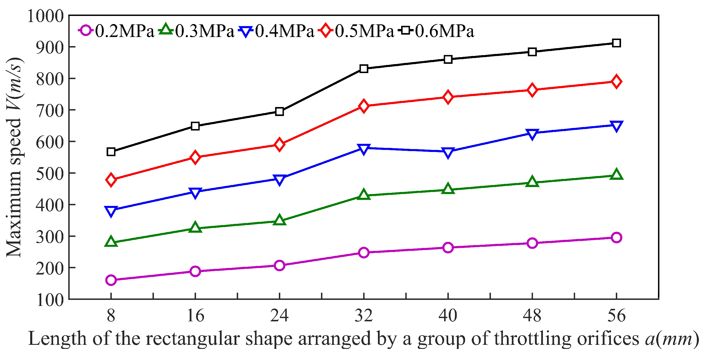
The trend of maximum airflow velocity with changes in the orifice diameter under various air supply pressures is depicted in
Figure 14 for a fixed length
a of the rectangular orifice array at 40 mm and an air film thickness of 20
m. With a fixed gas supply pressure, it is observed that an increase in the throttle hole diameter results in a reduction in maximum air velocity in the gas film gap, suggesting enhanced stability of the bearing.
The relationship between maximum airflow velocity and air film thickness variations for differing supply air pressures is outlined, with the specifics provided including a 40 mm length for the rectangular orifice array and a 0.2 mm diameter for the orifice, as displayed in the data of
Figure 15. Holding the supply gas pressure steady shows that a reduction in the thickness of the gas film is directly associated with a decrease in the peak airflow velocity within the gas film gap, which serves as an indication of the bearing’s stability.
As demonstrated in the data from
Figure 16, variations in orifice distribution under varied supply air pressures affect the maximum air velocity when considering a constant supply orifice diameter of 0.2 mm and an air film thickness of 20
m. Keeping the supply gas pressure unchanged, it is noted that an increase in the orifice spacing, referred to as
a, leads to a rise in the maximum airflow velocity across the air film clearance. This pattern suggests deterioration in the stability of the bearing.
5.4. Factors Influencing Bearing Stiffness
The relationship between the variation in bearing stiffness and gas film thickness across different throttle hole diameters is depicted in the data shown for a configuration for which the length of the rectangular orifice array
a measures 40 mm and with a gas supply pressure of 0.5 Mpa, as per
Figure 17. For throttle hole diameters ranging from 0.4 mm to 1 mm, there is an observed increment in stiffness corresponding to the increase in gas film thickness. Conversely, when the throttle hole diameter is set to 0.2 mm, the stiffness demonstrates growth followed by decline as the gas film thickness increases, peaking at a gas film thickness of 14
m. The reduced throttle hole diameter correlates with a marked rise in bearing stiffness, showcasing that micro-porous bearings are more stable. In the context of practical bearing designs, aiming for a gas film thickness in the vicinity of 14
m is advisable to secure higher stiffness and thus achieve enhanced stability in the bearings.
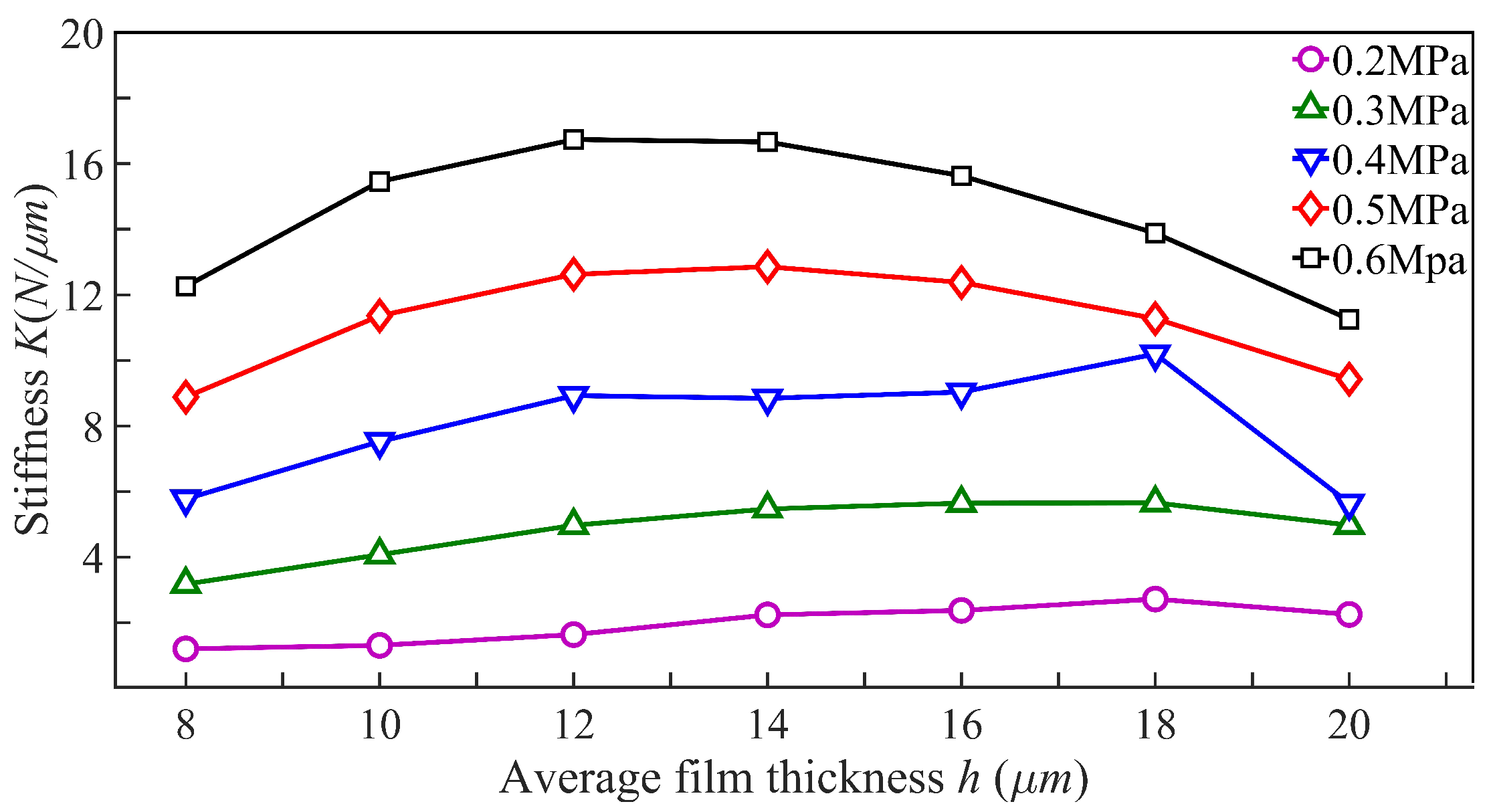
The dependence of bearing stiffness on air film thickness across varying supply air pressures is illustrated in
Figure 18. This configuration employs a rectangular orifice array with a length of 40 mm and an orifice diameter of 0.2 mm. An initial rise in stiffness is observed as the air film gap enlarges, followed by a subsequent decline, with each condition reaching a peak stiffness at approximately 14
m. Furthermore, it is noted that escalation of supply air pressure contributes to augmentation of the stiffness of the bearing.
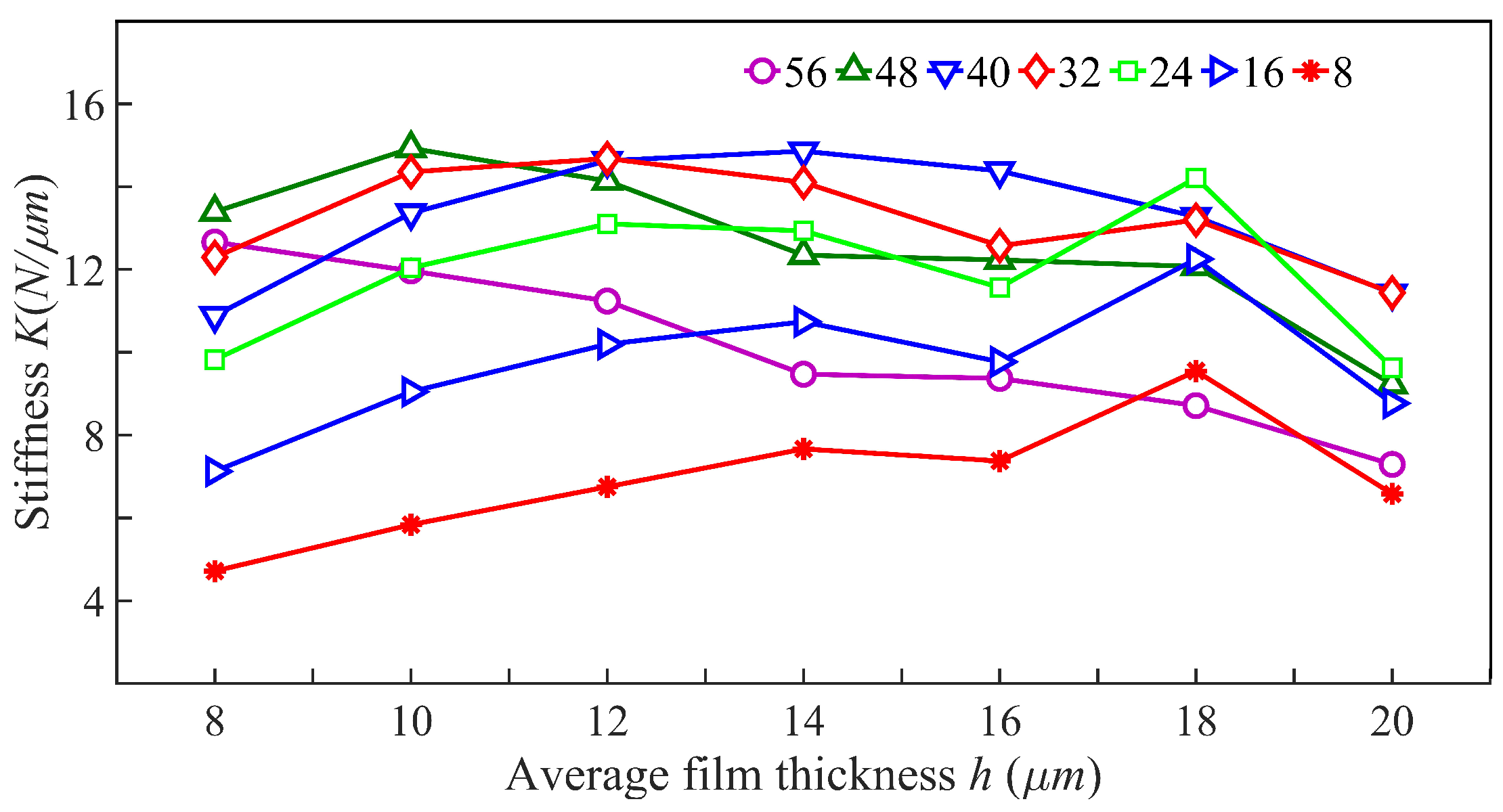
Variations in bearing stiffness in relation to air film thickness under assorted orifice arrangements are delineated in
Figure 19. This is for orifices with a diameter of 0.2 mm and subjected to a supply air pressure of 0.5 Mpa. The data suggest that optimal stiffness of the bearing is achieved with a rectangular orifice array of 40 mm in length, where maximum stiffness is attained at an air film thickness of 14
m.
6. Experimental Research
To validate the precision and dependability of the finite element and analytical techniques proposed in this research for modeling a porous aerostatic rectangular thrust bearing, an experimental investigation was conducted. The purpose of this investigation was to identify the optimal structural configuration and to select a suitable manufacturing technique for producing porous gas static-pressure rectangular thrust bearings that adhere to experimental standards. The bearing’s static performance was assessed through rigorous experimentation, and the outcomes were evaluated against the simulations. Consistency between the bearing capacities identified through finite element and analytical methodologies with those observed in experimental settings under identical operational conditions would confirm the effectiveness of the methods introduced in this study.
The apparatus for measuring the carrying capacity of aerostatic thrust bearings is depicted in
Figure 20. An air pump delivers adjustable and consistent high-pressure air to both the bearing and the loading cylinder, allowing the bearing’s working surface to hover between the platforms. The rod of the loading cylinder is linked to a tension pressure sensor, ensuring that steady force is exerted on the bearing, which is quantified by this sensor. Concurrently, the gap of the bearing’s gas film is determined using an inductance micrometer.
Due to the many factors that can affect the measurement results, including auxiliary part machining errors, sensor installation errors, environmental vibrations, and fluctuations in the gas supply, each parameter was measured five times, and the value of each parameter was compared with the theoretical analysis results.
Load capacity experiments were conducted on a rectangular bearing characterized by 0.2 mm diameter throttle holes and a length of 40 mm. Four distinct supply pressures, 0.3, 0.4, 0.5, and 0.6 Mpa, served as the baseline for assessing variations in load-bearing ability relative to the thickness of the gas film. Experimental findings were subsequently juxtaposed with outcomes derived from finite element and analytical predictive techniques, all of which are documented in the graph in
Figure 21.
The results of the study revealed a correlation between theoretical analysis and experimental data. It was observed that under varying pressures, the outcomes from the experimental groups aligned with trends predicted by both finite element methods and analytical approaches. Analytical approaches demonstrated closer congruence to finite element methods with minimal discrepancies. The differences observed could be attributed to the adoption of a turbulence model in finite element analysis, predicated on the vortex viscosity assumption. Conversely, discrepancies with experimental observations were due to simplifications made in the model by both finite element and analytical methods, leading to certain inaccuracies. Across the four sets of supply pressures, it was noticed that discrepancies were minimal at smaller gaps between experimental data, finite element outcomes, and analytical results. However, as the thickness of the gas film increased, the divergence between experimental measurements and predictions from finite element and analytical methods gradually widened. This variance could likely stem from experimental procedures that obtained gas film thickness by altering load conditions in contrast to the approaches of finite element and analytical methods. The largest discrepancies under the four supply pressures, both for finite element and experimental methods, were noted for the 18 m gap.
Upon cross-validating the outcomes derived from the finite element methodology with those from analytical techniques and empirical testing, we established that the advanced finite element and analytical strategies, along with their numerical findings, uphold precision. Thus, this substantiates the accuracy and dependability of finite element and analytical modeling for porous gas static-pressure rectangular thrust bearings.
7. Conclusions
In this study, the flow dynamics within a porous aerostatic rectangular thrust bearing are examined through both analytical and finite element analyses. The reliability of the finite element approach and analytical outcomes is further affirmed by experimental validation. The analytical technique specifically facilitates the formulation of a procedure to calculate the bearing’s load-carrying capacity, which is subsequently corroborated against the findings from the finite element analysis. The employment of the finite element method leads to the following deductions:
(1) The arrangement of throttle orifices greatly affects the performance of the bearings. As the length a of the rectangular array of throttle orifices increases, both the air consumption and the maximum velocity within the gas film gap increase. Consequently, the bearing load capacity initially rises and then declines. The bearing load capacity reaches its peak when the length a of the throttle orifice array is 24 mm. However, when a is 40 mm, the bearing stiffness reaches its maximum.
(2) When the film thickness ranges between 8 and 20 m, smaller thickness leads to a higher load-carrying capacity. Decreasing the film thickness during gas bearing operation also reduces gas consumption and the maximum airflow velocity within the film gap, thereby enhancing the bearing’s stability. Stiffness increases with thicker films, peaking at a thickness of 14 m. However, employing the minimum film thickness during operation may heighten manufacturing and installation complexities, necessitating comprehensive consideration of processing conditions and load demands when determining this value.
(3) A greater throttle hole diameter yields a greater bearing load-carrying capacity. Nonetheless, it also induces increased gas consumption and a lowered maximum airflow velocity within the film gap, consequently reducing stiffness.
(4) As the supply pressure of the gas is heightened, there is an observed enhancement in the load-bearing capability, gas usage, and stiffness of the bearing. Nevertheless, this increase in supply gas pressure equally intensifies the peak velocity of the airflow across the film gap, which in turn can undermine the stability of the bearing.
(5) After an exhaustive analysis of the model’s structural parameters, the following design parameters were selected: a bearing throttle hole diameter of 0.2 mm, a gas film thickness of 8 m, a rectangular array length of throttle holes of 40 mm, and a gas supply pressure of 0.5 Mpa.
This investigation into the characteristics of porous gas static-pressure rectangular thrust bearings using both CFD and analytical methods holds significant engineering importance. It offers a more precise comprehension of these bearings’ characteristics, encompassing parameters like load capacity, stiffness, and damping. Consequently, it establishes a scientific foundation for bearing design and optimization, aiming at achieving efficient and reliable operation. Through the diagnosis and analysis of operational issues, the establishment of a health management system becomes feasible, enabling real-time monitoring and prediction of long-term operational states. This facilitates the early detection of potential problems and the implementation of corrective measures, thereby aiding with achieving high-precision processing and long-term stability. To sum up, the investigation into the static characteristics of porous gas static-pressure rectangular thrust bearings through CFD and analytical approaches is expected to have broad engineering applications going forward, potentially fueling technological progress and innovation in associated domains.
In addition, the intelligentization and real-time monitoring of gas static-pressure thrust bearings is an important area of research. In the future, we will leverage existing data to implement predictive and intelligent adjustment of gas static-pressure thrust bearings under different operating conditions using machine learning algorithms and adaptive control strategies. In doing this, we aim to explore the durability and stability of bearings to maintain optimal bearing performance.


