Numerical Simulation on the Leakage-Induced Collapse of Segmental Tunnels
Abstract
:1. Introduction
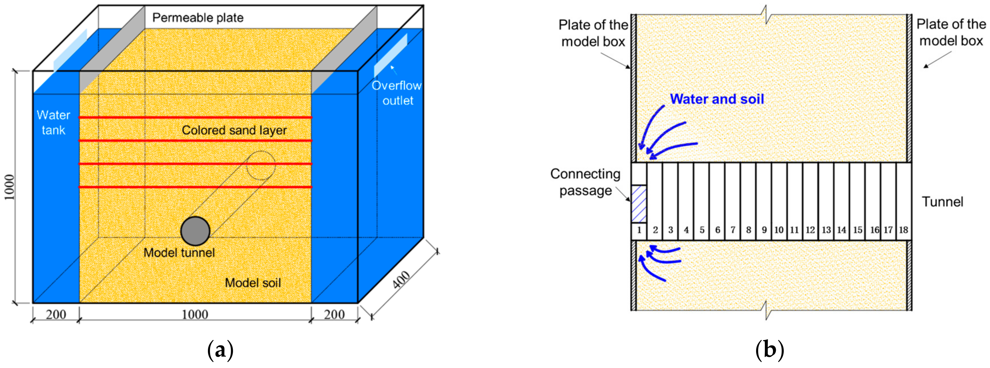
2. Model Tests
2.1. Test Design
2.2. Test Results
- (1)
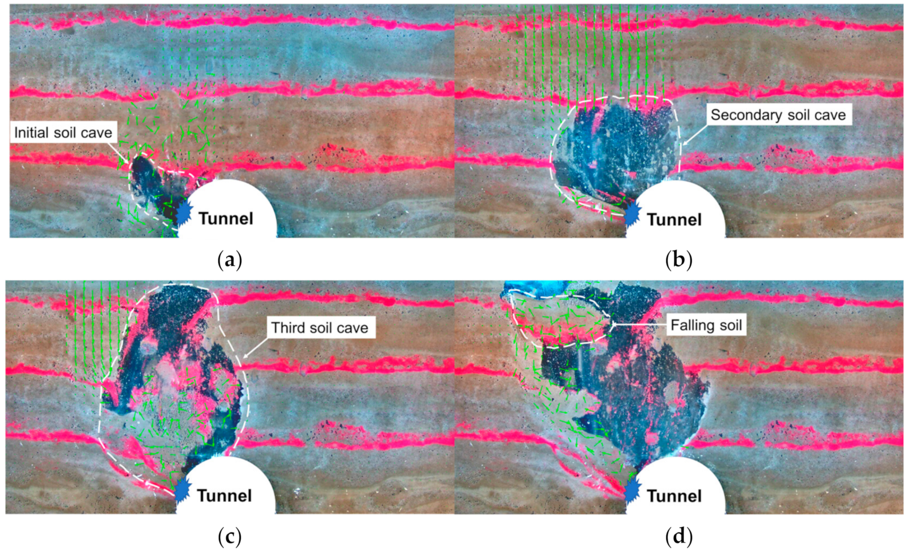
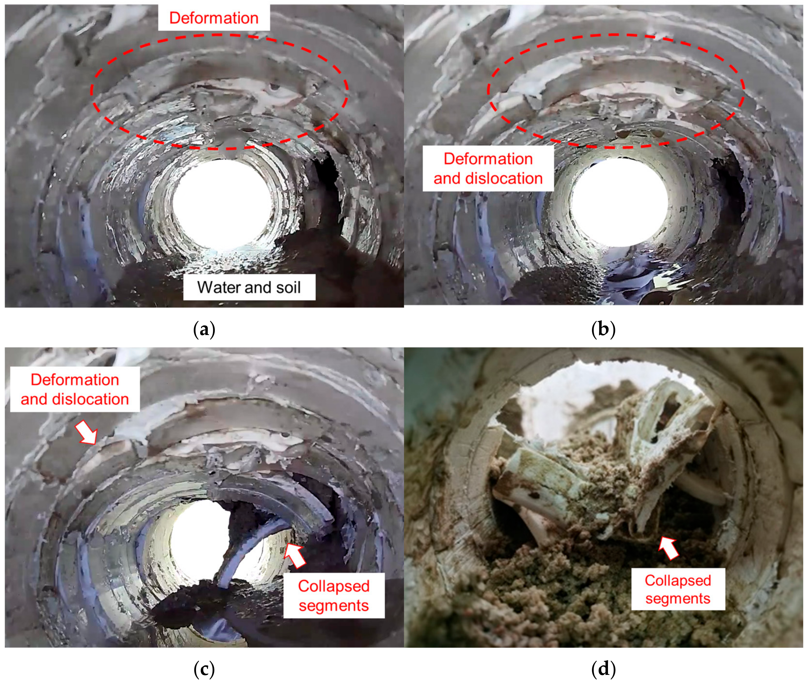
- Stage 1: After the start of water and soil rushing from the waist to the interior of the tunnel, a visible soil cave appeared on the exterior of the tunnel, and the displacement of the soil was mainly concentrated in the interior of the soil cave. The initial soil cave was temporarily stabilized, as shown in Figure 3a. At the same time, the top of the tunnel slowly deformed inward, as shown in Figure 4a.
- (2)
- Stage 2: The initial soil cave destabilized, soil erosion developed again, and the erosion area rapidly developed upward. Subsequently, a secondary soil cave formed and temporarily stabilized again, as shown in Figure 3b. For the tunnel, it was observed that the top of the tunnel showed large deformations and dislocation, as shown in Figure 4b.
- (3)
- Stage 3: After a brief period of stabilization, the secondary soil cave destabilized again and the erosion area developed upward, followed by the formation of a third soil cave. The third soil cave again entered the temporary stabilization state, as shown in Figure 3c. At the end of this stage, the top of the tunnel was impacted by falling soil, and several segments collapsed, as shown in Figure 4c.
- (4)
3. Numerical Model
3.1. Soil Model
3.1.1. Description of the Coupled Fluid–Solid Model
3.1.2. Numerical Model Based on the Tests
3.2. Numerical Tunnel Model
3.3. Model Validation
4. Tunnel Collapse Process Analysis
4.1. Strata Response
4.1.1. Seepage Erosion
- (1)
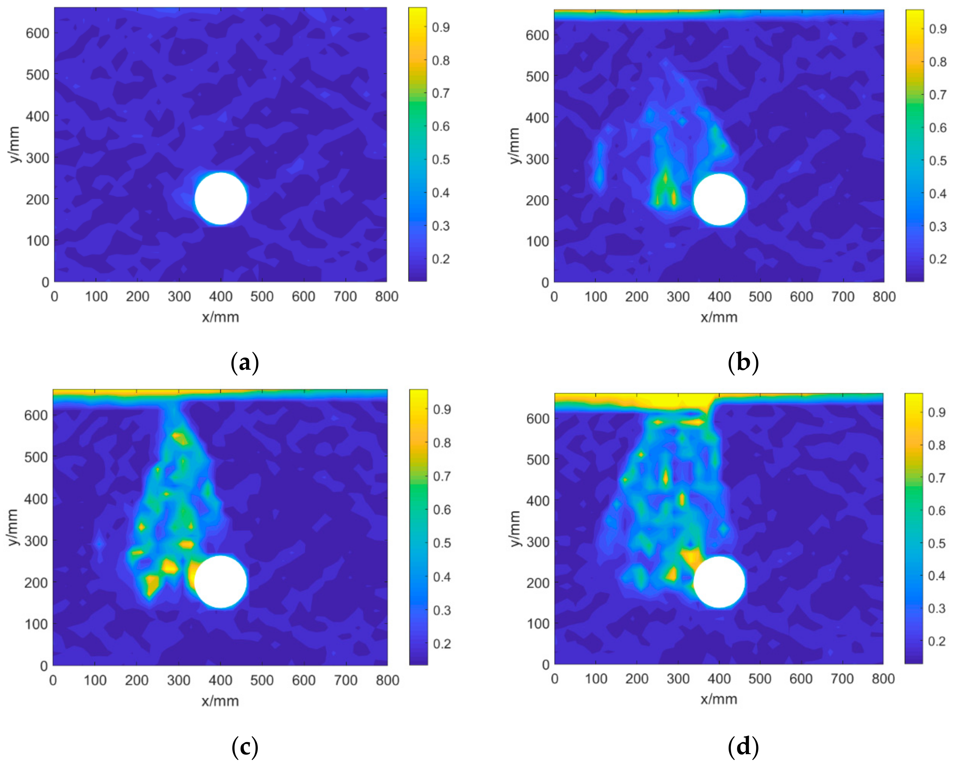
- After the tunnel leakage started, the porosity near the leakage point increased rapidly, which led to an increase in the permeability coefficient near the leakage point, and the seepage rate increased, further accelerating the erosion process, as shown in Figure 9a.
- (2)
- After the formation of the soil caves, the porosity inside the cave increased rapidly due to the loss of particles, as shown in Figure 9b,c.
- (3)
- When the strata surface subsidence occurred, a region of sharp increase in porosity was formed from the surface to the leakage point, as shown in Figure 9d.
4.1.2. Soil Arching Effect
- (1)
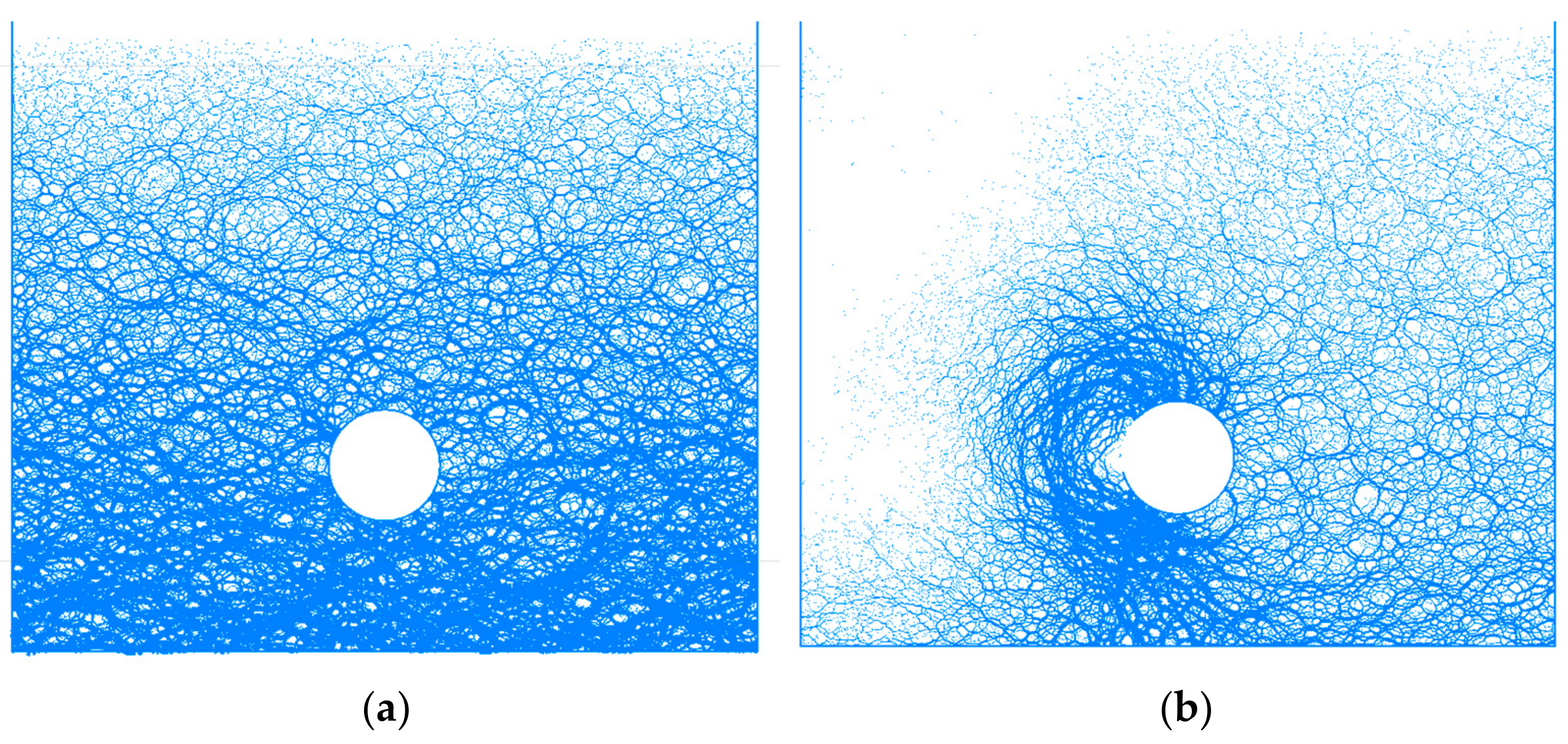
- Before the start of leakage, the distribution of the contact force showed a trend of large contact force at the bottom and smaller contact force as it went upward, as shown in Figure 10a. The reason is that the soil stress at the bottom is larger due to gravity.
- (2)
- After the leakage, a visible soil arch first appeared near the leakage point, and the soil arch feet fell at the top as well as the bottom of the tunnel, which generated an initial soil cave in the external strata, as shown in Figure 10b.
- (3)
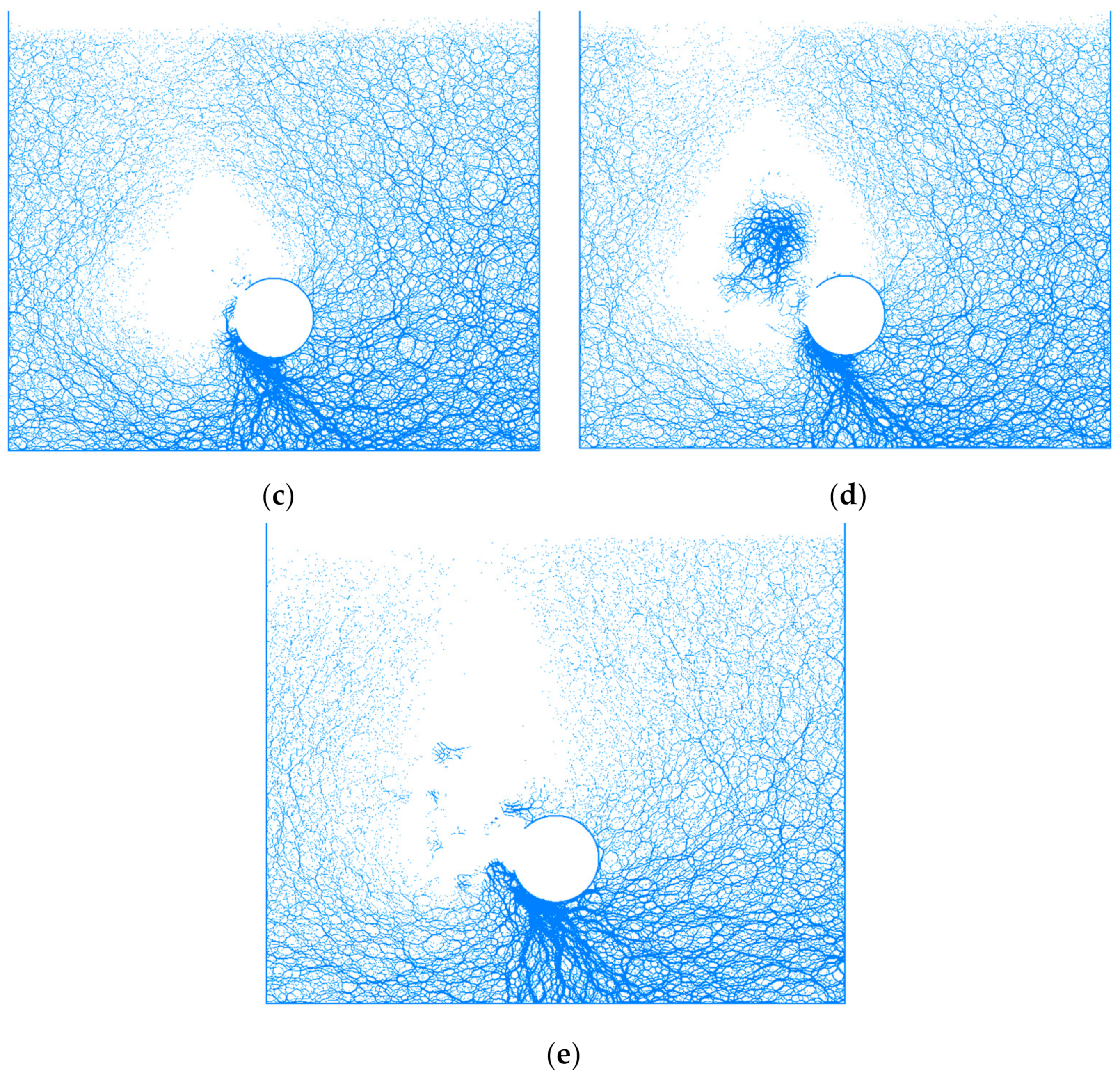
- The initial soil arch was destabilized with the development of seepage erosion, and then a secondary soil arch was formed. The width and height of the secondary soil arch increased relative to the initial soil arch, and the position of the soil arch’s feet shifted toward the shoulder and bottom of the tunnel, as shown in Figure 10. At the same time, there was almost no contact force chain inside the soil arch, indicating that the particles inside the soil arch were in a state of dispersion.
- (4)
- After the destabilization of the secondary soil arch, the third soil arch appeared at a higher position, with no visible change in the width of the soil arch, the foot of the arch stopped moving, but the height of the soil arch increased, as shown in Figure 10d. At this time, a contact force chain was observed inside the soil arch, indicating that the soil destabilized and fell in the form of a whole piece, rather than scattered in the form of loose particles.
- (5)
- When the third soil arch reached the critical height, the soil arch destabilized completely. At this time, there was no complete contact force chain from the strata surface to the tunnel leakage point, as shown in Figure 10e.
4.1.3. Strata Displacement
- (1)
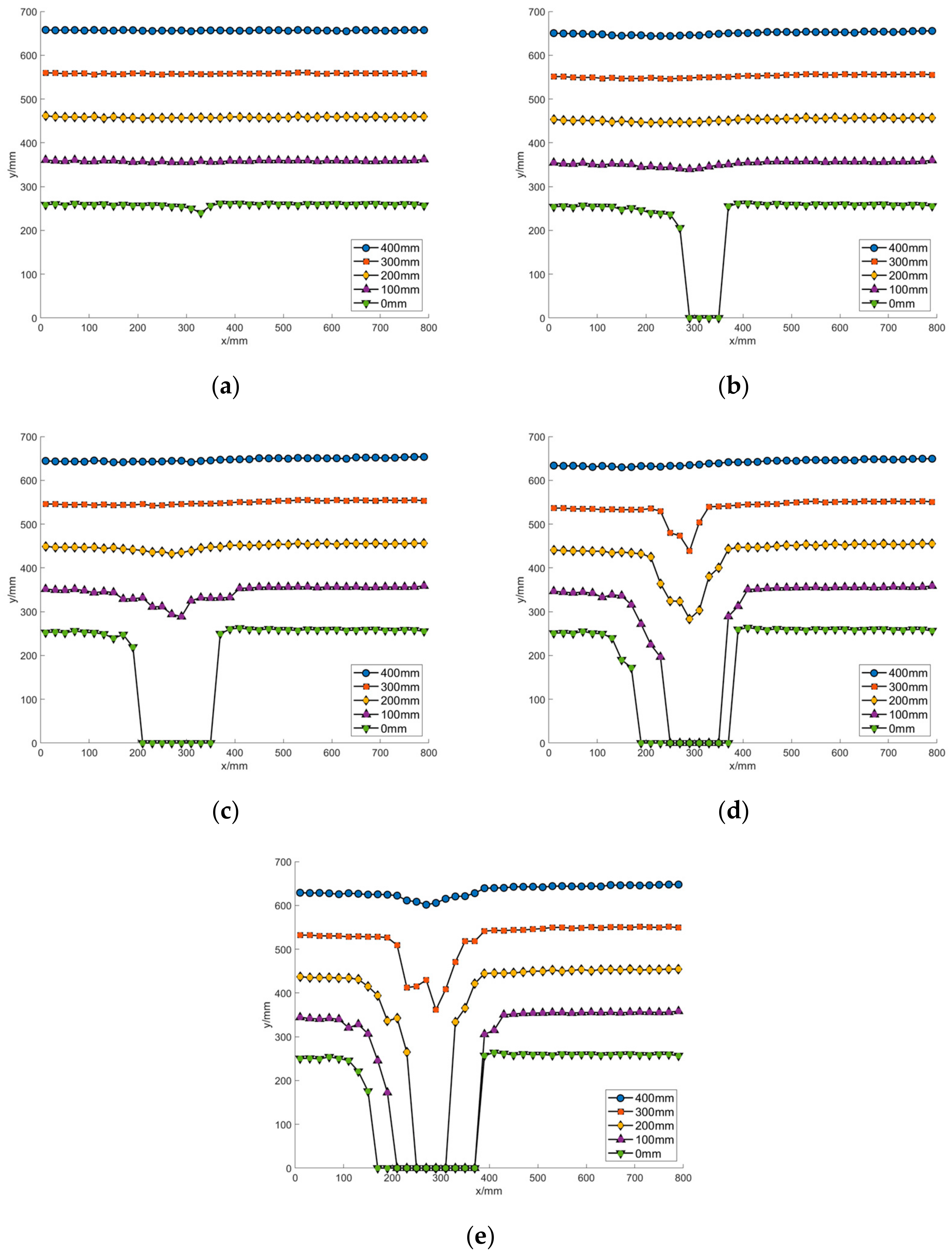
- After the leakage, the layer at a height of 0 mm (i.e., the top of the tunnel) started to subside. The layers at other heights above the tunnel remained stable, as shown in Figure 11a.
- (2)
- After the formation of the initial soil cave, the particles at 0 mm above the tunnel were lost, and the stratum at the height of 100 mm subsided slightly, while the stratum above 100 mm remained stable, as shown in Figure 11b.
- (3)
- After the formation of the secondary soil cave, the subsidence range of the stratum expanded. The stratum at the height of 300 mm started to subside, and the stratum at the height of 400 mm remained stable, as shown in Figure 11c.
- (4)
- After the formation of the third soil cave, the strata above the tunnel at the height of 0 mm~300 mm all settled downward visibly, but there was only a slight settlement on the strata surface, as shown in Figure 11d.
- (5)
- After the destabilization of the third soil arch, the strata at a height of 400 mm, i.e., the strata surface, started to subside downwards, as shown in Figure 11e.
4.2. Structural Response
4.2.1. Distribution of Earth Pressure
- (1)
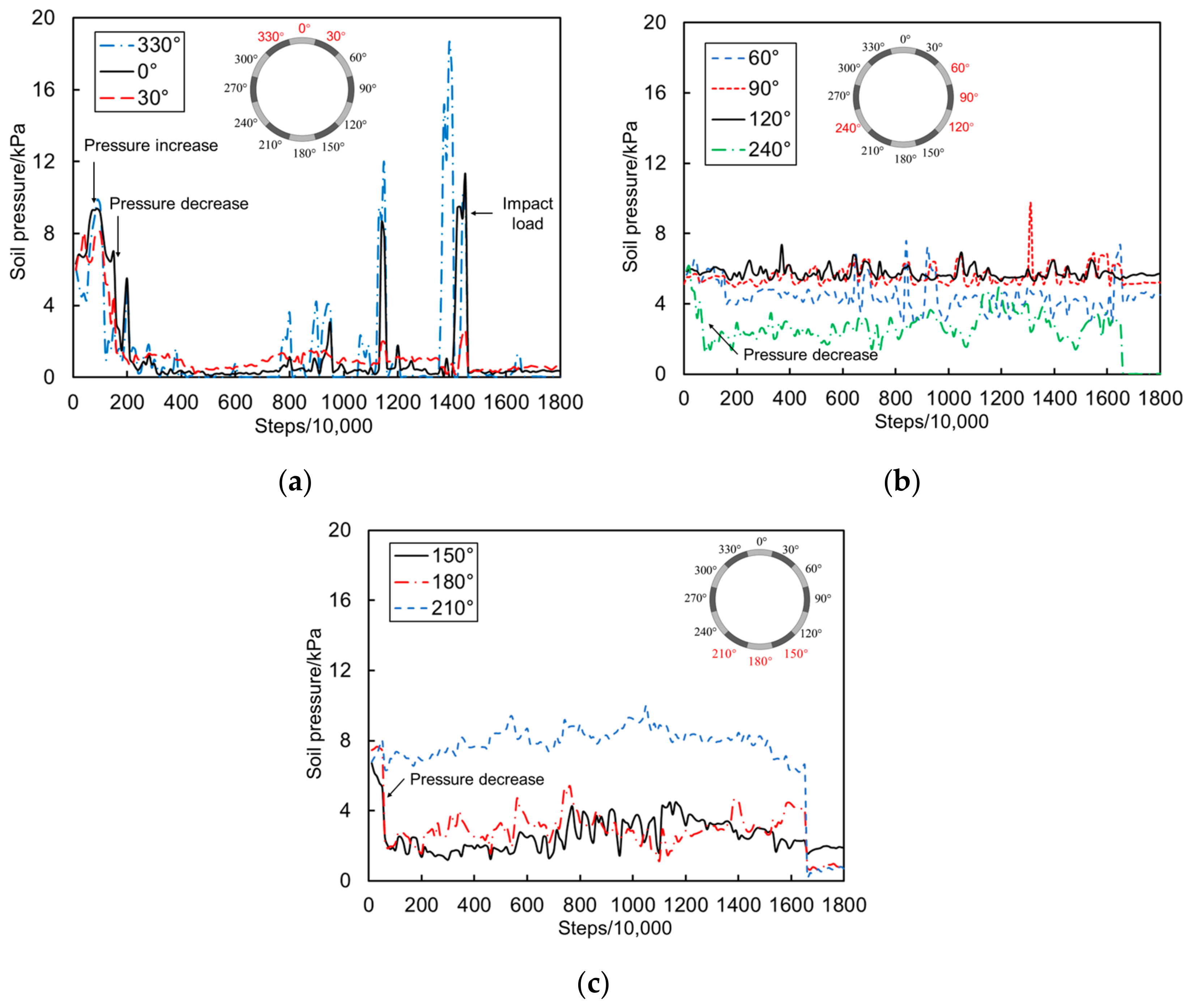
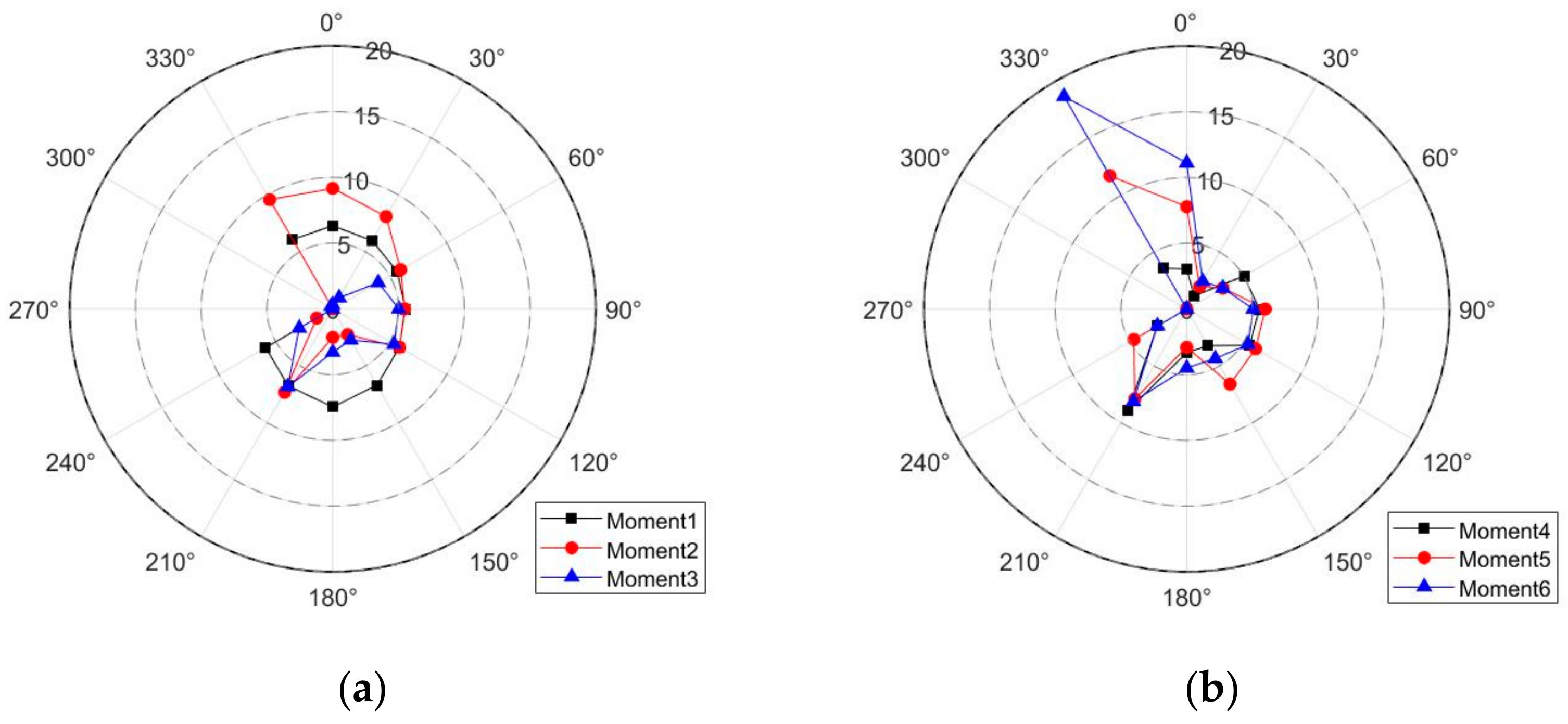
- Moment 1: The moment when the leakage started was chosen as the moment 1. The initial pressure is shown in Figure 13a. From the load distribution, it can be seen that the external load distribution of the tunnel at moment 1 was relatively uniform, with larger loads at the top and bottom of the tunnel and smaller loads at the waist.
- (2)
- Moment 2: the moment when the initial soil arch formed was chosen as moment 2. The load at the top and bottom of the tunnel increased significantly due to the soil arching effect, as shown in Figure 13a.
- (3)
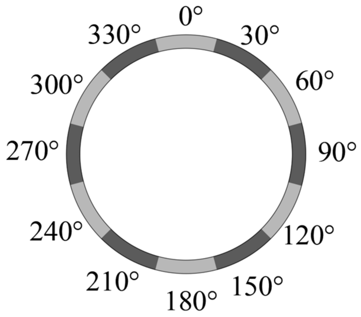
- Moment 3: the moment when the initial soil arch was destabilized was chosen as moment 3. At this moment, the top of the tunnel was completely within the soil cave, and the loads were decreased to the lowest value. Since the soil erosion had not yet progressed to other locations of the tunnel, the loads at other locations of the tunnel were relatively stable. The supports of the arch were at the 210° location, and the loads were larger than those at other locations, as shown in Figure 13a.
- (4)
- Moment 4: at this moment, the top of the tunnel was subjected to the first impact load, while the bottom pressure reached its peak due to the soil arch feet, but the back side of the tunnel opening was relatively stable, as shown in Figure 13b.
- (5)
- Moment 5: the moment of the second impact load was chosen as moment 5. The load at the top 0° and 330° increased significantly, as shown in Figure 13b.
- (6)
- Moment 6: at this moment, the third impact load was applied to the tunnel. The loads at the top 0° and 330° reached the peak, while the loads at other locations remained relatively stable, as shown in Figure 13b.
4.2.2. Tunnel Collapse Process
- (1)
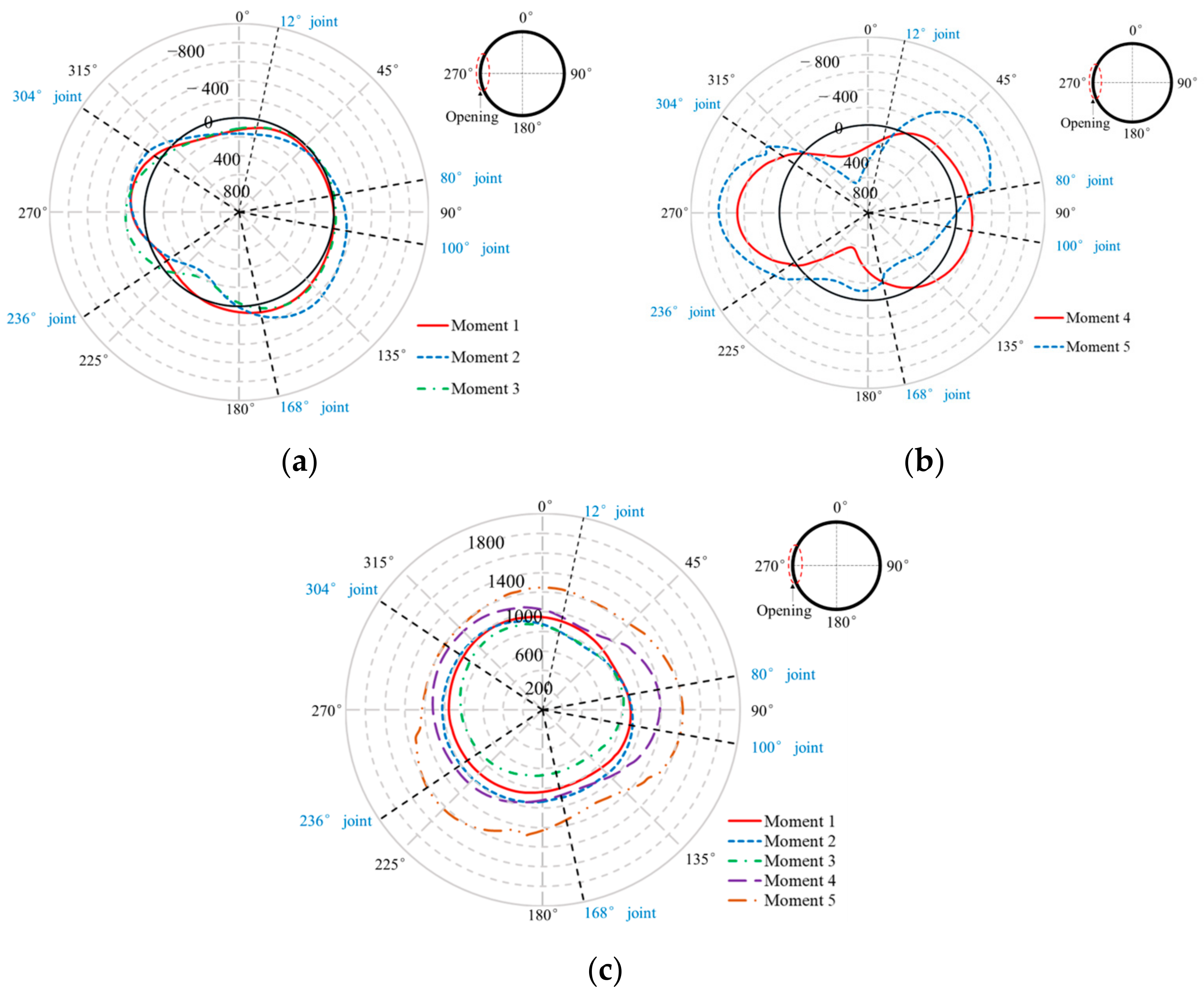
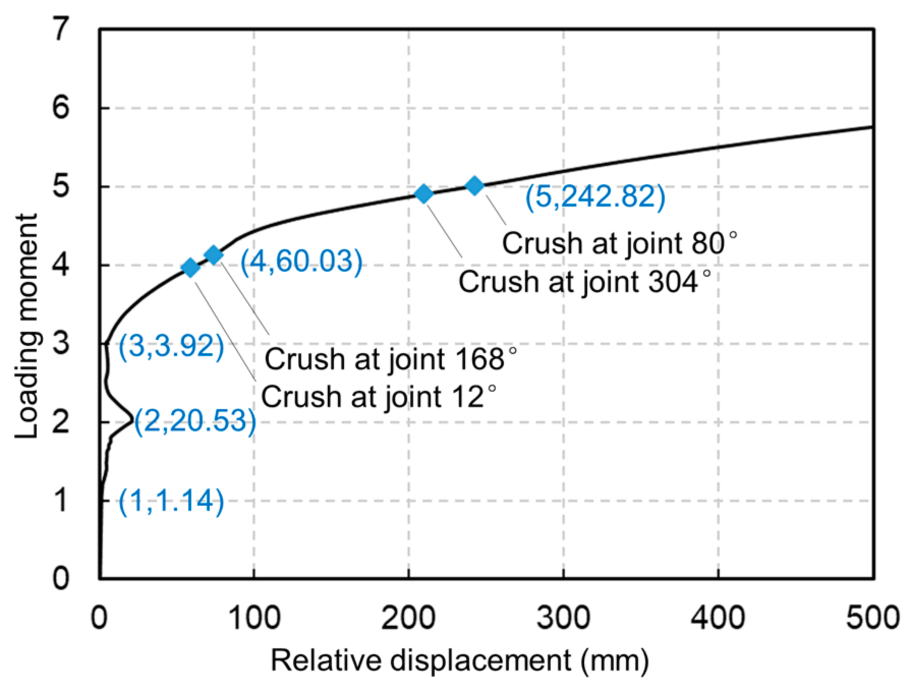
- Moment 1: at this time, the tunnel was subjected to normally distributed external soil and water pressure, which resulted in a 1.14 mm top–bottom convergence, and no structural damage had occurred yet.
- (2)
- Moment 2: with the formation of the initial soil arch, the load at the top and bottom of the tunnel increased significantly. Under the dual effects of waist load decrease and top and bottom loads increase, the bending moment generated at moment 2 increased significantly, thus leading to large top and bottom convergence deformation of 20.53 mm.
- (3)
- Moment 3: after the initial soil arch destabilization, the pressure at the top of the tunnel decreased. Therefore, the bending moment decreased, resulting in the relative displacement between the top and bottom of the tunnel decreasing to 3.92 mm.
- (4)
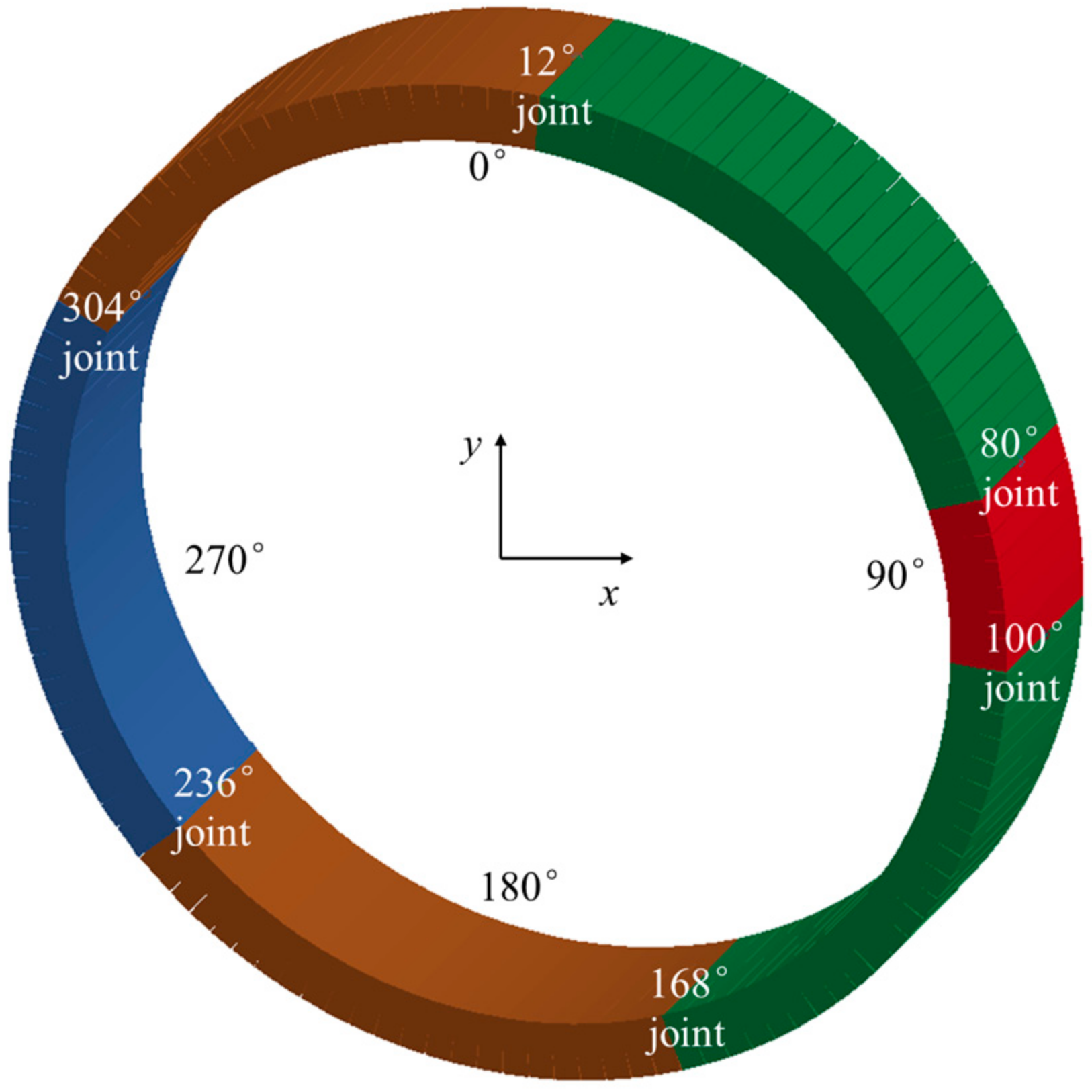
- Moment 4: after the first impact load was applied to the top of the tunnel, the load on the top of the tunnel increased suddenly, and the bending moments of the top and bottom of the tunnel and the waist of the tunnel increased significantly, resulting in the crushing of the gypsum at the 12° and 168° joints.
- (5)
- Moment 5: after the second impact load was applied to the top of the tunnel, the gypsum of the 80° and 304° joints at the waist of the tunnel was crushed. Up to now, four plastic hinges appeared in the tunnel and the tunnel was destabilized. At this time, the convergent deformation at the top and bottom of the tunnel had reached 242.82 mm.
5. Conclusions
- (1)
- A DEM-based coupled fluid–solid strata model combined with a nonlinear FEM tunnel model can be used to effectively simulate the complete process of tunnel leakage-induced collapse. By comparing with the tests, it was proved that the coupled fluid–solid model can be used to reproduce the phenomena of seepage erosion. By extracting the external loads of the tunnel obtained from the strata model and applying them to the FEM tunnel model, the tunnel collapse process can be simulated in a refined way, and the collapse mechanism of the tunnel structure can be obtained.
- (2)
- Based on the coupled fluid–solid analysis, it was pointed out that the microscopic mechanism of tunnel seepage-induced strata response was the continuous destabilization and reproduction of the soil arching effect formed by the soil particles. During the development of the soil arch, the height and width of the soil arch increased continuously, which led to the degradation of its stability and ultimately triggered the subsidence of the strata surface. On the one hand, the soil arching effect hinders the development of seepage erosion, so the erosion of the soil is limited to the interior of the soil arch, which is manifested as the generation of soil caves in the macroscopic phenomena; on the other hand, the soil arching effect temporarily supports the soil above, and there is no obvious subsidence of the strata surface in the process of erosion, which results in a sudden destabilization of the strata and impact loads on the tunnel.
- (3)
- The collapse process of the tunnel is as follows: firstly, due to the soil arching effect, the load outside the tunnel structure is redistributed, the loads at the feet of the arch rise significantly, the loads inside the soil arch dissipate, and the tunnel undergoes large deformation as a result; subsequently, due to the impact loads from the destabilization of the soil, the tunnel is damaged at several joints and generates plastic hinges, and ultimately the tunnel is destabilized and collapses.
Author Contributions
Funding
Institutional Review Board Statement
Informed Consent Statement
Data Availability Statement
Acknowledgments
Conflicts of Interest
References
- Fang, Q.; Zhang, D.; Wong, L. Shallow tunnelling method (STM) for subway station construction in soft ground. Tunn. Undergr. Space Technol. Inc. Trenchless Technol. Res. 2012, 29, 10–30. [Google Scholar] [CrossRef]
- Yu, C.; Zhou, A.; Chen, J.; Arulrajah, A.; Suksun Horpibulsuk, A. Analysis of a tunnel failure caused by leakage of the shield tail seal system. Undergr. Space 2019, 5, 105–114. [Google Scholar] [CrossRef]
- Cao, L.; Zhang, D.; Fang, Q.; Yu, L. Movements of ground and existing structures induced by slurry pressure-balance tunnel boring machine (SPB TBM) tunnelling in clay. Tunn. Undergr. Space Technol. 2020, 97, 103278. [Google Scholar] [CrossRef]
- Liang, Y.; Chen, X.; Yang, J.; Zhang, J.; Huang, L. Analysis of ground collapse caused by shield tunnelling and the evaluation of the reinforcement effect on a sand stratum. Eng. Fail. Anal. 2020, 115, 104616. [Google Scholar] [CrossRef]
- Yao, Q.; Di, H.; Ji, C.; Zhou, S. Ground collapse caused by shield tunneling in sandy cobble stratum and its control measures. Bull. Eng. Geol. Environ. 2020, 79, 5599–5614. [Google Scholar] [CrossRef]
- Wallis, S. Rebuilding the Red Line at St Petersburg. Tunn. Tunn. Int. 2002, 2, 461–469. [Google Scholar]
- Tan, Y.; Lu, Y.; Wang, D. Catastrophic Failure of Shanghai Metro Line 4 in July, 2003: Occurrence, Emergency Response, and Disaster Relief. J. Perform. Constr. Facil. 2021, 35, 04020125. [Google Scholar] [CrossRef]
- Liu, D.; Wang, F.; Hu, Q.; Huang, H.; Zhang, D. Structural responses and treatments of shield tunnel due to leakage: A case study. Tunn. Undergr. Space Technol. 2020, 103, 103471. [Google Scholar] [CrossRef]
- Hou, Y.; Qian, F.; Zhang, D.; Wong, L. Excavation failure due to pipeline damage during shallow tunnelling in soft ground. Tunn. Undergr. Space Technol. Inc. Trenchless Technol. Res. 2015, 46, 76–84. [Google Scholar] [CrossRef]
- Shen, X.; Yuan, D.; Cao, L.; Jin, D.; Chen, X.; Gao, Z. Experimental investigation of the failure of shield grease seals under the influence of environmental factors: A case study. Eng. Fail. Anal. 2022, 133, 105975. [Google Scholar] [CrossRef]
- Zheng, G.; Cui, T.; Cheng, X.; Diao, Y.; Zhang, T.; Sun, J.; Ge, L. Study of the collapse mechanism of shield tunnels due to the failure of segments in sandy ground. Eng. Fail. Anal. 2017, 79, 464–490. [Google Scholar] [CrossRef]
- Hu, Y.; Li, W.; Wang, Q.; Liu, S.; Wang, Z. Evolution of floor water inrush from a structural fractured zone with confined water. Mine Water Environ. 2019, 38, 252–260. [Google Scholar] [CrossRef]
- Qian, J.-G.; Zhou, C.; Yin, Z.-Y.; Li, W.-Y. Investigating the effect of particle angularity on suffusion of gap-graded soil using coupled CFD-DEM. Comput. Geotech. 2021, 139, 104383. [Google Scholar] [CrossRef]
- Xiong, H.; Yin, Z.-Y.; Zhao, J.; Yang, Y. Investigating the effect of flow direction on suffusion and its impacts on gap-graded granular soils. Acta Geotech. 2021, 16, 399–419. [Google Scholar] [CrossRef]
- Hu, J.; Ma, T.; Ma, K. DEM-CFD simulation on clogging and degradation of air voids in double-layer porous asphalt pavement under rainfall. J. Hydrol. 2021, 595, 126028. [Google Scholar] [CrossRef]
- Liu, Y.; Wang, L.; Hong, Y.; Zhao, J.; Yin, Z.Y. A coupled CFD-DEM investigation of suffusion of gap graded soil: Coupling effect of confining pressure and fines content. Int. J. Numer. Anal. Methods Geomech. 2020, 44, 2473–2500. [Google Scholar] [CrossRef]
- Wang, X.; Huang, B.; Tang, Y.; Hu, T.; Ling, D. Microscopic mechanism and analytical modeling of seepage-induced erosion in bimodal soils. Comput. Geotech. 2022, 141, 104527. [Google Scholar] [CrossRef]
- Zhou, C.; Qian, J.G.; Yin, Z.Y. Microscopic investigation of the influence of complex stress states on internal erosion and its impacts on critical hydraulic gradients. Int. J. Numer. Anal. Methods Geomech. 2022, 46, 3377–3401. [Google Scholar] [CrossRef]
- Liu, Y.; Wang, L.; Yin, Z.-Y.; Hong, Y. A coupled CFD-DEM investigation into suffusion of gap-graded soil considering anisotropic stress conditions and flow directions. Acta Geotech. 2022, 18, 3111–3132. [Google Scholar] [CrossRef]
- Hu, Z.; Li, J.; Zhang, Y.; Yang, Z.; Liu, J. A CFD–DEM study on the suffusion and shear behaviors of gap-graded soils under stress anisotropy. Acta Geotech. 2022, 18, 3091–3110. [Google Scholar] [CrossRef]
- Xiong, H.; Zhang, Z.; Sun, X.; Yin, Z.-y.; Chen, X. Clogging effect of fines in seepage erosion by using CFD–DEM. Comput. Geotech. 2022, 152, 105013. [Google Scholar] [CrossRef]
- Zhang, D.-M.; Gao, C.-P.; Yin, Z.-Y. CFD-DEM modeling of seepage erosion around shield tunnels. Tunn. Undergr. Space Technol. 2019, 83, 60–72. [Google Scholar] [CrossRef]
- Qian, J.-G.; Li, W.-Y.; Yin, Z.-Y.; Yang, Y. Influences of buried depth and grain size distribution on seepage erosion in granular soils around tunnel by coupled CFD-DEM approach. Transp. Geotech. 2021, 29, 100574. [Google Scholar] [CrossRef]
- Tang, Y.; Chan, D.H.; Zhu, D.Z. A coupled discrete element model for the simulation of soil and water flow through an orifice. Int. J. Numer. Anal. Methods Geomech. 2017, 41, 1477–1493. [Google Scholar] [CrossRef]
- Sun, Q.; Yihai Bao, X.L.; De Corte, W.; Taerwe, L. Experimental study on the leakage-induced structural collapse of segmental tunnels. Undergr. Space 2024. under review. [Google Scholar]
- de Frias Lopez, R.; Silfwerbrand, J.; Jelagin, D.; Birgisson, B. Force transmission and soil fabric of binary granular mixtures. Géotechnique 2016, 66, 578–583. [Google Scholar] [CrossRef]
- Dai, B.; Yang, J.; Luo, X. A numerical analysis of the shear behavior of granular soil with fines. Particuology 2015, 21, 160–172. [Google Scholar] [CrossRef]
- Zhu, H.P.; Zhou, Z.Y.; Yang, R.; Yu, A. Discrete particle simulation of particulate systems: Theoretical developments. Chem. Eng. Sci. 2007, 62, 3378–3396. [Google Scholar] [CrossRef]
- Carman, P.C. Flow of Gases through Porous Media; Butterworths Scientific Publications: London, UK, 1956. [Google Scholar]
- Zhou, H.; Wang, G.; Jia, C.; Li, C. A novel, coupled CFD-DEM model for the flow characteristics of particles inside a pipe. Water 2019, 11, 2381. [Google Scholar] [CrossRef]
- Itasca, Particle Flow Code in 2 Dimensions Online Manual Version 5.0; Itasca Consulting Group: Minneapolis, MN, USA, 2015.
- Itasca, F. Fast Lagrangian Analysis of Continua in 3-dimension (FLAC3D V 5.01); Itasca Consulting Group: Minneapolis, MN, USA, 2012. [Google Scholar]
- Deisman, N.; Mas Ivars, D.; Pierce, M. PFC2D Smooth joint contact model numerical experiments. Proc. GeoEdmonton 2008, 8, 1–8. [Google Scholar]
- Livermore Software Technology Corporation. LS-DYNA Keyword User’s Manual; Livermore Software Technology Corporation: Livermore, CA, USA, 2012. [Google Scholar]
- Liu, X.; Sun, Q.; Song, W.; Bao, Y. Numerical modeling and parametric study of hybrid fiber-rebar reinforced concrete tunnel linings. Eng. Struct. 2022, 251, 113565. [Google Scholar] [CrossRef]




| Soil Type | Content of Clay (%) | Cohesion (kPa) | Friction Angle (°) | Permeability Coefficient (m/s) | |
|---|---|---|---|---|---|
| Model soil | A | 0 | 0.34 | 40.17 | 2.21 × 10⁻³ |
| B | 5 | 1.81 | 35.56 | 1.33 × 10⁻⁴ | |
| C | 10 | 2.88 | 35.87 | 8.04 × 10⁻⁵ | |
| D | 20 | 4.28 | 34.16 | 6.45 × 10⁻⁵ | |
| Background case | / | 3.0 | 32.0 | 5.34 × 10⁻⁴ | |
| Parameters | Values |
|---|---|
| Particle density (kg/m3) | 2700 |
| Damping | 0.7 |
| Friction coefficient of particles | 0.8 |
| Tensile strength of particle contacts (Pa) | 36 |
| Shear strength of particle contacts (Pa) | 36 |
| Normal stiffness of particle contacts (N/m) | |
| Shear stiffness of particle contacts (N/m) | |
| Porosity of soils | 0.4 |
| Normal stiffness of contacts between wall and particles (N/m) | |
| Shear stiffness of contacts between wall and particles (N/m) | |
| Friction coefficient between wall and particles | 0.6 |
Disclaimer/Publisher’s Note: The statements, opinions and data contained in all publications are solely those of the individual author(s) and contributor(s) and not of MDPI and/or the editor(s). MDPI and/or the editor(s) disclaim responsibility for any injury to people or property resulting from any ideas, methods, instructions or products referred to in the content. |
© 2024 by the authors. Licensee MDPI, Basel, Switzerland. This article is an open access article distributed under the terms and conditions of the Creative Commons Attribution (CC BY) license (https://creativecommons.org/licenses/by/4.0/).
Share and Cite
Sun, Q.; Liu, X.; De Corte, W.; Taerwe, L. Numerical Simulation on the Leakage-Induced Collapse of Segmental Tunnels. Appl. Sci. 2024, 14, 3796. https://doi.org/10.3390/app14093796
Sun Q, Liu X, De Corte W, Taerwe L. Numerical Simulation on the Leakage-Induced Collapse of Segmental Tunnels. Applied Sciences. 2024; 14(9):3796. https://doi.org/10.3390/app14093796
Chicago/Turabian StyleSun, Qihao, Xian Liu, Wouter De Corte, and Luc Taerwe. 2024. "Numerical Simulation on the Leakage-Induced Collapse of Segmental Tunnels" Applied Sciences 14, no. 9: 3796. https://doi.org/10.3390/app14093796
APA StyleSun, Q., Liu, X., De Corte, W., & Taerwe, L. (2024). Numerical Simulation on the Leakage-Induced Collapse of Segmental Tunnels. Applied Sciences, 14(9), 3796. https://doi.org/10.3390/app14093796


