Abstract
In order to elucidate the impact of pressurized tubes’ structures on the sowing performance of pneumatic seed delivery systems, the EDEM–CFD coupled simulation method was employed to analyze the influence of pressurized tube parameters, including length (L), corrugation depth (S), corrugation width (K), and the number of corrugations, on seed movement characteristics, distribution uniformity, and airflow patterns. Simulation-validated experiments were conducted to study the impact of the optimal pressurized tube structure on seeding performance. The results indicate that pressurized tubes significantly enhance the uniformity coefficient of seed distribution, reduce seed velocity, and decrease the coefficient of variation in distribution uniformity. When pressurized tube parameters, specifically length (L), corrugation depth (S), corrugation width (K), and the number of corrugations, are set at 800 mm, 8 mm, 50 mm, and 6, respectively, the uniformity coefficient of seed distribution exceeds 95%, and the coefficient of variation in seed discharge consistency for each row is less than 3.2%. Moreover, the seed velocity at the outlet of the pressurized tube, the relative velocity of two-phase flow, and pressure loss are all minimal, indicating superior seeding performance. This research provides valuable insights into the analysis of seed movement characteristics within pressurized tubes and the optimization of their structural parameters.
1. Introduction
Pneumatic seed delivery systems, characterized by their adaptability to high speeds, wide coverage, and diverse seed types, are extensively employed in the sowing of various crops [,]. Pressurized tubes are essential components of pneumatic seed delivery systems, serving to disrupt and disperse seeds and promote the uniform distribution of the air-seed two-phase flow before entering the distribution head. They play a crucial role in influencing the seeding quality of pneumatic seeders [,]. On one hand, they contribute to achieving superior seeding results and increasing seed utilization. On the other hand, by enhancing distribution uniformity while ensuring smooth seed transport, they enable a corresponding reduction in airflow velocity, which aids in energy conservation and, to some extent, diminishes the power consumption of pneumatic seeders [,]. Research by Elyyan et al. [] suggests that the internal wall structure of pressurized tubes, such as corrugations, compensating strip patterns, and louver patterns, can induce continuous self-vibration in the airflow, leading to the agitation of seed movement and promoting uniform seed distribution. Daniel W. Kelm and others [] found that, compared to pressurized tubes with inlet and outlet diameters equal to the pipe diameter, variations in the inlet and outlet diameters of louver-type pressurized tubes are more conducive to improving seed distribution uniformity. Studies by Yu Wang and colleagues [] on louver shapes indicate that louver-type pressurized tubes, compared to ordinary circular pipes without louvers, can reduce the Reynolds number, increase the Nusselt number, and correspondingly increase the friction coefficient. Lei Xiaolong [] used the DEM–CFD coupled method to simulate and analyze the effects of corrugated pressurized tube parameters on the motion characteristics of wheat and canola seeds, the airflow distribution in pressurized tubes, and seed distribution uniformity. Through bench testing, they studied the influence of pressurized tube length, corrugation depth, corrugation width, and airflow pressure on seed distribution uniformity, determining the optimal pressurized tube structure. Yang Qinglu et al. [] investigated the impact of the diameter of corrugated pressurized tubes on the motion of gas–solid two-phase flow. They conducted an analysis of the number of collisions between fertilizer particles and the pressurized tube wall, the number of collisions between fertilizer particles, and the differential distribution of fertilizer particle density, ultimately determining the optimal pressurized tube diameter. Pressurized tube structures mainly encompass corrugations, louvers, varying diameters, and plain circular pipes, in which corrugated pressurized tubes find wider applications []. Researchers have undertaken the design and analysis of corrugated pressurized tube structures, and calculations have been conducted on pressure losses [,]. However, the movement of seeds within the airflow field of the pressurized tubes is inherently complex, posing challenges for the accurate description and analysis of seed movement characteristics.
Due to the intricate nature of the gas–solid two-phase flow formed by seeds in the seed delivery system, mathematical models face challenges in accurately describing seed movement characteristics and the airflow field. Therefore, the utilization of auxiliary software for analysis is necessary [,]. With the development of the discrete element method (DEM) and computational fluid dynamics (CFD), numerical simulation techniques have become crucial tools for studying multiphase flows. The DEM–CFD coupling simulation method is widely applied in areas such as fluidized beds, two-phase flow mixing, and pneumatic seed delivery systems [,]. Researchers have utilized the fluent simulation to analyze the airflow distribution in microconvex tubes and optimize their structures []. Studies have also been conducted on the pressure distribution and structural optimization of corrugated pressurized tubes []. However, these investigations primarily focus on single-phase flows, with limited research on the motion characteristics of two-phase flows within the pressurized tubes of pneumatic seed delivery systems []. In this study, to analyze the motion state of seeds within pressurized tubes and optimize their structures, we employ the DEM–CFD coupling method to analyze the movement characteristics and distribution uniformity of seeds under different pressurized tube structural parameters. This aims to elucidate the mechanisms influencing the uniformity and distribution of gas–solid two-phase flows. Furthermore, the experimental validation of simulation results is conducted on a test bench, providing insights for optimizing pressurized tube structural parameters and enhancing sowing uniformity.
2. Materials and Methods
2.1. Composition and Working Principle of Pneumatic Seed Delivery System
The pneumatic seed delivery system employs a “mechanical quantification of seed supply + airflow-based row-wise distribution” seeding method [,]. Its main components include the centralized seed distribution head, a fan, the seed–airflow mixing chamber, pressurized tubes, a distribution head, the seed delivery pipe, and seed flow monitoring sensors, as shown in Figure 1. The operational process is as follows: The centralized external groove wheel seeder quantitatively sows seeds in the seed box. The airflow generated by the fan serves as the carrier for transporting the air–seed two-phase flow. This two-phase flow passes successively through the seed–airflow mixing chamber and pressurized tubes to reach the distributor. The distributor evenly distributes the air–seed two-phase flow. It then passes through the seed delivery pipe and is deposited into the furrows opened by the furrow opener, completing the seeding operation.
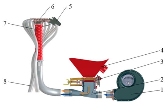
Figure 1.
Pneumatic conveying seed system. 1. Fan; 2. seed–air mixing chamber; 3. centralized seeder; 4. seed box; 5. sensor 6. distributor; 7. pressurized tube; 8. seed conduit.
2.2. Pressurized Tube Structure Design
The pressurized tube, a critical component connecting the seed–airflow mixing chamber and the distributor, plays a central role in improving the uniformity of seed distribution in the distributor. In this study, a corrugated pressurized tube was employed, as depicted in Figure 2. The main geometric parameters of this pressurized tube include the pressurized tube diameter (D), corrugation depth (S), corrugation width (K), and pressurized tube length (L). The pressurized tube is divided into two sections: a corrugated section (L1) with corrugations and a straight section (L2) without corrugations. By altering the geometric parameters of the pressurized tube, it is possible to modify the seed flow velocity and distribution within the pressurized tube. The use of numerical simulation techniques is an effective means to conserve processing costs and analyze seed migration trajectories.

Figure 2.
Pressurized tube structure diagram.
The inner diameter of the pressurized tube is calculated using the following formula:
where D is the pressurized tube diameter (m); Vf is the fluid volumetric flow rate (m3/h), with a maximum incoming airflow of 540 m3/h in the experimental setup; and u is the average fluid velocity (m/s), with an experimental value of 54 m/s at the inlet.
Calculating D results in D = 99.13 mm, which is rounded to 100 mm.
The movement of seeds in the pressurized tube involves turbulent motion. The surface structure of the pressurized tube disturbs the airflow, affecting the friction factor along the path and the distribution of the airflow within the pressurized tube. Pressure loss is a typical characteristic of the airflow movement within the pressurized tube. To determine the pressure loss within the pressurized tube, the Darcy friction factor is used and can be described as follows []:
where λ is the Darcy friction factor; Δp is the pressure loss between two sections (Pa); Dh is the relative diameter of the pressurized tube (mm); ρ is the density of air at working conditions (20 °C), 1.205 kg/m3; u is the airflow velocity (m/s); and Lz is the distance between two sections (mm).
As the airflow and seeds enter the pressurized tube after passing through the seed–airflow mixing chamber, their direction changes from horizontal to vertical. Seeds unavoidably collide with the inner wall of the pressurized tube, causing a decrease in seed velocity. Subsequently, seeds accelerate within the pressurized tube. Some seeds may collide with the corrugated surface, causing another reduction in seed velocity before resuming acceleration. This continues until seeds reach the distribution head. Throughout this motion process, it results in various pressure losses, including acceleration pressure loss within the pressurized tube, pure air pressure loss, gravity-induced pressure loss, pressure loss due to collision and friction among seeds, and pressure loss due to collision and friction between seeds and the pressurized tube wall [].
(1) Acceleration pressure loss:
where:
where Δpsa is the acceleration pressure loss (Pa); λsa is the acceleration pressure loss coefficient within the pressurized tube; μ is the material-to-air transport ratio, taken as 1.5; u is the critical velocity of wheat seeds (m/s); and v is the airflow velocity (m/s).
(2) Pure air pressure loss:
where Δpq is the pure air pressure loss (Pa); L is the pressurized tube length (mm); and D is the pressurized tube diameter (mm).
(3) Pressure loss due to gravity []:
where:
where Δpg is the gravity-induced pressure loss (Pa); λg is the gravity pressure loss coefficient; and ϕ is the theoretical velocity coefficient.
(4) Pressure loss due to material–wall collision friction []:
where Δpf is the pressure loss due to material–wall collision friction (Pa) and λs is the pressure loss coefficient due to material–wall impact friction, taken as 0.0032 for wheat.
(5) Pressure loss due to material–material collision []:
where Δpz is the pressure loss due to material–material collision (Pa) and λs is the pressure loss coefficient due to material–material friction.
2.3. Simulation Analysis of Gas–Solid Two-Phase Flow Based on DEM-Fluent
Due to the volume fraction of seeds in the airflow field is less than 10%, the EDEM–CFD coupling simulation employs the Eulerian–Lagrangian method. According to theoretical analysis, the forces exerted by the airflow on particles are modeled using the Freestream Equation for fluid resistance, along with the Saffman lift and Magnus lift models. The gas flow involves turbulent motion, and the simulation of the continuous phase airflow field employs the standard k-ε turbulence model. In the EDEM simulation, the Hertz–Mindlin no-slip contact model is selected, with a seeding rate of 100 g/s []. Boundary conditions and engineering objectives are essential for ensuring solvability and convergence. For the gas phase, the gas inlet is set as a velocity inlet with an airflow velocity of 21 m/s, as it is a high-speed gas flow. The gas–solid two-phase flow outlet is set as a pressure outlet, as it represents the exit of seeds and air after passing through the pressurized tubes and distribution head. In the simulation, the pressurized tube model is made of stainless steel. The material properties of seeds, stainless steel, and their mechanical characteristics, as well as the parameters of the airflow field, can be found in Table 1.

Table 1.
Simulation material parameters.
2.4. Experimental Design
2.4.1. Orthogonal Experimental Design
The theoretical analysis reveals that the parameters influencing seed movement characteristics within the pressurized tube and the airflow field are primarily related to the pressurized tube’s structural parameters. Therefore, simulation experiments were conducted to investigate the airflow characteristics within the pressurized tube for different structural parameters of the pressurized tube. The simulation experiments employed a four-factor, four-level orthogonal combinatorial design. The experimental factors included the number of corrugations (N), corrugation depth (S), corrugation width (K), and pressurized tube length (L), totaling four factors. The experimental factors and levels are presented in Table 2.

Table 2.
Experimental factor levels.
2.4.2. Simulation Validation Experiment Design
After determining the optimal structural parameters of the pressurized tube through orthogonal experiments, it is essential to conduct validation experiments to ensure the reasonableness of the optimal parameters. Initially, validation is performed through simulation. Since airflow velocity and seeding rate can affect the uniformity of airflow and seed distribution within the pressurized tube, simulation validation experiments for the optimal pressurized tube structure are conducted at different inlet airflow velocities (v) and seeding rates (x2). The experiments aim to investigate the impact of airflow velocity and seeding rate on seed distribution uniformity. The experiment design is detailed in Table 3.

Table 3.
Simulation verification experiment factor levels.
2.4.3. Bench Test
The experimental platform for the pneumatic seed delivery system was established based on the 2PST-type planter performance testing system at the National Key Laboratory of Soil–Plant Machinery System Technology, Chinese Academy of Agricultural Mechanization Sciences, as illustrated in Figure 3. The experimental setup incorporates an independent pneumatic seed delivery system. The platform utilizes a vortex-type air pump fan with a maximum speed of 2850 r/min, a maximum air pressure of 32 kPa, a maximum air volume of 9 m3/min, and a power of 5.5 kW. The inlet airflow velocity can be adjusted through a fan frequency converter, with a maximum frequency of 50 Hz. Seeds are discharged from the centralized planter and then enter the seed delivery system, with the seeding quantity controlled by adjusting the motor speed of the seed delivery shaft, where the motor’s maximum speed is 100 r/min.
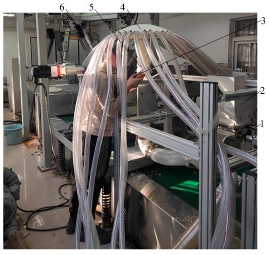
Figure 3.
Experimental platform for the seed delivery system. 1. Centralized planter; 2. seed box; 3. pressure measurement device; 4. distributor; 5. pressurized tubes; 6. seed-conveying tubes.
Before conducting pressure measurements, four holes of 4 mm in diameter were uniformly distributed at 90-degree intervals on the upper and lower parts of the pressurized tubes externally. During the pressure measurement process, care must be taken to ensure that the seed conveying tubes are not blocked to prevent potential increases in pressure loss. Pressure measurements are conducted after the stable operation of the seed delivery system. The measurement is repeated five times, and experimental data are recorded and used to calculate the pressure loss values.
3. Experimental Results and Discussion
3.1. Orthogonal Simulation Results and Analysis
Based on the coupled simulation, pressure distribution maps and seed distribution status maps within the pressurized tube were obtained. From these results, pressure loss values, seed distribution uniformity coefficients, and the coefficients of variation in discharge consistency for each row were extracted for different structural pressurized tubes. To accurately and intuitively assess the seeding performance of the pneumatic seed delivery system, the upper and lower parts of the pressurized tube’s pressure loss values and the seed distribution uniformity coefficient were selected as evaluation indicators for the structural optimization of the pressurized tube. The results of the orthogonal simulation experiments are presented in Table 4.

Table 4.
Orthogonal experimental results.
3.1.1. Study on Seed Distribution Uniformity
To investigate the distribution of wheat seeds after passing through the pressurized tube and the influence of the pressurized tube structure on seeding performance, the entrance of the pressurized tube into the distribution head was selected as the seed distribution statistics frame in the EDEM(2020) software (shown as Figure 4).
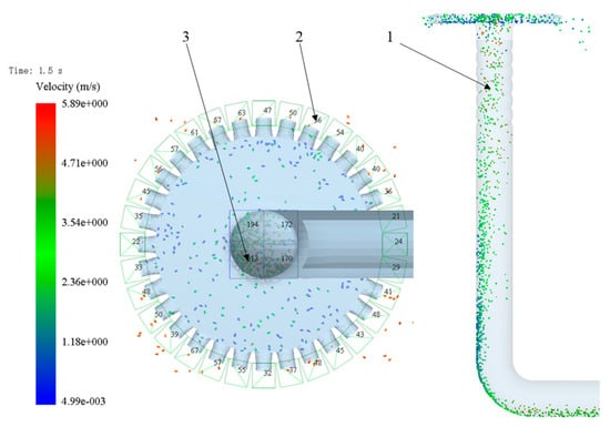
Figure 4.
Seed distribution status statistics. 1. Pressurized tube; 2. outlet; 3. seed-counting frame at the upper part of the pressurized tube.
This area was divided into four equal parts along the pressurized tube’s axial direction, and the number of seeds passing through the same region in the same time period was counted as Qi (i = 1, 2, 3, 4). The seed distribution uniformity coefficient was then calculated using the following formula:
where k is the seed distribution uniformity coefficient (%); Qi is the number of wheat seeds in the i-the region of the statistics frame (i = 1, 2, 3, 4); and is the average number of wheat seeds in the statistics frame.
Seed quantities at each seeding outlet of the distribution head were counted using seed statistics frames, and the coefficients of variation in discharge consistency for each row were calculated. The results are shown in Table 5.

Table 5.
Analysis of variance for experimental results.
3.1.2. Pressure Distribution within the Pressurized Tube
Pressure distribution contour plots within the pressurized tube for different structural configurations were obtained through post-processing using CFD-Post(14.0) software, as shown in Figure 5. In the straight segments of the pressurized tubes, the pressure distribution is uniform and pressure losses are relatively small, with consistent upper and lower pressure. When corrugations appear, pressure changes occur. The central pressure decreases, while the pressure at the pressurized tube wall increases. The depth of the corrugations affects the pressure changes, with deeper corrugations resulting in more pronounced pressure variations. Pressure losses within the pressurized tube also increase with longer pressurized tube lengths and a higher number of corrugations. As corrugation width increases, the pressure changes within the corrugated section first decrease and then increase.
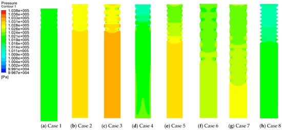
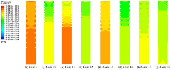
Figure 5.
Pressure distribution cloud map inside the baffle.
Through variance analysis, it is evident that corrugation depth, corrugation width, corrugation count, and pressurized tube length have p-values of less than 0.05 for both the pressure difference and distribution uniformity coefficient, indicating their significant influence. Furthermore, the primary and secondary order of impact on pressure difference is pressurized tube length > corrugation count > corrugation width > corrugation depth, while the primary and secondary order of impact on the distribution uniformity coefficient is corrugation depth > corrugation width > corrugation count > pressurized tube length.
By conducting variance analysis on the experimental results and determining the primary and secondary orders of the factors’ impact on pressure loss and distribution uniformity coefficient, a further single-factor mean analysis was performed to determine the optimal structural parameters of the pressurized tube. The results of the single-factor mean analysis are presented in Table 6.

Table 6.
Single-factor mean analysis.
In the context of pressure loss, lower pressure loss results in reduced energy loss in the seeding system, indicating better seeding performance. Based on the comprehensive analysis of single-factor mean pressure loss, the minimum pressure loss value was achieved with a corrugation depth of 4 mm, corrugation width of 50 mm, corrugation count of 4, and a pressurized tube length of 700 mm. However, having too few corrugations can lead to an uneven airflow distribution within the vane, resulting in decreased seed distribution uniformity. A pressurized tube that is too short may not facilitate the uniform mixing of air and seeds, leading to reduced seed distribution uniformity. A shallow corrugation depth may not adequately disperse the two-phase airflow of air and seeds, reducing the distribution uniformity of the seeding system.
Regarding the distribution uniformity coefficient, a larger coefficient indicates lower variation in the consistency of row discharge, signifying better seeding performance. Based on the comprehensive analysis of single-factor mean distribution uniformity coefficient, the largest coefficient, meaning the lowest variation in row discharge consistency, was achieved with a corrugation depth of 6 mm, corrugation width of 40 mm, corrugation count of 10, and a pressurized tube length of 1000 mm. However, considering the issue of pressure loss in the seeding system, longer pressurized tube lengths result in higher pressure losses, leading to energy wastage. An increase in corrugation depth, while increasing pressure loss, may also raise seed breakage rates, affecting seeding efficiency.
Through orthogonal experiments, the optimal parameter combination was determined to be a pressurized tube length of 800 mm, corrugation depth of 8 mm, corrugation count of 6, and corrugation width of 50 mm.
3.2. Simulation Validation Experiments
Multi-factor simulation experiments were conducted under the optimal pressurized tube structural parameters. After processing the simulation results, the seed velocity, airflow velocity, pressure loss, distribution uniformity coefficient, and the coefficients of variation for row discharge consistency were obtained. The specific data are presented in Table 7.

Table 7.
Simulation experiment results.
3.2.1. Velocity Vector Distribution
As shown in Figure 6, under different inlet airflow velocities, airflow is uniformly distributed within the pressurized tube, and the trend of velocity variations within the vane is generally consistent. In the straight section of the pressurized tube, there is some variation in airflow velocity, with the inner side of the bend a having higher airflow velocity and the outer side having a relatively lower airflow velocity. However, as the inlet airflow velocity increases, the differences in airflow velocity within the straight section decrease. As the airflow flows into the corrugated section, the change in pipe diameter results in an increase in airflow velocity. Aside from the region near the pipe wall, where the velocity is lower, the airflow velocity at other positions within the vane is essentially uniform. This indicates that this structural design can enhance the uniform distribution of airflow within the vane, ensuring the seeding system’s seeding performance.
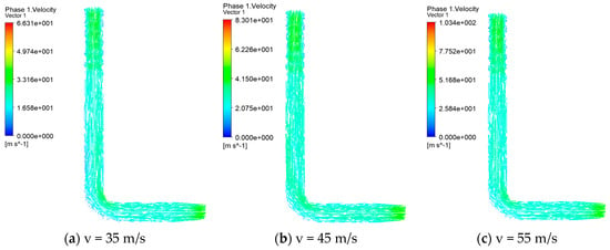
Figure 6.
Airflow field distribution at different inlet air velocities.
3.2.2. Pressure Distribution
The pressure distribution within the pressurized tube under different inlet airflow velocities is shown in Figure 7. In the straight section of the pressurized tube, the pressure variation is relatively small at different inlet airflow velocities. However, with an increase in inlet airflow velocity, the pressure difference in the straight section shows an initial increase followed by a decrease. Therefore, it is necessary to choose an appropriate inlet airflow velocity to reduce unnecessary energy consumption.
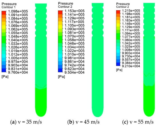
Figure 7.
Pressure distribution contour map.
In the corrugated section, the pressure is nearly uniform at all locations, without abrupt changes. However, with an increase in inlet airflow velocity, the overall pressure within the vane gradually increases, leading to a larger pressure difference and increased pressure loss. This suggests that it is essential to determine an appropriate inlet airflow velocity to reduce energy consumption while ensuring the smooth transport of seeds. An analysis of the pressure distribution contour plots within the vane indicates that the structural parameters of this pressurized tube ensure the stability of airflow velocity within the vane, thereby enhancing the seeding performance of the seeding system.
3.2.3. Seed Distribution within the Pressurized Tube
The distribution of seeds within the pressurized tube is shown in Figure 8 under different inlet airflow velocities and seeding quantities. In the straight section, some seeds initially move along the outer side of the vane’s wall. As the airflow acts on the seeds, they accelerate and gradually disperse throughout the entire pressurized tube. After passing through the corrugated section of the pressurized tube, the presence of corrugations causes an increase in seed velocity. The disturbance from the corrugations ensures that seeds are uniformly distributed in the middle part of the corrugated section, thus ensuring the uniformity of seed flow into the distribution head.
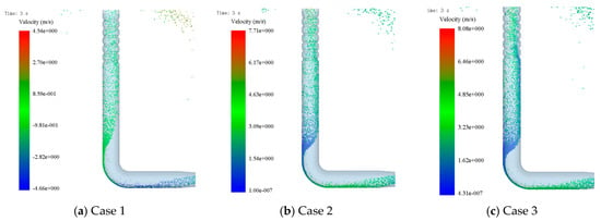
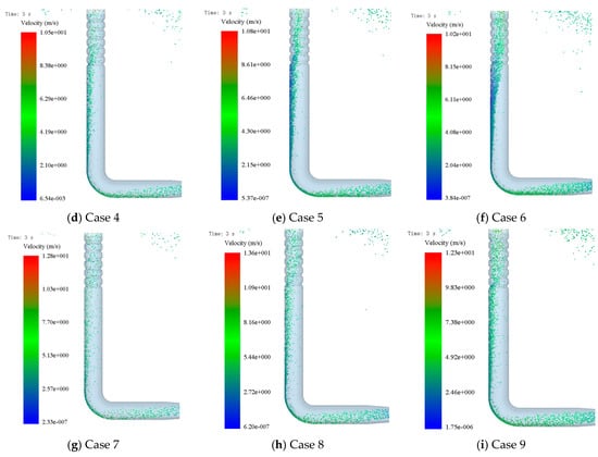
Figure 8.
Seed distribution inside the pressurized tube.
Under the same seeding quantity, with an increase in the inlet airflow velocity, the uniformity coefficient of seed distribution within the pressurized tube initially decreases and then increases. When the inlet airflow velocity reaches 35 m/s, seeds gradually move towards the center of the pressurized tube, and seed distribution becomes more dispersed. The distance over which seeds move along the vane’s straight section wall is the shortest. However, when the inlet airflow velocity reaches 55 m/s, the distance over which seeds move along the straight section wall increases, leading to reduced uniformity of seed distribution within the corrugated section and a decrease in seeding system performance. Therefore, in the design of seeding systems and the selection of fans, it is advisable to minimize the inlet airflow velocity as long as it meets the seed transport requirements. Under the same inlet airflow velocity, with an increase in seeding quantity, seed velocity gradually decreases, and the uniformity coefficient of seed distribution within the pressurized tube shows a trend of initially decreasing and then increasing.
3.3. Bench Test
A comprehensive experimental investigation was conducted based on the factor level table, and the results are summarized in Table 8.

Table 8.
Experimental design and results.
Through a systematic investigation with varying inlet airflow velocities and seeding quantities, the pressure loss values for the optimized seed delivery system with pressurized tubes were determined through experimental tests and calculations, demonstrating a similar trend to the simulated values. Comparative analysis with simulation results revealed that pressure loss decreases initially and then increases with increasing inlet airflow velocity and seeding quantity. Discrepancies between experimental and simulated pressure loss values were observed, primarily attributed to issues related to the experimental setup’s sealing and the material properties of the pressurized tubes’ inner walls. Further analysis indicated that the optimized pressurized tubes effectively reduced pressure losses, enhanced seed distribution uniformity, and, consequently, reduced the coefficient of variation in seed quantities across rows.
4. Conclusions
This study focused on the structural design and optimization of the air-assisted seeding system’s pressurized tubes (or diffusers). By examining the influence of pressurized tube structure on the uniformity of seed distribution within the seeding system, we employed a coupled simulation approach to investigate the motion behavior and characteristics of wheat seeds inside the pressurized tubes. Our analysis unveiled the underlying mechanisms affecting the uniformity and distribution consistency of the gas–solid two-phase flow. Through orthogonal experimental analysis, we evaluated the effects of different pressurized tube structures on seed distribution uniformity, pressure loss, and the coefficient of variation in discharge rates for various rows. Key findings and conclusions are as follows.
In response to the challenge of inadequate seed distribution uniformity within the air-assisted seeding system, a pressurized tube structural optimization was carried out using an orthogonal experimental design. Theoretical analysis was employed to investigate the mechanisms behind pressure loss within the pressurized tubes.
The optimization of the pressurized tube structure via coupled simulation resulted in minimized variations in gas flow velocity and reduced turbulence effects. Furthermore, the pressure loss was effectively reduced. Under various inlet gas flow rates and seeding quantities, the coefficient of variation in discharge rates for all rows was limited to a maximum of 3.12%, meeting standard requirements. The results from the analysis indicated that the primary and secondary factors affecting pressure differences were the pressurized tube length, corrugation quantity, corrugation width, and corrugation depth. Regarding the coefficient of variation in distribution uniformity, the dominant influencing factors were corrugation depth, corrugation width, corrugation quantity, and pressurized tube length. Based on the combination of variance analysis and single-factor mean analysis, the optimal parameters for the pressurized tubes were determined to be a pressurized tube length of 800 mm, corrugation depth of 8 mm, corrugation quantity of 6, and corrugation width of 50 mm.
The coupled simulation analysis revealed that, under identical seeding quantities and within a certain range of inlet gas flow rates, an increase in inlet gas flow velocity led to initial reductions in both the coefficient of variation for seed distribution uniformity and pressure loss. This suggests that the choice of inlet gas flow velocity plays a significant role in the seeding system’s performance, offering valuable insights for the design of air-assisted seeding systems.
Validation through simulation experiments confirmed that the optimized pressurized tube structure consistently met the requirements for the coefficient of variation in discharge rates under varying inlet gas flow rates and seeding quantities. This optimization effectively reduced turbulence, minimized pressure loss, and improved the uniformity of seed distribution within the seeding system. These findings serve as a theoretical foundation for the design of subsequent components in air-assisted seeding systems.
Author Contributions
Conceptualization, J.Z. and Y.L.; methodology, J.Z.; software, L.L.; validation, Z.L.; formal analysis, Y.L.; investigation, L.L.; resources, Z.L. and Y.L.; data curation, J.Z. and Y.L.; writing original draft preparation, J.Z.; writing review and editing, Z.L.; visualization, Z.L.; supervision, L.L.; project administration, L.L.; funding acquisition, L.L. All authors have read and agreed to the published version of the manuscript.
Funding
This work was mainly supported by the China National Machinery Industry Corporation youth fund—Research on pneumatic seeding for seed and fertilizer based on multi-channel section control—QNJJ-PY-2022-05.
Institutional Review Board Statement
Not applicable.
Informed Consent Statement
Informed consent was obtained from all subjects involved in the study.
Data Availability Statement
The data presented in this study are available in article.
Conflicts of Interest
Author J.Z. was employed by the company “Chinese Academy of Agricultural Mechanization Science Group Co., Ltd.”. The remaining authors declare that the research was conducted in the absence of any commercial or financial relationships that could be construed as a potential conflict of interest.
References
- Hilton, J.E.; Cleary, P.W. The influence of particle shape on flow modes in pneumatic conveying. Chem. Eng. Sci. 2011, 66, 231–240. [Google Scholar] [CrossRef]
- Chang, J.; Zhang, X. Design and test of one-step centralized type pneumatic conveying system. Trans. CSAE 2011, 27, 136–141. [Google Scholar]
- Peng, C.; Zhang, X.; Hou, C.; Bai, P.; Wang, Z. Design on test-bed of centralized pneumatic seed metering device. J. Chin. Agric. Mech. 2017, 38, 32–36. [Google Scholar]
- Yang, H.; Liu, L.; Zhou, J.; Zhao, Z.; Zhao, J. Analysis of air seed drill current situations and using situation in China. J. Agric. Mech. Res. 2013, 35, 216–220. [Google Scholar]
- Ashraf, M.; Tian, S.; Kondo, N.; Shigi, T. Machine Vision to Inspect Tomato Seedlings for Grafting Robot. Acta Hortic. 2014, 1054, 309–316. [Google Scholar] [CrossRef]
- Dimotakisp, E.; Lyer, C.; Papantonioud, Z. Viscous Flow in Pipes. In Fundamentals of Fluid Mechanics; Bruce, R.M., Ed.; Department of Aerospace Engineering and Engineering Mechanics: New York, NY, USA, 2009; pp. 383–460. [Google Scholar]
- Elyyan, M.A.; Rozati, A.; Tafti, D.K. Investigation of dimpled fins for heat transfer enhancement in compact heat exchangers. Int. J. Heat Mass Transf. 2008, 51, 2950–2966. [Google Scholar] [CrossRef]
- Daniel, W.K. Distribution Tube for Pneumatic Applicator. U.S. Patent 4575284, 11 March 1989. [Google Scholar]
- Wang, Y.; He, Y.-L.; Lei, Y.-G.; Zhang, J. Heat transfer and hydrodynamics analysis of a novel dimpled tube. Exp. Therm. Fluid Sci. 2010, 34, 1273–1281. [Google Scholar] [CrossRef]
- Lei, X.; Liao, Y.; Zhang, W.; Li, S.; Wang, D.; Liao, Q. Simulation and Experiment of Gas-Solid Flow in Seed Conveying Tube for Rapeseed and wheat. Trans. Chin. Soc. Agric. Mach. 2017, 48, 57–68. [Google Scholar]
- Yang, Q.; Li, Z.; Li, H.; He, J.; Wang, Q.; Lu, C. Numerical analysis of particle motion in pneumatic centralized fertilizer distribution device based on CFD-DEM. Trans. Chin. Soc. Agric. Mach. 2019, 50, 81–89. [Google Scholar]
- Bourges, G.; Medina, M. Air-seeds flow analysis in a Distribution head head of an “air drill” Seeder. Acta Hortic. 2013, 1008, 259–264. [Google Scholar] [CrossRef]
- Liu, Y. Design and Experiment of Pressure Balance Device for Pneumatic Conveying System; Chinese Academy of Agricultural Mechanization Science: Beijing, China, 2019. [Google Scholar]
- Li, Y.; Liu, Y.; Liu, L. Distribution mechanism of airflow in seed tube of different lengths in pneumatic seeder. Trans. Chin. Soc. Agric. Mach. 2020, 51, 55–64. [Google Scholar]
- Dai, Y.; Luo, X.; Wang, Z.; Zeng, S.; Zang, Y.; Yang, W.; Zhang, M.; Wang, B.; Xing, H. Design and experiment of rice pneumatic centralized seed Distribution head. Trans. CSAE 2016, 32, 36–42. [Google Scholar]
- Peng, Y.; Gu, S.; Chu, Q.; Zhang, Q.; Xu, X.; Li, B.; Wang, Y. Design of Stock Feeding Device of Grafting Robot for Solanaceae. Trans. Chin. Soc. Agric. Eng. 2016, 32, 76–82. [Google Scholar]
- Guan, J.; Pei, X.; Zhang, L. Research on flow characteristics of pneumatic conveying in dense phase stepped pipeline of grain Particles. China Powder Sci. Technol. 2018, 24, 38–43. [Google Scholar]
- Wen, X.; Jia, H.; Zhang, S.; Yuan, H.; Wang, G.; Chen, T. Test of suspension velocity of granular fertilizer based on EDEM-Fluent coupling. Trans. Chin. Soc. Agric. Mach. 2020, 51, 69–77. [Google Scholar]
- Kai, J.; Wang, J.; Li, C. Design and test of melon grafting device based on splice grafting. Int. Agric. Eng. J. 2018, 27, 65–74. [Google Scholar]
- Tang, H.; Xu, F.D.; Xu, C.S.; Zhao, J.L.; Wang, Y.J. The influence of a seed drop tube of the inside-filling air-blowing precision seed-metering device on seeding quality. Comput. Electron. Agric. 2023, 204, 107555. [Google Scholar] [CrossRef]
- Bao, Y.F.; Wang, F.Y.; Jiang, J.T.; Chen, F. Research progress and development trend of precision seeding equipment for vegetable seeds. J. Agric. Mechan. Res. 2021, 43, 247–254. [Google Scholar]
- Zhao, J.; Liu, L.; Yang, X.; Du, J.; Zhao, Z. Design and experiment of pneumatic seeding system of teff seeder. Trans. Chin. Soc. Agric. Mach. 2018, 49 (Suppl. S1), 101–107. [Google Scholar]
- Li, L.; Meng, Z.; Wang, X.; An, X.; Wang, P.; Wu, G. Simulation analysis of gas-solid two fhase flow in pneumatic conveying fertilizer feeder of rice fertilizer applicator. Trans. Chin. Soc. Agric. Mach. 2018, 49, 171–180. [Google Scholar]
- Li, F.; He, D. Research on the moving regularity of seeds in pneumatic pipes. Act. Univ. Sept. Occi. Agric. 1986, 14, 12–24. [Google Scholar]
- Li, Y.; Liu, R.; Liu, C.; Liu, L. Simulation and Test of Seed Velocity Coupling in Seed Tube of Pneumutic Seed Metering Device. Trans. Chin. Soc. Agric. Mach. 2021, 52, 54–61. [Google Scholar]
- Qin, J.; Zhang, X.; Chen, B.; Kong, A. Design and Test Research of Allotter in Centralized Pneumatic Seeding System. J. Agric. Mech. Res. 2007, 29, 131–133. [Google Scholar]
- Liu, Z.D.; Wang, Q.J.; Li, H.W.; He, J.; Lu, C.Y.; Yu, C.C. Fertilizer injecting route analysis and test for air-blowing seed-fertilizer hole-applicator via CFD-DEM coupling. Trans. CSAE 2019, 35, 18–125. [Google Scholar]
Disclaimer/Publisher’s Note: The statements, opinions and data contained in all publications are solely those of the individual author(s) and contributor(s) and not of MDPI and/or the editor(s). MDPI and/or the editor(s) disclaim responsibility for any injury to people or property resulting from any ideas, methods, instructions or products referred to in the content. |
© 2024 by the authors. Licensee MDPI, Basel, Switzerland. This article is an open access article distributed under the terms and conditions of the Creative Commons Attribution (CC BY) license (https://creativecommons.org/licenses/by/4.0/).