Article

Research on Mechanical Properties of Steel-Polypropylene Fiber-Reinforced Concrete after High-Temperature Treatments

1
College of Architecture and Civil Engineering, Kunming University, Kunming 650214, China
2
Faculty of Land Resource Engineering, Kunming University of Science and Technology, Kunming 650093, China
3
Faculty of Public Safety and Emergency Management, Kunming University of Science and Technology, Kunming 650093, China
*
Author to whom correspondence should be addressed.
Appl. Sci. 2024, 14(9), 3861; https://doi.org/10.3390/app14093861
Submission received: 27 March 2024 / Revised: 24 April 2024 / Accepted: 29 April 2024 / Published: 30 April 2024
(This article belongs to the Topic Complex Rock Mechanics Problems and Solutions)

Abstract

:
A mechanical property experiment was carried out on steel-polypropylene fiber-reinforced concrete after elevated temperatures by using a 50 mm diameter SHPB apparatus. The regulations of compressive strength, elastic modulus, Poisson’s ratio, and other mechanical properties under six heating temperature levels (normal temperature, 100 °C, 200 °C, 400 °C, 600 °C, and 800 °C) and three impact pressures (0.3 MPa, 0.4 MPa, 0.5 MPa) were studied. Using ANSYS/LS-DYNA 19.0 numerical simulation software and LS-PrePost post-processing software, numerical simulation analysis was conducted on the dynamic Hopkinson uniaxial impact compression and uniaxial dynamic impact splitting mechanical experiments of C40 plain concrete and steel-polypropylene hybrid fiber concrete. The results show that the dynamic compressive strength of hybrid fiber concrete with the optimal dosage reaches its maximum at a temperature group of 200 °C, and the dynamic compressive strength of hybrid fiber concrete with the optimal dosage increases by 97.1% compared to C40 plain concrete at a temperature group of 800 °C. The impact waveform and stress-strain curve results of the numerical simulation are very similar to the experimental results. The errors in calculating the peak stress and peak strain are within 6%, which can truly and accurately simulate the static mechanical properties and failure process of hybrid fiber-reinforced concrete.

1. Introduction

As a very economical and practical construction material, hybrid fiber-reinforced concrete (HyFRC) is widely used in bridge engineering, civil engineering, fortification, nuclear reactor containment, and other civil and military buildings. Due to the shortcomings of regular concrete, such as vulnerability to bursting from high temperatures, poor durability, and poor crack resistance and toughness, it cannot satisfy the high mechanical property requirements of engineering buildings [1]. Concrete modification research mainly involves the incorporation of fibers dispersed within the concrete during the preparation process to improve the shortcomings of regular concrete, such as large early shrinkage, low tensile strength, poor durability, and vulnerability to cracking [2,3]. HyFRC is a composite concrete material formed by mixing two or more different types of fibers into concrete, allowing for a combination of different fiber characteristics or complementary effects. It is the future research and development trend of fiber concrete modification, and the corresponding findings are of great value for the promotion and application of HyFRC materials in engineering applications [4].
In recent years, scholars and experts have been constantly searching for new building materials with better mechanical properties. After continuous exploration, it was found that the fiber mixed in the concrete matrix could improve the high-temperature and burst resistance, enhancing various mechanical properties of regular concrete [5,6,7,8,9,10]. Liu et al. [11] systematically studied the variation of mechanical properties of fiber concrete with temperature. The results showed that temperature caused the mechanical properties of fiber concrete to deteriorate. After high-temperature treatments, the compressive strength of three steel-fiber concretes with different water-to-cement ratios decreased by varying degrees. Yang [12] conducted an experimental study on the bursting phenomenon of reactive powder concrete mixed with steel and polypropylene fibers at high temperatures. The comparison revealed that the incorporation of steel and polypropylene fibers could enhance the burst resistance of concrete. Huang [13] investigated the durability and high-temperature resistance of polyvinyl alcohol fiber concrete. The damage of fiber concrete in compression after high temperatures was characterized by an acoustic emission detection system device. With the increase in temperature, the axial compressive strength of fiber concrete first increased and then decreased, indicating that polyvinyl alcohol fiber significantly improved the high-temperature resistance of concrete. Varona et al. [14] conducted mechanical tests on steel-polypropylene fiber-reinforced concrete at high temperatures. The results showed that the compressive strength and tensile strength of steel-polypropylene fiber-reinforced concrete increased and then decreased at different heating temperatures of 20 °C, 450 °C, 650 °C, and 825 °C. Kodur et al. [15] investigated the thermo-mechanical properties of polypropylene fiber-reinforced concrete, steel fiber-reinforced concrete, and HyFRC. The results showed that 600 °C was the threshold temperature for changes in the thermodynamic properties of the three types of concrete. Before 600 °C, the thermal conductivity of HyFRC was gradually enhanced with temperature. After 600 °C, the thermal conductivity was significantly weakened with the temperature. In addition, polypropylene fibers showed the least effect on the thermal conductivity of the HyFRC, while the addition of steel fibers greatly increased the heat transfer capacity of the concrete. Sanchayan and Foster. Ref. [16] investigated the variation pattern of residual strength and elastic modulus of HyFRC under high-temperature conditions after mixing steel and polyvinyl alcohol fibers with concrete in different volumetric admixtures. The results showed that as the temperature increased, HyFRC exhibited more significant effects in suppressing explosive spalling compared to regular reactive powder concrete, indicating that concrete reinforced with steel and polyvinyl alcohol fibers is more suitable for high-temperature environments compared to regular concrete.
In this study, a Ø 50 mm Split-Hopkinson pressure bar (SHPB) system was used to perform impact loading tests on plain concrete and steel-polypropylene fiber-reinforced concrete with different fiber admixtures under different impact air pressures (0.3 MPa, 0.4 MPa, 0.5 MPa) and different temperatures (ambient, 100 °C, 200 °C, 400 °C, 600 °C, 800 °C). The influence of heating temperature and impact velocity on the mechanical properties of steel-polypropylene fiber-reinforced concrete was investigated. In addition, a high-speed camera was used to observe the damage process of the specimen, and the damage process of the specimen in the uniaxial impact compression test was simulated by ANSYS/LS-DYNA finite element software. The simulation results were compared with the test results to further explore the damage mechanism of the specimens under room and high temperatures.

2. Test Overview

2.1. Mixing Proportion of Raw Materials

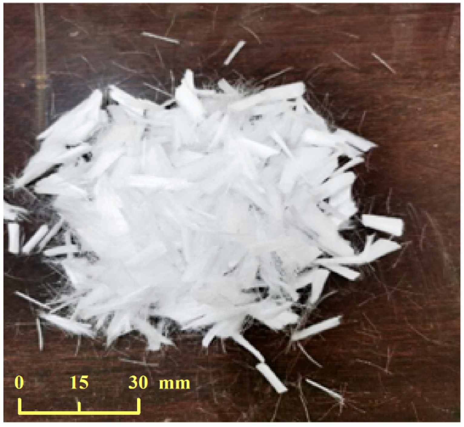
In this study, the test was performed with normal Portland cement produced by Yunnan Yiliang Southwest Cement Co., Ltd., Kunming, China, with a density of 2930 kg/m3 and a variety grade of P-O42.5. The cement with this factory number conforms to the requirements of the technical indexes in GB175-2007 “Common Portland Cement” [17]. The coarse aggregate was granite gravel with a continuous grading of 5~16 mm. The fine aggregate was quartz sand with mud content of 1.8% by mass, fineness modulus of 2.4, and excellent particle grading. The water-reducing admixture was a composite polycarboxylic acid high-efficiency water-reducing admixture. It has a water reduction rate of about 28%, excellent compatibility with cement, and meets the requirements for workable concrete. The fly ash was a high-quality grade I fly ash produced by BoRun Materials Ltd., Zhejiang, China, conforming to the provisions of GB/T1596-2017 “Fly Ash Used for Cement and Concrete” [18]. The selected steel fiber was shear-wave-type steel fiber produced by Hengshui Junye Material Co., Ltd., Hengshui, China, and the polypropylene fibers were high-strength bundled filament fibers produced by Huixiang Fiber Material Factory (see Table 1 and Table 2, Figure 1 and Figure 2). In this experiment, PC and S1PP0.2 (steel fiber 1%, polypropylene fiber 0.2%) with strength grades of C40 were used. The water-cement ratio was 0.4 and the sand ratio was 0.3. The concrete mixes were calculated according to the “Concrete Mixing Ratio Design Regulations” (JGJ55-2011) [19] (see Table 3).

2.2. Specimen Preparation

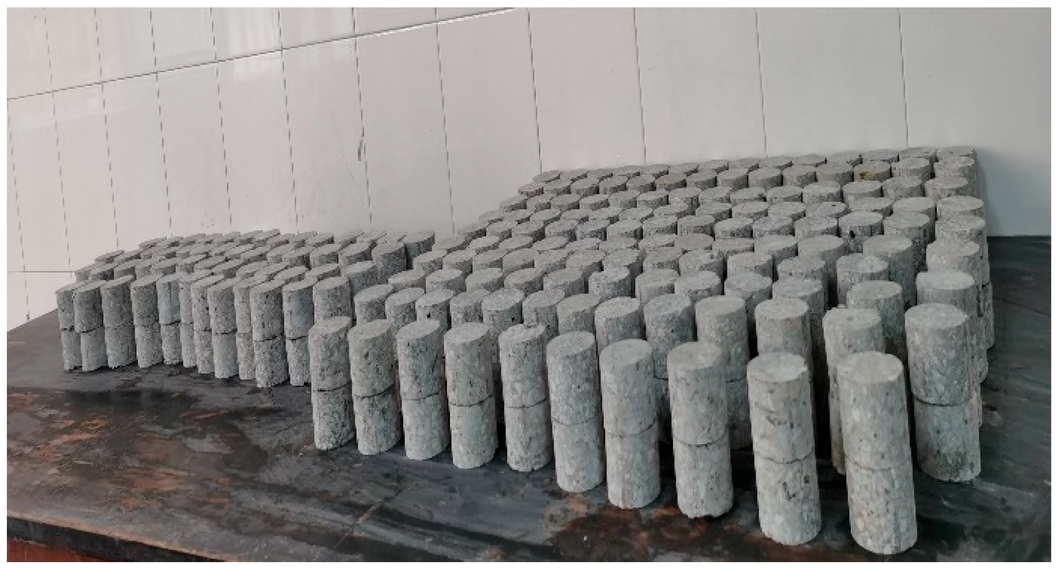
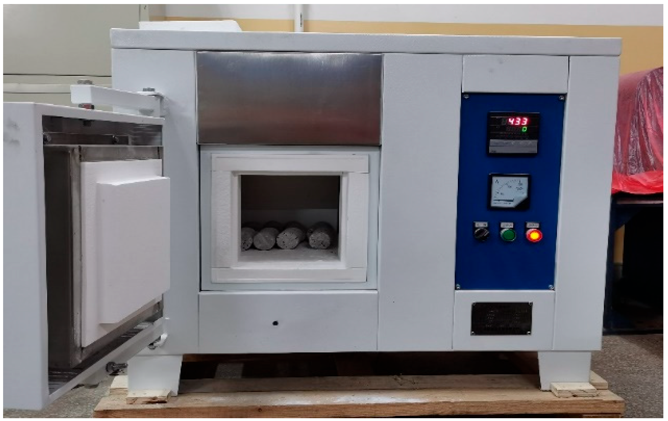
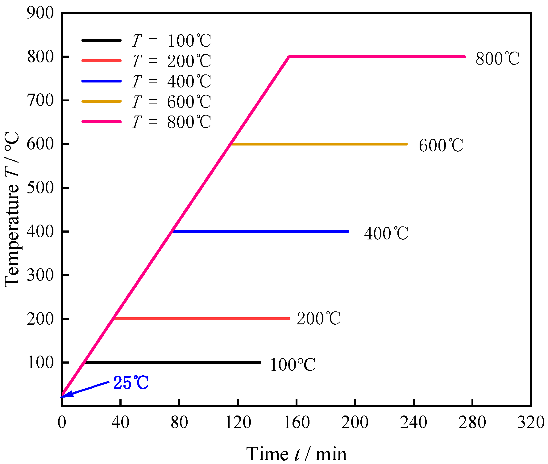
According to (CECS13:2009) [20] “FRC experimental method standard”, the fiber concrete was stirred. In order to avoid the agglomeration of hybrid fibers, the coarse and fine aggregates were mixed for 30 s, and then the cement and mineral admixtures were added for dry mixing for 30 s. Then the fibers were added in batches and stirred for 60 s. Finally, the mixture of water-reducing agent and water was added and stirred for 60 s. After mixing, the concrete was loaded into 30 mm × 30 mm × 30 mm cubic concrete molds. The pouring height was half that of the concrete mold, and the concrete was vibrated with a plug-in vibrator. The mold was then removed after 24 h of curing, and the concrete was moisturized and cured until the specified age of 28 days. After curing, the cylindrical concrete specimens with a diameter of Ø 50 mm and a height of 40 mm were prepared by coring, cutting, and polishing. The non-parallelism of the two end faces of the specimen was ensured to be less than 0.02 mm after polishing (see Figure 3). The heating of specimens in different temperature groups was performed using the KRX-17B box-type resistance furnace (see Figure 4). To ensure that the specimens were heated uniformly to achieve a predetermined temperature, the cylindrical concrete specimens were placed in one layer in parallel and upside down. A gap was left between the specimens to increase the heat area. Based on our previous findings and other previous studies [21,22], the temperature gradient of all the prepared specimens was classified into six temperature groups (25 °C, 100 °C, 200 °C, 400 °C, 600 °C, and 800 °C). Each group contained three specimens, and the average values of the test results were taken. The average heating rate of the resistance furnace is set to 5 °C/min, and the heating curve is shown in Figure 5. After heating to the target temperature, the temperature is kept constant for 2 h and then cooled to room temperature in the furnace.
The static compression test of PC and S1PP0.2 specimens after heating treatment was carried out by HUT-106, a double space electro-hydraulic servo testing machine. The automatic loading scheme was set up, the loading speed was 0.6 MPa/s, and the test was run until failure. The test data were recorded, and the average value of the three data was taken as the final test result. The test results are shown in Table 4.

2.3. Test Device and Principle

The diameter of the incident, transmission, and absorption bars is 50 mm, the density of the compression rod is 7.85 g/cm3, the elastic modulus is 210 GPa, the length of the incident and transmission bars is 2000 mm, and the length of the spindle-shaped bullet is 400 mm (see Figure 6). SHPB dynamic impact tests and dynamic splitting tests were performed using Ø 50 × 40 mm cylindrical specimens, with an optimal L/D ratio between 0.5 and 1.0. In this study, the length-diameter ratio of the cylinder is 0.8. The principle of SHPB tests was based on two fundamental assumptions (i.e., the one-dimensional assumption and the stress uniformity assumption), which were also applicable in combined dynamic and static loading tests [23]. During the loading process, two strain gauges are pasted and welded at the middle position of the incident bar and the transmission bar to measure the strain signal. The data acquisition system uses an 8-channel dynamic strain gauge to output the strain signal measured by the strain gauge as an electrical signal, and the sensitivity is 1 V/1000. The data were processed using the three-wave method to obtain the average stress (σs), average strain (εs), and average strain rate ( ε ˙ s ) of the concrete specimens, as expressed by Equations (1)–(3).
σ s = σ 1 + σ 2 2 = A 0 2 A s E ε i + ε r + ε t
ε s = 0 t ε ˙ s d t = C 0 L s 0 t ε i ε r ε t d t
ε ˙ s = v 1 v 2 L s = C 0 L s ε i ε r ε t
where ε i ε r , and ε t are the incident strain, reflection strain, and transmission strain, respectively; E , c 0 , and A 0 are the elastic modulus of the compression bar, wave velocity, and cross-sectional area, respectively; A s and L s are the cross-sectional area and length of the specimen, respectively; t is the propagation time of the impulse signal in the concrete specimen (s); σ 1 and σ 2 are the stresses of the specimen at the incident and transmission ends, respectively; and v 1 and v 2 are the mass velocities at the incident and transmitted ends of the specimen, respectively.

3. Test Scheme and Result Analysis

3.1. Stress Uniformity Verification

In order to ensure the validity of the test data, the specimen needs to meet the uniformity assumption during the impact process. Typically, the strain data obtained by the impact of a normal-temperature concrete specimen under the impact rate of 0.3 MPa are used to verify the stress balance. From Figure 7, it can be seen that the two are in good agreement and meet the stress uniformity conditions, indicating that the test data are effective.

3.2. Uniaxial Dynamic Impact Compression Test

3.2.1. Test Results

C40 plain concrete and polypropylene-steel HyFRC specimens in six temperature groups (25 °C, 100 °C, 200 °C, 400 °C, 600 °C, and 800 °C) were subjected to conventional uniaxial dynamic impact compression tests. The impact air pressure was 0.3 MPa, 0.4 MPa, and 0.5 MPa. Three sets of effective parallel tests were carried out for each group of working conditions. If the relative error between the test results is less than 5%, the data are considered to be valid. If the relative error is greater than 5%, the test is repeated. The average of the three effective experiments is taken as the final result. The experimental results of dynamic impact compression peak stress and peak strain are shown in Table 5.

3.2.2. Dynamic Peak Intensity

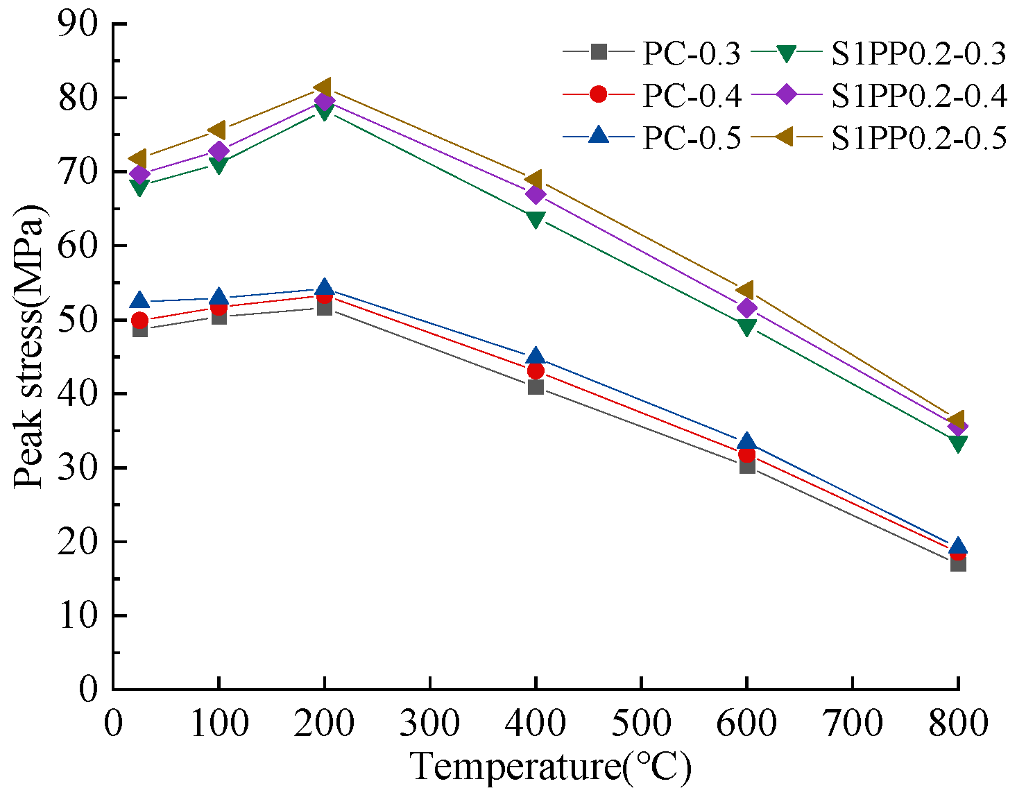
The relationship between peak stress and temperature was plotted based on the results of uniaxial dynamic compression tests at different impact air pressures (see Figure 8). Under the same impact air pressure, C40 plain concrete and HyFRC show a temperature enhancement effect within 25 °C~200 °C. With the increase in temperature, the compressive strength increases slightly. The reason is that in this temperature range, the internal microstructure of concrete will produce secondary hydration [24], and the mechanical properties will be improved. At the same time, the impact load has a compaction effect on the microcracks of the concrete material, which significantly reduces the number of primary bubbles and microcracks in the internal structure of the concrete, and the macroscopic performance is the enhancement of mechanical properties. At the temperature gradient of 200 °C~800 °C, the specimens exhibit a significant temperature damage effect, and their compressive strength decreases significantly with increasing temperature. The variation mechanism is basically consistent with static compression. However, another reason for the enhanced dynamic compressive strength is the compaction of microfractures in the concrete material by impact loading, significantly reducing the number of indigenous air bubbles and microcracks in the internal structure of the concrete. The HyFRC exhibits both positive and negative effects. The dynamic compressive strength of S1PP0.2 HyFRC at 200 °C was the greatest, with an increase of 51.7%, 49.3%, and 50.2% in dynamic compressive strength compared to C40 plain concrete at impact air pressures of 0.3 MPa, 0.4 MPa, and 0.5 MPa, respectively. At an impact air pressure of 0.3 MPa and a temperature of 800 °C, the dynamic compressive strength of S1PP0.2 HyFRC increased by 97.1% compared to C40 plain concrete.

3.2.3. Dynamic Peak Strain

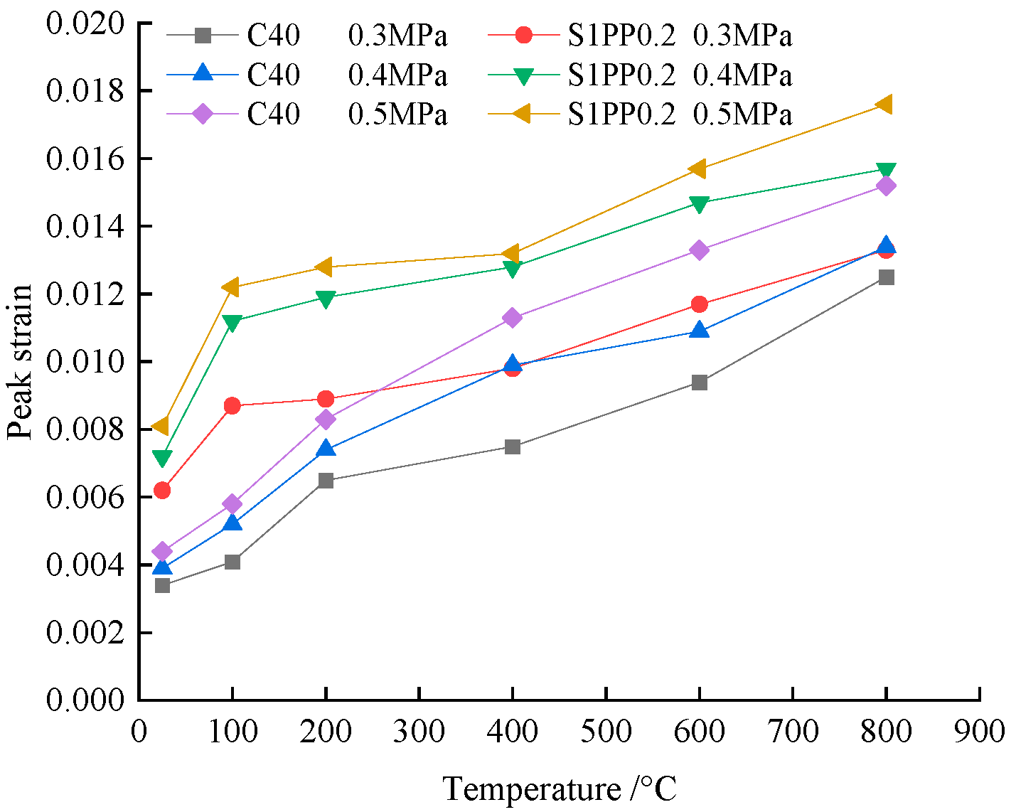
Different impact air pressures in the air chamber attribute different initial velocities to the bullets, indirectly leading to differences in the damage strain rate of concrete specimens during dynamic impact [25]. According to the peak strain results, the peak strain variation patterns of specimens in different temperature groups at different impact air pressures were explored (see Figure 9). It can be seen that the peak strain of C40 plain concrete and S1PP0.2 HyFRC increases with the increasing impact air pressure under the same temperature conditions. At the same impact air pressure, the peak strain of C40 plain concrete and S1PP0.2 HyFRC increases with the increasing temperature gradient. This result indicates that the dynamic peak strain of both C40 plain concrete and S1PP0.2 HyFRC is enhanced with increasing temperature and impact air pressure.

3.2.4. Stress-Strain Curves

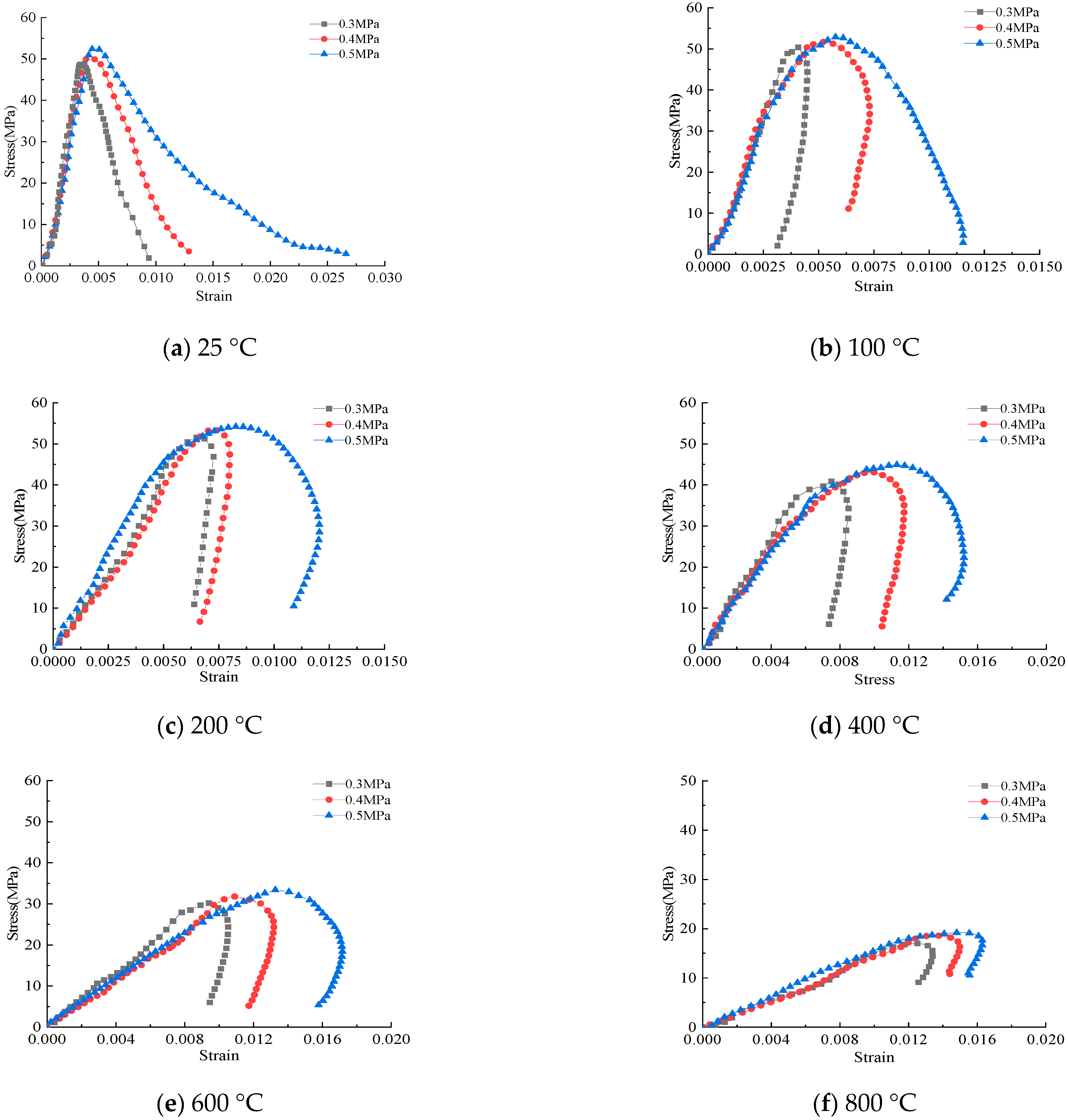
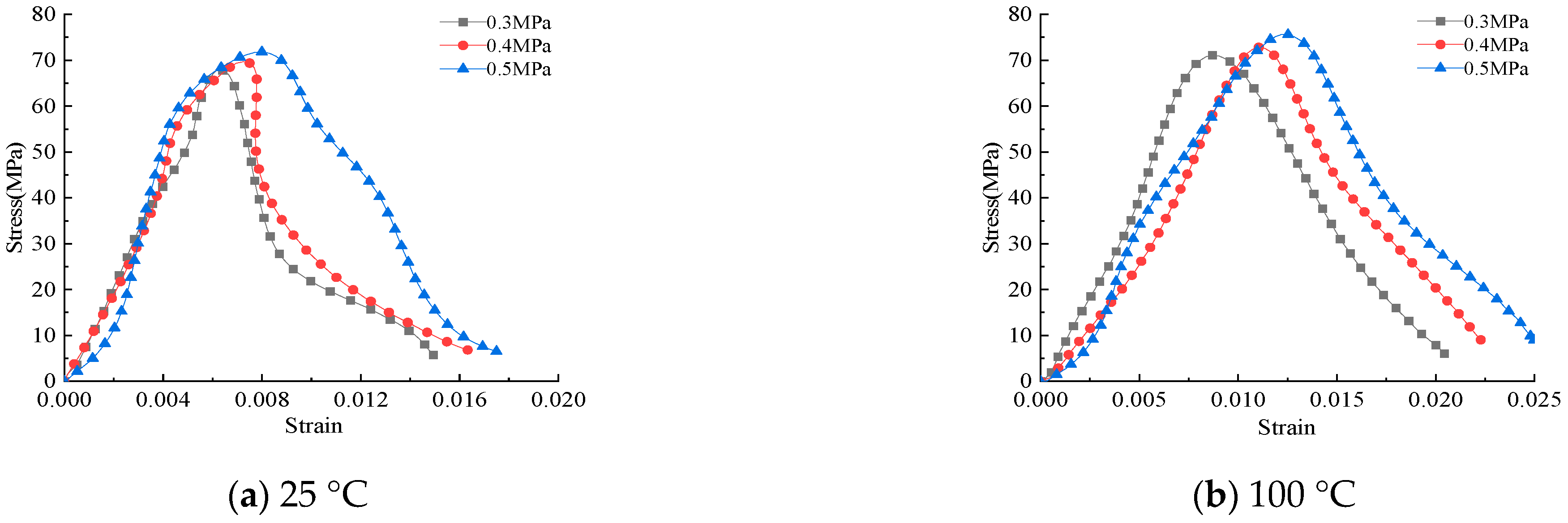
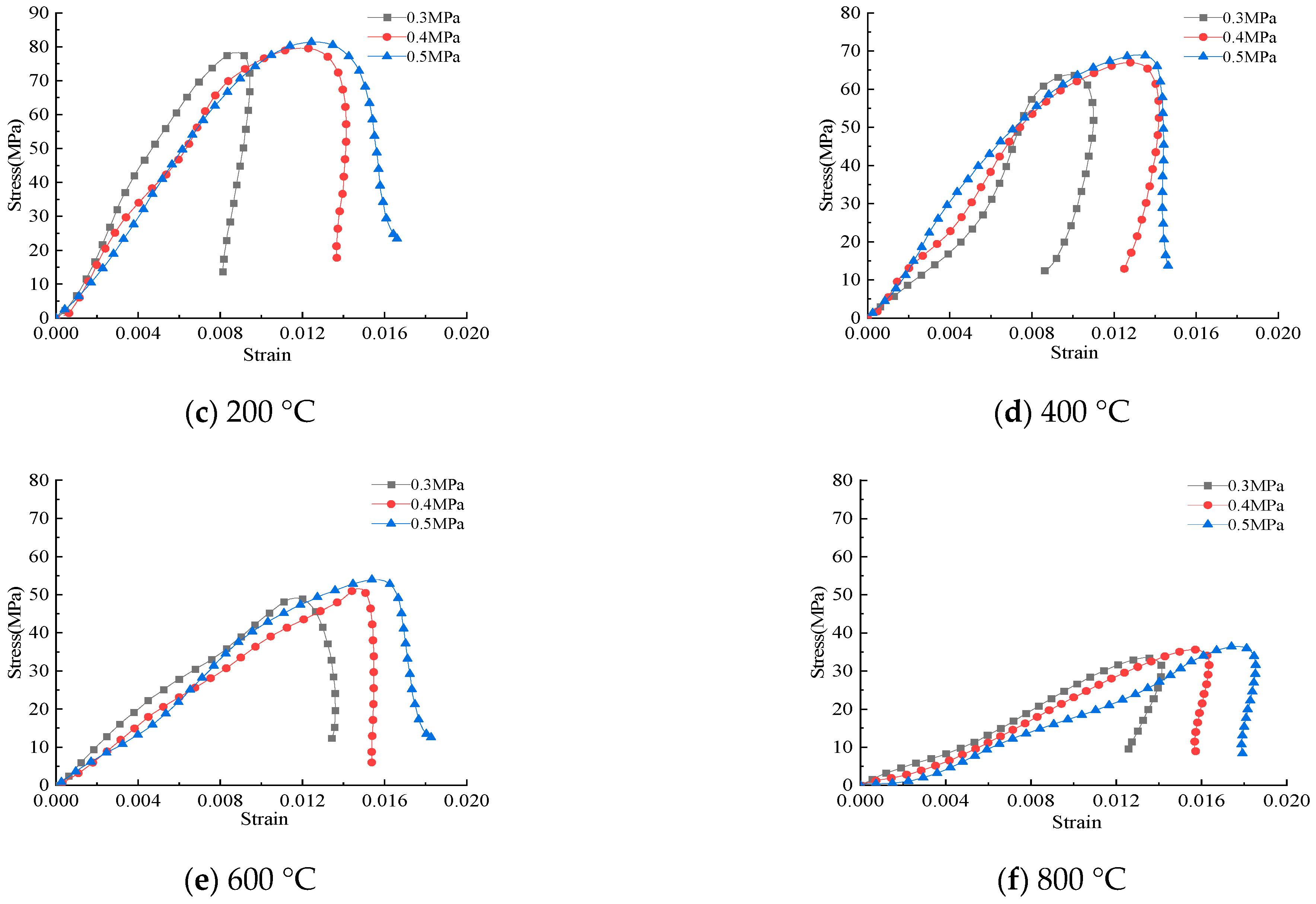
In order to more intuitively show the dynamic strength and mechanical properties of C40 plain concrete and optimally mixed S1PP0.2 HyFRC, the SHPB processing software was used to plot the stress-strain curve according to the test results (see Figure 10 and Figure 11). By comparing the stress-strain curves of C40 plain concrete and S1PP0.2 HyFRC in the six temperature groups (25 °C, 100 °C, 200 °C, 400 °C, 600 °C, and 800 °C), it can be observed that with the increase in the impact air pressure, the peak stress and peak strain of the concrete in the same temperature group gradually increase, demonstrating the reinforcing effect of the impact air pressure. At the same impact rate, the dynamic stress-strain curves of C40 plain concrete and S1PP0.2 HyFRC in the same temperature group are relatively similar. The change rule of the stress-strain curve of the specimen after temperature treatment is obviously different from that of the normal temperature specimen, and the higher the temperature is, the more significant the difference is. With the increase in the temperature gradient, the plastic stage of the curve continues to extend, showing plastic damage characteristics, and the peak stress continues to decline. The macroscopic performance shows that the mechanical properties of concrete specimens continue to decrease, and the degree of damage continues to increase. On the other hand, the effect of high temperature enhances the plastic deformation capacity of concrete upon damage, and the HyFRC exhibits a more significant enhancement in its ductility. It can also be observed from the figure that the stress-strain curve shows the phenomenon of maximum ultimate strain rebound, i.e., the maximum ultimate strain gradually converges with the peak strain. The reason for this phenomenon is that after the dynamic load compacts, the microcracks in the concrete material during the dynamic impact test, recovery rebound occurs under the action of inertia as the dynamic impact load decreases [26].

3.2.5. Analysis of Failure Modes

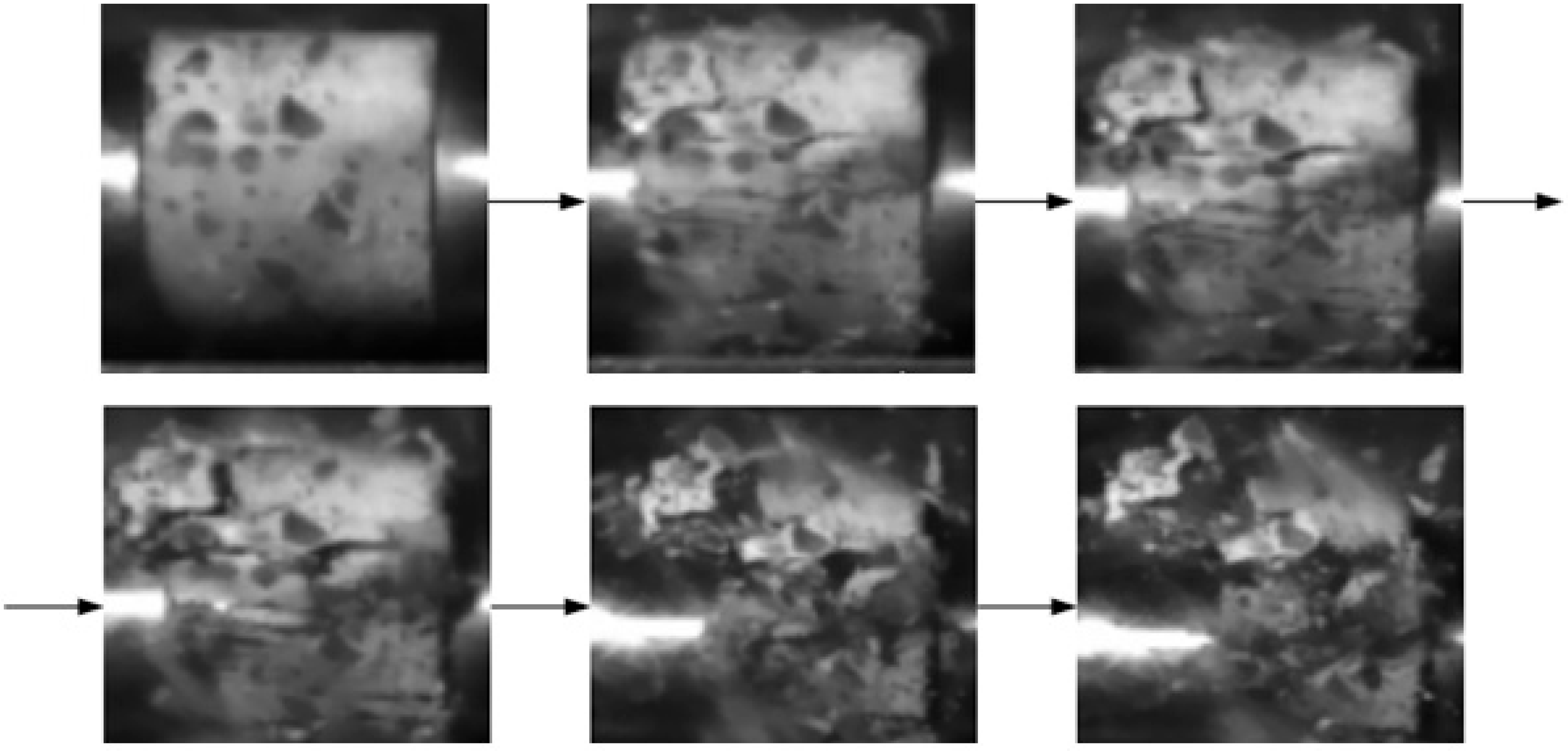
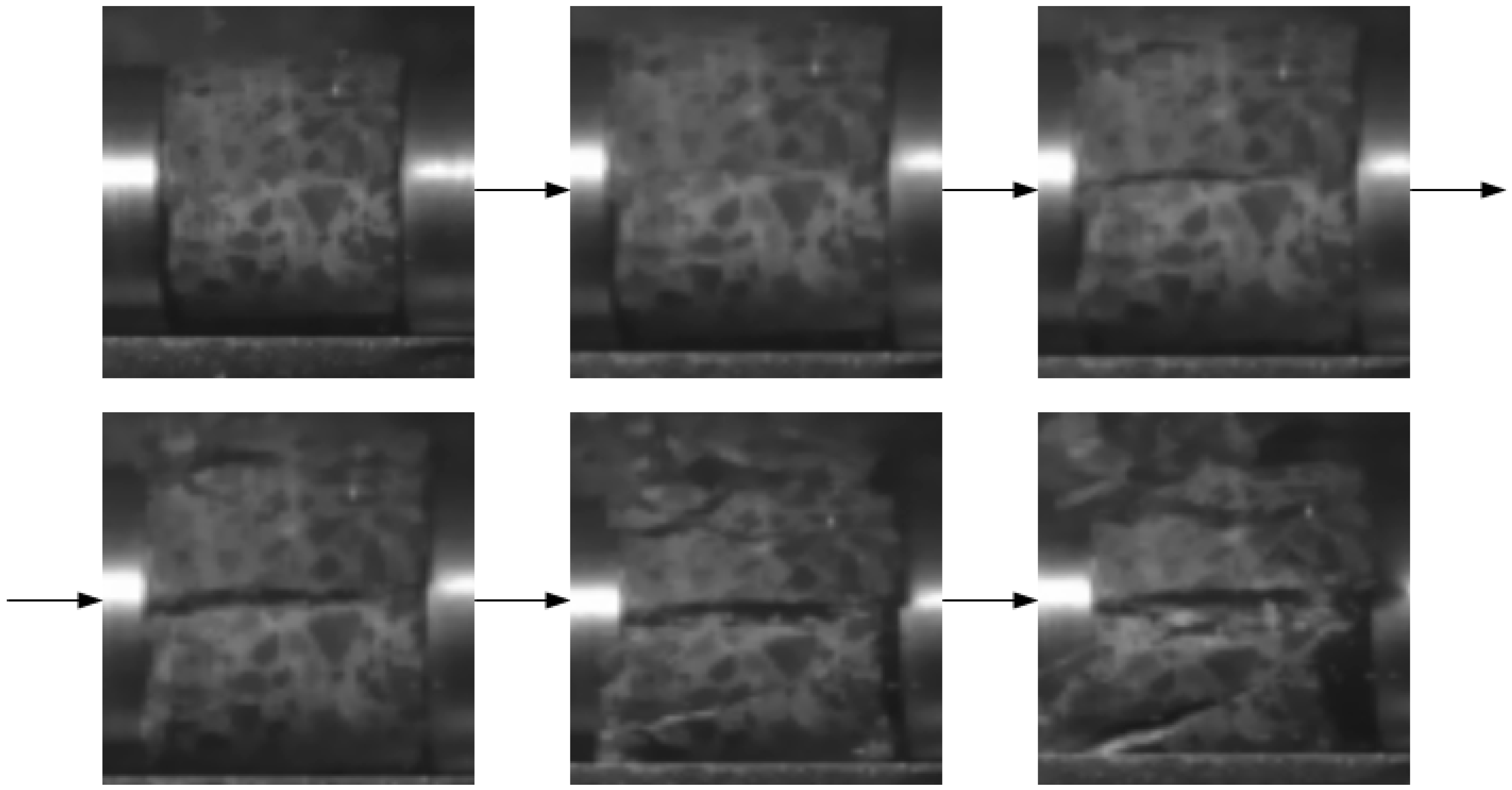
In order to study the effect of temperature on the macroscopic damage of concrete materials in dynamic impact compression tests, uniaxial dynamic impact compression tests of regular C40 plain concrete and S1PP0.2 HyFRC in different temperature groups were conducted, and the macroscopic failure modes were comparatively investigated. The failure modes of C40 plain concrete and S1PP0.2 HyFRC in six temperature groups (25 °C, 100 °C, 200 °C, 400 °C, 600 °C, and 800 °C) at an impact air pressure of 0.3 MPa is shown in Figure 12 and Figure 13.
In general, both C40 plain concrete and S1PP0.2 HyFRC in all six temperature groups become severely damaged with increasing temperature. At 25 °C and 100 °C, the failure mode of C40 plain concrete is surface spalling; at 200 °C and 400 °C, the failure mode is mainly core failure; at 600 °C and 800 °C, the failure mode develops into mass fragmentation and crushing. S1PP0.2 HyFRC exhibits no significant failure at 25 °C and 100 °C, with only small cracks observed; the failure mode at temperatures of 200 °C and 400 °C is surface spalling, exhibiting unpropagated cracks under the action of hybrid fibers; at 600 °C and 800 °C, the failure mode is dominated by the core failure, and the steel fibers passing through the body of the concrete as well as those pulled out during the core failure process can be clearly observed. Under the same impact air pressure and the same temperature condition, S1PP0.2 HyFRC is less damaged and more resistant to impact compression than C40 plain concrete [27].

3.3. Analysis of High-Speed Camera Results

The entire process of uniaxial dynamic impact compression and uniaxial dynamic impact splitting tests of the specimens was filmed using an Y7S2MotionPro high-speed camera (see Figure 14). It can more intuitively and dynamically reproduce the deformation and damage characteristics of concrete specimens under dynamic impact compression and splitting and compensate for the inability to visualize the development of specimen cracks in the case of rapid impact and a high-strain rate [28,29,30,31]. In order to highlight the advantages of the high-speed camera, a maximum impact rate of 0.5 MPa was adopted to record the damage process of C40 plain concrete and S1PP0.2 HyFRC under uniaxial dynamic impact compression and uniaxial dynamic impact splitting at 25 °C (see Figure 15 and Figure 16). In order to compare the damage process at the same moment, one photo was selected at an interval of six photos, and a total of six photos were selected to reproduce the whole destruction process. The direction of the arrows in the Figure 15 and Figure 16 indicates the sequence of the damage process.
The comparison of photos in Figure 15 and Figure 16 reveals a significant difference in the damage patterns of C40 plain concrete and S1PP0.2 HyFRC under uniaxial dynamic impact compression. Since the dynamic tensile capacity of concrete is much smaller than the dynamic compressive capacity, C40 plain concrete is first damaged by spalling along the axial surfaces, followed by core failure. Under the action of the impact compression stress wave, the specimen presents fragmentation failure and crushing failure. S1PP0.2 HyFRC improved the toughness of concrete, leading to significantly different failure modes from C40 plain concrete. The S1PP0.2 HyFRC exhibits splitting and tensile damage along the axial direction, dominated by progressive surface spalling and core failure.

4. Numerical Simulation

4.1. Establishment of the SHPB Finite Element Model

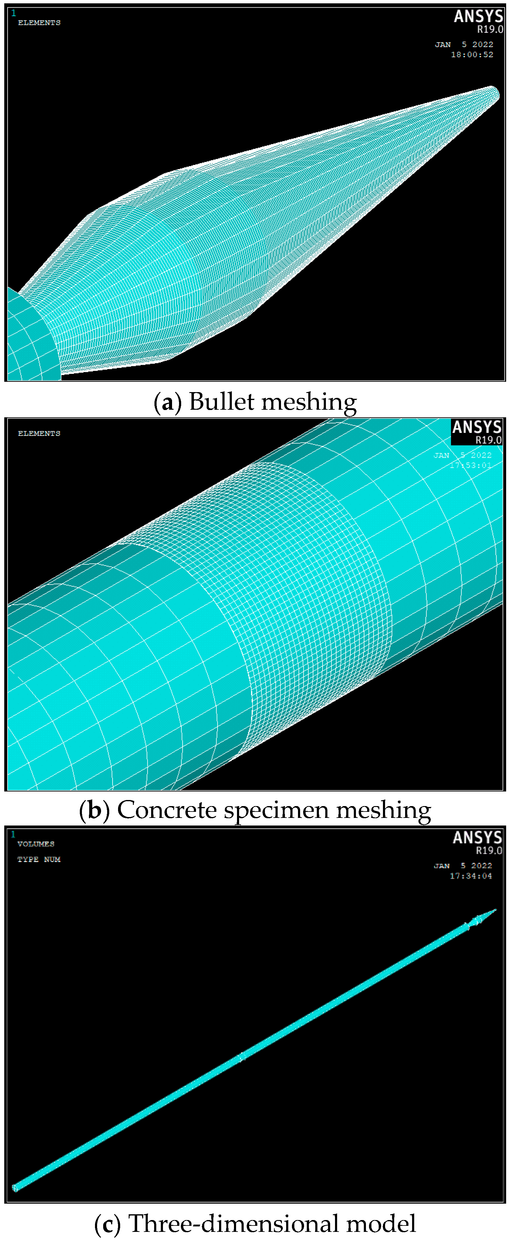
Considering the limitations of the test, it can only obtain the macroscopic mechanical properties of the test and cannot further study the stress propagation law of the specimen under impact load. That is, the finite element software ANSYS/LS-DYNA is used to carry out SHPB numerical simulation, and the simulation results and experimental results are compared and analyzed, so as to achieve the purpose of mutual verification. The model is mainly composed of four parts: the concrete specimen, incident bar, transmission bar, and bullet. The eight-node hexahedron Solid164 volume element is selected. The bullet, incident bar, and transmission bar were made of linear elastic steel material with a length of 2 m, a radius of 0.025 m, a modulus of elasticity of 211 GPa, and a density of 7850 kg/m3. The incident bar, transmission bar, and specimen were all meshed hexahedrally using the mapping method, the contact of the specimen with the compression bar was encrypted with an 8-quantile mesh, and the specimen was meshed with a 30-quantile mesh. The spindle-shaped bullet was divided into hexahedral meshes using the sweeping method, with eight equal encryptions on the two end faces and the middle circular portion. The contact between the spindle-shaped bullet and the incident bar was defined as automatic end-face contact, and the contact between the specimen and the incident and transmission bars was defined as erosional end-face contact. A penalty function algorithm was adopted as the contact algorithm to effectively control and reduce the hourglass effect. Numerical simulation of the uniaxial dynamic impact compression and splitting tests of C40 concrete and S1PP0.2 HyFRC were performed (see Figure 17).

4.2. Determination of Concrete Material Parameters

The HJC constitutive model is suitable for studying the dynamic mechanical properties of concrete, allowing for accurate characterization of changes in the mechanical properties of concrete under the dynamic impact [32,33,34,35]. It mainly consists of a yield surface equation, a damage evolution equation, and a state equation.
(1)
Yield surface equation
The yield surface equation for the HJC constitutive model can be expressed by Equation (4):
σ * = A 1 D + B P * N 1 + C ln ε ˙ *
where A is the normalized viscous strength; B is the normalized pressure hardening coefficient; C is the influence coefficient of strain rate; N is the pressure hardening coefficient. D is the damage factor; σ * and P * are the normalized equivalent stress and hydrostatic pressure obtained by dividing the actual equivalent stress and the true hydrostatic pressure of the unit by the static compressive strength, respectively; and ε ˙ * is the normalized true strain rate obtained by dividing the true strain rate ε ˙ by the reference strain rate ε ˙ 0 .
(2)
Damage evolution equation
The damage evolution equation in the HJC model characterizes the damage based on the equivalent plastic strain and the plastic volume strain accumulation, which can be expressed by Equation (5):
D = ε p + u p D 1 P * + T * D 2
where D is the damage factor; D 1 and D 2 are the damage coefficients; ε p and u p are the equivalent plastic strains and the corresponding volumetric strains, respectively; and T * is the normalized maximum tensile stress obtained by dividing the maximum tensile strength by the static compressive strength.
(3)
State equation
The state equation describes the relationship between hydrostatic pressure P and volumetric strain μ (see Figure 18). The variation can be divided into three stages.
The first stage (O to A) is the linear elastic stage ( P < P c ). When the pressure is less than or equal to P c , it satisfies the Equation (6), where K is the bulk modulus.
P = K μ
The second stage (A to B) is the compaction transition stage ( P c P P l ). When the pressure is greater than or equal to P c or less than or equal to P l , the concrete material is compacted and produces a plastic volumetric strain, which can be expressed by Equation (7):
P = P l P c μ μ c μ l μ c + P c
The third stage (B to C) is the failure stage ( P > P l ). When the pressure is greater than P l , the concrete is completely crushed and damaged, satisfying Equations (8) and (9):
P = K 1 μ ¯ + K 2 μ ¯ 2 + K 3 μ ¯ 3
μ ¯ = μ μ l 1 + μ l
where P c and μ c are the crushing pressure and volumetric strain; P l and μ l are the locking pressure and locking volumetric strain, respectively; K 1 , K 2 and K 3 are the pressure parameters; and μ ¯ is the corrected volumetric strain.
The HJC constitutive model consists of 21 parameters, and all of them can be determined by tests or computational equations, except for normalized viscous strength A, normalized pressure hardening coefficient B, strain rate influence coefficient C, and pressure hardening coefficient N. Parameters such as density ρ and static uniaxial compressive strength f c can be accurately obtained from the tests, and some of the parameters can be calculated from Equations (10)–(12):
G = E 2 1 + ν
P c = f c 3
T = 0.62 f c 1 2
where G and E are shear modulus and elastic modulus, respectively; v is Poisson’s ratio; and T is static tensile strength.
The remaining parameters are less sensitive to the strength of the concrete material, and their values are determined according to the relevant literature [36,37,38]. Based on the test data of C40 plain concrete and S1PP0.2 HyFRC at 800 °C and an impact air pressure of 0.3 MPa, the values of the A, B, C, and N parameters were corrected by repeated calculations after substituting them into the constitutive model. It is worth mentioning that because there is no change in heat during the impact compression test of heated concrete, the damage caused by temperature to concrete specimens is macroscopically manifested in the deterioration of the physical and mechanical properties of concrete materials, which can be characterized by the change in material model parameters [39]. The basic mechanical parameters of the specimens at room temperature and after heating were obtained by static experiments. In this way, the numerical simulation results derived from the modified parameters of the HJC constitutive model can more accurately reflect the test results (see Table 6 and Table 7).

4.3. Numerical Simulation Results

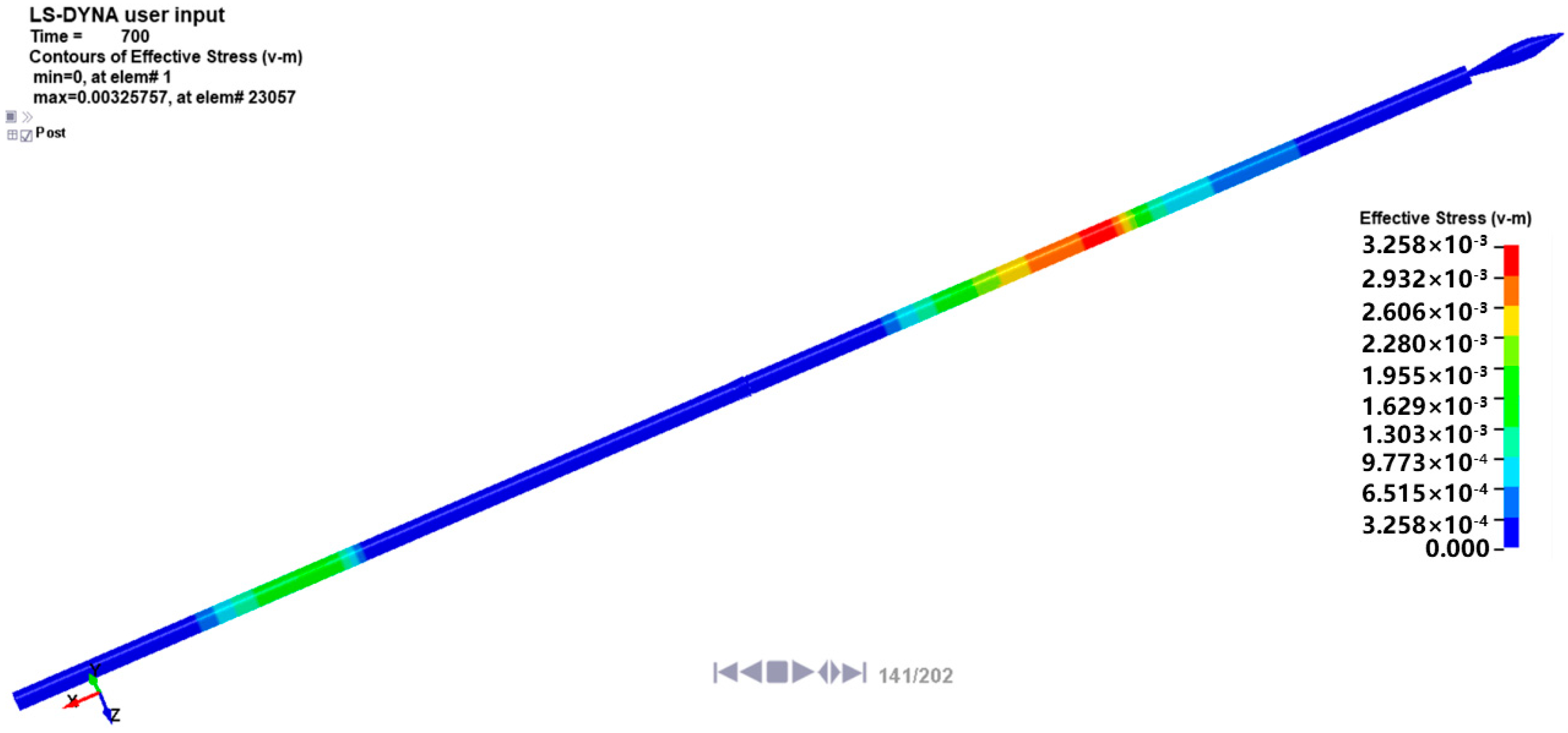
The d3plot result file derived from the LS-DYNA Solver was imported into the LS-PrePost software 19.0 to examine the numerical simulation results (see Figure 19 and Figure 20). Firstly, the spindle-shaped bullet impacts the incident bar to produce an incident stress wave. After the incident stress wave arrives at the specimen position, reflection and transmission occur at the specimen interface, resulting in the reflected stress wave and the transmitted stress wave.
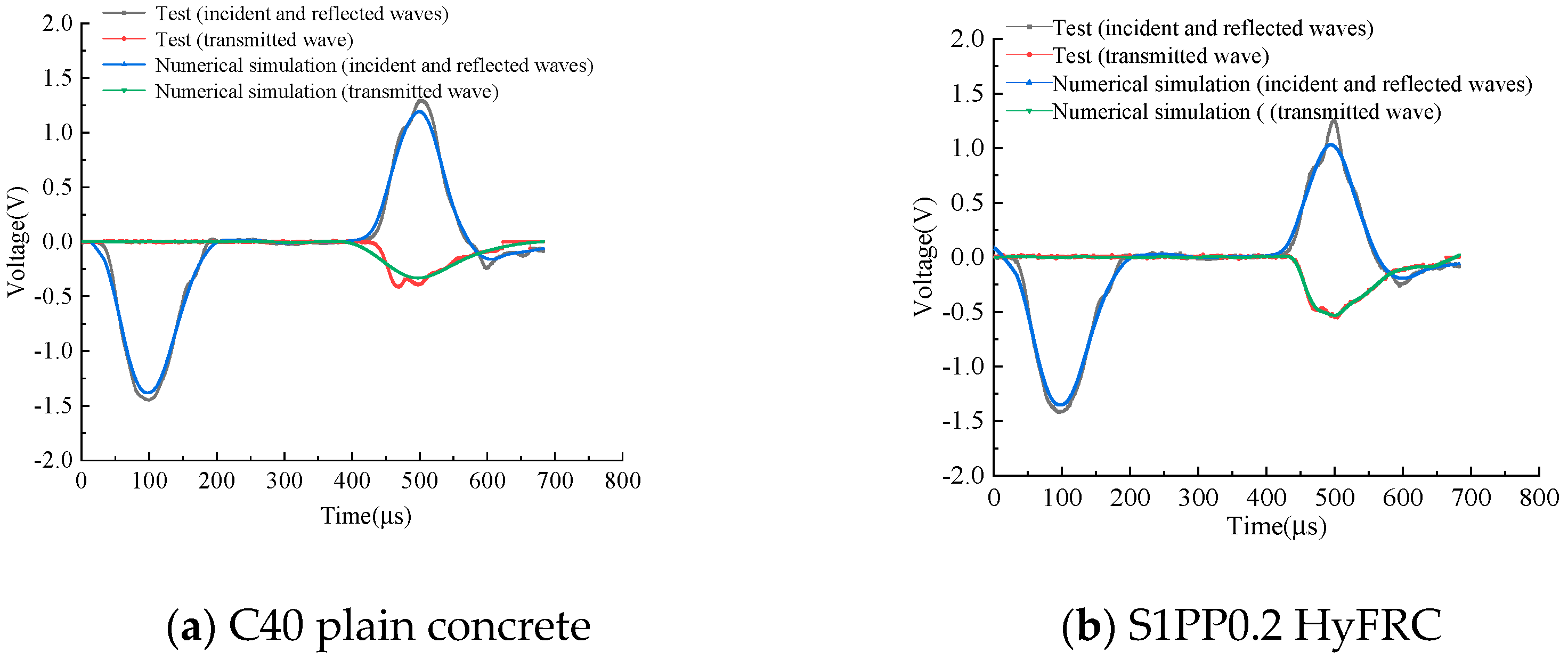
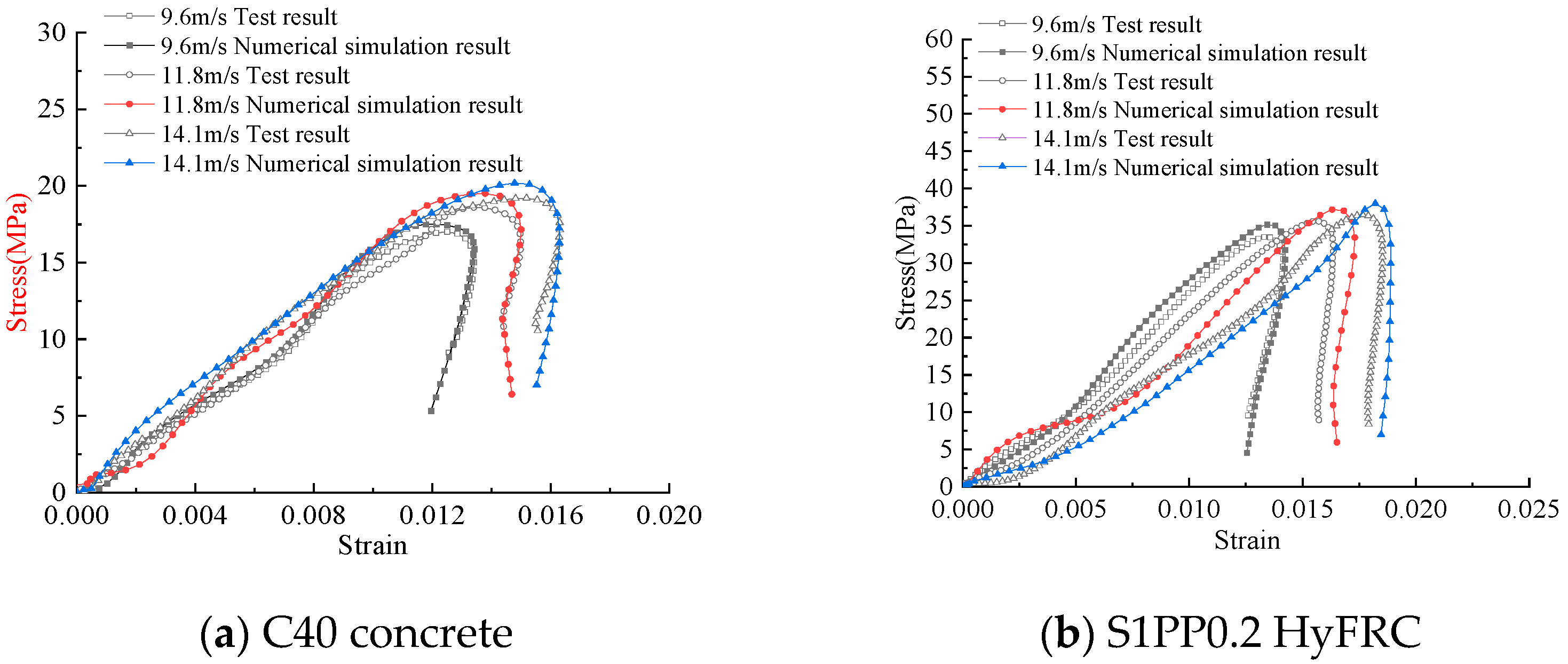
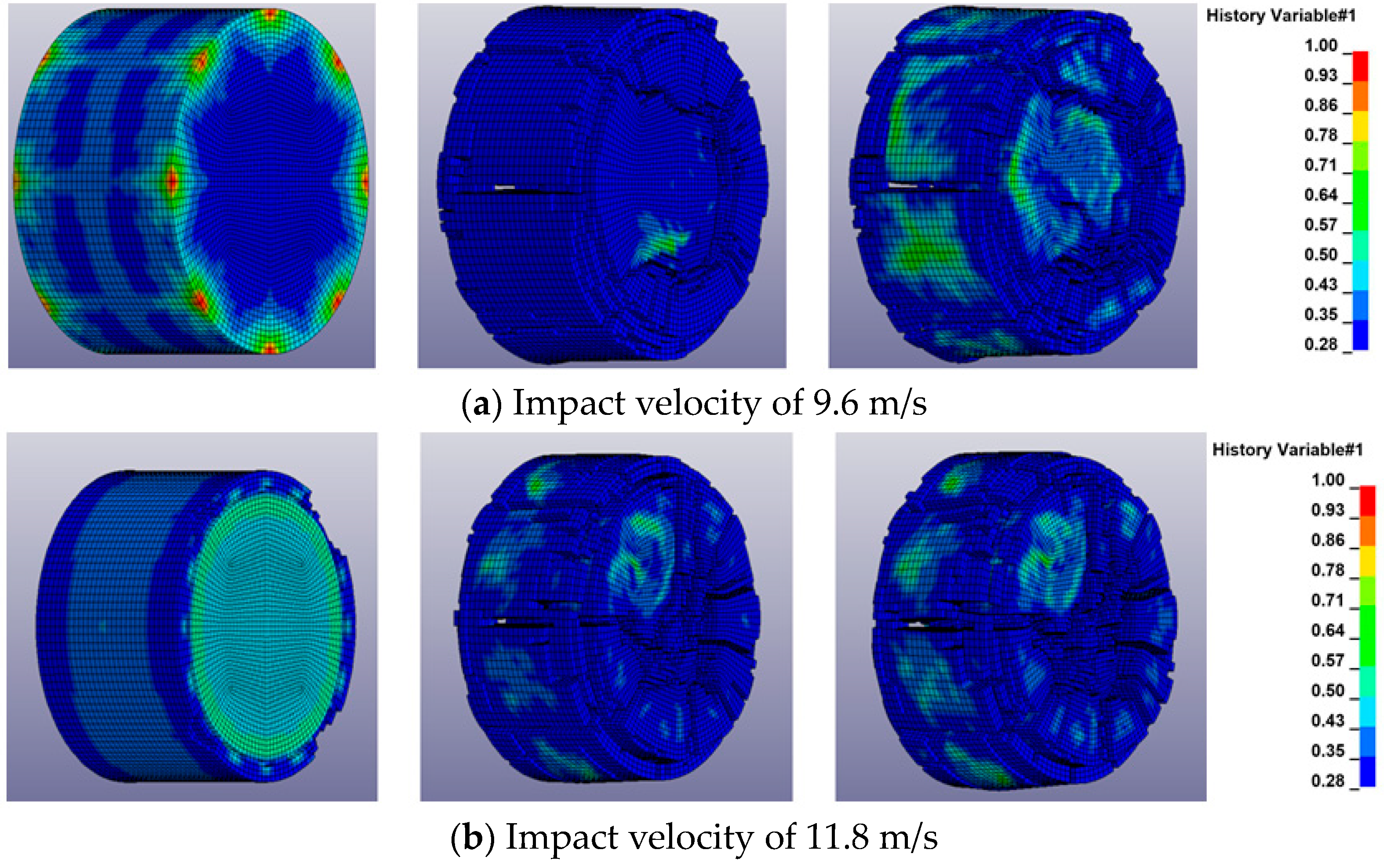
The velocities measured by the velocimetry system under 0.3 MPa, 0.4 MPa, and 0.5 MPa air pressure are 9.6 m/s, 11.8 m/s, and 14.1 m/s, respectively. The measured bullet velocities in the test were consistent with the bullet velocity settings in the numerical simulation. The modified waveforms and the comparisons of stress-strain curves can be seen to be in very good agreement (see Figure 21 and Figure 22).
The modified HJC model accurately reflects the mechanical properties of C40 plain concrete and S1PP0.2 HyFRC. Numerical simulations considering the homogeneity of the specimens and the reference values taken for the parameters of the modified HJC model introduce errors. However, the errors of numerical simulation and test results are small, and the error range of peak stress and peak strain at different impact velocities is within 6% (see Table 8).
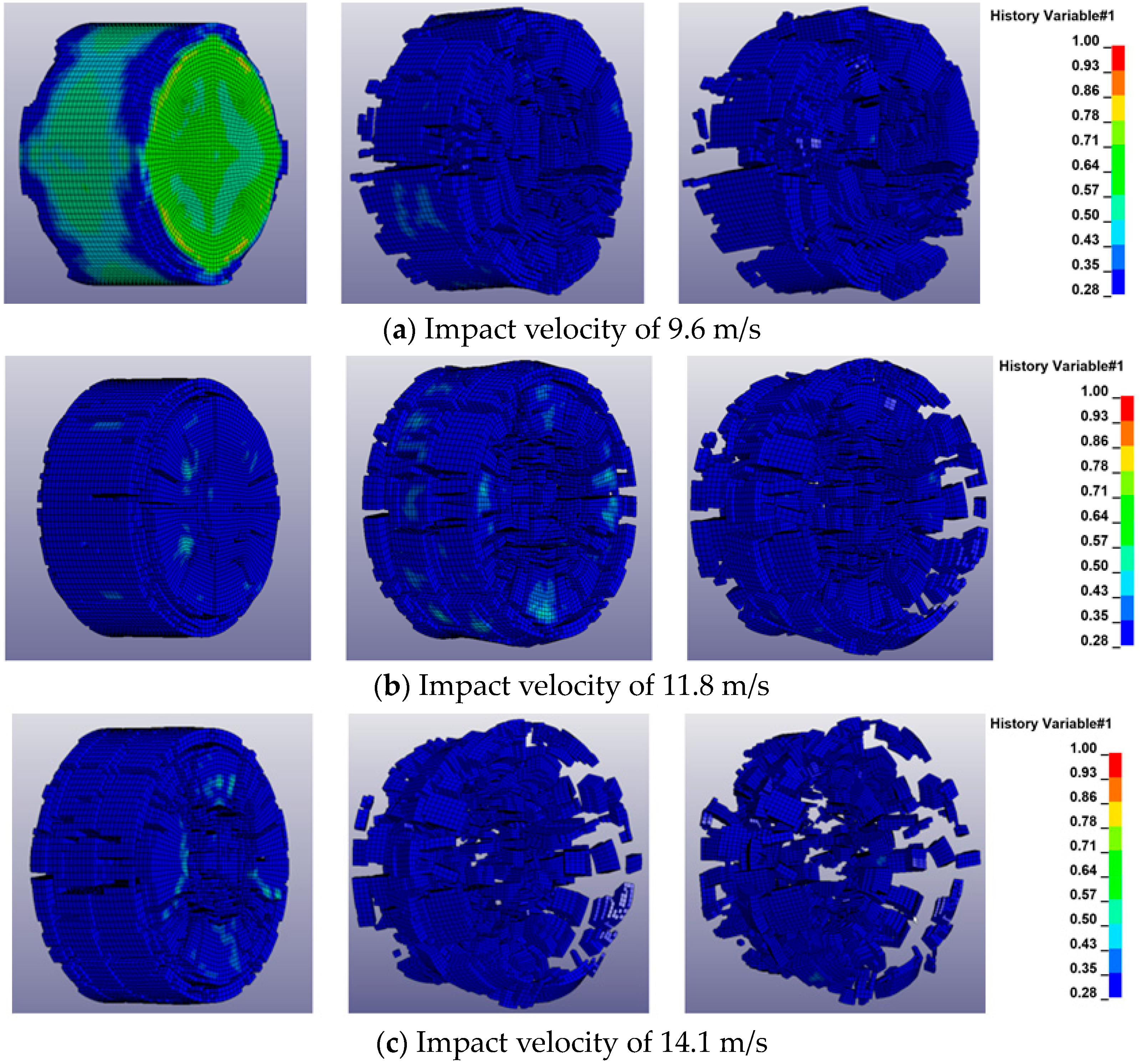
The failure modes of C40 plain concrete and S1PP0.2 HyFRC in the 800 °C temperature group at impact velocities of 9.6 m/s, 11.8 m/s, and 14.1 m/s were analyzed by numerical simulation (see Figure 23 and Figure 24). The comparison reveals that the numerical simulation results are consistent with the failure modes obtained from practical tests. The failure processes of C40 plain concrete and HyFRC under the same impact air pressure are firstly from the outer surface and then gradually extend to the middle of the specimen. At a certain level of failure, large crack damage occurs, and the failure mode of the concrete specimen changes from gradual damage to rapid damage. The damage mechanism of concrete under dynamic impact compression loading can be explained based on the stress wave. Since the end faces of the concrete specimen are in contact with the incident and transmissive bars, the tensile stress wave—formed after the impact compression wave arrives at the end faces of the specimen—results in tensile damage to the concrete specimen [40]. The damage degree of the same concrete specimen at the same moment increases significantly with increasing impact rate. Moreover, compared to C40 plain concrete, S1PP0.2 HyFRC exhibits a significant improvement in the damage degree and a significant reduction in the number of fragments at the same impact rate. The failure mode changes from the crushing failure of C40 plain concrete to core failure. Numerical simulation also reflects that HyFRC significantly improves the mechanical properties of concrete and enhances its resistance to dynamic impact compression.

5. Conclusions

(1) Both C40 and S1PP0.2 HyFRC have temperature enhancement effects at temperatures ranging from 25 °C to 200 °C. The peak strength of the sample is the highest at 200 °C, and the peak strength of the sample also increases significantly with the increase in impact pressure. When the temperature gradient exceeds 200 °C, both types of concrete experience temperature damage effects. In addition, both C40 plain concrete and S1PP0.2 HyFRC exhibit enhanced dynamic peak strain effects with increasing temperature and impact air pressure.
(2) With the increase in temperature, the damage forms of C40 plain concrete and S1PP0.2 HyFRC are different in the uniaxial dynamic impact test, and the damage degree becomes more and more prominent. At 25 °C and 100 °C, the failure mode of C40 plain concrete is surface spalling; at 200 °C and 400 °C, the failure mode is mainly core failure; and at 600 °C and 800 °C, the failure mode develops into mass fragmentation and crushing. In contrast, S1PP0.2 HyFRC shows no obvious damage at 25 °C and 100 °C; at 200 °C and 400 °C, its failure mode is surface spalling; and at 600 °C and 800 °C, its failure mode is dominated by core failure. Hybrid fiber concrete has an obvious reinforcement effect.
(3) Uniaxial dynamic impact compression tests are simulated using modified constitutive model parameters for C40 concrete and HyFRC. The obtained impact waveforms and stress-strain curves are consistent with the test results, with the comparison error between peak stress and peak strain effectively controlled within 6%. The HJC constitutive model is suitable for studying the dynamic mechanical properties of concrete, allowing for accurate characterization of changes in the mechanical properties of concrete under the dynamic impact.

Author Contributions

Conceptualization, J.D. and X.S.; methodology, X.L., X.S. and L.L.; validation, X.L., L.L. and X.C.; resources, J.D.; data curation, L.L.; writing—original draft preparation, X.S., X.L. and L.L.; writing—review and editing, X.C., X.L. and L.L.; supervision, J.D.; project administration, J.D.; funding acquisition, X.S. All authors have read and agreed to the published version of the manuscript.

Funding

This work is supported by the Special Basic Cooperative Research Programs of the Yunnan Provincial Undergraduate University’s Association (202301BA070001-012, 202101BA070001-137).

Data Availability Statement

The original contributions presented in this study are included in this article, and further inquiries can be directed to the corresponding author.

Conflicts of Interest

The authors declare that this research was conducted in the absence of any commercial or financial relationships that could be construed as a potential conflicts of interest.

References

  1. Tan, X.; Shen, A.Q.; Guo, Y.C. Experimental study on road performance of basalt fiber reinforced bitumen mastics. J. Build. Mater. 2016, 19, 659–664. [Google Scholar]
  2. Xin, M.; Wang, X.Z.; Dong, H. Summary of research on durability of fiber concrete. J. Liaoning Univ. Technol. (Nat. Sci. Ed.) 2020, 40, 35–39. [Google Scholar]
  3. Kumari, G.J.; Ojarestaghi, S.S.M.; Bhojaraju, C. Influence of thermal cycles and high-temperature exposures on the residual strength of hybrid steel/glass fiber-reinforced self-consolidating concrete. Structures 2023, 55, 1532–1541. [Google Scholar] [CrossRef]
  4. Jiang, X.G. Research on the durability of basalt fiber reinforced concrete. Anhui Archit. 2021, 28, 117–118. [Google Scholar]
  5. Peng, S.; Li, L.; Wu, J.; Jiang, X.Q.; Du, X.L. lmpact tests on dynamic compressive behaviors of steel fiber reinforced concrete at elevated temperature. Vib. Shock 2019, 38, 149–154. [Google Scholar]
  6. Wang, L. Experimental Study on the Mechanical Properties and Damage Evolution of Basalt Fiber Reinforced Concrete after High Temperature. Master’s Thesis, Inner Mongolia University of Technology, Huhehaote, China, 2017. [Google Scholar]
  7. Hou, L.N.; He, M.D.; Huang, W.; Zhou, X.F. Research status and prospect of mechanical properties of fiber-reinforced recycled concrete. J. Xi’an Univ. Technol. 2021, 37, 403–413. [Google Scholar]
  8. Zhao, L.P. Mechanical Behavior and Calculation Methods of Fiber & Nanosized Materials Reinforced Concrete at High Temperature. Ph.D. Thesis, Zhengzhou University, Zhengzhou, China, 2017. [Google Scholar]
  9. Zhao, Y.R.; Liu, D.K.; Wang, L.; Liu, F.F. Experimental study on mechanical properties of basalt fiber concrete after high temperature. Concrete 2019, 20, 72–75. [Google Scholar]
  10. Jiang, W.; Jiang, J.S.; Teng, C.L. Research status of hybrid fiber reinforced concrete. Build. Mater. Dev. Orientat. 2019, 17, 13–16. [Google Scholar] [CrossRef]
  11. Liu, X.; Liang, D.Y.; Luo, J.J.; Tang, Y.Q.; Wang, T.Q. Experimental study on compressive strength of steel fiber reinforced concrete at high temperature. Concrete 2018, 1, 31–34. [Google Scholar]
  12. Yang, J. Experimental Research on Mechanical Properties, Explosive Spalling Behavior and Its Improvements of Ultra-High-Performance Concrete with Coarse Aggregate Exposed to High Temperature. Ph.D. Thesis, Beijing Jiaotong University, Beijing, China, 2017. [Google Scholar]
  13. Huang, J.S. Research of the Properties of Polyvinyl Alcohol Fiber Concrete. Master’s Thesis, Yangzhou University, Yangzhou, China, 2018. [Google Scholar]
  14. Varona, B.; Baeza, J.; Bru, D. Influence of high temperature on the mechanical properties of hybrid fibre reinforced normal and high strength concrete. Constr. Build. Mater. 2018, 159, 73–82. [Google Scholar] [CrossRef]
  15. Kodur, V.; Khaliq, W. Effect of temperature on thermal properties of different types of high-strength concrete. J. Mater. Civ. Eng. 2011, 23, 793–801. [Google Scholar] [CrossRef]
  16. Sanchayan, S.; Foster, S.J. High temperature behaviour of hybrid steel-PVA fibre reinforced reactive powder concrete. Mater. Struct. 2016, 49, 769–782. [Google Scholar] [CrossRef]
  17. GB175-2007; Common Portland Cement. Standards Press of China: Beijing, China, 2007.
  18. GB/T1596-2017; Fly Ash Used for Cement and Concrete. Standards Press of China: Beijing, China, 2017.
  19. JGJ5 5-2011; Concrete Mixing Ratio Design Regulations. China Building Industry Press: Beijing, China, 2011.
  20. CECS13:2009; FRC Experimental Method Standard. China Plan Publishing House: Beijing, China, 2009.
  21. Li, T.; Zhang, X.G.; Liu, H.X.; Fang, J.Z.; Chen, C. Experimental research on mechanical properties of hybrid fiber concrete after high temperature. J. Railw. Sci. Eng. 2020, 17, 1171–1177. [Google Scholar]
  22. Liu, Y.W.; Liu, L.; Meng, X. Study on the mechanical properties of basalt fiber concrete under different temperature and with different dosage. Chem. Miner. Process. 2022, 51, 26–31. [Google Scholar]
  23. Gong, F.Q. Experimental Study of Rock Mechanical Properties under Coupled Static-Dynamic Loads and Dynamic Strength Criterion. Ph.D. Thesis, Central South University, Changsha, China, 2010. [Google Scholar]
  24. Mao, Z.H.; Zhang, J.C.; Li, Y.Q.; Du, G.F.; Yang, X. Performance Degradation and Microscopic Structure of Reactive Powder Concrete after Exposure to High Temperature. J. Build. Mater. 2020, 25, 1225–1232. [Google Scholar]
  25. Ni, X. Effect of Polypropylene Fiber on Mechanical Properties of Concrete under Cyclic Loading. Master’s Thesis, Anhui University of Science and Technology, Huainan, China, 2021. [Google Scholar]
  26. Xu, J.Y.; Zhao, D.H.; Fan, F.L. Dynamic Characteristics of Fiber Reinforced Concrete; Northwest University of Technology Press: Xi’an, China, 2013. [Google Scholar]
  27. Luo, H.L.; Yang, D.Y.; Zhou, X.Y.; Shan, C.C.; Liu, X.; Zhao, F.L. Mechanical properties of polypropylene fiber reinforced concrete with different aspect ratios. Acta Mater. Compos. Sin. 2019, 36, 1935–1948. [Google Scholar]
  28. Ren, S.Y. An experimental study of high strain-rate properties of clay under high consolidation stress. Soil Dyn. Earthq. Eng. 2017, 92, 46–51. [Google Scholar]
  29. Liu, P. SHPB Tests for Cement Mortar Materials and Their Parameter Sensitivity and Uncertainty Analysis. Ph.D. Thesis, Hunan University, Changsha, China, 2018. [Google Scholar]
  30. Liu, P.; Zhou, X.; Qian, Q. Dynamic splitting tensile properties of concrete and cement mortar. Fatigue Fract. Eng. Mater. Struct. 2020, 43, 757–770. [Google Scholar] [CrossRef]
  31. Sun, H. Study on Impact Splitting Tensile Properties of High Strength Concretewith Steel Polypropylene Hybrid Fiber. Ph.D. Thesis, Southwest University of Science and Technology, Mianyang, China, 2018. [Google Scholar]
  32. Chen, B.F.; Qiu, X.; Chen, J.Y. Numerical simulation of concrete impact test using split Hopkinson pressure bundled bars device. J. Appl. Mech. 2017, 34, 125–130. [Google Scholar]
  33. Wang, C.; Song, R.; Wang, G. Modifications of the HJC (Holmquist-Johnson-Cook) Model for an Improved Numerical Simulation of Roller Compacted Concrete (RCC) Structures Subjected to Impact Loadings. Materials 2020, 13, 1361. [Google Scholar] [CrossRef]
  34. Sun, Y.X.; Wang, J.; Wu, H.J.; Zhou, J.Q.; Li, J.Z.; Pi, A.G.; Huang, F.L. Experiment and simulation on high-pressure equation of state for concrete. Explos. Shock 2020, 40, 4–13. [Google Scholar]
  35. Yuan, L.Z.; Miao, C.H.; Shan, J.F.; Wang, P.F.; Xu, S.L. On strain-rate and inertia effects of concrete samples under impact. Explos. Shock 2022, 42, 18–30. [Google Scholar]
  36. Xie, L. Comparative study the mechanical properties of HJC and K&C concrete models under explosion. J. Yanbian Univ. (Nat. Sci. Ed.) 2020, 46, 164–168. [Google Scholar]
  37. Wu, S.; Zhao, J.H.; Wang, J.; Li, N.; Li, Y. Study on parameters of HJC constitutive model based on numerical simulation of concrete SHPB test. J. Comput. Mech. 2015, 32, 789–795. [Google Scholar]
  38. Zhang, S.R.; Song, R.; Wang, C.; Shang, C.; Wei, P.Y. Modification of a dynamic constitutive model-HC model for roller-compacted concrete and numerical verification. Vib. Shock 2019, 38, 25–31. [Google Scholar]
  39. Li, R.; Liu, L.; Zhang, Z.H.; Wang, Y. Numerical simulation of marble damaged by high temperature in SHPB experiment based on HC model. Eng. Blasting 2022, 28, 37–44. [Google Scholar]
  40. Wang, Y.Y. Numerical Simulation of Dynamic Mechanical Behavior of Desert Sand Concrete. Master’s Thesis, Ningxia University, Yingchuang, China, 2016. [Google Scholar]
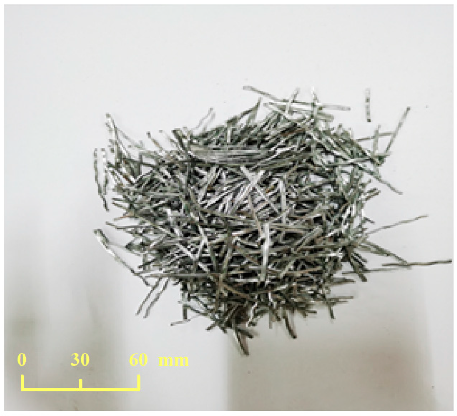
Figure 1. Steel fiber.
Applsci 14 03861 g001
Figure 2. Polypropylene fiber.
Applsci 14 03861 g002
Figure 3. Prepared concrete specimens.
Applsci 14 03861 g003
Figure 4. Electric resistance furnace chamber.
Applsci 14 03861 g004
Figure 5. Time-history curve of heating at the same heating temperature.
Applsci 14 03861 g005
Figure 6. Schematic diagram of the SHPB test system.
Applsci 14 03861 g006
Figure 7. Stress uniformity verification.
Applsci 14 03861 g007
Figure 8. Peak stress of specimens of different temperature groups at different impact air pressures.
Applsci 14 03861 g008
Figure 9. Dynamic impact peak strain of C40 plain concrete and S1PP0.2 hybrid fiber reinforced concrete under impact pressure and temperature.
Applsci 14 03861 g009
Figure 10. Dynamic impact stress-strain curves for the C40 concrete in different temperature groups.
Applsci 14 03861 g010
Figure 11. Dynamic impact stress-strain curves for S1PP0.2 HyFRC in different temperature groups.
Applsci 14 03861 g011aApplsci 14 03861 g011b
Figure 12. Failure modes of C40 plain concrete at different temperatures.
Applsci 14 03861 g012
Figure 13. Failure modes of S1PP0.2 HyFRC at different temperatures.
Applsci 14 03861 g013
Figure 14. Physical diagram of the high-speed camera.
Applsci 14 03861 g014
Figure 15. Impact compression damage process of C40 plain concrete (impact loading from the right side).
Applsci 14 03861 g015
Figure 16. Impact compression damage process of S1PP0.2 HyFRC (impact loading from the right side).
Applsci 14 03861 g016
Figure 17. Uniaxial dynamic impact compression model.
Applsci 14 03861 g017
Figure 18. Relationship between hydrostatic pressure and volumetric strain.
Applsci 14 03861 g018
Figure 19. Propagation of the 360 stress μs wave.
Applsci 14 03861 g019
Figure 20. Propagation of the 740 μs stress wave.
Applsci 14 03861 g020
Figure 21. Comparison of typical waveforms obtained from tests and numerical simulations.
Applsci 14 03861 g021
Figure 22. Comparison of stress-strain curves obtained from tests and numerical simulations.
Applsci 14 03861 g022
Figure 23. Impact compression damage process of C40 plain concrete at different impact velocities (impact loading from the right side).
Applsci 14 03861 g023
Figure 24. Impact compression damage process of S1PP0.2 HyFRC at different impact velocities (impact loading from the right side).
Applsci 14 03861 g024aApplsci 14 03861 g024b
Table 1. Technical parameters of steel fiber.
Filament Diameter (mm)Cut Length (mm)Density (kg/m3)Elastic Modulus (GPa)Tensile Strength (MPa)Ultimate Elongation (%)
135785020210002.6
Table 2. Technical parameters of polypropylene fibers.
Filament Diameter (μm)Length
(mm)
Relative Density (-)Elastic Modulus (GPa)Tensile Strength (MPa)Elongation at Break (%)
48120.914.850015
Table 3. Concrete mixing ratios.
Cement
(kg/m3)
Water
(kg/m3)
Sand
(kg/m3)
Gravel
(kg/m3)
Fly Ash
(kg/m3)
Water-Reducing Admixture (kg/m3)
4631855411261932.25
Table 4. Static compressive test results of PC and S1PP0.2 at different temperatures.
Specimen TypesStatic Compressive Strength/MPa
25°100°200°400°600°800°
PC41.642.743.736.226.514.8
S1PP0.253.256.061.251.940.027.0
Table 5. Dynamic compression test results of specimens.
Temperature/°CSpecimen CodeImpact Air Pressure/MPaPeak Stress/MPaPeak Strain
25PC-25-10.348.70.0034
PC-25-20.449.90.0039
PC-25-30.552.40.0044
S1PP0.2-25-10.371.10.0062
S1PP0.2-25-20.469.70.0072
S1PP0.2-25-30.571.80.0081
100PC-100-10.350.40.0041
PC-100-20.451.70.0052
PC-100-30.552.90.0058
S1PP0.2-100-10.371.10.0087
S1PP0.2-100-20.472.80.0112
S1PP0.2-100-30.575.60.0122
200PC-200-10.351.60.0065
PC-200-20.453.30.0074
PC-200-30.554.20.0083
S1PP0.2-200-10.379.60.0089
S1PP0.2-200-20.478.30.0119
S1PP0.2-200-30.581.40.0128
400PC-400-10.340.90.0075
PC-400-20.443.10.0099
PC-400-30.544.90.0113
S1PP0.2-400-10.363.80.0098
S1PP0.2-400-20.467.00.0128
S1PP0.2-400-30.569.00.0132
600PC-600-10.330.20.0094
PC-600-20.431.80.0109
PC-600-30.533.40.0133
S1PP0.2-600-10.349.20.0117
S1PP0.2-600-20.451.60.0147
S1PP0.2-600-30.554.00.0157
800PC-800-10.317.00.0125
PC-800-20.418.60.0134
PC-800-30.519.20.0152
S1PP0.2-800-10.333.50.0133
S1PP0.2-800-20.435.60.0157
S1PP0.2-800-30.536.50.0176
Note: “PC” indicates plain concrete, “S” represents steel fiber, and “PP” denotes polypropylene fiber; the number “0.2” of “S1PP0.2” indicates the percentage of volume mixing.
Table 6. Main parameters of the modified HJC constitutive model for C40 plain concrete.
Density ρ (kg/m3)2181Pressure at the crushing point P c (MPa)4.9
Shear modulus G (GPa)2.75Volumetric strain at the collapsing point μ c 0.000675
Normalized viscous strength A 0.45Pressure at the compaction point P l (MPa)810
Normalized pressure hardening coefficient B 1.28Volumetric strain at the compaction point μ l 0.1
Strain rate influence coefficient C 0.006Damage factor D 1 0.04
Normalized pressure hardening coefficient N 0.61Damage factor D 2 1.0
Static uniaxial compressive strength f c (MPa)14.8Pressure parameter K 1 (GPa)85
Static tensile strength T (MPa)2.38Pressure parameter K 2 (GPa)−171
Reference strain rate ε ˙ 0 (ms−1)0.001Pressure parameter K 3 (GPa)208
Total plastic strain before damage EFmin0.01Failure mode FS0.004
Normalized maximum strength SFmax7
Table 7. Main parameters of the modified HJC constitutive model for S1PP0.2 HyFRC.
Density ρ (kg/m3)2317Pressure at the crushing point P c (MPa)9.0
Shear modulus G (GPa)4.28Volumetric strain at the collapsing point μ c 0.000675
Normalized viscous strength A 0.51Pressure at the compaction point P c (MPa)810
Normalized pressure hardening coefficient B 1.42Volumetric strain at the compaction point μ l 0.1
Strain rate influence coefficient C 0.007Damage factor D 1 0.04
Normalized pressure hardening coefficient N 0.63Damage factor D 2 1.0
Static uniaxial compressive strength f c (MPa)27.0Pressure parameter K 1 (GPa)85
Static tensile strength T (MPa)3.22Pressure parameter K 2 (GPa)−171
Reference strain rate ε ˙ 0 (ms−1)0.001Pressure parameter K 3 (GPa)208
Total plastic strain before damage EFmin0.001Failure mode FS0.004
Normalized maximum strength SFmax7
Table 8. Comparison of numerical simulation results and test results.
Type of ConcreteImpact VelocityTest MethodPeak Stress Error σ Peak StrainPeak Stress Error σ Peak Strain Error ε
C40 concrete9.6 m/sTest17.00.01252.94%3.20%
Numerical simulation17.50.0121
11.8 m/sTest18.60.01344.84%2.99%
Numerical simulation19.50.0138
14.1 m/sTest19.20.01525.21%2.63%
Numerical simulation20.20.0148
S1PP0.2
HyFRC
9.6 m/sTest33.50.01334.78%0.75%
Numerical simulation35.10.0134
11.8 m/sTest35.60.01574.49%3.82%
Numerical simulation37.20.0163
14.1 m/sTest36.50.01764.11%3.41%
Numerical simulation38.00.0182
Disclaimer/Publisher’s Note: The statements, opinions and data contained in all publications are solely those of the individual author(s) and contributor(s) and not of MDPI and/or the editor(s). MDPI and/or the editor(s) disclaim responsibility for any injury to people or property resulting from any ideas, methods, instructions or products referred to in the content.