Article

Dynamically Triggered Damage Around Rock Tunnels: An Experimental and Theoretical Investigation

1
Yunnan Phosphating Group Co., Ltd., Kunming 650600, China
2
School of Resources and Safety Engineering, Central South University, Changsha 410023, China
*
Author to whom correspondence should be addressed.
Appl. Sci. 2025, 15(14), 7716; https://doi.org/10.3390/app15147716
Submission received: 1 May 2025 / Revised: 7 June 2025 / Accepted: 8 June 2025 / Published: 9 July 2025
(This article belongs to the Special Issue Advances in Failure Mechanism and Numerical Methods for Geomaterials)

Abstract

Dynamic impact experiments based on high-speed photography and digital image correlation (DIC) techniques were carried out on sandstone specimens containing arched holes to investigate the effect of the incident angle. In addition, the complex function method based on conformal mapping was used to theoretically calculate the transient dynamic stress distributions around the arched holes. The test results indicated that the strength and modulus of elasticity of the specimens under dynamic impact decreased and then increased with the increase of the inclination angle of the holes from 0 to 90° at intervals of 15°, reaching a minimum value at 60°, due to the large stress concentration at this angle leading to the shear failure of the specimen. During the experiment, rock debris ejections, spalling, and heaving were observed around the holes, and the rock debris ejections served as an indicator to identify the early fracture. The damage mechanism around the holes was revealed theoretically, i.e., the considerable compressive stress concentration in the perpendicular incidence direction around the arched hole and the tensile stress concentration on the incidence side led to the initiation of the damage around the cavity, and the theoretical results were in satisfactory agreement with the experimental results. In addition, the effect of the initial stress on the dynamic response of the arched tunnel was discussed.

1. Introduction

Arched tunnels are commonly encountered section layout formations in various engineering projects, such as underground tunnels, mining operations, and hydraulic engineering [1]. When artificial and natural dynamic disturbances are encountered in these facilities, stress wave scattering occurs in the surrounding area and causes the migration and aggregation of stress and energy [2,3], which, in severe cases, induces failures that threaten the safety of personnel and the stability of the tunnel, resulting in economic and property losses [4,5]. Therefore, understanding the failure characteristics and dynamic stress distribution around these tunnels is crucial for ensuring their stability and the safety of surrounding structures.
The failure of arched tunnels under dynamic impacts has been a subject of great interest and importance in the field of geotechnical engineering. Dynamic impacts can result from various sources, including earthquakes, blasting operations, and sudden loads during construction activities [6,7]. The behavior of arched tunnels under such dynamic loading conditions is significantly different from their response under static loading. It is generally known that dynamic loading is typically time-dependent, whereas static loading is considered time-independent [3]. In addition, the strain rate dependence of rock materials and the multiple sources of dynamic disturbances make it more challenging to estimate the dynamic failure around tunnels [8]. Nevertheless, numerous studies have been conducted to investigate the dynamic failure characteristics of arched tunnels and provided valuable insights into the failure mechanisms, energy dissipation, and stress redistribution around tunnels. The complex function method has been extensively applied to address the scattering and dynamic response problems around a hole or tunnel. Theoretical calculations of the dynamic stress distribution around the hole concentrate on the steady-state conditions. A limited number of scholars have reported on the transient dynamical response of tunnels, with a majority of studies focusing on a circular hole, and the results pointed out that the maximum stress concentration achieved around a circular hole under the action of transient P-waves is approximately 2.85–3, depending on the Poisson’s ratio, which is about 10% higher than that in a steady-state condition [9,10]. Theoretical studies revealed the scattering of stress waves and the stress distribution around the tunnels, whereas experiments are able to visualize the damage evolution under dynamic impacts, especially with the improvement of experimental techniques, high-speed photography and DIC technology, which help to capture and visualize the strain and damage evolution during the loading process [11,12,13]. Weng et al. [14] conducted an evaluation of the dynamic rupture of circular and square holes. They utilized the SHPB test system and further examined the impact of prestressing on the damage to the specimens, with the results showing that as the prestress increased from 0 to 20 MPa, the failure mode around the hole transitioned from tensile to shear, with significant shear failure occurring at 20 MPa. Qiu et al. [15] conducted both experimental and numerical simulations to explore the dynamic damage characteristics of granite specimens containing arched holes and unexposed joints subjected to dynamic impact. The findings revealed that the inclination angle of the joints markedly influenced the rockburst of arched rock tunnels and the joint angles of 56° and 134° have a more severe impact on the failure of the specimens. Previous studies have shown that under dynamic impact, pronounced tensile strain concentrations and even macroscopic tensile cracks occur on the incident side of the hole, while compressive shear failure occurs in the perpendicular incidence direction [14,15,16,17]. In addition, numerical methods provide a clear visual representation of the changes in physical quantities such as the stress, strain, and energy during the loading process. Various numerical methods, including finite element, discrete element, finite difference, and coupled numerical methods, are utilized to study the dynamic damage and stress distribution around the hole [3,18,19,20]. Coupled initial stress and dynamic loading on the damage of an arched tunnel surrounding rock was also carried out by Li and Weng [21], and the results showed when the lateral stress coefficients are 0.25 and 3, while the dynamic incident stress increases from 30 to 50 MPa, resulting in more severe damage to the surrounding rock, transitioning from spalling to rockburst. These numerical methods offer valuable insights into the behavior and effects of the cavity under different dynamic loading conditions. Despite the significant amount of research conducted on the dynamic response of tunnels through experimental, numerical simulation, and theoretical studies, most of the previous studies have focused on the dynamic response of the steady state. Investigations on the damage process, mechanism, and stress distribution of arch tunnels under dynamic impacts from different directions still need to be carried out in order to contribute to a comprehensive understanding of dynamically triggered failure in underground space engineering.
In this study, a set of specimens containing arched holes with different inclinations was employed to carry out dynamic impact experiments combined with high-speed photography and DIC techniques to simulate the failure characteristics of tunnels. The strain evolution and damage patterns of the specimens were captured; furthermore, the transient dynamic stress distributions around the arched holes were theoretically calculated based on the complex function method and conformal mapping to reveal the effect of the incidence angle on the failure mechanism. The findings of this research will have significant implications for the design and construction of underground structures, ensuring their stability and the safety of surrounding areas, and they also provide a theoretical supplement for the transient-to-steady-state transition of stress wave scattering within the framework of complex variable functions.

2. Experimental Setup

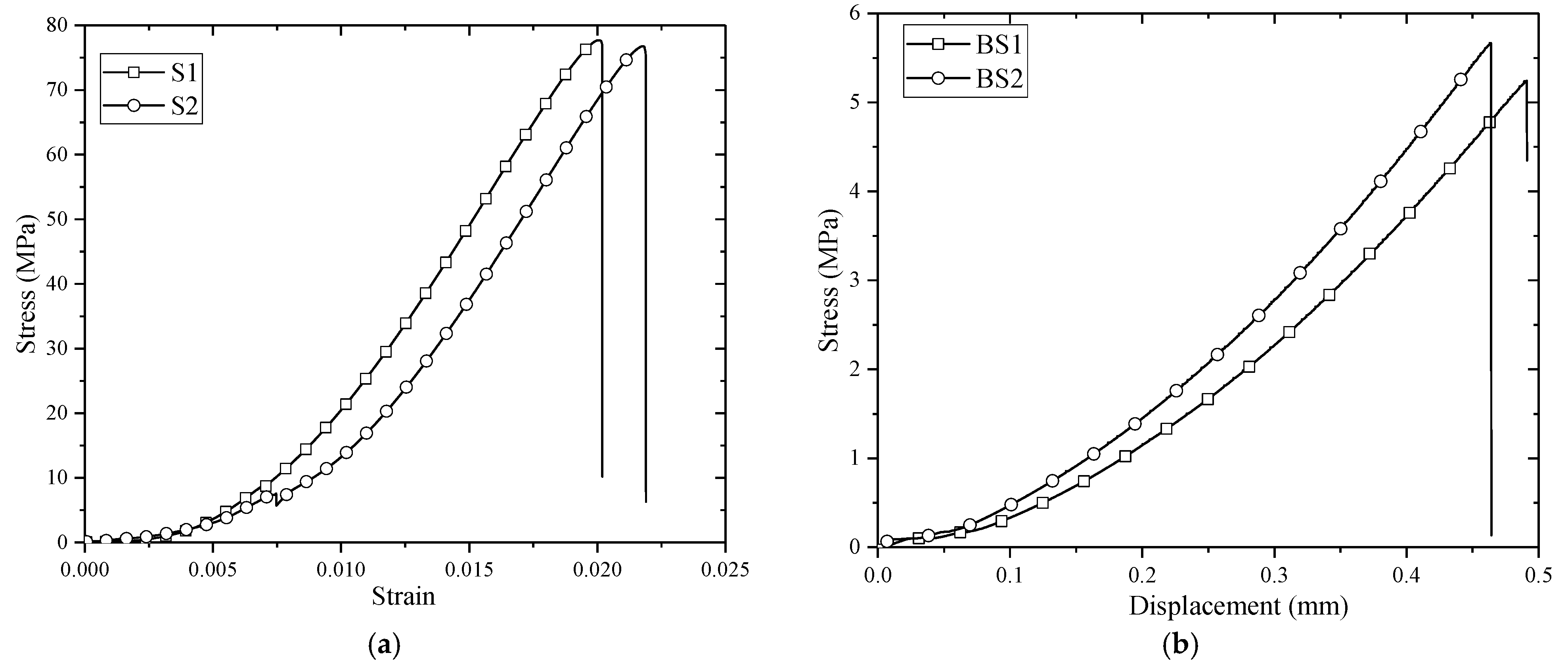
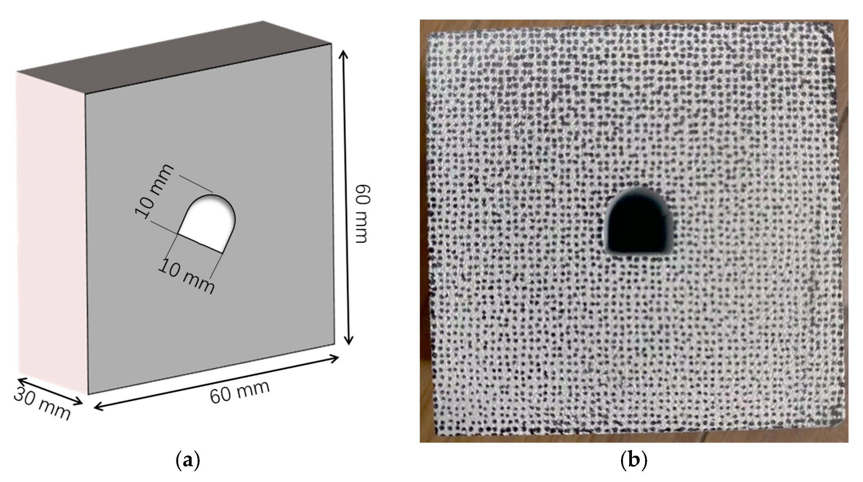
2.1. Sample Preparation and Material Characteristics

The specimens were cut from the same large block of gray sandstone, resulting in samples with dimensions of 60 × 60 × 30 (mm). Uniaxial compression experiments and indirect tensile experiments were carried out to obtain the basic mechanical parameters of the sandstone, and according to the IRMS suggested methodology [22], the results of standard specimens under uniaxial compression and Brazilian disc experiments were obtained, as shown in Figure 1.
Through experimentation, some fundamental mechanical parameters of the sandstone matrix are shown in Table 1.
For the dynamic impact experiments, arched holes with different inclinations were drilled into the sandstone specimens using waterjet cutting, as shown in Figure 2. The inclinations angle (β) was set at 0°, 30°, 45°, 60°, and 90°, respectively. After the completion of the experiment, a matte white coating was sprayed onto the specimens, and random speckles were applied to prepare for the subsequent surface deformation measurements. Speckles were sprayed on the specimen surface in the region of interest (ROI). The position aperture and focal length of the high-speed camera needed to be adjusted to ensure that each scatter point on the sample’s surface was visible and did not produce any luminous surface.

2.2. Test System

The SHPB test system cleverly avoids the difficulty of directly measuring the strain stress of an object under high-speed loading [23]. It is being increasingly used to test the dynamic mechanical properties of materials [24,25]. The modified SHPB system, as illustrated in Figure 3, was used for the dynamic impact, primarily comprised of the driving device, an incident bar, a transmission bar, an energy trap at the rear end, and the data acquisition system. High-speed photography and digital image correlation (DIC) technology were also employed to observe the deformation evolution of the specimens during the dynamic impact process. DIC is a non-contact surface deformation measurement technique widely used in dynamic and static mechanical performance testing of materials [12,13,26]. In this study, the high-speed photography resolution was set as 256 × 256 pixels at a frame rate of 79,161 fps. Two coaxial lights were used as the light source to ensure that no shadows or reflective areas were produced on the specimen. After the experiment, the pictures were processed using VIC-2D v7 software with the default parameters, which achieved good results.
In each experimental process, the striker was carefully repositioned to a fixed location, ensuring consistent application of pressure as the driving force. This meticulous action aimed to minimize the external disturbances and maintain uniform incident stress for every specimen. The focus of this experiment was on analyzing the fracture process surrounding the arched hole under constant incident stress, with a peak value of approximately σd = 100 MPa.
As the striker hits the end of the incident bar, the stress wave will propagate ahead as strain in the bar and be recorded by the strain gauges on the bars. The stress at both ends of the sample near the incident and transmission bars σin and σtr can be written as follows [23]:
σ i n = E ε i + ε r + σ t r = E ε t
where E is the elastic modulus; and εi, εt, εr are the incident, transmission, and reflected strains, respectively. It is worth noting that the incident and transmission strains represent compressive strain, marked as negative (−), and the reflected strain denotes the tensile strain, marked as positive (+). Afterward, the stresses and strains in the specimen can be determined by the three-wave method [13,27]. Table 2 lists the main equipment used in this test.

3. Experimental Results and Analysis

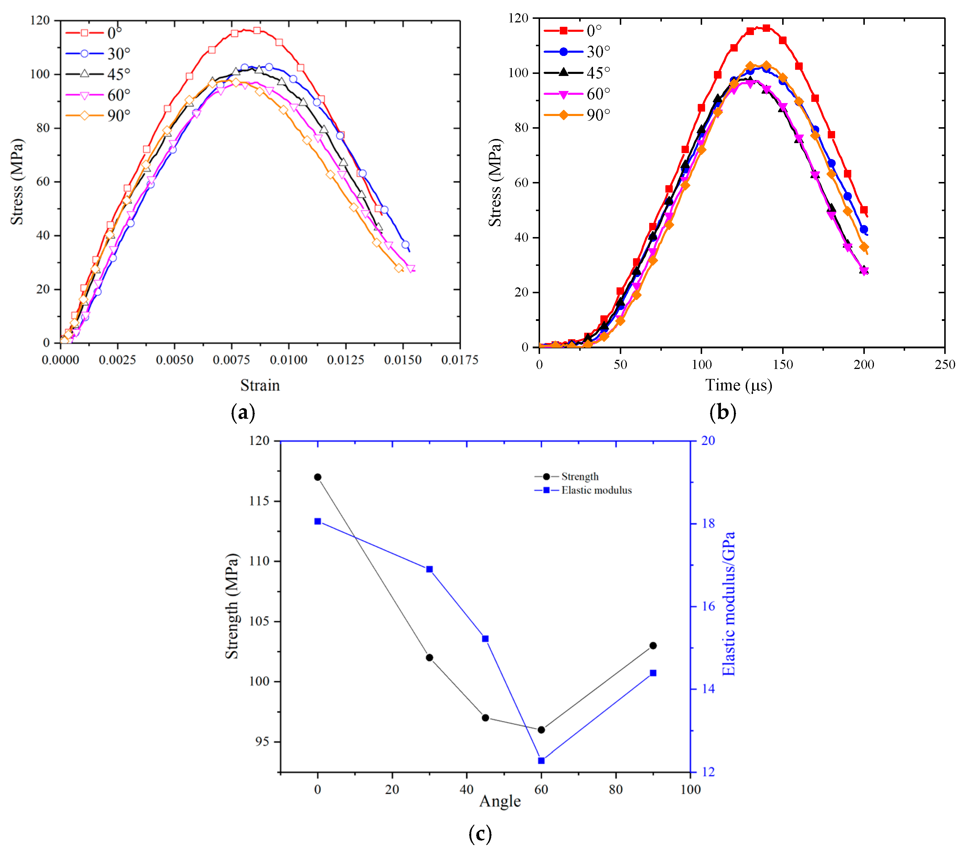
3.1. Dynamic Mechanical Properties

The stress–strain relationship and elastic modulus of the specimens exhibit comprehensive responses to its dynamic mechanical properties. Three tests were carried out for each specimen. Since the improved SHPB equipment does not require a waveform shaper, the waveforms generated by each impact are almost identical, ensuring the stability of both the waveforms and the results. As a result, the curves obtained from nearly every test are very similar, with a standard deviation of approximately 1.5 MPa. Figure 4a presents the typical stress–strain curve during the loading process, Figure 4b illustrates the loading time course, and Figure 4c depicts the relationship between the peak load, dynamic elastic modulus, and hole inclination angle. From Figure 4, it can be observed that the dynamic modulus of elasticity and compressive strength of the specimen remain higher than the values observed under static conditions, even when it contains a hole. Furthermore, the hole inclination angle significantly influences the mechanical properties of the specimen. As the inclination angle increases, the changes in the strength and elastic modulus exhibit a consistent trend. For inclination angles less than 60°, the strength and elastic modulus display a negative correlation with the angle, whereas for angles greater than 60°, they increase with the angle. The highest strength and elastic modulus are reached at an inclination angle of 0°. The decrease in the strength and elastic modulus around 60° can be attributed to the shear-favorable angle, as specimens with holes at this inclination angle exhibit a similar reduction in strength [28].

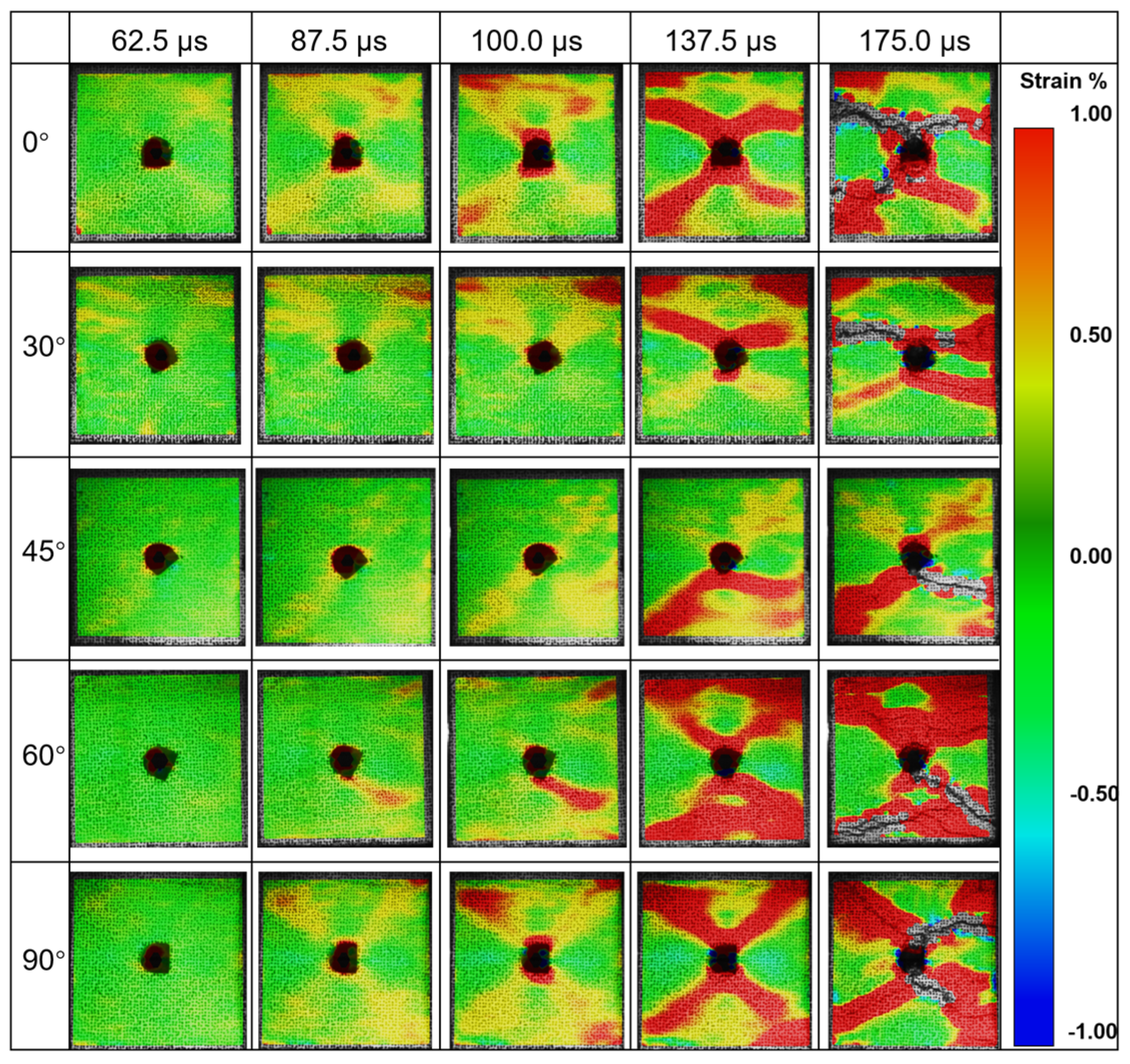
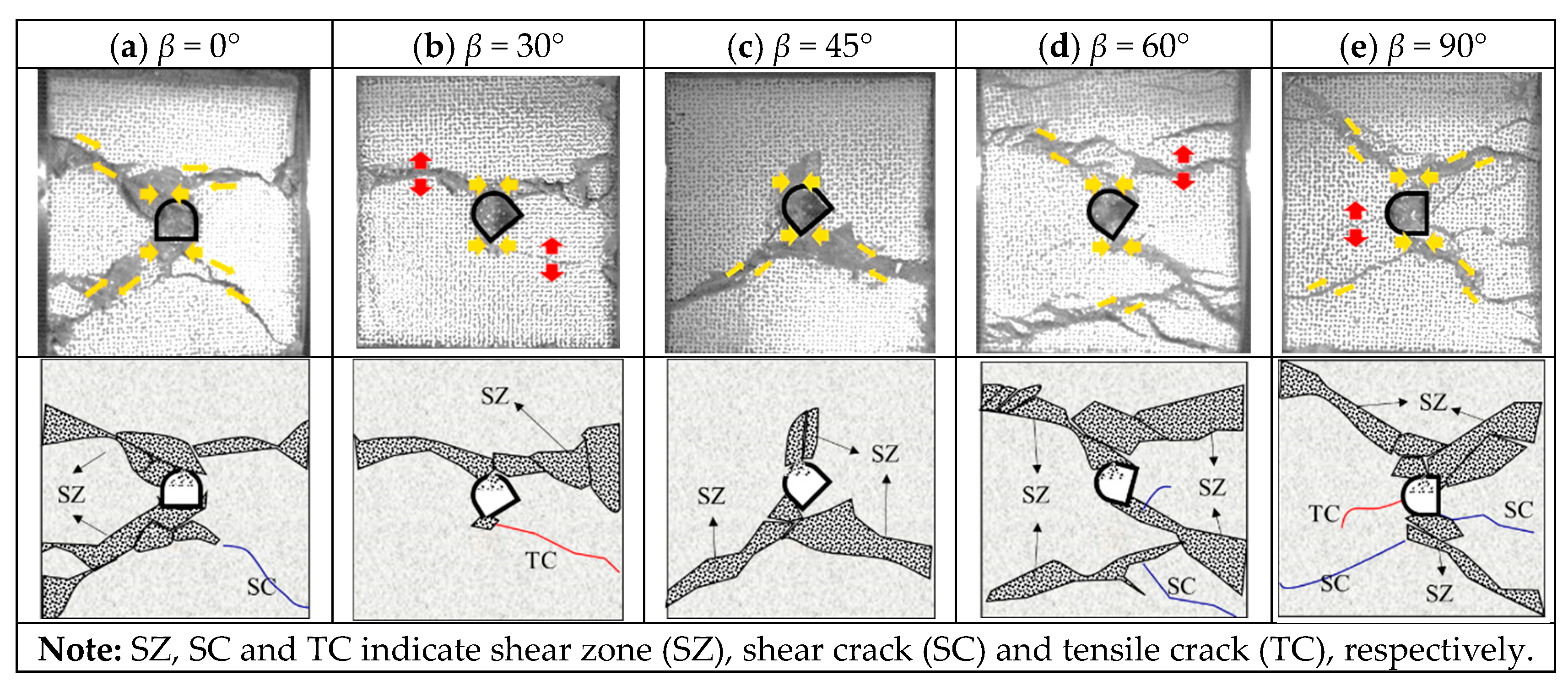
3.2. Fracture Process of the Sample

The photographs of the specimens captured by a high-speed camera were processed by the DIC technique to obtain the evolution of the surface deformation of the specimens during the dynamic loading process [13,29]. The damage to the specimen at different times under dynamic loading and the final damage pattern are given in Figure 5. The figures clearly show that the deformation of the specimen starts at the edge of the hole, forming a strain concentration, due to the concentration of dynamic stresses. When the incident wave reaches the edge of the hole, scattering and refraction occurs at the edge of the hole, resulting in an increase and decrease in the local stress. Damage occurs first in the region of increased stress because the stress distribution at the edge of the hole is affected by the inclination angle, so the deformation distribution of the specimen is not the same under the same incident stress. Combining the deformation of the specimen, the stress–strain curve and the loading time curve, it is possible to obtain the deformation characteristics of the specimen under different dynamic stress states.
It is visible in Figure 5 that a pronounced strain concentration occurs at the hole’s edge at t = 62.5 μs, and the corresponding stresses are determined in combination with the loading time curve to be 31.5 MPa, 27.5 MPa, 27.1 MPa, 27.3 MPa, and 23.4 MPa for the inclination angles of 0°, 30°, 45°, 60°, and 90°, respectively. These values are much smaller than the static compressive strength of the specimen, but as a result of the dynamic stress concentration, the incident stresses are amplified and reach the strength limit of the rock, so that the initial fracture of the specimen is formed at the edge of the hole. The inclination of the hole in the specimen corresponds to different incident angles, which directly affects the stress distribution around the holes.
The early failure of the hole edge is dominated by the stress concentration, and as loading continues, the specimen cracks penetrate to form an X-shaped fracture zone, which follows the same damage pattern as specimens containing a circular hole and crack defects [6,16]. At the inclination of 0°, the initial strain concentrations are formed at the top and bottom of the arch, and at inclinations of 30° to 60°, the strain development followed a similar pattern at the side walls of the holes, with the tensile strain concentrations in the incidence direction, followed by the strain concentrations at the left foot of the arch and at the top of the arch. In the case of 90°, the two side walls of the hole first experienced strain concentrations and then the crack initiated to penetrate the whole sample at this location.
As can be observed in Figure 5, the strain concentrations are initially generated in the incident direction at the edge of the hole and in the proximal perpendicular incident direction before overall damage to the specimen occurs. The strain concentration in the incident direction can be identified as tensile strain. However, it is only at an inclination angle of 90° that the tensile strain develops into macroscopic tensile cracks. The final fracture pattern of the specimens is plotted in Figure 6.
It is noticed that almost all the specimens are damaged due to crack initiation in the region of the strain concentration, and then the cracks develop and connect, eventually penetrating the whole specimen. In addition, the damage to the specimen is dominated by compressive shear, initially forming a localized shear region around the hole accompanied by debris ejection.

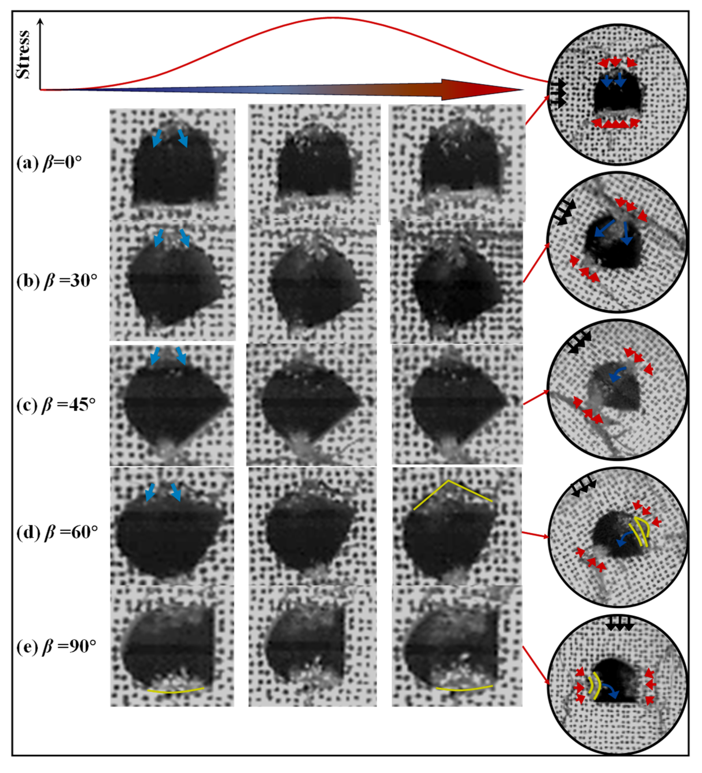
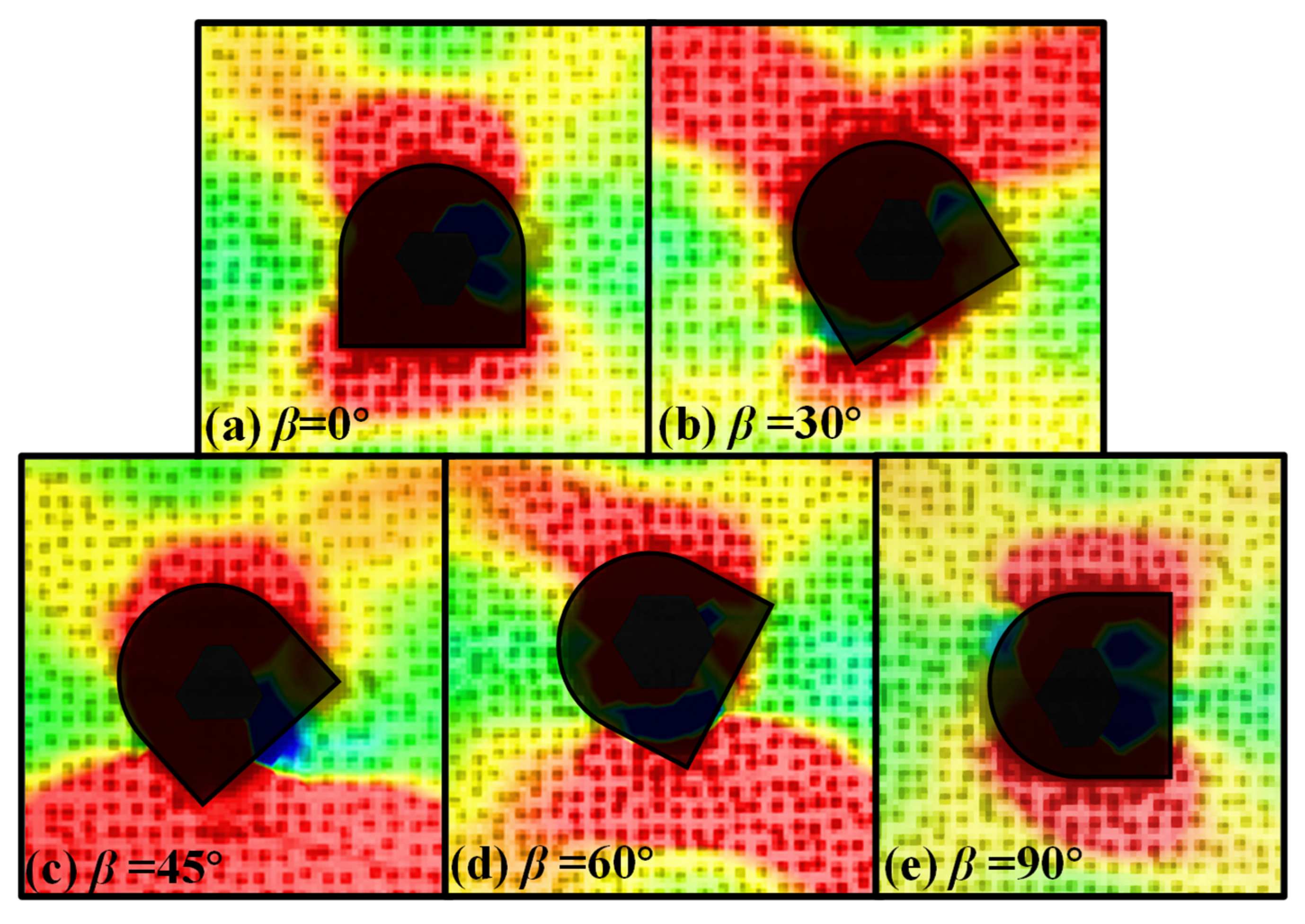
3.3. Damage Around the Arched Hole Under Impact

In the previous analysis, the sandstone specimen with an arched hole was considered a unified entity, focusing on the overall damage caused by dynamic impact. The mechanical properties of the flawed rock formation can be assessed using one-dimensional stress wave theory, such as the three-wave method, to obtain its stress–strain curve. This approach has been adopted by many researchers to determine the influence of cracks, holes, and other defects on the overall load-bearing capacity and damage mode of the specimen. While this is valuable for evaluating the strength of the rock formation, it may not provide a clear assessment of the dynamic stability of underground spaces. Therefore, in addition to analyzing the overall dynamic response of the specimen, our focus extends to examining the deformation and destabilization characteristics of the arched hole under dynamic impact. This is approached as a two-dimensional problem, considering the stress wave scattering and dynamic stress concentration in the surrounding rock of the tunnel. The surrounding rock damage characteristics of the arched hole, determined through indoor experiments, provide further insights into the deformation and damage patterns of rock tunnels with arch-shaped sections exposed to dynamic perturbations. This understanding is crucial for revealing the dynamic damage mechanism of rock tunnels in underground spaces. Figure 7 illustrates the captured damage process at the edge of the hole.
In Figure 7, the observed rock damage at the edge of the hole is categorized into the following types:
(I)
Heaving, which is manifested when the top and bottom of the specimen experience significant compressive stress at a 0° incident angle. Under this condition, the bottom is compressed and protrudes toward the center free surface, resulting in the formation of a heave.
(II)
Rock ejection, which is observed in almost all cases, primarily at the top of the arch, the arch shoulder, and the foot of the arch. This rock ejection is a result of the progressive accumulation and subsequent release of strain energy around the circumference of the arched hole during dynamic impacts. A portion of this energy is converted into kinetic energy, resulting in the ejection of rock debris [30].
(III)
Spalling, which occurs in the side walls, is induced by the same mechanism as (I). This is a consequence of an elevation in the circumferential compressive stress [31] during dynamic disturbances. A stress gradient is formed within a localized area, causing deviations in the direction of principal stresses. This ultimately leads to the spalling of surrounding rock from areas experiencing higher stress levels.
The five different cases are classified into three major categories based on the incident direction of the dynamic disturbances: horizontal incident, inclined incident, and vertical incident. In these three scenarios, severe compressive–shear failure always occurs perpendicular to the incident direction in the arched hole. Radial tensile strain is evident in the early stages of loading on the incident side, and macroscopic tensile cracks only form in the 90° incident case. Due to the small ratio between the specimen size and the incident wavelength used in the experiments, radial tensile stress concentrations are not generated in such cases, and radial tensile stresses tend to occur at wavelengths 3–5 times the radius of the hole [3,32]. In the vast majority of cases, the ejection of rock debris occurs during the initial stages of loading. As the loading progresses, these areas of rock debris ejection further evolve and contribute to the formation of the macroscopic damage pattern described earlier. Therefore, the ejection of rock debris serves as an early indication of dynamic destruction in the surrounding rock.

4. Stress State Around the Arched Hole Under Dynamic Impact

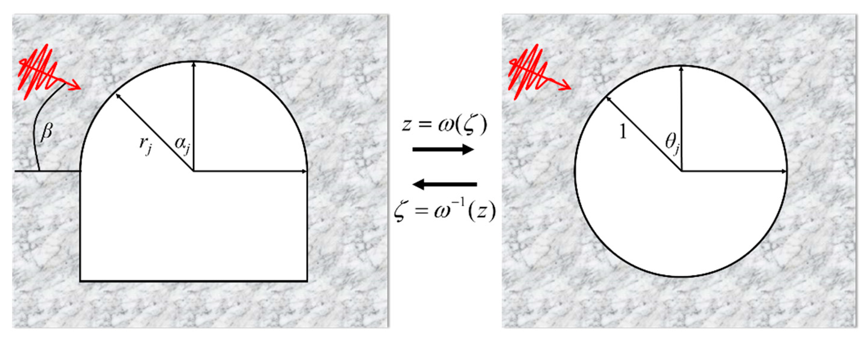
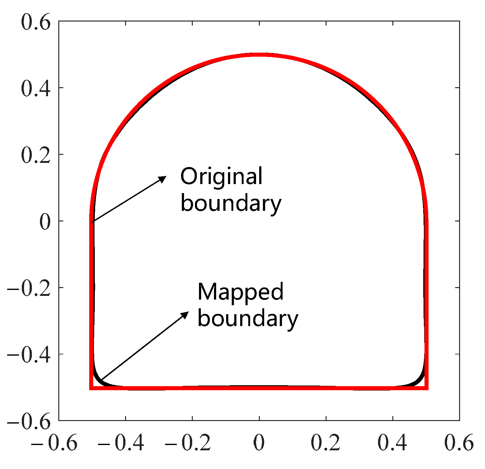
4.1. Conformal Mapping of Arched Hole

As mentioned, the damage at the periphery of an arched hole should be considered a two-dimensional stress wave scattering problem. The parallel orientation of the upper and lower surfaces of the specimen with respect to the direction of impact eliminates wave reflection upon incidence. Reflection and transmission occurring at the interfaces at both ends have no effect within the observation period. Consequently, the problem can be simplified to the scattering of stress waves in the vicinity of an arched cavity within a fully planar space. In order to understand the mechanism behind this damage, it is crucial to determine the stress distribution around the hole, as stress is the primary factor influencing material failure. Typically, for a circular hole subjected to static pressure, the stress distribution at the hole can be obtained using Kirsch’s solution [33]. However, when the hole is subjected to dynamic loading, the stress distribution is obtained through the wave function expansion method. Analytically obtaining the stress distribution around a complex boundary is extremely challenging. Therefore, it is necessary to transform the complex boundary into a unit circle using complex functions and the conformal transformation method as shown in Figure 8. This transformation can be expressed in the form of a Laurent series [34]:
z = w ( ζ ) = R ζ + k = 0 C k ζ k ,       | ζ | 1
Here, w(ζ) is a holomorphic function, z and ζ are complex variables, Ck is the Laurent expansion coefficient, and R is the shape-dependent scale factor. Expanding Equation (2) in the complex plane gives:
r j e i α j = R e i θ j + k = 0 C k e i k θ j
Here, θj and αj are the corresponding polar angles in the physical and image planes, and rj is the polar diameter in the physical plane.
Applying Euler’s formula to Equation (3) and separating the real and imaginary parts, the following two equations can be obtained:
sin α j θ j + k = 0 C k sin α j + k θ j = 0 r j = R cos α j θ j + k = 0 C k cos α j + k θ j
R = r 1 / 1 + k = 0 n 1 C k
The problem described in Equations (4) and (5) can be approached as a constrained optimization problem [35] to find an approximate expression for the finite term, aiming to minimize the error between the mapped shape and the original shape. Alternatively, the problem can be directly solved by truncating the series using an analytical method [36]. It is widely accepted that a satisfactory mapping shape can be achieved by expanding the Laurent series to include 6–7 terms. Specifically, for the arched shape shown in Figure 1, its corresponding mapping function can be derived as follows:
w ( ζ ) = 0.5424 ζ 0.059 0.0036 ζ 1 + 0.0458 ζ 2 0.0432 ζ 3 + 0.018 ζ 4 + 0.004 ζ 5 0.0046 ζ 6
Figure 9 plots the mapped shape determined by Equation (6) and the original shape. It can be seen in the figure that the mapped shape is almost identical to the original shape, except at the arch foot, where the original shape is a right angle and the mapped shape is a rounded corner with a small chamfer, but it is in a match with the specimen drill holes in Figure 1, where the holes in the specimen are similarly rounded with a tiny rounded corner.

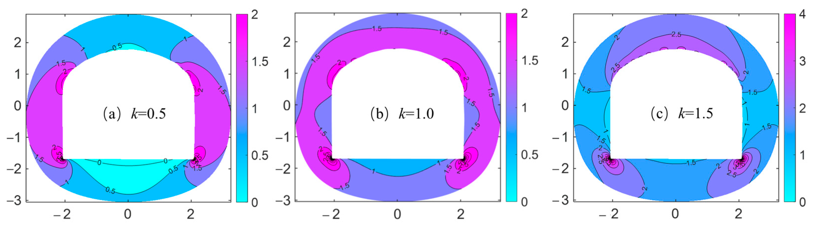
4.2. Dynamic Stress Distribution Around an Arched Hole

The dynamic impact is a transient process and it is necessary to first obtain the steady-state dynamic stress distribution around the hole and then use Fourier transform technology to bridge the gap between the steady state and the transient state. The complex function method has long been employed to solve the scattering of stress waves and the stress distribution around complex boundary shapes in steady-state dynamics problems. Building upon Liu et al.’s [37] research, this section focuses on resolving the transient dynamic stress distribution around an arched hole.
A simple harmonic plane P-wave incident at circular frequency ω and angle of incidence β, omitting the time factor eiωt, can be expressed in the complex plane as [37]:
φ i = φ 0 n = n = i n J n k p | w ( ζ ) | w ( ζ ) | w ( ζ ) | n e i n β
Here, Jn() is the first-type Bessel function of the nth order, kp is the wavenumber of the P-wave and kp = ω/cp. The incident P-wave scatters around the hole and a reflected P-wave and SV-wave are generated. According to the asymptotic properties, the reflected P- and SV-wave potential can be written as:
φ r ( ζ , ζ ¯ ) = n = A n H n 1 ( k p | w ( ζ ) | ) w ( ζ ) | w ( ζ ) | n
ψ r ( ζ , ζ ¯ ) = n = B n H n 1 ( k s | w ( ζ ) | ) w ( ζ ) | w ( ζ ) | n
Here, kp is the wave number of the S-wave and ks = ω/cs, and An, Bn are the undetermined mode coefficients, which can be determined by the stress boundary condition. Then the full-wave fields around the hole can be expressed as:
φ = φ ( i ) + φ ( r ) ψ = ψ ( r )
Based on Hooke’s law, in the polar system, each of the stress components around the hole can be expressed as:
σ ρ + σ θ = 2 α 2 ( λ + μ ) φ σ θ σ ρ + 2 i τ ρ θ = 8 μ 2 z 2 ( φ + i ψ ) e 2 i ϑ
where λ and μ are Lamé constants, and:
e i ϑ = ζ w ( ζ ) ρ ¯ w ( ζ )
The inner surface of the hole is a free boundary, and without considering the initial stress and body force, the radial and shear stresses on the inner surface of the hole are zero. Thus, the stresses’ boundary condition in the ζ-plane are expressed as:
σ ρ + i τ ρ θ ζ = e i θ = 0 σ ρ i τ ρ θ ζ = e i θ = 0
Further, by substituting Equations (7)–(12) into Equation (13) and after item shifting, the following algebraic equations can be obtained:
n = ε n 11 A n + n = ε n 12 B n = ε 1 n = ε n 21 A n + n = ε n 22 B n = ε 2
where ε n i j and An, Bn is a row vector of 2n + 1, ε n i j and ε i is the contribution of P- and S-waves to the stress component [37]. By multiplying eimθ at both ends of the above equation and integrating over (−π, π), an infinite set of algebraic equations about An and Bn is obtained as follows:
ε n m 11 ε n m 12 ε n m 21 ε n m 22 A n B n = ε 1 m ε 2 m                 m , n = 0 , ± 1 , ± 2 , ± 3
Here, ε n m i j = 1 2 π π π ε n i j e i m θ d θ , ε i m = 1 2 π π π ε i e i m θ d θ ; i, j = 1, 2; and ε m n i j is a square matrix of order 2n + 1. ε i j m is a row vector of 2n + 1. The Gauss–Legendre numerical integration method is employed, which gives a higher-accuracy result, and then An and Bn can be determined accordingly.
The dynamic stress concentration factor (DSCF) is defined as the ratio of the circumferential stress around the hole and the maximum stress generated by the incident P-wave, expressed as:
σ θ * = σ θ σ 0
where:
σ 0 = μ β 2 σ θ = 2 α 2 ( λ + μ ) φ ω ( ζ ) , t
From Equations (16) and (17), one obtains:
σ θ * ( ω , θ ) = 2 κ 2 1 κ 2 Re n = A n H n ( 1 ) ( α | w ( ζ ) | ) w ( ζ ) | w ( ζ ) | n + φ i e i ω t
where:
κ 2 = 2 ( 1 ν ) ( 1 2 ν ) 2
For this study, the transient incident wave generated by the SHPB can be simplified as a half-sine excitation function:
f ( t ) = sin ( π t t 0 ) , 0 t < t 0 0               , t t 0
Here, t0 is the duration of the incident wave. Meanwhile, according to the Fourier transform techniques and Duhamel integral method, the transient DSCF can be obtained [9,38]:
σ ¯ θ θ * = 0 σ θ * ( ω , θ ) ω cos ω t cos ( π t / t 0 ) π ω t 0 cos ω t cos ( π t / t 0 ) π + ω t 0 d ω , 0 t < t 0 0 σ θ * ( ω , θ ) ω cos ω t cos ( π + ω t ω t 0 ) π ω t 0 cos ω t cos ( π + ω t 0 ω t ) π + ω t 0 d ω   , t t 0
The stress distribution around the arched hole at different moments during impact is obtained by programming the calculations of Equations (18) and (21), as plotted in Figure 10. In a theoretical analysis, the stress distribution around a hole is solely proportional to the ratio between the wavelength and the size of the hole, irrespective of the actual dimensions of the hole. Therefore, the theoretical results are applicable to a hole or a tunnel.
When a dynamic load interacts with the arched hole surroundings, it becomes evident that the stresses undergo both amplification and attenuation. The location of these changes is closely linked to the direction of incidence. Irrespective of the angle of incidence, in the incidence direction, there is a noticeable weakening of stress or even a concentration of tensile stress, while in the perpendicular direction of incidence, compressive stress concentration occurs. In conjunction with Figure 10, the mechanism behind the damage in Figure 7 can be elaborated, that is, due to the impact, a location on the surrounding rock (e.g., the floor, the side walls, the roof arch, etc.) is not in a uniform state of stress, and as a result, a stress gradient is generated, as shown in Figure 10, and the area subjected to a greater stress in such a stress environment suffers from violent destruction. It is important to note that when the stress wave reaches the periphery of the hole, both tensile and compressive stress concentrations are generated almost simultaneously. However, as the applied stress increases, the compressive stress concentration continuously increases, while the tensile stress concentration remains relatively constant. At the incidence angle of 90°, the arch roof location experiences a higher tensile stress concentration compared to the other angles. This higher concentration of tensile stress is responsible for the occurrence of an early-stage tensile strain concentration, as shown in Figure 5, and the formation of macroscopic tensile cracks in the case of β = 90°.
In the elastic phase, the strain of the material is linearly related to the stress, and the distribution of the strain can be a good indication of the distribution of the stress. Figure 11 plots the strain distribution around the arched holes at t = 112.5 μs, and it is evident that the strain distribution around the holes coincides with the stress distribution in Figure 10.
The corroboration between the theoretical and experimental results strongly suggests that the application of the complex function method and the conformal mapping to estimate the dynamic stress distributions around the arched hole provides a good insight into the deformation and damage mechanisms under dynamic impacts.

5. Discussion

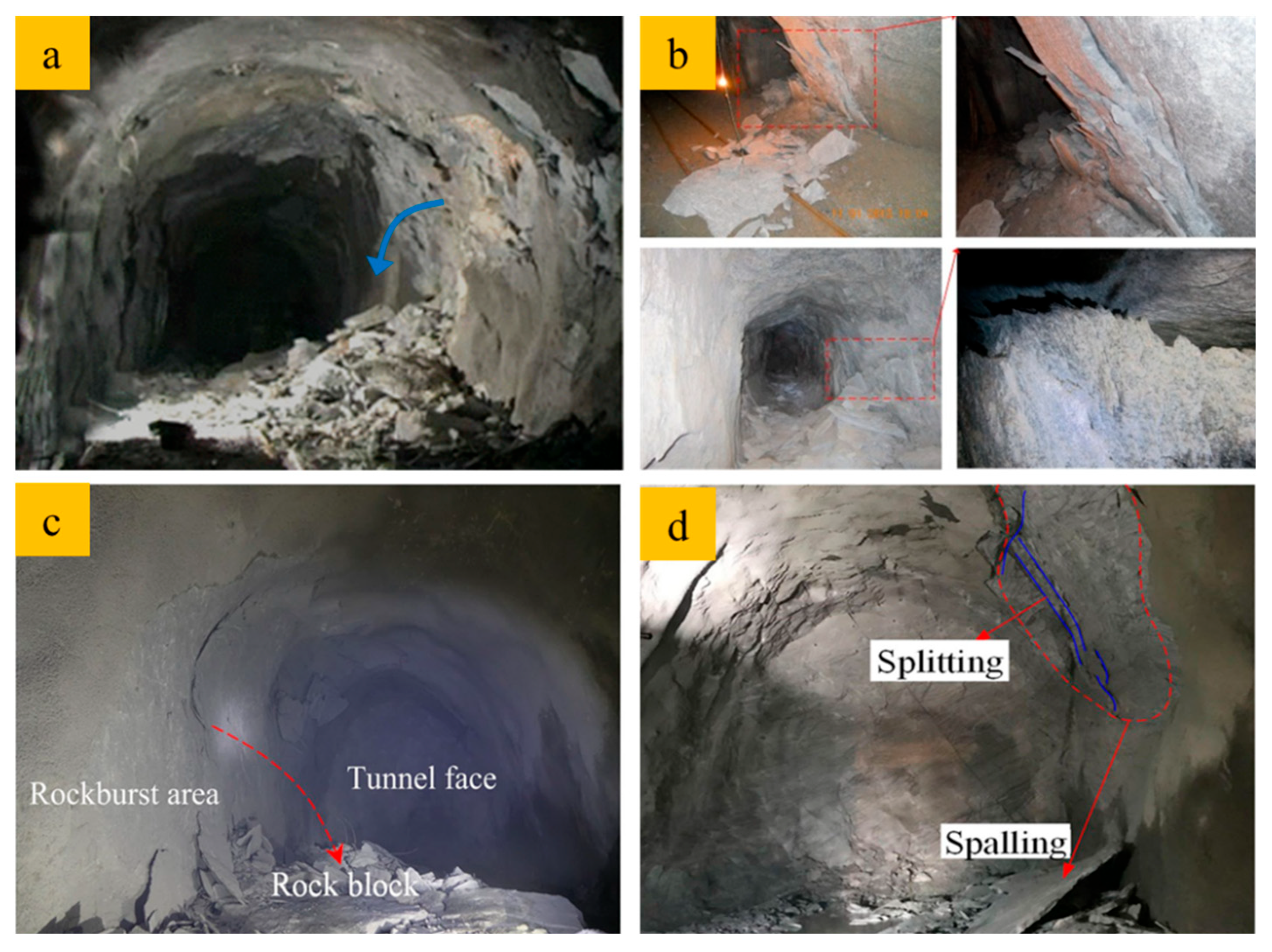
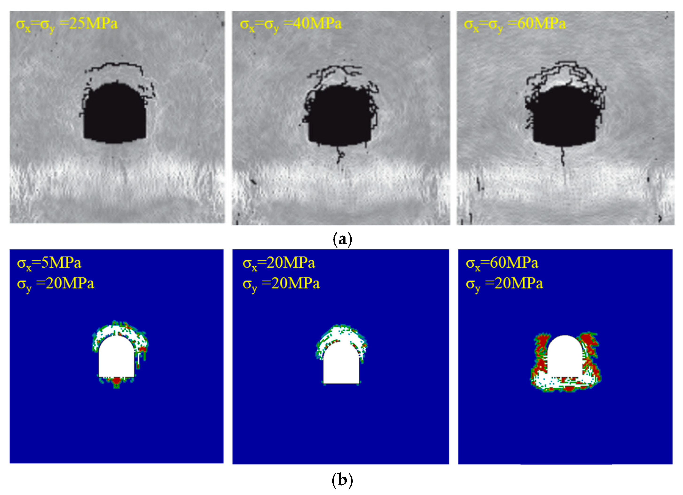
5.1. Insights from Experimental Results for In Situ Observations

Through conducting indoor impact experiments and transient dynamic analysis based on complex variable functions, the damage patterns and mechanisms of arched holes under dynamic impact have been thoroughly evaluated. The effects of different dynamic incidence angles on the stress distribution and deformation development around the arched hole were analyzed. As a common form of underground space section, the arched shape is widely used in mining and hydraulic engineering [39]. In practical engineering, dynamic disturbances come from all directions, such as blasting construction [40], far-field earthquakes [41], rockfall impacts, etc. These dynamic disturbances impose risks on existing tunnels, potentially triggering rockburst and spallation [3,21,42]. Some typical geotechnical catastrophe patterns of arched tunnels under dynamic disturbances are presented in Figure 12.
Coincidentally, the destruction patterns presented in Figure 12 are matched in Figure 7, which indicates that small-scale laboratory experiments are capable of reproducing engineering-scale destruction to a certain extent, and this also highlights the necessity and reliability of this study. Therefore, their damage mechanisms are similar, i.e., under the action of dynamic disturbances due to a local concentration of tensile/compressive stresses. In Figure 7e, spalling failure is observed, which is not caused by dynamic tensile forces but by compression [31]. Spalling resulting from dynamic tensile was not detected in this experiment [45] due to the utilization of incident wavelengths much larger than the hole size (wavelength/hole radius > 100). When the incident wavelength is small relative to the hole size (wavelength/hole radius < 20–30), the stress wave is treated as reflected tensile stress between the stress wave and the tunnel. However, with incident wavelengths significantly greater than the tunnel size, the stress wave is considered to be scattered around the tunnel [3,32]. In situations where short-wavelength incidence occurs, radial tensile stresses are generated on the incident side due to reflection, resulting in the occurrence of spalling damage [46]. Conversely, in cases of long-wavelength incidence, the stress wave diffracts around the hole, avoiding the generation of radial tensile stress and instead leading to the concentration of circumferential tensile stresses.

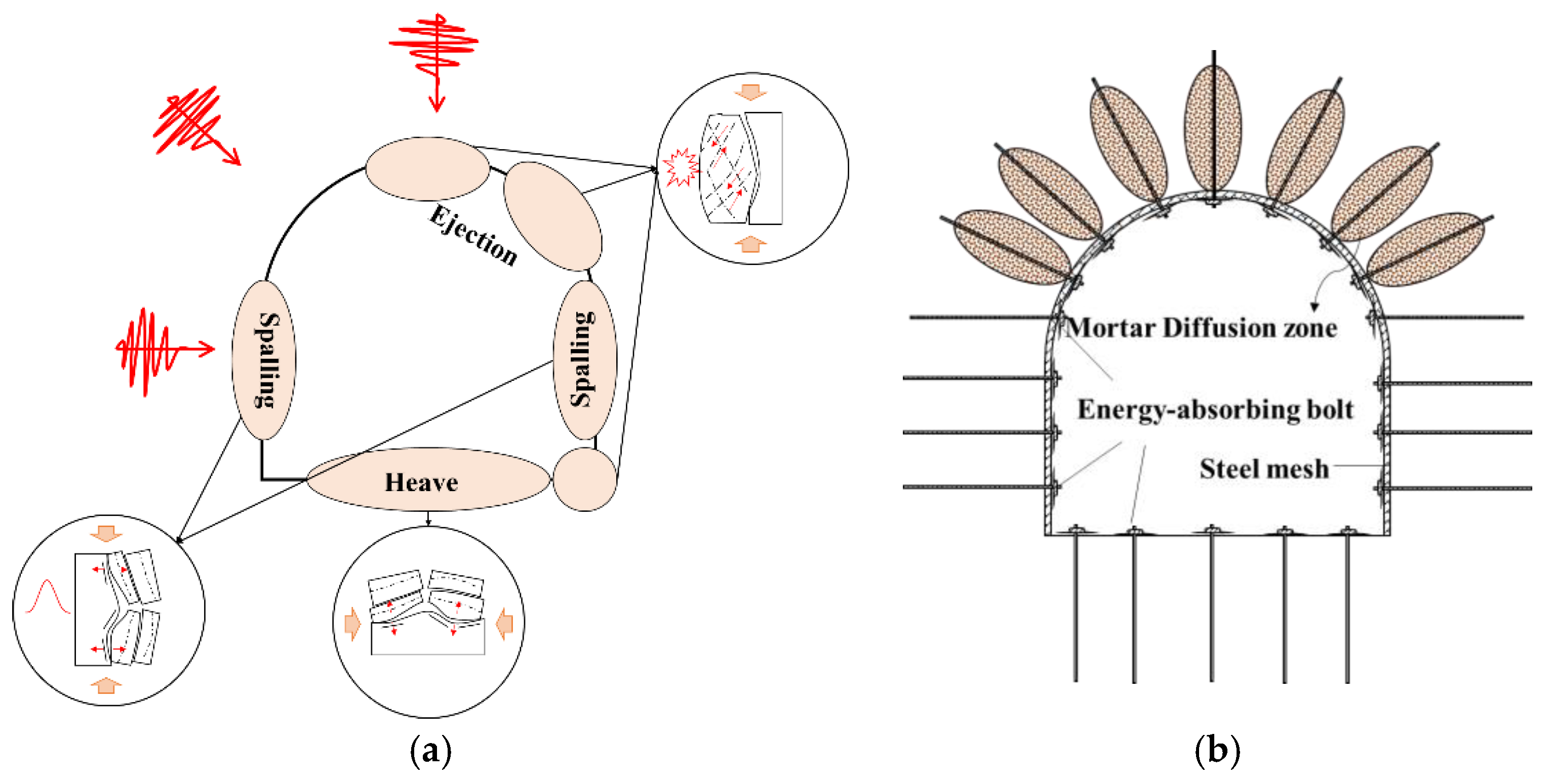
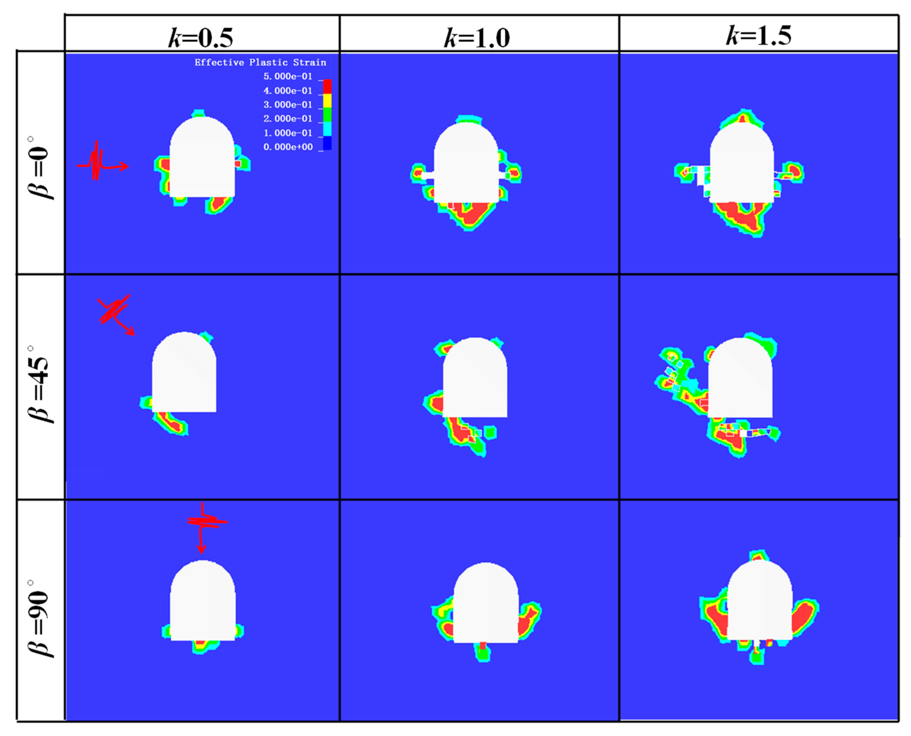
5.2. Influence of Dynamic Disturbance Direction on Damage Distribution and Potential Support Systems

Combining the dynamic stress distribution and examining the failure patterns of arched tunnels under dynamic disturbances, both in the field and in the laboratory (Figure 7 and Figure 12, respectively), potential failure illustrations and support systems can be proposed, as depicted in Figure 13.
In Figure 13a, it can be observed that when a dynamic disturbance is horizontally incident, compression damage is evident at the top and bottom of the tunnel, with spalling damage occurring at the sidewalls. Conversely, in the case of vertical incidence, slabbing or spalling failure is observed in both sidewalls. Thus, different support methods are utilized for different areas. A compression damage zone exists at the top, necessitating the use of mortar anchors to enhance the overall integrity and support capacity of the rock mass. On the other hand, the side walls and arch shoulder region experience ejection under dynamic perturbation, indicating a remarkable storage of energy in this area. Therefore, energy-absorbing bolts such as negative Poisson’s ratio bolts [47] and D-bolts [48] are employed for support. These bolts effectively dissipate the kinetic energy of the rock mass, helping to prevent and control rockbursts and other violent dynamic disasters.

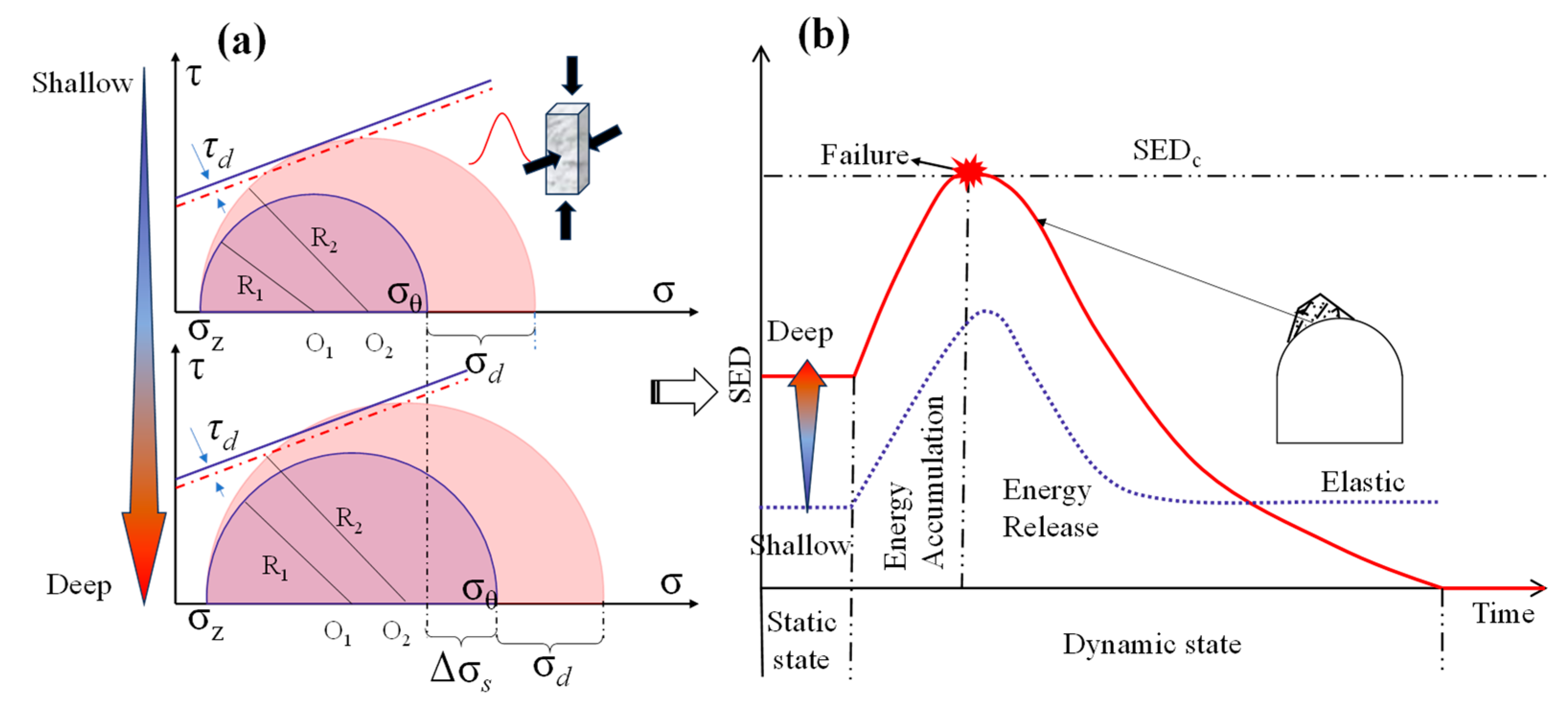
5.3. The Role of Geo-Stress and Dynamic Disturbances in Tunnel Failure

In engineering construction, there are preexisting initial stresses that must be taken into consideration. Therefore, the calculation of the stress concentration around the arch-shaped hole under different static stress conditions was conducted, revealing that a significant static stress concentration occurs around the chamber under different lateral pressure coefficients, as shown in Figure 14.
As shown in Figure 14, a static stress concentration always produces larger compressive stress concentrations in the direction perpendicular to the maximum principal stress. Under these conditions, when the chamber is subjected to external dynamic disturbances, the surrounding rock mass is in a state of superposition of dynamic and static stresses. When the dynamic load reaches the vicinity of the chamber, the circumferential stress in the surrounding rock is either enhanced or weakened. When the incident direction is parallel to the static maximum principal stress, the overlapping region of static and dynamic stress concentrations increases, leading to enhanced tensile and compressive stresses around the chamber, which results in more severe damage to the surrounding rock. Conversely, when the direction of the dynamic disturbance is neither parallel nor perpendicular to the static maximum principal stress, the overlapping region of the static stress concentration decreases and part of the dynamic stress concentration is mitigated. Under the same initial stress conditions, as the angle of dynamic incidence increases, the overlapping area of the stress concentrations decreases. Therefore, in the design of deep rock excavation, it is essential to consider the potential directions of dynamic disturbances and the direction of geo-stress. When the direction of dynamic disturbance is perpendicular to the static maximum principal stress, the stresses generated by dynamic loads and static initial stresses do not overlap at the same location around the chamber, and the dynamic stress concentration may even be offset by the static stress.
By applying the Mohr–Coulomb criterion, the failure criterion at the edge of the tunnel can be expressed as follows:
τ = σ n tan ϕ + c
where τ represents the shear stress on the element and σn represents the normal stress on the element, c and ϕ is the rock cohesion and angle of internal friction, respectively. Taking into account both dynamic loading and geo-stress, in the τ-σ plane, the change in the stress state at the edge of the tunnel is illustrated in Figure 14a, both in shallow and deep burial conditions. In the absence of dynamic disturbance, the radius of the Mohr stress circle can be determined by:
R 1 = σ θ s + σ z 2 2 + τ s 2
where σ θ s is the static circumferential stress at the tunnel edge. As a dynamic perturbation occurs, it generates additional tangential and circumferential stresses at the tunnel edge. At this point, the radius of the Mohr circle can be determined as follows:
R 2 = σ θ s + σ θ d + σ z 2 2 + τ s + τ d 2
where the superscripts s and d indicate the static and dynamic stress. As the depth of the tunnel increases, there is a corresponding increase in the geo-stress. This leads to an increase in R1, and the dynamic disturbances cause additional stresses, leading to an increase in R2. Consequently, the deeply buried tunnel becomes more susceptible to damage under dynamic disturbances.
Correspondingly, due to the increase in stress, the strain energy is also increased, as shown in Figure 15b. As per the strain energy theory, at the edge of the tunnel, the static strain energy density (SED) can be expressed in terms of the stress components and elastic parameters as [21]:
S E D s = 1 2 E σ θ 2 + σ z 2 2 ν σ θ σ z
where E and υ are the elastic modulus and Poisson’s ratio of the surrounding rock, respectively. Under coupled high stress and dynamic perturbation, the coupled strain energy density (SEDsd) in the surrounding rock can be simply written as:
S E D s d = 1 2 E σ θ d + σ θ s 2 + σ z 2 2 ν σ θ d + σ θ s σ z
When [49]:
S E D sd > S E D c
the damage to the surrounding rock occurs. Here, SEDc is the ultimate energy storage capacity, which can be determined by indoor experiments. As shown in Figure 14b, the burial depth increases, resulting in an augmentation of the static geo-stress and strain energy in the tunnel surrounding rock. In conjunction with the additional stress and energy inputs caused by dynamic perturbations, this leads to a critical stress state and the accumulation of strain energy. Furthermore, the destructive process of the surrounding rock releases a substantial amount of energy [50], intensifying the violence and severity of the dynamic perturbation-induced damage in the deep rock mass [21,42]. Numerical simulations offer a viable means of exploring the dynamic response of arched tunnels under varying initial stress conditions; as in our previous research, a finite element model has been constructed, incorporating diverse stress states and orientations. A vertical stress magnitude of 15 MPa has been prescribed, σx and σy represent the horizontal and vertical stresses, respectively, while the lateral stress coefficients, defined as k = σxy, are designated as k = 0.5, 1.0, and 1.5 to represent distinct stress configurations. Tunnel inclination angles of 0°, 45°, and 90° have been selected to simulate the dynamic responses under horizontal, inclined, and vertical impacts, respectively. Figure 16 illustrates the distribution of the plastic strain induced by dynamic disturbances.
As shown in the figures, static stress concentrations were observed around the tunnel in the initial stress state, and higher SED occurs with higher initial static stresses according to Equation (25). Subsequently, under the impact of dynamic disturbances, additional dynamic stress concentrations arose due to the scattering of stress waves. Consequently, the surrounding rock experienced a combined dynamic and static stress state. As the dynamic load approached the tunnel perimeter, the stress within the surrounding rock was either intensified or alleviated. Specifically, when the incident direction aligned with the static maximum principal stress, the overlapping region of the static and dynamic stress concentrations was elevated, resulting in heightened tensile and compressive stresses around the tunnel. This phenomenon exacerbated the damage to the surrounding rock. As a comparison, Figure 17 shows two numerical simulation results from RFPA and LS-DYNA for dynamically triggered damage to the tunnel under different initial stress. The figures clearly visualize how, as the initial stress level increases, the damage becomes increasingly severe under the same incident stresses, which is in good agreement with the analysis provided above.
Thus far, it is established that the combination of geo-stress and dynamic disturbances alters the stress state and energy storage of the surrounding rock. Under the coupling effect of high stress and dynamic disturbances, the surrounding rock transitions from a secure stress and energy state to an unstable and hazardous state, eventually resulting in damage accompanied by a significant release of energy.

6. Conclusions

This study utilized a combination of the DIC technique and the SHPB test system to perform impact tests on sandstone specimens with arched holes of varying inclination angles. The transient dynamic stress distributions around the arched holes under different incident conditions were theoretically obtained by employing the conformal mapping and complex function methods. Based on the experimental and theoretical findings, the following conclusions can be drawn:
(1)
The initial damage in the vicinity of the arched hole occurs in areas where there is a concentration of circumferential stress, leading to a strain concentration. As the loading continues, macroscopic cracks develop, resulting in overall specimen damage. The early destruction of the specimen is accompanied by the ejection of rock fragments, which serves as an indication of the dynamic destruction of the rock mass.
(2)
The complex function and conformal mapping method are capable of handling the transient dynamic stress distribution around the arched hole or tunnel, and the theoretical results are consistent with the experimental results. Under transient dynamic loading, the stress distribution around the arched hole/tunnel is highly influenced by the angle of incidence, and both the overall strength and the elastic modulus of the specimen are at their lowest at an incident angle of 60°. In the direction of perpendicular incidence, a significant concentration of compressive stress is generated, which is the primary cause of tunnel damage under dynamic disturbance, and the tensile stress concentration occurs in the direction of incidence.
(3)
When there is initial stress, dynamic disturbance introduces additional stress and energy, altering the original stress and energy state of the surrounding rock. As the initial stress increases, the surrounding rock becomes more susceptible to damage under dynamic disturbance. The intensity of the damage becomes more dramatic, accompanied by a considerable strain energy release.
Overall, the dynamic damage modes of arched tunnels in engineering practice are well reproduced by indoor experiments, and the damage mechanisms of arched tunnels under different incidence angles are well revealed by stress analysis adopting the theoretical method. The theoretical results and experimental results, as well as the field observations, corroborate each other, which provides insights into the damage pattern and damage mechanism of arched tunnel surroundings under dynamic disturbances. However, this study also has some limitations, such as the use of an isotropic elastic assumption model and the small size of the samples, which do not account for the anisotropy of the rock mass and the regular shape of the boundaries. In future work, we will develop a new conformal transformation algorithm to map the real boundaries in engineering and incorporate the anisotropy of the rocks into our considerations.

Author Contributions

Conceptualization, R.Z.; methodology, W.W. and W.D.; software, W.D.; validation, W.D.; formal analysis, W.W.; investigation, R.Z.; resources, M.T.; data curation, M.T.; writing—original draft preparation, W.W. and W.D.; writing—review and editing, R.Z. and M.T.; visualization, M.T. and W.D.; supervision, M.T.; project administration, W.D.; funding acquisition, M.T. All authors have read and agreed to the published version of the manuscript.

Funding

This research was funded by the National Natural Science Foundation of China (Grant No. 52274105; 12302505) and the Yunnan Provincial Phosphorus Resource Technology Innovation Center Project (202305AK340002).

Data Availability Statement

The raw data supporting the conclusions of this article will be made available by the authors on request.

Acknowledgments

The authors would like to thank the editors and reviewers for reviewing this paper and for their valuable comments!

Conflicts of Interest

Authors Wanlu Wang and Wenjun Ding were employed by the company Yunnan Phosphating Group Co., Ltd. The remaining authors declare that the research was conducted in the absence of any commercial or financial relationships that could be construed as a potential conflict of interest. The sponsors had no role in the design, execution, interpretation, or writing of the study.

References

  1. Siren, T.; Kantia, P.; Rinne, M. Considerations and observations of stress-induced and construction-induced excavation damage zone in crystalline rock. Int. J. Rock Mech. Min. Sci. 2015, 73, 165–174. [Google Scholar] [CrossRef]
  2. Pao, Y.H.; Mow, C.C.; Achenbach, J.D. The Diffraction of Elastic Waves and Dynamic Stress Concentration. J. Appl. Mech. 1973, 40, 213–219. [Google Scholar] [CrossRef]
  3. Lu, S.W.; Zhou, C.B.; Zhang, Z.; Jiang, N. Particle velocity response of surrounding rock of a circular tunnel subjected to cylindrical P-waves. Tunn. Undergr. Space Technol. 2019, 83, 393–400. [Google Scholar] [CrossRef]
  4. Penzien, J. Seismically induced racking of tunnel linings. Earthq. Eng. Struct. Dyn. 2000, 29, 683–691. [Google Scholar] [CrossRef]
  5. Sun, B.B.; Zhang, S.R.; Cui, W.; Deng, M.J.; Wang, C. Nonlinear dynamic response and damage analysis of hydraulic arched tunnels subjected to P waves with arbitrary incoming angles. Comput. Geotech. 2020, 118, 103358. [Google Scholar] [CrossRef]
  6. Zhao, R.; Tao, M.; Zhao, H.; Cao, W.; Li, X.; Wang, S. Dynamics fracture characteristics of cylindrically-bored granodiorite rocks under different hole size and initial stress state. Theor. Appl. Fract. Mech. 2020, 109, 102702. [Google Scholar] [CrossRef]
  7. Xu, Y.; Yu, Y.; Yao, W.; Xia, K.; Junxi, T.; Zhan, Z. Dynamic failure characteristics of surrounding rocks under different lateral pressure coefficients in deep tunnel transient excavation. Geomech. Geophys. Geo-Energy Geo-Resour. 2023, 9, 17. [Google Scholar] [CrossRef]
  8. Zou, C.; Li, J.; Zhao, X.; Zhao, J. Why are tensile cracks suppressed under dynamic loading?—Transition strain rate for failure mode. Extrem. Mech. Lett. 2021, 49, 101506. [Google Scholar] [CrossRef]
  9. Zhang, N.; Zhang, Y.; Gao, Y.F.; Dai, D.H.; Huang, C.X. Effect of imperfect interfaces on dynamic response of a composite lining tunnel with an isolation layer under plane P and SV waves. Soil Dyn. Earthq. Eng. 2021, 142, 106586. [Google Scholar] [CrossRef]
  10. Zhang, X.; Yang, Y.; Yang, R.S.; Li, J.; Chen, S.L.; Li, D. Study on dynamic mechanical characteristics of specimens with cavity under prestressing conditions. Eng. Fract. Mech. 2024, 312, 110602. [Google Scholar] [CrossRef]
  11. Zhang, Q.B.; Zhao, J. A Review of Dynamic Experimental Techniques and Mechanical Behaviour of Rock Materials. Rock Mech. Rock Eng. 2014, 47, 1411–1478. [Google Scholar] [CrossRef]
  12. Ma, J.; Li, D.; Gong, H.; Jiang, J.; Zhou, A.; Pingkuang, L. Subcritical crack growth and fracture behavior of three rocks containing quartz under wet and dry conditions. Theor. Appl. Fract. Mech. 2023, 126, 103948. [Google Scholar] [CrossRef]
  13. Ma, J.; Li, D.; Pingkuang, L.; Zhang, C.; Gao, F. Dynamic Damage and Failure of Layered Sandstone with Pre-cracked Hole Under Combined Cyclic Impact and Static Loads. Rock Mech. Rock Eng. 2022, 56, 2271–2291. [Google Scholar] [CrossRef]
  14. Weng, L.; Li, X.; Taheri, A.; Wu, Q.; Xie, X. Fracture Evolution Around a Cavity in Brittle Rock Under Uniaxial Compression and Coupled Static–Dynamic Loads. Rock Mech. Rock Eng. 2018, 51, 531–545. [Google Scholar] [CrossRef]
  15. Qiu, J.; Xie, H.; Zhu, J.; Wang, J.; Deng, J. Dynamic response and rockburst characteristics of underground cavern with unexposed joint. Int. J. Rock Mech. Min. Sci. 2023, 169, 105442. [Google Scholar] [CrossRef]
  16. Li, D.; Xiao, P.; Han, Z.; Zhu, Q. Mechanical and failure properties of rocks with a cavity under coupled static and dynamic loads. Eng. Fract. Mech. 2020, 225, 106195. [Google Scholar] [CrossRef]
  17. Zhao, H.; Tao, M.; Li, X.; Hong, Z.; Zhao, R.; Cao, W. Experimental investigation on dynamic mechanical properties and fracture evolution behavior of the underground openings with excavation damaged zones. Int. J. Damage Mech. 2022, 31, 1533–1561. [Google Scholar] [CrossRef]
  18. Lisjak, A.; Garitte, B.; Grasselli, G.; Müller, H.R.; Vietor, T. The excavation of a circular tunnel in a bedded argillaceous rock (Opalinus Clay): Short-term rock mass response and FDEM numerical analysis. Tunn. Undergr. Space Technol. 2015, 45, 227–248. [Google Scholar] [CrossRef]
  19. Li, M.; Mei, W.; Pan, P.-Z.; Yan, F.; Wu, Z.; Feng, X.-T. Modeling transient excavation-induced dynamic responses in rock mass using an elasto-plastic cellular automaton. Tunn. Undergr. Space Technol. 2020, 96, 103183. [Google Scholar] [CrossRef]
  20. Feng, F.; Li, X.; Rostami, J.; Li, D. Modeling hard rock failure induced by structural planes around deep circular tunnels. Eng. Fract. Mech. 2019, 205, 152–174. [Google Scholar] [CrossRef]
  21. Li, X.; Weng, L. Numerical investigation on fracturing behaviors of deep-buried opening under dynamic disturbance. Tunn. Undergr. Space Technol. 2016, 54, 61–72. [Google Scholar] [CrossRef]
  22. Brown, E.T. Rock Characterization, Testing & Monitoring: ISRM Suggested Methods; Pergamon Press: Oxford, UK, 1981. [Google Scholar]
  23. Ai, D.; Zhao, Y.; Wang, Q.; Li, C. Experimental and numerical investigation of crack propagation and dynamic properties of rock in SHPB indirect tension test. Int. J. Impact Eng. 2019, 126, 135–146. [Google Scholar] [CrossRef]
  24. Li, X.; Zhou, Z.; Lok, T.-S.; Hong, L.; Yin, T. Innovative testing technique of rock subjected to coupled static and dynamic loads. Int. J. Rock Mech. Min. Sci. 2008, 45, 739–748. [Google Scholar] [CrossRef]
  25. Zhou, Y.X.; Xia, K.; Li, X.B.; Li, H.B.; Ma, G.W.; Zhao, J.; Zhou, Z.L.; Dai, F. Suggested methods for determining the dynamic strength parameters and mode-I fracture toughness of rock materials. Int. J. Rock Mech. Min. Sci. 2012, 49, 105–112. [Google Scholar] [CrossRef]
  26. Li, D.; Gao, F.; Han, Z.; Zhu, Q. Experimental evaluation on rock failure mechanism with combined flaws in a connected geometry under coupled static-dynamic loads. Soil Dyn. Earthq. Eng. 2020, 132, 106088. [Google Scholar] [CrossRef]
  27. Mohr, D.; Gary, G.; Lundberg, B. Evaluation of stress–strain curve estimates in dynamic experiments. Int. J. Impact Eng. 2010, 37, 161–169. [Google Scholar] [CrossRef]
  28. Liu, X.-R.; Yang, S.-Q.; Huang, Y.-H.; Cheng, J.-L. Experimental study on the strength and fracture mechanism of sandstone containing elliptical holes and fissures under uniaxial compression. Eng. Fract. Mech. 2019, 205, 205–217. [Google Scholar] [CrossRef]
  29. Zhu, Q.; Li, D.; Han, Z.; Xiao, P.; Li, B. Failure characteristics of brittle rock containing two rectangular holes under uniaxial compression and coupled static-dynamic loads. Acta Geotech. 2022, 17, 131–152. [Google Scholar] [CrossRef]
  30. Wu, H.; Dai, B.; Cheng, L.; Lu, R.; Zhao, G.Y.; Liang, W.Z. Experimental study of dynamic mechanical response and energy dissipation of rock having a circular opening under impact loading. Min. Metall. Explor. 2021, 38, 1111–1124. [Google Scholar] [CrossRef]
  31. Su, G.; Chen, Y.; Jiang, Q.; Li, C.; Cai, W. Spalling failure of deep hard rock caverns. J. Rock Mech. Geotech. Eng. 2023, 15, 2083–2104. [Google Scholar] [CrossRef]
  32. Li, C.; Li, X. Influence of wavelength-to-tunnel-diameter ratio on dynamic response of underground tunnels subjected to blasting loads. Int. J. Rock Mech. Min. Sci. 2018, 112, 323–338. [Google Scholar] [CrossRef]
  33. Brady, B.H.G.; Brown, E. Rock Mechanics for Underground Mining; Chapman Hall: Boca Raton, FL, USA, 2006; Volume 1993. [Google Scholar]
  34. Wu, H.; Zhao, G.; Liang, W. Mechanical properties and fracture characteristics of pre-holed rocks subjected to uniaxial loading: A comparative analysis of five hole shapes. Theor. Appl. Fract. Mech. 2020, 105, 102433. [Google Scholar] [CrossRef]
  35. Wu, H.; Zhao, G.; Liang, W. Investigation of cracking behavior and mechanism of sandstone specimens with a hole under compression. Int. J. Mech. Sci. 2019, 163, 105084. [Google Scholar] [CrossRef]
  36. Wang, X.; Zhang, X. Dynamic stress concentration of a non-circular cavern in a viscoelastic medium subjected to a plane P-wave. Acta Mech. 2022, 233, 1455–1466. [Google Scholar] [CrossRef]
  37. Liu, D.; Gai, B.; Tao, G. Applications of the method of complex functions to dynamic stress concentrations. Wave Motion 1982, 4, 293–304. [Google Scholar] [CrossRef]
  38. Xiang, G.; Tao, M.; Zhao, R.; Zhao, H.; Burhan Memon, M.; Wu, C. Dynamic response of water-rich tunnel subjected to plane P wave considering excavation induced damage zone. Undergr. Space 2023, 15, 113–130. [Google Scholar] [CrossRef]
  39. Lu, W.; Yang, J.; Yan, P.; Chen, M.; Zhou, C.; Luo, Y.; Jin, L. Dynamic response of rock mass induced by the transient release of in-situ stress. Int. J. Rock Mech. Min. Sci. 2012, 53, 129–141. [Google Scholar] [CrossRef]
  40. Hong, Z.; Tao, M.; Wu, C.; Zhou, J.; Wang, D. The spatial distribution of excavation damaged zone around underground roadways during blasting excavation. Bull. Eng. Geol. Environ. 2023, 82, 155. [Google Scholar] [CrossRef]
  41. Tsinidis, G.; de Silva, F.; Anastasopoulos, I.; Bilotta, E.; Bobet, A.; Hashash, Y.; He, C.; Kampas, G.; Knappett, J.; Madabhushi, G.; et al. Seismic behaviour of tunnels: From experiments to analysis. Tunn. Undergr. Space Technol. 2020, 99, 103334. [Google Scholar] [CrossRef]
  42. Zhu, W.C.; Li, Z.H.; Zhu, L.; Tang, C.A. Numerical simulation on rockburst of underground opening triggered by dynamic disturbance. Tunn. Undergr. Space Technol. 2010, 25, 587–599. [Google Scholar] [CrossRef]
  43. He, M.; Xia, H.; Jia, X.; Gong, W.; Zhao, F.; Liang, K. Studies on classification, criteria and control of rockbursts. J. Rock Mech. Geotech. Eng. 2012, 2012, 97–114. [Google Scholar] [CrossRef]
  44. Jiang, J.; Feng, X.-T.; Yang, C.; Su, G. Experimental Study on the Failure Characteristics of Granite Subjected to Weak Dynamic Disturbance Under Different σ3 Conditions. Rock Mech. Rock Eng. 2021, 54, 5577–5590. [Google Scholar] [CrossRef]
  45. Mitelman, A.; Elmo, D. Analysis of tunnel support design to withstand spalling induced by blasting. Tunn. Undergr. Space Technol. 2016, 51, 354–361. [Google Scholar] [CrossRef]
  46. Zhu, Z.; Wang, C.; Kang, J.; Li, Y.; Wang, M. Study on the mechanism of zonal disintegration around an excavation. Int. J. Rock Mech. Min. Sci. 2014, 67, 88–95. [Google Scholar] [CrossRef]
  47. He, M.; Gong, W.; Wang, J.; Qi, P.; Tao, Z.; Du, S.; Peng, Y. Development of a novel energy-absorbing bolt with extraordinarily large elongation and constant resistance. Int. J. Rock Mech. Min. Sci. 2014, 67, 29–42. [Google Scholar] [CrossRef]
  48. Li, C. A new energy-absorbing bolt for rock support in high stress rock masses. Int. J. Rock Mech. Min. Sci. 2010, 47, 396–404. [Google Scholar] [CrossRef]
  49. Hu, L.; Li, Y.; Liang, X.; Tang, C.a.; Yan, L. Rock Damage and Energy Balance of Strainbursts Induced by Low Frequency Seismic Disturbance at High Static Stress. Rock Mech. Rock Eng. 2020, 53, 4857–4872. [Google Scholar] [CrossRef]
  50. Gu, L.J.; Feng, X.T.; Kong, R.; Yang, C.X.; Han, Q.; Xia, Y.L. Excavation stress path induced fracturing mechanism of hard rock in deep tunnel. Rock Mech. Rock Eng. 2023, 56, 1779–1806. [Google Scholar] [CrossRef]
  51. Zhao, R.; Tao, M.; Xiang, G.-L.; Wang, S.-F.; Zhao, H.-T. Blasting induced dynamic stress concentration and failure characteristics of deep-buried rock tunnel. J. Cent. S. Univ. 2024, 31, 2321–2340. [Google Scholar] [CrossRef]
Figure 1. (a) Stress–strain curves of intact sandstone specimens under uniaxial compression, and (b) stress–displacement curves of intact sandstone specimens under indirect tensile.
Applsci 15 07716 g001
Figure 2. Sample model (a); and photograph (b).
Applsci 15 07716 g002
Figure 3. SHPB test system.
Applsci 15 07716 g003
Figure 4. (a) Dynamic strain–stress curve of the samples; (b) stress time curve during dynamic impact; and (c) variation of the specimens’ strength and modulus of elasticity with the hole inclination angle.
Applsci 15 07716 g004
Figure 5. Major principal strain evolution of the holed samples.
Applsci 15 07716 g005
Figure 6. Final fracture pattern of the samples (the red arrows represent tension, while the yellow arrows represent shear, and the direction of the arrow indicates the direction of the force).
Applsci 15 07716 g006
Figure 7. Failure process at the inner boundary of each hole under impact (The red arrows in the figure indicate the direction of stress and the blue indicates the direction of rock ejection).
Applsci 15 07716 g007
Figure 8. Mapping of arches to unit circle.
Applsci 15 07716 g008
Figure 9. Comparison of mapped and original shapes.
Applsci 15 07716 g009
Figure 10. Theoretical results of the stress distribution around the arched holes (Shading indicates tunnel boundaries).
Applsci 15 07716 g010
Figure 11. Experimental observations of the strain distribution around the arched holes (Red to green indicates high to low strain concentration.).
Applsci 15 07716 g011
Figure 12. Dynamic damage to arched tunnels: (a) rockburst in a deep tunnel at the Jinping II hydropower station [43]; (b) dynamically triggered rockburst in a Shandong Linglong Gold Mine tunnel (dot boxes indicate local zoom in) [21]; and (c,d) splitting, spalling and rockburst caused by blasting in the Bayu Tunnel, Shannan City [44].
Applsci 15 07716 g012
Figure 13. Failure illustrations (a) and support systems (b) of an arched tunnel under dynamic disturbances.
Applsci 15 07716 g013
Figure 14. Static stress concentration around the arch chamber under different lateral pressure coefficients.
Applsci 15 07716 g014
Figure 15. Changes in the stress (a) and strain energy (b) states at the edge of an arched tunnel under dynamic disturbances.
Applsci 15 07716 g015
Figure 16. Plastic deformation and failure around the tunnel under different stress conditions [51] (blue area indicates no plastic deformation).
Applsci 15 07716 g016
Figure 17. Numerical simulation results of the dynamic failure of tunnels under initial stresses. (a) RFPA results [42]; (b) LS-DYNA results [21].
Applsci 15 07716 g017
Table 1. Physical and mechanical parameters of the sandstone.
Density
(kg/m3)
Elastic Modulus
(GPa)
P-Wave Velocity
(m/s)
UCS
(MPa)
UTS
(MPa)
235711.65276077.55.4
Table 2. Main equipment and parameters used in this test.
No.EquipmentParametersQuantity
1SHPB: Incident bar, transmitted bar, absorption barMade of high-strength 40Cr alloy steel. The diameter, elastic modulus, P-wave velocity and density of the bars are 50 mm, 233 GPa, 5458 m/s and 7817 kg/m31
2High-speed camera (Phantom V711;
Vision Research Inc., Wayne, NJ, USA)
With the lens of Nikon AF Zoom-Nikkor 80–200 mm f/2.8D ED (Nikon, Tokyo, Japan). Resolution was set as 256 × 256 pixels at a frame rate of 79,161 fps.1
3LED lights (ZF-3000;
Zifon, Shanzhen, China)
Brightness of 2800 lumens2
4SDY2107A super dynamic strain meter
(Rongjida, Shanghai, China)
\1
5DL850E digital oscilloscope
(Yokogawa, Tokyo, Japan)
\1
Disclaimer/Publisher’s Note: The statements, opinions and data contained in all publications are solely those of the individual author(s) and contributor(s) and not of MDPI and/or the editor(s). MDPI and/or the editor(s) disclaim responsibility for any injury to people or property resulting from any ideas, methods, instructions or products referred to in the content.

