Article

Large-Area Coverage Path Planning Method Based on Vehicle–UAV Collaboration

School of Physics and Laboratory of Zhongyuan Light, Zhengzhou University, Zhengzhou 450001, China
*
Author to whom correspondence should be addressed.
Appl. Sci. 2025, 15(3), 1247; https://doi.org/10.3390/app15031247
Submission received: 21 December 2024 / Revised: 23 January 2025 / Accepted: 23 January 2025 / Published: 26 January 2025
(This article belongs to the Special Issue Advances in Unmanned Aerial Vehicle (UAV) System)

Abstract

:
With the widespread application of unmanned aerial vehicles (UAV) in surveying, disaster search and rescue, agricultural spraying, war reconnaissance, and other fields, coverage path planning is one of the most important problems to be explored. In this paper, a large-area coverage path planning (CCP) method based on vehicle–UAV collaboration is proposed. The core idea of the proposed method is adopting a divide-and conquer-strategy to divide a large area into small areas, and then completing efficient coverage scanning tasks through the collaborative cooperation of vehicles and UAVs. The supply points are generated and adjusted based on the construction of regular hexagons and a Voronoi diagram, and the segmentation and adjustment of sub-areas are also achieved during this procedure. The vehicle paths are constructed based on the classical ant colony optimization algorithm, providing an efficient way to traverse all supply points within the coverage area. The classic zigzag CCP method is adopted to fill the contours of each sub-area, and the UAV paths collaborate with vehicle supply points using few switching points. The simulation experiments verify the effectiveness and feasibility of the proposed vehicle–UAV collaboration CCP method, and two comparative experiments demonstrate that the proposed method excels at large-scale CCP scenarios, and achieves a significant improvement in coverage efficiency.

1. Introduction

Unmanned aerial vehicles (UAVs), also called drones, are unmanned aircraft operated by radio remote control equipment and self-contained program control devices, or autonomously operated by onboard computers either completely or intermittently. There are various types of UAVs [1], including unmanned helicopters, fixed-wing aircraft, multi-rotor aircraft, unmanned airships and unmanned parachute aircraft. Among these, multi-rotor UAVs mainly rely on Li-ion battery power supply, and have the advantages of simple structures, easy maintenance, easy operation, low price, excellent performance, wide applicability and convenient transportation, which make them the preferred platforms for consumer-grade and partially civil uses, and they are widely used in close-range photogrammetry [2,3], environmental monitoring [4,5], photovoltaic plant inspection [6], precision agriculture [7], archaeological preservation [8], forest fire prevention [9], post-disaster rescue [10,11,12] and other fields.
In scenarios that require scanning coverage operations over larger areas, such as plant protection, fertilizer spraying and information telemetry tasks in agriculture, multi-rotor UAVs are used as the platform for multi-purpose applications. However, due to the insufficient endurance and load limitation of UAVs, the maximum scanning coverage area of a single drone flight is significantly limited [13]. Therefore, with regard to coverage scanning tasks for large-area regions, a certain position usually needs to be selected as a supply point for battery replacement or fertilizer or pesticide resupply of the UAV.
The conventional coverage path planning (CCP) method for large areas is usually processed by multiple UAV flights. Firstly, the coverage scanning paths of UAVs need to be generated due to the boundary contours of a large area. Then, the scanning paths need to be split based on the endurance and load capacity of the UAV. The segmentation points in these paths are used as the switching points for the multiple flights, and special consideration needs to be given to the remaining endurance of the UAV to support flying back to the supply point. Finally, the above procedures are repeated until the coverage scanning task of the whole area is completed, as shown in Figure 1. The switching point is marked as M; the supply point is marked as P. It can be easily seen that a conventional UAV coverage scanning path based on multiple flights is composed of switching points, and a large number of UAV flight paths between supply point and switching points waste the valuable energy of UAV, reduce the coverage scanning efficiency of UAV, and are not conducive to the development of green UAVs. Obviously, the coverage scanning efficiency problem of UAVs becomes more severe as the working area becomes larger.
In order to solve the above problems, this paper proposes a large-area coverage path planning method based on vehicle–UAV collaboration. The main idea of the method is to subdivide the large scanning coverage area into relatively uniform sub-areas and set a supply point within each sub-area. The divide-and-conquer algorithm and the shortest-path algorithm are adopted in the proposed method. The vehicle serving as the mobile supply point collaborates with the UAV to complete the coverage scanning task of sub-areas. The vehicle-mounted UAV automatically takes off from the vehicle to perform scanning tasks, then returns to the vehicle platform to complete energy supply, and repeats the above process to complete the coverage scanning work in each sub-area.
The proposed method leverages the respective advantages of UAVs and vehicles, and the vehicle–UAV collaboration can significantly improve the efficiency of large-area coverage scanning scenarios, and provide us the benefit gains of efficiency and economy. The main contributions of this paper are as follows:
  • A vehicle–UAV collaboration methodology is proposed for the large-area efficient coverage path planning problem.
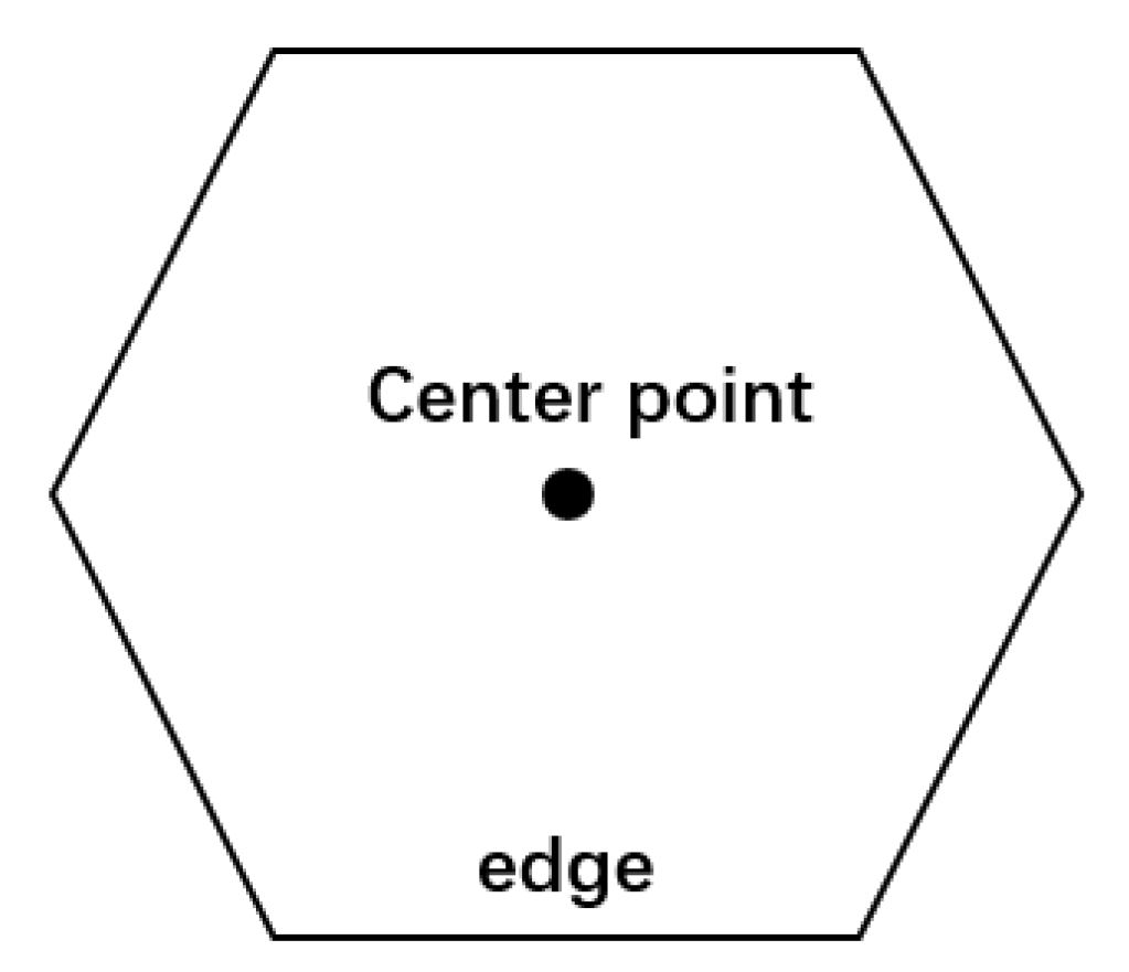
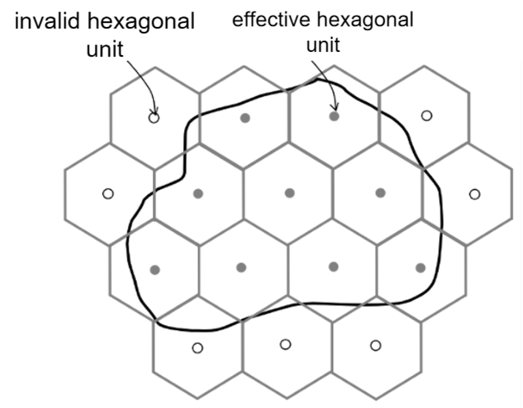
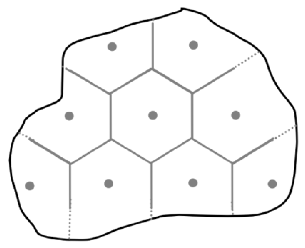
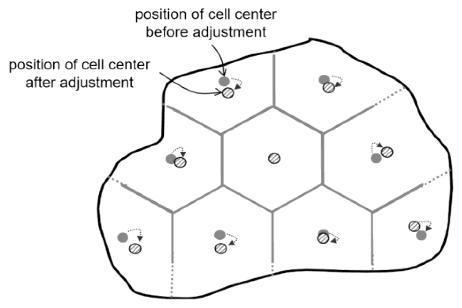
  • A dynamically adjusted region segmentation algorithm is proposed based on the construction of regular hexagons and a Voronoi diagram.
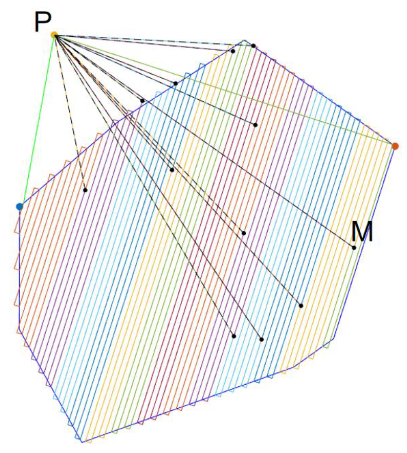
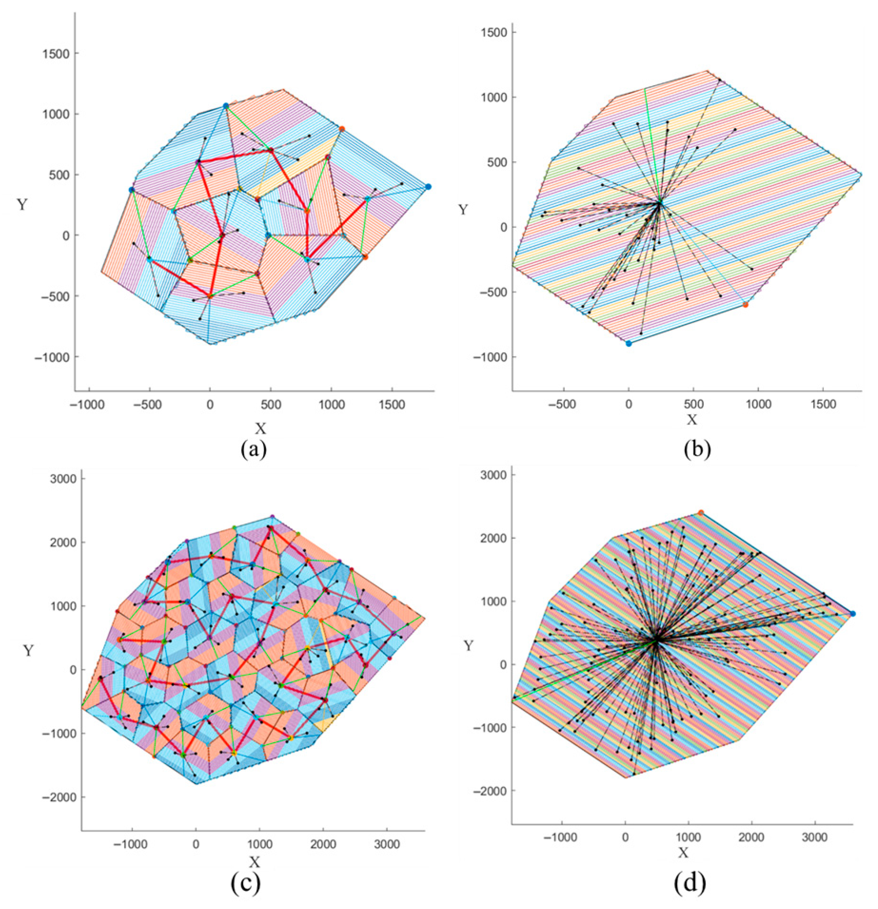
  • An ant colony optimization algorithm is adopted to generate the vehicle paths from the supply points for connecting each sub-area, and a zigzag coverage path method is utilized to ensure the UAV paths to fill the contours of each sub-area.
  • Simulation experiments are provided to verify the effectiveness and feasibility of the proposed vehicle–UAV collaboration method, and two comparative experiments are constructed to demonstrate that the proposed method excels at large-scale coverage path planning scenarios, and achieves a significant improvement in coverage efficiency.

2. Related Works

The collaboration model between vehicles and UAVs was first proposed by Murray and Chu [14] and has been widely used in reality, for purposes such as intelligence gathering, detection and surveillance of specific targets [15], parcel delivery [16] and circuit inspection [17]. Based on the roles of vehicles and UAVs in mission execution, vehicle–UAV cooperation problems can be categorized into four types:
  • Vehicle–UAV independent mode: Drones and vehicles perform their tasks independently without affecting each other. Fikar et al. [18] proposed a simulation and optimization based decision-support system to facilitate disaster relief coordination between private and relief organizations, in which the trucks and UAVs are adopted to transport the relief goods from transfer points to demand points, but more attention is paid to the coordination between the private and relief organizations. Marlin et al. [19] presented a dynamic vehicle routine problem with heterogeneous fleets to improve same-day delivery performance and proposed a policy function approximation based on geographical districting to decide whether an order is delivered by a drone or by a vehicle in the same-day context.
  • UAV-first mode: UAVs take the primary role in the mission, with vehicles acting as support vehicles. Tokekar et al. [20] studied an approximation algorithm for the traveling salesperson problem with neighborhoods to choose sampling locations from disks and generate a route to visit these locations while minimizing the sum of the travel and measurement times. Garone et al. [21] introduced cooperative mission planning for a class of carrier-vehicle system and presented a heuristic solution for cooperation between a ship and a helicopter to solve two mission planning problems: one involving visiting a list of points sequentially under the hypothesis that the takeoff/landing sequence is not determined a priori, and a second in which the visiting sequence of points is optimized. Mathew et al. [22] addressed the task scheduling and path planning problem for a team of cooperating vehicles performing autonomous deliveries while ensuring the quadrotor delivered items at all requested locations along the shortest cooperative route.
  • Vehicle-first model: The vehicle has a higher priority in the task, and the cooperative optimization problem mainly describes the objective function of the vehicle, with the UAV acting as an auxiliary tool. Savuran et al. [23] designed a solution based on the genetic algorithm and the nearest-neighbor heuristic to generate a route with minimization of total route length while ensuring take-off and land-on locations. Fawaz et al. [24] explored a UAV-based method to minimize the path availability’s dependence on vehicular density and cooperation while enhancing the availability of a connectivity path, as well as reducing the end-to-end package delivery delay.
  • Vehicle–UAV Collaboration Model: In this model, the vehicle and the UAV must work together, and one may need to wait for the other. Despite the high cost of collaboration, Poikonen et al. [25] and Wang et al. [26] demonstrated that the delivery time in the vehicle–UAV collaboration mode is usually less than that of using the vehicle alone. Campbell et al. [27] showed that using UAV-equipped trucks for cargo delivery saves about 10% to 40% of the transportation cost. Grocholsky et al. [28] constructed a model and algorithmic framework for vehicle and UAV collaboration for aerial and ground surveillance. DeFreitas et al. [29] optimized the initial solution using a stochastic variable domain heuristic and verified that the method works better in solving large-scale cases. Liu Yao et al. [30] modeled the effect of UAV load on its energy consumption and used a simulated annealing algorithm to solve a two-tier path planning problem for vehicle-mounted UAVs for collaborative distribution. Ropero et al. [31] proposed a method for exploring planetary surfaces based on a hybrid UGV–UAV system. Phan et al. [32] proposed a hierarchical UAV/ UGV platform.
These studies provide valuable strategies for solving the vehicle-mounted UAV path planning problem, but mainly focus on how to efficiently visit specific points rather than covering the whole area. The vehicle–UAV cooperation path planning method proposed in this paper is dedicated to solving this problem.

3. Coverage Path Planning Method Based on Vehicle–UAV Collaboration

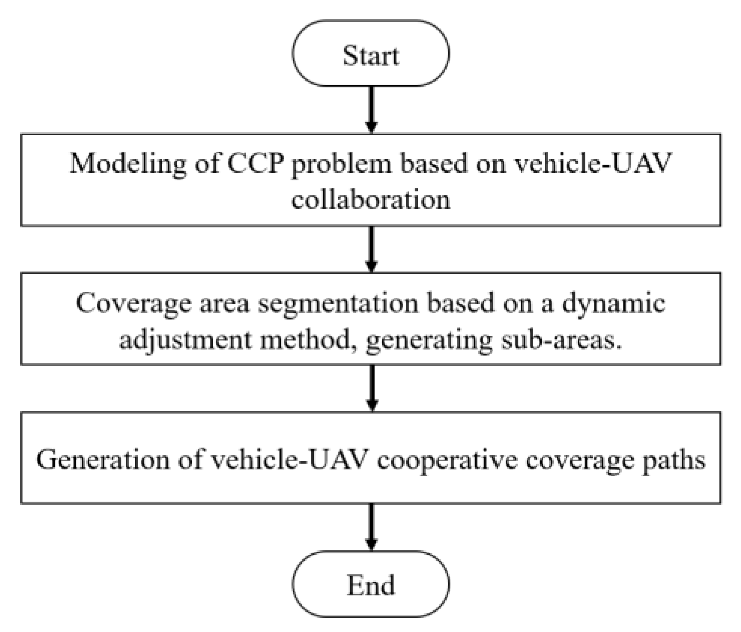
3.1. Overview of the Methodologies

Firstly, the vehicle–UAV collaboration system for coverage scanning path planning over large areas needs to be modeled. Based on the coverage area, the boundary contour needs be obtained, which will be used as a virtual coverage 2D map, and all the coverage path planning will be performed on this 2D map. The UAV energy model is also simply modeled. Secondly, inspired by the divide-and-conquer algorithm, a coverage area segmentation method based on dynamic adjustment is presented for dividing the large area into sub-areas with approximately equal sizes. All supply points are adjusted multiple times to ensure the points are located in the most reasonable position, and all sub-areas are adjusted again to ensure that the points within a sub-area have a shorter distance to the corresponding supply point. Thirdly, generation of vehicle–UAV cooperative coverage paths based on the sub-area contours and the supply points takes place. The vehicle path should traverse all supply points with the shortest possible length, and the UAV path should cover all sub-areas with path simplicity and operability. A flowchart of the proposed CCP method based on vehicle–UAV collaboration is shown in Figure 2.

3.2. Modeling of Coverage Path Planning Problem

In the CCP problem, the boundary contour of the coverage area is taken as a key consideration point for path planning. Note that, in practical coverage areas, like crop growth detection on farms and wilderness search and rescue, there would be various types of special terrain or constraints, such as hills, no-fly zones, etc., in the CCP problem. These issues that need to be considered can be reduced into a polygon region filling problem in 2D space. The boundary contour in the CCP problem is regarded as a polygon, which is indicated as C. For the sake of simplicity, the following modeling issues related to the CCP problem of UAVs will be described from the perspective of computer graphics.
The UAV energy model is a very complex research field, and the energy model calculation is closely related to various factors [13,33,34,35], such as flight speed, load changes, flight altitude, etc. Intuitively, the energy calculation for a UAV is positively correlated with the flight distance (i.e., flight path length). Thus, in order to simplify the energy model calculation for a UAV, the global length of the sweeping planning paths in a 3D map of mountainous terrain is used as the main energy model indicator.
For the paths in a 2D map, the traces of UAVs are described as a series of ordered coordinate points. Define the coverage path as Q, with the number of path points being q, then Q can be expressed as (1):
Q = x 1 , y 1 , x 2 , y 2 , , x q , y q
where ( x i , y i ) ,   i [ 1 , q ] . In addition, the energy consumption–cost function of a UAV based on path length is defined as (2).
H = i = 1 q 1 x i x i + 1 2 + y i y i + 1 2        
Another worthwhile issue is the work unit segmentation model problem for large- scale areas, which is related to the single UAV flight distance. It should be noted that, if the work unit area is divided into too-small areas, it will result in a sharp increase in the number of segmented work units, which will increase the burden on vehicle path planning. Conversely, if the partition work unit is too large, it will generate excessive UAV round-trip paths in each work unit, which is meaningless for the coverage mission and reduces the efficiency of the scanning coverage task. Therefore, the area of partition work units needs to be balanced, and it is assumed that only a small number of UAV flights are needed to complete the coverage task for the work units. Assuming that the coverage width of the UAV path is M, the total flight distance of a single UAV flight is L, and the number of UAV flights for the work unit is k, the area S of a work unit can be calculated according to (3). Regular polygons, such as triangles, squares, and hexagons, are very suitable for solving the problem of work area division, generating relatively uniform work units. Regular hexagons are adopted for the work unit partition problem. Taking the relationship between the area of a regular hexagon and its edges, the edge value a of a regular hexagon unit can be preliminarily calculated from (4), as shown in Figure 3.
S = L W k
a = 2 S 3 3

3.3. Coverage Area Segmentation Method Based on Dynamic Adjustment

In this subsection, a coverage area segmentation method based on dynamic adjustment is presented for dividing the large area into sub-areas with approximately equal sizes. The core idea of dynamic adjustment is to determine the positions of supply points through multiple adjustments, and all sub-areas are repeatedly adjusted to ensure that the points within each sub-area have a shorter distance to the corresponding supply point.
The coverage area segmentation method starts from the abovementioned regular hexagons. In the proposed coverage area segmentation method, the effectiveness of the hexagons is mainly determined based on the position of the center point. If the center point is located inside the polygon C of coverage area, then the hexagonal unit is valid, and vice versa: the hexagonal unit is invalid if the center point is located outside the polygon C, as shown in Figure 4.
These valid hexagons are retained, while invalid hexagons need to be removed and their adjacent hexagonal units need to be modified. Firstly, the edges of invalid hexagons are removed. For these valid but incomplete hexagons, if one endpoint in the remaining edge has no connection with other edge, the edge is called a single independent edge, and this edge needs to be extended to intersect with the polygon C to form a new edge. Thus, the extended edges, the partial polygon contour of C and the remaining edges together form the boundary of the modified hexagonal unit. Through the above process, the segmentation of the large coverage area is completed, and sub-areas and their corresponding contours can be generated, as shown in Figure 5.
Owing to the modification of incomplete hexagons, the original center also needs to be modified. The gravity position of these modified sub-areas is used to act as the new center point, according to (5), which is the classical polygon gravity formula.
C x = P i x n C y = P i y n
where (Pix,Piy) represents the points in the contour of polygon, the number of points is n and (Cx,Cy) indicates the new center of gravity. The modified center of each sub-area is illustrated in Figure 6. These centers of each sub-area act as the supply points.
In order to refine the segmentation, the sub-area generation method is further performed based on these modified supply points. A fundamental principle is to ensure that, compared to the distance to supply points in other sub-areas, the point located in the current sub-area has the shortest distance to the corresponding supply point. The points on the common edge between two sub-areas have equal distances to the two adjacent supply points.
Considering the above constraints, a further adjustment method based on a Voronoi diagram (VG) [36] needs to be performed on these sub-areas. Firstly, the supply points are used as the discrete points for the construction of the VG. Construction of Delaunay triangulation is carried out on these discrete points. The relationship between the construction of each triangle and its corresponding three discrete points is recorded. The circumcircle center of each triangle is calculated. Secondly, the adjacent three triangles that share the same edge with current triangle pTri need to be adjusted by traversing the triangle linked list. If the adjacent triangles exist, the circumcircle center of the adjacent triangle connects to the circumcircle center of triangle pTri, and the new added line is stored in the Voronoi edge linked list. Conversely, the outermost perpendicular ray will intersect with contour C of the coverage area, and the new edge generated from the perpendicular line is also added to the Voronoi edge linked list. Finally, the traversal process is finished, all the Voronoi edges are generated. By virtue of the abovementioned construction of the VG, the Voronoi edge divides the coverage area into a series of Voronoi units, and each Voronoi unit is regarded as a sub-area, as shown in Figure 7.
Through the above steps, all supply points will be adjusted multiple times to ensure the points are located in the most reasonable position, and all sub-areas are adjusted again to ensure that the points within a sub-area have a shorter distance to the corresponding supply point. The contours of these sub-areas and these supply points are the key factors for the generation of vehicle–UAV cooperative coverage paths.

3.4. Generation of Vehicle–UAV Cooperative Coverage Paths

Specifically, the vehicle needs to deliver the UAV to the vicinity of the target area, where the UAV is released, then the vehicle waits for the UAV to complete the scanning task in the sub-area. After the UAV returns to the vehicle platform, the vehicle replaces batteries and supplies for the UAV. Once the sub-area coverage is complete, the vehicle carries the UAV to the next sub-area until the entire large area is completed. Therefore, the vehicle and the UAV need a cooperative coverage path for coverage tasks for large areas, and more attention needs to be paid to the efficiency of vehicle movements and UAV flights.
With regard to vehicle movements, the requirement for vehicle path planning is to traverse all supply points with the shortest vehicle path. Essentially, the vehicle path planning problem in our research work can be approximately classified as a typical Traveling Salesman Problem (TSP). TSP is a classic combinatorial optimization problem that is significant in operations research and theoretical computer science. Due to the fact that the feasible solution to this problem is the complete arrangement of all vertices, as the number of vertices increases, a combinatorial explosion occurs, making it an NP-Complete problem.
It cannot be denied that, in practical applications, approximate solutions can generally meet the requirements of NPC problems. Therefore, an approximation solution is expected to find a near-optimal solution for TSP, providing a specific percentage of the optimal solution and requiring a reasonable time. In this research work, a classical ant colony optimization (ACO) algorithm [37] is adopted in the vehicle path planning method to guarantee a generated path with the shortest possible length. The Euclidean distance between two supply points is used as the weight of the connecting edge. Firstly, in the initial case, all supply points are inserted into a set, indicated by S. A new set V is created to store the points on the shortest path determined by the computation. A preset supply point is selected as the starting point P, and P is removed from the set S and then inserted into V. Secondly, another supply point is selected from the remaining set S to ensure this supply point has the shortest possible distance to the points within set V. Then, this set S and V are updated, and this supply point is removed from S and added to V accordingly. The above operations are repeated, and the vehicle path planning method ends when set S is completely empty, and all the supply points have been added to set V. Finally, the sequence of supply points recorded in set V represents the planning path of the vehicle, and it ensures the vehicle can traverse all supply points in the coverage are with the shortest possible route, as shown in Figure 8.
It is noted that, to some extent, the number of supply points generated for large areas may not be critical to the proposed vehicle–UAV collaboration CCP method. On the one hand, in practice, the vehicle path planning procedure is performed in advance. In other words, there is sufficient time for the ACO algorithm to generate vehicle paths. On the other hand, in the algorithm design of our research work, the number of supply points is approximately the same as the number of segmentation units. The number of segmentation units can be reduced by expanding the area of the sub-areas, resulting in a decrease in the number and scale of the supply points.
In terms of the path planning problem for UAVs in a large area, the requirement for the UAV is to complete the coverage task of the entire area in a divide-and-conquer manner. In each sub-area, the coverage path needs to integrate with the vehicle supply points, providing the benefits of improving efficiency in the CCP problem. The contour of the sub-area is adopted for generating the classic zigzag coverage path [38], which is illustrated in Figure 1. The zigzag coverage path ensures efficient coverage by the UAV, while maintaining path simplicity and operability.
Through the above steps, mixed paths can be generated from the proposed vehicle–UAV collaboration method, and provide the vehicle with the shortest-length path to traverse all supply points and the UAV with a coverage path with simplicity and path operability. The mixed paths are illustrated in Figure 9b. In each sub-area, the vehicle and the UAV cooperate to complete the power supply and the transfer of collected data, and travel together to the next sub-area.
It should be noted that the proposed vehicle–UAV collaboration method is suitable for a coverage area with relatively flat terrain features. By projecting this terrain onto a 2D plane, the obtained 2D polygons of the coverage area can be subjected to coverage path planning using the vehicle–UAV collaboration method proposed in this work. With regard to coverage areas containing spatial obstacles, such as signal towers in the wilderness, tall buildings outdoors, etc., to some extent, the following two approaches can be used to break through this constraint. On the one hand, the projection plane can be lifted to a certain height to ensure that these spatial obstacles disappear in the projection plane; on the other hand, an obstacle polygon can be placed inside the contour of the projection scanning area in advance, which means the internal area of the obstacle polygon is located outside of the coverage area; thus the coverage path would not be generated in the obstacle polygon.
Furthermore, the proposed vehicle–UAV collaboration method also provides the ability for collaboration between many vehicles and UAVs, which can improve the total efficiency of entire coverage areas. This is because the proposed CCP method provides a new mode to address the collaborative coverage problem between vehicles and UAVs, and generates the UAV paths in each sub-area and the vehicle paths for connecting all these sub-areas. In essence, these UAV paths and vehicle paths offer a collaborative from of sequential mode, which is suitable for single vehicles and single UAVs. From a programming perspective, these coverage tasks for sub-areas possess the characteristics of low coupling and strong independence. Thus, by virtue of the parallel model, the efficiency of overall coverage tasks can be improved. That is to say, the proposed method can be extended to many vehicles and UAVs. Since the entire vehicle path connects all these sub-areas and can be divided into several intervals based on the vertices (supply points) defined in the path, then these sub-areas related to the interval can be covered collaboratively by a combination of vehicles and UAVs. To some extent, there may be signal interference or signal delay issues in vehicle and drone control, but this is not the main focus of this research work.

4. Simulation and Discussion

The proposed large-area coverage path planning method based on vehicle–UAV collaboration proposed in this work has been implemented in MATLAB language, and all the results are rendered via the MATLAB plot function tool (2024a). In the simulation experiment, the proposed vehicle–UAV collaboration method was verified in two test cases. The two test cases were used for algorithm evaluation and validation in small- and large-area scenarios, respectively. The two polygons consist of a number of vertices generated within two square areas and are simulated in the virtual 2D map. The side lengths of the two squares are 3000 m and 6000 m, respectively. The flight speed of the UAV was set to 3.5 m/s. The coverage width of the UAV path was set to 20 m, the safe endurance time of the UAV under heavy load is assumed to be 2000 s, and the maximum number of UAV flights for the coverage task in a sub-area is set to four. Thus, the single flight distance of the UAV is 7000 m, and the appropriate area for coverage in a sub-area is about 32,000 m2.
The polygon contour is loaded into the proposed vehicle–UAV collaboration method, and the outputs consist of UAV paths and vehicle paths, and all the data related to this simulation experiment are illustrated in Figure 9a,c. The area enclosed by the outermost contour is the workspace of the CCP problem. From the simulation results, it can be seen that the polygon is reasonably divided into multiple sub-areas, ensuring that these sub-areas have an approximately equal area, and providing the vertices within sub-areas the benefit of the shortest distance to the supply point. The supply points in the coverage polygon are rendered with green circles. In each sub-area, the contour is filled with multiple, equally spaced zigzag path lines; each zigzag line indicates a single flight of the UAV and is rendered with a color. The blue dot, the orange dot and the black dot indicate the starting point, the ending point and the switching point, respectively. These colored zigzag path lines have equal lengths, ensuring that the UAV can complete the coverage task in the current sub-area with fewer supplies. The bold red lines in the figure denote the simulated traversal path of the vehicle, providing an efficient way to traverse the supply points of all sub-areas. From the simulation experiments, it can be concluded that the effectiveness and feasibility of the proposed large-area coverage path planning method based on vehicle–UAV collaboration can be verified.
In order to demonstrate the coverage efficiency advantage of the proposed vehicle–UAV collaboration method, two comparative experiments were conducted. The classic zigzag path filling algorithm, based entirely on the UAV, was implemented using MATLAB language and directly applied on the same polygons. For the fairness of the experiments, the gravity position was also selected as the supply point of the entire polygon. Based on the preset supply point and the single flight distance of the UAV, the coverage paths were generated, as shown in Figure 9b and Figure 9d, respectively. From the figure, it can be seen that the generated coverage paths of the UAV contain a large number of switching points, which is caused by the UAV constraint of short endurance under heavy loads. The flight segments connecting these switching points and the supply points are the main factors affecting UAV coverage efficiency over large areas.
The results of the total coverage path lengths in the two comparative experiments are summarized in Table 1. Through comparative analysis of the statistical results, in the coverage problem of the small area test case, the classic zigzag coverage path based on UAV only has a total length of 224,943 m, while the proposed method generates a total coverage path length of 202,626 m, which consists of a UAV flight path length of 198,603 m and a vehicle travel path length of 4023 m, and achieves a 9.92% path saving advantage. However, in the coverage problem of the large area test case, the classic zigzag coverage path generated a total path length of up to 1,127,467 m, while the total path length generated by the proposed method based on vehicle–UAV collaboration was only 820,678 m. The proposed method can achieve up to a 27.21% path saving advantage. The vehicle–UAV collaboration-based coverage path method proposed in this paper has significant advantages in reducing the round-trip path length of a UAV. It can be obviously concluded that the proposed method excels at large-scale coverage path planning scenarios, and achieves a significant improvement in coverage efficiency.
It is noted that the mixed paths are described using two-dimensional coordinates, while the actual collaborative trajectory of drones and vehicles is three-dimensional. The height information of vertices in the 2D path is missing, but this can be calculated through interpolation of the digital elevation model of the coverage area. Additionally, the generated trajectory can be saved as a KML (Keynote markup language) file. As KML is a universal file format, the planned coverage trajectory can be used for data exchange in almost any ground control station, which is beneficial for improving the compatibility of the proposed vehicle–UAV collaboration method.

5. Conclusions

In this paper, a coverage path planning method based on vehicle–UAV collaboration is proposed for large areas. The core idea of the proposed method is adopting a divide-and-conquer strategy to divide a large area into small areas, and then completing efficient coverage scanning tasks through the collaborative cooperation of vehicles and UAVs. The supply points are generated and adjusted based on the construction of regular hexagons and a Voronoi diagram, and the segmentation and adjustment of sub-areas are also achieved during this procedure. The vehicle paths are constructed based on the classical ACO algorithm, providing an efficient way to traverse all supply points within the coverage area. The classic zigzag coverage path method is adopted to fill the contours of each sub-area, and the UAV paths collaborate with vehicle supply points using few switching points. The simulation experiments verify the effectiveness and feasibility of the proposed vehicle–UAV collaboration coverage path planning method, and the comparative experiments demonstrate that the proposed method excels at large-scale coverage path planning scenarios, and achieves a significant improvement in coverage efficiency.

Author Contributions

Conceptualization, methodology, N.Z. and Q.Z.; software, B.Z.; validation, B.Z., J.F. and L.Y.; formal analysis, investigation, C.G.; resources, N.Z.; data curation, Q.Z.; writing—original draft preparation, writing—review and editing, visualization, N.Z. and B.Z.; supervision, Q.Z.; funding acquisition, Q.Z. All authors have read and agreed to the published version of the manuscript.

Funding

This research was supported by the Program of Song Shan Laboratory (included in the management of Major Science and Technology Program of Henan Province, Grant No. 221100211000-01).

Institutional Review Board Statement

Not applicable.

Informed Consent Statement

Not applicable.

Data Availability Statement

The original contributions presented in this study are included in the article. Further inquiries can be directed to the corresponding author.

Acknowledgments

Thanks to the anonymous reviewers for their thorough review and their instructive comments and suggestions.

Conflicts of Interest

The authors declare no conflicts of interest.

Abbreviations

The following abbreviations are used in this manuscript:
UAVUnmanned Aerial Vehicle
CCPCoverage Path Planning
VGVoronoi Diagram
TSPTraveling Salesman Problem
ACOAnt Colony Optimization
KMLKeynote markup language
3DThree Dimensional
2DTwo Dimensional

References

  1. Hashim, H.A. Advances in UAV avionics systems architecture, classification and integration: A comprehensive review and future perspectives. Results Eng. 2024, 25, 103786. [Google Scholar] [CrossRef]
  2. Barazzetti, L.; Remondino, F.; Scaioni, M. Extraction of accurate tie points for automated pose estimation of close-range blocks. In International Archives of the Photogrammetry, Remote Sensing and Spatial Information Sciences; ISPRS Archives: Saint-Mandé, France, 2010; Volume 38. [Google Scholar]
  3. Gao, H.; Yu, Y.; Huang, X.; Song, L.; Li, L.; Li, L.; Zhang, L. Enhancing the localization accuracy of UAV images under GNSS denial conditions. Sensors 2023, 23, 9751. [Google Scholar] [CrossRef] [PubMed]
  4. Lucieer, A.; Turner, D.; King, D.H.; Robinson, S.A. Using an unmanned aerial vehicle (UAV) to capture micro-topography of antarctic moss beds. Int. J. Appl. Earth Obs. Geoinf. 2014, 27, 53–62. [Google Scholar] [CrossRef]
  5. Ahmed, N.; Pawase, C.J.; Chang, K. Distributed 3-d path planning for multi-UAVs with full area surveillance based on particle swarm optimization. Appl. Sci. 2021, 11, 3417. [Google Scholar] [CrossRef]
  6. Pérez-González, A.; Benítez-Montoya, N.; Jaramillo-Duque, Á.; Cano-Quintero, J.B. Coverage path planning with semantic segmentation for UAV in PV plants. Appl. Sci. 2021, 11, 12093. [Google Scholar] [CrossRef]
  7. Valente, J.; Sanz, D.; Del Cerro, J.; Barrientos, A.; de Frutos, M.Á. Near-optimal coverage trajectories for image mosaicing using a mini quad-rotor over irregular-shaped fields. Precis. Agric. 2013, 14, 115–132. [Google Scholar] [CrossRef]
  8. Guo, F.; Gao, W. Batch reconstruction from UAV images with prior information. Acta Autom. Sin. 2013, 39, 834–845. [Google Scholar] [CrossRef]
  9. Casbeer, D.W.; Kingston, D.B.; Beard, R.W.; McLain, T.W. Cooperative forest fire surveillance using a team of small unmanned air vehicles. Int. J. Syst. Sci. 2006, 37, 351–360. [Google Scholar] [CrossRef]
  10. Delmerico, J.; Mintchev, S.; Giusti, A.; Gromov, B.; Melo, K.; Horvat, T.; Cadena, C.; Hutter, M.; Ijspeert, A.; Floreano, D.; et al. The current state and future outlook of rescue robotics. J. Field Robot. 2019, 36, 1171–1191. [Google Scholar] [CrossRef]
  11. Cong, W.; Yi, H.; Yu, F.; Chen, J.; Chen, X.; Xu, F. An improved pied kingfisher optimizer for maritime UAV path planning. Appl. Sci. 2024, 14, 11816. [Google Scholar] [CrossRef]
  12. Han, D.; Yu, Q.; Jiang, H.; Chen, Y.; Zhu, X.; Wang, L. Three-dimensional path planning for post-disaster rescue UAV by integrating improved grey wolf optimizer and artificial potential field method. Appl. Sci. 2024, 14, 4461. [Google Scholar] [CrossRef]
  13. Ahmed, G.; Sheltami, T.; Ghaleb, M.; Hamdan, M.; Mahmoud, A.; Yasar, A. Energy-efficient internet of drones path-planning study using meta-heuristic algorithms. Appl. Sci. 2024, 14, 2418. [Google Scholar] [CrossRef]
  14. Murray, C.C.; Chu, A.G. The flying sidekick traveling salesman problem: Optimization of drone-assisted parcel delivery. Transp. Res. Part C Emerg. Technol. 2015, 54, 86–109. [Google Scholar] [CrossRef]
  15. Manyam, S.; Casbeer, D.; Sundar, K. Path planning for cooperative routing of air-ground vehicles. In Proceedings of the 2016 American Control Conference (ACC), Boston, MA, USA, 6–8 July 2016. [Google Scholar]
  16. Agatz, N.; Bouman, P.; Schmidt, M. Optimization approaches for the traveling salesman problem with drone. Transp. Sci. 2018, 52, 965–981. [Google Scholar] [CrossRef]
  17. Deng, C.; Wang, S.; Huang, Z.; Tan, Z.; Liu, J. Unmanned aerial vehicles for power line inspection: A cooperative way in platforms and communications. J. Commun. 2014, 9, 687–692. [Google Scholar] [CrossRef]
  18. Fikar, C.; Gronalt, M.; Hirsch, P. A decision support system for coordinated disaster relief distribution. Expert Syst. Appl. 2016, 57, 104–116. [Google Scholar] [CrossRef]
  19. Ulmer, M.W.; Thomas, B.W. Same-day delivery with heterogeneous fleets of drones and vehicles. Networks 2018, 72, 475–505. [Google Scholar] [CrossRef]
  20. Tokekar, P.; Vander Hook, J.; Mulla, D.; Isler, V. Sensor planning for a symbiotic UAV and UGV system for precision agriculture. IEEE Trans. Robot. 2016, 32, 1498–1511. [Google Scholar] [CrossRef]
  21. Garone, E.; Naldi, R.; Casavola, A.; Frazzoli, E. Cooperative mission planning for a class of carrier-vehicle systems. In Proceedings of the 49th IEEE Conference on Decision and Control (CDC), Atlanta, GA, USA, 15–17 December 2010. [Google Scholar]
  22. Mathew, N.; Smith, S.; Waslander, S. Planning paths for package delivery in heterogeneous multirobot teams. IEEE Trans. Autom. Sci. Eng. 2015, 12, 1298–1308. [Google Scholar] [CrossRef]
  23. Savuran, H.; Karakaya, M. Route optimization method for unmanned air vehicle launched from a carrier. Lect. Notes Softw. Eng. 2015, 3, 279. [Google Scholar] [CrossRef]
  24. Fawaz, W.; Atallah, R.; Assi, C.; Khabbaz, M. Unmanned aerial vehicles as store-carry-forward nodes for vehicular networks. IEEE Access 2017, 5, 23710–23718. [Google Scholar] [CrossRef]
  25. Poikonen, S.; Wang, X.; Golden, B. The vehicle routing problem with drones: Extended models and connections. Networks 2017, 70, 34–43. [Google Scholar] [CrossRef]
  26. Wang, X.; Poikonen, S.; Golden, B. The vehicle routing problem with drones: Several worst-case results. Optim. Lett. 2017, 11, 679–697. [Google Scholar] [CrossRef]
  27. Sweeney, D.C.; Campbell, J.F.; Zhang, J. Strategic design for delivery with trucks and drones. Supply Chain Anal. Rep. SCMA 2017, 47–55. Available online: https://www.updwg.org/wp-content/uploads/2019/05/StrategicDesignforDeliverywithDronesandTrucks_4-17-17_SCMA-2017-0201.pdf (accessed on 10 December 2024).
  28. Grocholsky, B.; Keller, J.; Kumar, V.; Pappas, G. Cooperative air and ground surveillance. IEEE Robot. Autom. Mag. 2006, 13, 16–25. [Google Scholar] [CrossRef]
  29. de Freitas, J.C.; Penna, P.H.V. A randomized variable neighborhood descent heuristic to solve the flying sidekick traveling salesman problem. Electron. Notes Discret. Math. 2018, 66, 95–102. [Google Scholar] [CrossRef]
  30. Liu, Y.; Liu, Z.; Shi, J.; Wu, G.; Pedrycz, W. Two-echelon routing problem for parcel delivery by cooperated truck and drone. IEEE Trans. Syst. Man Cybern. Syst. 2021, 51, 7450–7465. [Google Scholar] [CrossRef]
  31. Ropero, F.; Muñoz, P.; R-Moreno, M.D. TERRA: A path planning algorithm for cooperative UGV–UAV exploration. Eng. Appl. Artif. Intell. 2019, 78, 260–272. [Google Scholar] [CrossRef]
  32. Phan, C.; Liu, H. A cooperative UAV/UGV platform for wildfire detection and fighting. In Proceedings of the 2008 Asia Simulation Conference—7th International Conference on System Simulation and Scientific Computing, Beijing, China, 10–12 October 2008. [Google Scholar]
  33. Cabreira, T.; Franco, C.; Ferreira, P.; Buttazzo, G. Energy-aware spiral coverage path planning for UAV photogrammetric applications. IEEE Robot. Autom. Lett. 2018, 3, 3662–3668. [Google Scholar] [CrossRef]
  34. Nagy, I.; Laufer, E. Energy-optimized 3d path planning for unmanned aerial vehicles. Appl. Sci. 2024, 14, 6988. [Google Scholar] [CrossRef]
  35. Jung, S. Development of path planning tool for unmanned system considering energy consumption. Appl. Sci. 2019, 9, 3341. [Google Scholar] [CrossRef]
  36. Aurenhammer, F. Voronoi diagrams—A survey of a fundamental geometric data structure. ACM Comput. Surv. 1991, 23, 345–405. [Google Scholar] [CrossRef]
  37. Song, Q.; Zhao, Q.; Wang, S.; Liu, Q.; Chen, X. Dynamic path planning for unmanned vehicles based on fuzzy logic and improved ant colony optimization. IEEE Access 2020, 8, 62107–62115. [Google Scholar] [CrossRef]
  38. Ajaj, R.M.; Saavedra Flores, E.I.; Friswell, M.I.; Allegri, G.; Woods, B.K.S.; Isikveren, A.T.; Dettmer, W.G. The zigzag wingbox for a span morphing wing. Aerosp. Sci. Technol. 2013, 28, 364–375. [Google Scholar] [CrossRef]
Figure 1. Schematic diagram of UAV coverage path planning based on multiple flights for a large area.
Applsci 15 01247 g001
Figure 2. Flowchart of the proposed vehicle–UAV collaboration CCP method.
Applsci 15 01247 g002
Figure 3. Schematic diagram of a regular hexagon.
Applsci 15 01247 g003
Figure 4. Schematic of hexagonal grid coverage results.
Applsci 15 01247 g004
Figure 5. Coverage area segmentation and sub-area generation.
Applsci 15 01247 g005
Figure 6. The modification of center positions for incomplete hexagons.
Applsci 15 01247 g006
Figure 7. The modification of sub-area adjustment based on Voronoi Diagram.
Applsci 15 01247 g007
Figure 8. Schematic of the vehicle path planning method based on the ACO algorithm.
Applsci 15 01247 g008
Figure 9. Simulation experiment results using different methods. (a,c) are the outputs of the proposed vehicle–UAV collaboration method; (b,d) are the generates of the conventional zigzag path method.
Applsci 15 01247 g009
Table 1. Statistical results of comparative experiments on different coverage path methods.
Coverage Path Planning MethodsTotal Path Length (m)
Small Area CaseLarge Area Case
The Proposed Coverage Path Planning Method Based on Vehicle–UAV Collaboration202,626820,678
The Classic Zigzag Coverage Path Planning Method Based Entirely on UAV224,9431,127,467
Disclaimer/Publisher’s Note: The statements, opinions and data contained in all publications are solely those of the individual author(s) and contributor(s) and not of MDPI and/or the editor(s). MDPI and/or the editor(s) disclaim responsibility for any injury to people or property resulting from any ideas, methods, instructions or products referred to in the content.

