Article

Adaptive Impedance Control of a Human–Robotic System Based on Motion Intention Estimation and Output Constraints

1
School of Electrical Engineering, Southwest Jiaotong University, Chengdu 610031, China
2
School of Electrical Engineering and Electronic Information, Xihua University, Chengdu 610039, China
*
Author to whom correspondence should be addressed.
Appl. Sci. 2025, 15(3), 1271; https://doi.org/10.3390/app15031271
Submission received: 28 December 2024 / Revised: 18 January 2025 / Accepted: 23 January 2025 / Published: 26 January 2025

Abstract

:
The rehabilitation exoskeleton represents a typical human–robot system featuring complex nonlinear dynamics. This paper is devoted to proposing an adaptive impedance control strategy for a rehabilitation exoskelton. The patient’s motion intention is estimated online by the neural network (NN) to cope with the intervention of the patient’s subjective motor awareness in the late stage of rehabilitation training. Due to the differences in impedance parameters for training tasks in individual patients and periods, the least square method was used to learn the impedance parameters of the patient. Considering the uncertainties of the exoskeleton and the safety of rehabilitation training, an adaptive neural network impedance controller with output constraints was designed. The NN was applied to approximate the unknown dynamics and the barrier Lyapunov function was applied to prevent the system from violating the output rules. The feasibility and effectiveness of the proposed strategy were verified by simulation.

1. Introduction

Recent research has demonstrated that device-assisted therapy is the primary approach for restoring physical functions in patients with physical disabilities [1]. The synchronization of motor intention with corresponding physical action is a critical determinant in optimizing the efficacy of rehabilitation exercises [2,3]. Rehabilitation exoskeletons have received widespread attention for their ability to address the inherent limitations of traditional manual rehabilitation training, including insufficient precision in motion control, the shortage of rehabilitation therapists, and the high treatment costs [4,5]. However, in the rehabilitation training stage, a lower limb rehabilitation exoskeleton is difficult to effectively comply with the patient, and there are many challenges in the interaction between the exoskeleton and the patient [6,7].
For the above reasons, two methods to achieve compliance control in rehabilitation exoskeletons are proposed [8,9]. The first is force/position hybrid control, which realizes the conflict-free control of position and force, but its limitation is that the human–robot interaction force is regarded as a disturbance [10]. The second solution is impedance control, which was first proposed by Hogan [11]. The primary goal of impedance control is to regulate the dynamic force/position relationship in human–robot interaction systems, enabling robots to emulate human biomechanics, as well as to enhance the flexibility and functional performance of applications like rehabilitation exoskeletons [12,13,14]. For its good robustness and availability, impedance control has been widely developed [15,16]. A neural network-based impedance control framework for real-time dynamic adjustment of impedance parameters is proposed in [17], improving adaptability and interaction performance. In [18], an event-triggered impedance controller is designed to enable precise trajectory tracking in interactive environments.
In the later period of lower limb rehabilitation, the patient has strong autonomous motor awareness and motor ability. At this stage, the rehabilitation task is led by the patient, and the exoskeleton is used as a collaborative device to assist training. If the exoskeleton does not know the patient’s movement intention, it will be treated as a load and cause a loss of strength in the affected limb, affecting the effectiveness of rehabilitation training. Therefore, it is important to estimate the motion intention of the affected limb. Many algorithms for estimating human motion intention have been proposed [19,20,21]. In [22], the electroencephalogram is utilized to infer motion intentions, enabling accurate rehabilitation trajectory tracking. In [23], motion intentions were estimated using input data and Deep Learning algorithms, facilitating precise and reliable control of lower limb exoskeletons.
To adapt to the changing rehabilitation needs of impaired limbs, achieving real-time adjustment of the desired impedance of the exoskeleton remains a key challenge in lower limb rehabilitation training. An online impedance controller is designed in [24] using a novel adaptive method for parameter estimation, achieving real-time control. Ref. [25] adopts reinforcement learning with an actor–critic algorithm to obtain the optimal value of impedance parameters for robot contact tasks. An iterative learning method is proposed in [26], where stiffness and viscosity parameters in the target impedance model can be adjusted. In [27], an estimation method of human upper limb impedance for a 2-DOF assembly robot with nonlinear friction is proposed. The researchers in [28] employed the recursive least squares algorithm to perform online real-time parameter estimation, effectively satisfying the system’s real-time control requirements.
Ensuring the safety of patients is essential during human–exoskeleton interaction, particularly in the scenario of lower limb rehabilitation training. Aiming at this problem, the application of output constraint in exoskeletons [29,30,31] has attracted wide attention. Using the barrier Lyapunov function (BLF) is an effective method to constrain the output of an exoskeleton in joint space or task space. In [32], an output constraints controller is designed based on BLF, and it is ensured that there is no violation of the constraint rules. In [33], time-varying output constraints are considered. In [34], a pioneer output constraint controller is proposed for strictly feedback nonlinear systems. However, in the real world, due to factors such as measurement noise, it is impossible to obtain an accurate dynamic model of the exoskeleton. The uncertainty and complexity of the control system varies from patient to patient, so it is important to design a controller that meets the requirements of the unknown dynamics of the exoskeleton. Neural networks (NNs) are extensively applied to the control of uncertain, nonlinear, and complex systems due to their outstanding ability to approximate functions with high levels of accuracy [35,36,37,38,39]. Ref. [40] employed a neural network for disturbance estimation, significantly enhancing the robustness of the control approach. In [41], an adaptive NN is used to approximate the unknown nonlinearity of the hydraulic actuator of a hydraulic knee exoskeleton.
Based on the above discussion, this paper attempts to solve the problem of exoskeleton impedance control affected by patients’ subjective motor awareness in the later stage of lower limb rehabilitation. At the same time, the motion intention of the patient and the impedance learning of the exoskeleton were considered to improve the effect of rehabilitation training. An adaptive impedance control method combining neural networks and output constraints is proposed for dealing with the problem of human–robot interaction. The main contributions of this paper are as follows:
(1)
Compared with the existing impedance control methods in [12,15], which use a predefined trajectory for the exoskeleton, this paper proposes a novel neural network-based motion intention estimation method for human–robot interaction, where the exoskeleton is able to actively interact with the patient.
(2)
The impedance control of the exoskeleton in [16,17,18] cannot deal with the problem of output constraint. This paper incorporated the barrier Lyapunov function to construct the controller, where the output constraint is well addressed.
(3)
In this paper, an RBFNN is used to compensate for the uncertainties in the exoskeleton dynamics, further improving the accuracy of the system. Additionally, strict stability analysis is carried out to ensure the effectiveness of the rehabilitation training.
The structure of this paper is as follows. In Section 2, the dynamics of a lower limb rehabilitation exoskeleton is constructed and analyzed, and impedance control objectives are introduced. The algorithms of human motion intention estimation and impedance learning are designed and analyzed in Section 3. Under the output constraints, a NN-based adaptive impedance controller is designed, and the stability of the system is analyzed. In Section 4, the feasibility and effectiveness of the parameter learning and control algorithm are verified by numerical simulation. In Section 5, the conclusion is given.

2. Preliminaries

2.1. System Dynamics

The dynamic model of a lower limb rehabilitation exoskeleton joint is described as
M ( ζ ) ζ ¨ + C ( ζ , ζ ˙ ) ζ ˙ + G ( ζ ) + τ d i s = τ + f
where ζ n is the joint position vector, the positive definite symmetric matrix M ( ζ ) n × n represents the bounded inertia matrix, C ( ζ , ζ ˙ ) n denotes the bounded centripetal and Coriolis matrix, and G ( ζ ) n is the bounded gravitational vector. τ d i s n is the unmodeled disturbances of the exoskeleton, and f n represents the contact torque between the patient and the exoskeleton. τ n denotes the input torque.
Property 1
([1]). M ˙ ( ζ ) 2 C ( ζ , ζ ˙ ) is a skew-symmetric matrix, that is, T ( M ˙ ( ζ ) 2 C ( ζ , ζ ˙ ) ) = 0 , n .
Assumption 1.
The unmodeled disturbances of the exoskeleton τ d i s are bounded, and there exists a constant τ ¯ d i s that satisfies
| | τ d i s | | < τ ¯ d i s
The aim of this paper is to devise an adaptive impedance control law, which is based on motion intention estimation, for lower limb exoskeletons during the later stage of rehabilitation. This control law is intended to enable ζ to track the desired joint angles ζ d while ensuring the safety of the system.
The ζ d satisfies the following expected impedance model:
M d ( ζ ¨ ζ ¨ d ) + C d ( ζ ˙ ζ ˙ d ) + G d ( ζ ζ d ) = f
where f is a known quantity, and the positive definite diagonal matrices M d , C d , G d n × n denote the desired inertia, the damping, and the stiffness matrices, respectively.
In the predefined task, the desired trajectory of the rehabilitation exoskeleton is available for the controller design. However, in this paper, the ζ d is unknown and is determined by the consciousness of human autonomous motion.
Thus, the impedance model (3) is rewritten as
M d ( ζ ¨ ζ ^ ¨ H ) + C d ( ζ ˙ ζ ^ ˙ H ) + G d ( ζ ζ ^ H ) = f
where ζ ^ H is an estimate of the human motion intention ζ H , which will be given later.

2.2. Human Limb Model

The dynamics model of human motion intention ζ H is defined by [42]
M H ζ ¨ C H ζ ˙ + G H ( ζ H ζ ) = f
where the mass M H , damping C H , and spring G H are diagonal matrices.
As mentioned earlier, in human limb models, the mass matrix is usually ignored [43]. Therefore, (5) is rewritten as
C H ζ ˙ + G H ( ζ H ζ ) = f
Note that human impedance C H and G H are unknown functions with respect to the state of the system, so ζ H cannot be obtained by (6). However, ζ H can be expressed as a function of f, the actual position ζ , and the velocity ζ ˙ , that is,
ζ H = Y ( ζ , ζ ˙ , f )
where Y ( · ) is an unknown nonlinear function, which needs to be estimated.
Remark 1.
In fact, the impedance of a patient’s affected limb will change due to their different needs during rehabilitation training, making it difficult to estimate ζ ^ H .
In the actual training task, lower limb rehabilitation training is divided into two stages. In the first stage, the patient has a strong autonomous movement ability to play a leading role, and the exoskeleton is used as an auxiliary means. Therefore, it is necessary to reduce the impedance parameters and improve the flexibility of the system. In the second stage, the patient ’s ability to move autonomously is reduced due to the muscle fatigue of the affected limb. At this time, it is necessary to regulate the impedance parameters to ensure that the positioning accuracy of the joint trajectory is not affected by external interference and to ensure the effectiveness of rehabilitation training. In addition, the impedance parameters required for rehabilitation training vary from patient to patient. Inspired by this reason, the impedance parameter regulation laws are designed as
C ^ H + C d = C ¯ G ^ H + G d = G ¯
where C ¯ , G ¯ n are given positive parameters, and C ^ H and C ^ H are estimations of C H and G H , respectively, which will be given later.

3. Controller Design

In this section, the NN-based tracking control method is given by designing the motion intention estimation method and impedance learning method combined with BLF. The control structure is shown in Figure 1.

3.1. NN-Based Motion Intention Estimation

Radial basis function neural networks (RBF NNs) are employed for motion intention estimation. The continuous function Φ ( W , ħ ) can be represented through the usage of an RBFNN as follows [44]:
Φ ( W , ħ ) = W T S ( ħ )
where W is the adjustable weight vector and S ( ħ ) p is the basis function, which is described as
W = w 11 w 21 w r 1 w 12 w 22 w r 2 w 1 p w 2 p w r p S ( ħ ) = 1 ( ħ ) , 2 ( ħ ) , . . . , p ( ħ ) T j ħ = exp ħ μ j T ħ μ j η j 2
where ħ Ω ħ R m is the input of the NN, r represents the number of output neurons in the NN, p is the number of NN nodes, μ j = μ j , 1 , μ j , 1 , , μ j , m T is the center of the receptive field, and η is the width of the Gaussian function.
Using (9), ζ H , i and its estimation ζ ^ H , i are given as
ζ H , i = Θ ^ i T δ i ( η ¯ i ) + ε i ζ ^ H , i = Θ ^ i T δ i ( η ¯ i )
where ( · ) i ( i = 1 , 2 , , n ) is the ith component of ( · ) , η ¯ i = [ f i T , ζ i T , ζ ˙ i T ] T , δ i ( · ) is the radial basis function, and Θ ^ i and ε i denote the estimated weight and the estimation error, respectively.
We define the cost function as
E M , i = 1 2 f i 2
From the above analysis, if the interaction force between the patient and the exoskeleton can be minimized, it means that the rehabilitation exoskeleton can track the predetermined position determined by the patient’s motion intention. Thus, the adaptive law is selected as
Θ ^ ˙ i = β i E M , i Θ ^ i = β i E M , i f i f i ζ ^ H , i ζ ^ H , i Θ ^ i
where the partial derivatives E M , i f i , f i ζ ^ H , i , and ζ ^ H , i Θ ^ i are given as
E M , i f i = f i , f i ζ ^ H , i = ψ H , i , ζ ^ H , i Θ ^ i = δ i η ¯ i
Then, (12) is rewritten as
Θ ^ ˙ i = β i f i ψ H , i δ i ( η ¯ i ) = γ i β i δ i ( η ¯ i )
where β i is a positive constant and is absorbed by γ i together with ψ H , i . There is
Θ ^ i = Θ ^ i ( 0 ) γ i 0 t [ f i ( w ) δ i ( η ¯ i ( w ) ) ] d w
Then, the human motion intention ζ ^ H , i is obtained with (10) and (15).

3.2. Human Impedance Learning

In order to regulate the impedance parameter matrices of the exoskeleton based on the regulating mechanism (8), the learning law of C ^ H and G ^ H is obtained using the least square (LS) method in this section.
We define e = ζ ^ H ζ , and (6) is rewritten as
C ^ H ζ ˙ + G ^ H e = f ^
where f ^ is the estimate of measurable f.
We consider the following cost function:
E L , i = ı = 1 N f i ı f ^ i ı 2
where ı denotes the sampling number.
We take the partial derivatives of E L , i with respect to C H and G H , which are zero; there is
E L , i C H = 0 , E L , i G H = 0
Then, we have
ı = 1 N 2 C ^ H ζ ˙ i ı + G ^ H e i ı f i ı ζ ˙ i ı = 0 ı = 1 N 2 C ^ H ζ ˙ i ı + G ^ H e i ı f i ı e i ı = 0
that is
C ^ H ı = 1 N ζ ˙ i ı 2 + G ^ H ı = 1 N ζ ˙ i ı e i ı ı = 1 N ζ ˙ i ı f i ı = 0 C ^ H ı = 1 N ζ ˙ i ı e i ı + G ^ H ı = 1 N e i ı 2 ı = 1 N e i ı f i ı = 0
The tuning law of C ^ H ( t ) and G ^ H ( t ) is given as
C ^ H G ^ H = ı = 1 N ζ ˙ i ı 2 ı = 1 N ζ ˙ i ı e i ı ı = 1 N e i ı ζ ˙ i ı ı = 1 N e i ı 2 1 ı = 1 N ζ ˙ i j f i ı ı = 1 N e i ı f i ı
We define s as the sampling number at time t, and S T is the sampling interval in a sampling time period T. We have
C ^ H t G ^ H t = ı = 1 s ζ ˙ i ı 2 ı = 1 s ζ ˙ i ı e i ı ı = 1 s e i ı ζ ˙ i ı ı = 1 s e i ı 2 1 ı = 1 s ζ ˙ i ı f i ı ı = 1 s e i ı f i ı s S T
In order to ensure the positive definite symmetry of C ^ H ( t ) and G ^ H ( t ) , the symmetric positive definiteness matrices C ^ H and G ^ H are chosen by the Frobenius norm as the nearest values for C ^ H and G ^ H . Thus, there is
C ^ H = A + P 2 , A = C ^ H + C ^ H T 2 G ^ H = B + Y 2 , B = G ^ H + G ^ H T 2
where A = L P , B = R Y , L T L = I , R T R = I , and I is the identity matrix.

3.3. Output Constraints Tracking Control

In the rehabilitation training process, it is necessary to ensure the safety of lower limb rehabilitation training as shown in Figure 2. Therefore, the system output needs to meet the following constraints:
κ ̲ c ( t ) < ζ t < κ ¯ c ( t ) , t 0
where κ ̲ c ( t ) and κ ¯ c ( t ) are known time-varying functions.
We define the bounds of ζ as
κ a ( t ) = ζ d ( t ) κ ̲ c ( t )
κ b ( t ) = κ ¯ c ( t ) ζ d ( t )
In the following, the control law is designed in two cases.

3.3.1. Model-Based (MB) Impedance Control

Firstly, the control design with known system parameters is considered. We define the tracking error as z 1 = ζ ( t ) ζ d ( t ) , and a new assistant error variable as z 2 = ζ ˙ ( t ) χ ( t ) , where χ ( t ) = [ χ 1 ( t ) , χ 1 ( t ) , · · · , χ n ( t ) ] T is an assistant vector to be defined later. From Equation (1), z ˙ 2 is given as
z ˙ 2 = M 1 ( ζ ) [ τ + f τ d i s C ( ζ , ζ ˙ ) ζ ˙ G ( ζ ) ] χ ˙
We consider the following BLF:
V 1 ( t ) = i = 1 n ϑ i 2 ln κ b , i 2 ( t ) κ b , i 2 ( t ) z 1 , i 2 ( t ) + 1 ϑ i 2 ln κ a , i 2 ( t ) κ a , i 2 ( t ) z 1 , i 2 ( t )
where ϑ i is given by
ϑ i = 0 , z 1 , i 0 1 , z 1 , i > 0
Using the coordinate transformation of the error
ξ a , i = z 1 , i κ a , i , ξ b , i = z 1 , i κ b , i
there is
ξ i = ϑ i ξ b , i + ( 1 ϑ i ) ξ a , i
Then, (28) is rewritten as
V 1 t = i = 1 n 1 2 ln 1 1 ξ i 2
Differentiating (32), we have
V ˙ 1 ( t ) = i = 1 n ( ξ b , i ϑ i 1 ξ b . i 2 κ b , i ( z 2 , i + χ i ζ ˙ d , i z 1 . i κ ˙ b , i κ b , i )   + ξ b , i ϑ i 1 ξ b . i 2 κ b , i ( z 2 , i + χ i ζ ˙ d , i z 1 . i κ ˙ b , i κ b , i ) )
We choose the virtual controller χ i as
χ i = ζ ˙ d , i ς i z 1 , i ς ¯ i z 1 , i
where
ς ¯ i = κ ˙ b . i t κ b . i t 2 + κ ˙ a . i t κ a . i t 2 + β
β is a small positive constant.
Using (33) and (34), we can obtain
V 1 t i = 1 n ς i ξ i 2 1 ξ i 2 + i = 1 n φ i z 1 , i z 2 , i
where the diagonal matrix φ n × n satifies
φ i = ς i κ b , i 2 z 1 , i 2 + 1 ς i κ a , i 2 z 1 , i 2
We construct the BLF candidate V 2 as
V 2 = V 1 + 1 2 z 2 T M ζ z 2
Then, the derivative of V 2 is
V ˙ 2 = V ˙ 1 + 1 2 z 2 T M ˙ ( ζ ) z 2 + z 2 M ( ζ ) z ˙ 2 i = 1 n ς i ξ i 2 1 ξ i 2 + i = 1 n φ i z 1 , i z 2 , i + z 2 T ( τ + f τ d i s G ( ζ ) M ( ζ ) χ ˙ C ( ζ , ζ ˙ ) χ )
We choose the model-based control law as
τ m b = τ d i s f + M ( ζ ) χ ˙ + C ( ζ , ζ ˙ ) χ + G ( ζ ) φ z 1 K z 2
where K denotes the gain matrix, and K = K T > 0 .
From (39) and (40), there is
V ˙ 2 i = 1 n ς i ξ i 2 1 ξ i 2 z 2 T K z 2
From the Barbalat lemma, the asymptotic stability of the system can be obtained.

3.3.2. Adaptive NN Impedance Control

When the system has uncertain parameters, the controller (40) is no longer applicable. Therefore, the NN-based controller is given in the following.
We define
W T Δ ( Z ) + σ = M ( ζ ) χ ˙ + C ( ζ , ζ ˙ ) χ + G ( ζ )
where Δ i ( · ) is the basis function of the NN, Z = [ ζ T , ζ ˙ T , χ T , χ ˙ T ] , σ is the estimation error, which satisfies σ σ ¯ ( σ ¯ > 0 ) , and W ^ T is the estimation of W T .
We design the NN adaptive law as
W ^ ˙ i = Γ i ( Δ i ( Z ) z 2 , i + δ i | z 2 , i | W ^ i ) , i = 1 , 2 , 3 , · · · n
where Γ i = Γ i T denotes the positive gain matrix, and δ i is a small positive constant.
We design the adaptive NN controller τ as
τ = W ^ T Δ ( Z ) f φ z 1 K z 2 sgn ( z 2 T ) τ ¯ d i s
where ⊙ is defined as a b = [ a 1 b 1 , a 2 b 2 , , a n b n ] T with n-dimensional vectors a and b.
We choose the Lyapunov candidate function as
V 3 = V 2 + 1 2 W ˜ i T Γ i 1 W ˜ i
where W ˜ i = W ^ i W i .
Differentiating V 3 yields
V ˙ 3 i = 1 n ς i ξ i 2 1 ξ i 2 + i = 1 n φ i z 1 , i z 2 , i + z 2 T ( τ + f τ d i s M ( ζ ) χ ˙ C ( ζ , ζ ˙ ) χ G ( ζ ) ) + i = 1 n W ˜ i T Δ i ( Z ) z 2 , i i = 1 n W ˜ i T Δ i ( Z ) z 2 , i δ i | z 2 , i | W ^ i
Using (42) and (46), we have
V ˙ 3 i = 1 n ς i ξ i 2 1 ξ i 2 z 2 T K z 2 + z 2 T σ i = 1 n W ˜ i T δ i | z 2 , i | W ^ i
According to the following facts,
W ˜ i = W ^ i W i ρ i δ i + W i = υ
where Δ i ( Z )     ρ i with ρ i > 0 .
Then, we have
V ˙ 3 i = 1 n ς i ξ i 2 1 ξ i 2 z 2 T ( K I ) z 2 + 1 2 σ ¯ 2 i = 1 n δ i 2 4 W i 2 W ˜ i 2 + i = 1 n δ i 2 8 W i 4 + υ 4 γ V 3 + Ψ
where
γ = min min ( 2 κ 1 , i ) , 2 λ min ( K I ) λ max ( M ) , min δ i 2 t W i t 2 2 λ max Γ i 1
Ψ = 1 2 σ ¯ 2 + i = 1 n δ i 2 8 ( W i 4 + υ 4 )
with λ min ( · ) and λ max ( · ) referring to the minimum and maximum eigenvalues of the matrix, respectively. And K satisfies
λ min ( K I ) > 0
to ensure γ > 0 .
Using (49), the stability of the closed-loop system is ensured, and the signals z 1 , z 2 , and W ˜ will be convergent to the compact sets Ω z 1 , Ω z 1 , and Ω W ˜ respectively, are which defined as
Ω z 1 : = z 1 n D ̲ z 1 , i z 1 , i D ¯ z 1 , i
Ω z 2 : = z 2 n z 2 , i D λ min M
Ω W ˜ i : = W ˜ i l × n W ˜ i D λ min Γ i 1
where l is the node number of the neural network and satisfies l > 1 , D = 2 ( V 3 ( 0 ) + Ψ / γ ) , D ¯ z 1 , i = κ b , i 2 ( t ) ( 1 δ i D ) , and D ̲ z 1 , i = κ a , i 2 ( t ) ( 1 δ i D ) . At this point, the system stability proof is complete. ⋄

4. Numerical Simulation

In this section, the effectiveness of the designed parametric learning method and adaptive impedance controller are verified by a 2-DOF lower limb rehabilitation exoskeleton given as follows:
ζ = ζ 1 ζ 2
The system matrices M ( ζ ) , C ( ζ , ζ ˙ ) , and G ( ζ ) are given as
M ( ζ ) = M 11 M 12 M 21 M 22 M 11 = m 1 l c 1 2 + m 2 l 1 2 + l c 2 2 + 2 l 1 l c 2 cos ζ 2 + I 1 + I 2 M 12 = m 2 l c 2 2 + l 1 l c 2 cos ζ 2 + I 2 M 21 = m 2 l c 2 2 + l 1 l c 2 cos ζ 2 + I 2 M 22 = m 2 l c 2 2 + I 2
C ( ζ , ζ ˙ ) = C 11 C 12 C 21 C 22 C 11 = m 2 l 1 l c 2 ζ ˙ 2 sin ζ 2 C 12 = m 2 l 1 l c 2 ( ζ ˙ 1 + ζ ˙ 2 ) sin ζ 2 C 21 = m 2 l 1 l c 2 ζ ˙ 1 sin ζ 2 C 22 = 0 G ( ζ ) = G 11 G 21 T G 11 = m 1 l c 2 + m 2 l 1 g cos ζ 1 + m 2 l c 2 g cos ζ 1 + ζ 2 G 21 = m 2 l c 2 g cos ζ 1 + ζ 2
The exoskeleton system parameters chosen for simulation are selected as in Table 1.
We define the desired target trajectory of the exoskeleton as
ζ d ( t ) = ζ d 1 ζ d 2 = a 1 sin ( c 1 t ) + cos ( t ) a 2 sin ( c 2 t ) + cos ( t )
where a 1 = a 2 = 0.1 and c 1 = c 2 = 1 . The initial values of the exoskeleton are set as
ζ ( 0 ) = 1 rad , 1 rad ζ ˙ ( 0 ) = 0 rad / s , 0 rad / s
The simulation is divided into two parts. In the first part, we test whether the controller we designed for the lower limb rehabilitation exoskeleton system can track the desired trajectory and achieve the impedance control objective. In the second part, the feasibility and effectiveness of human motion intention estimation and impedance learning are verified.

4.1. Controller Simulation 

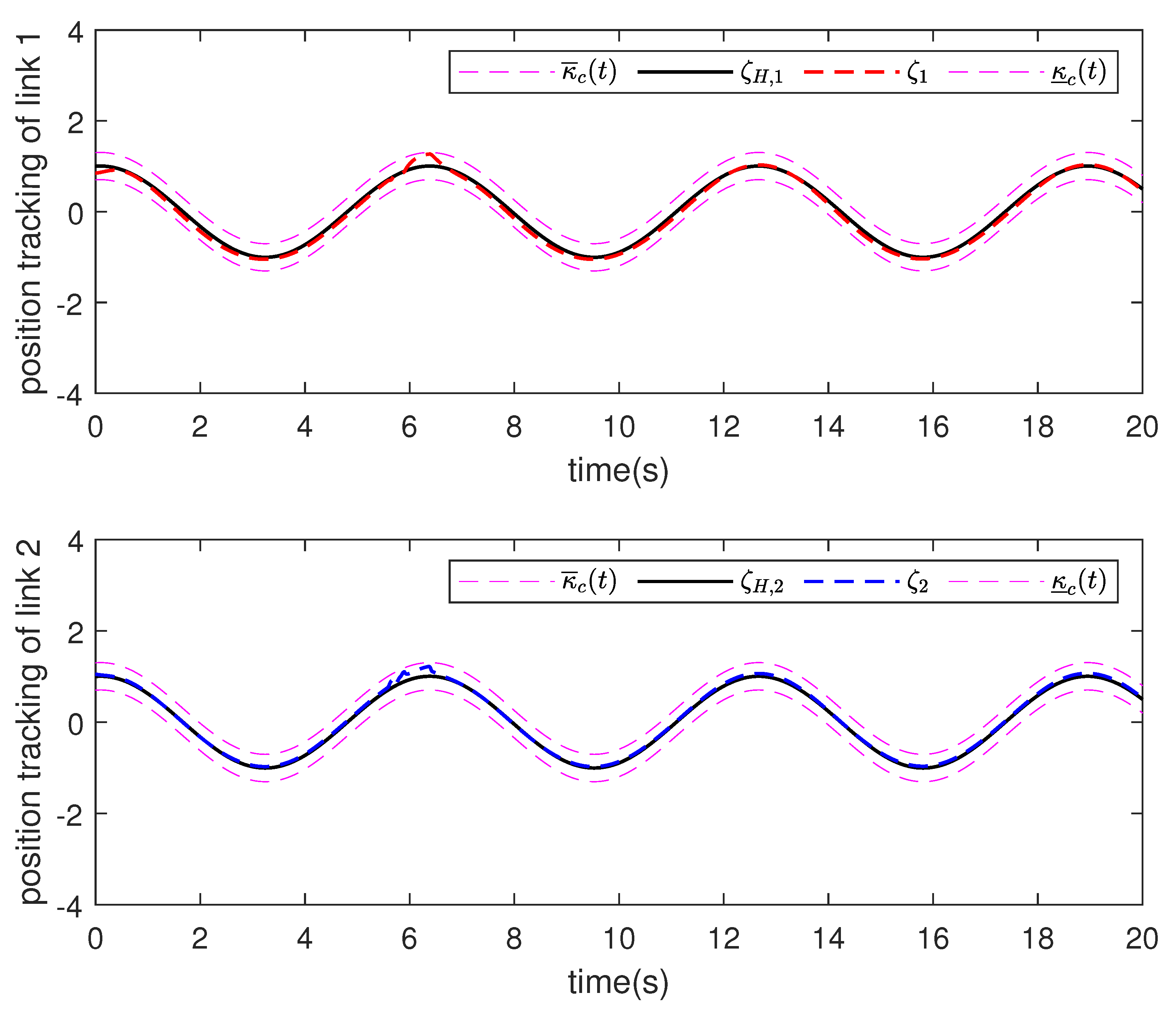
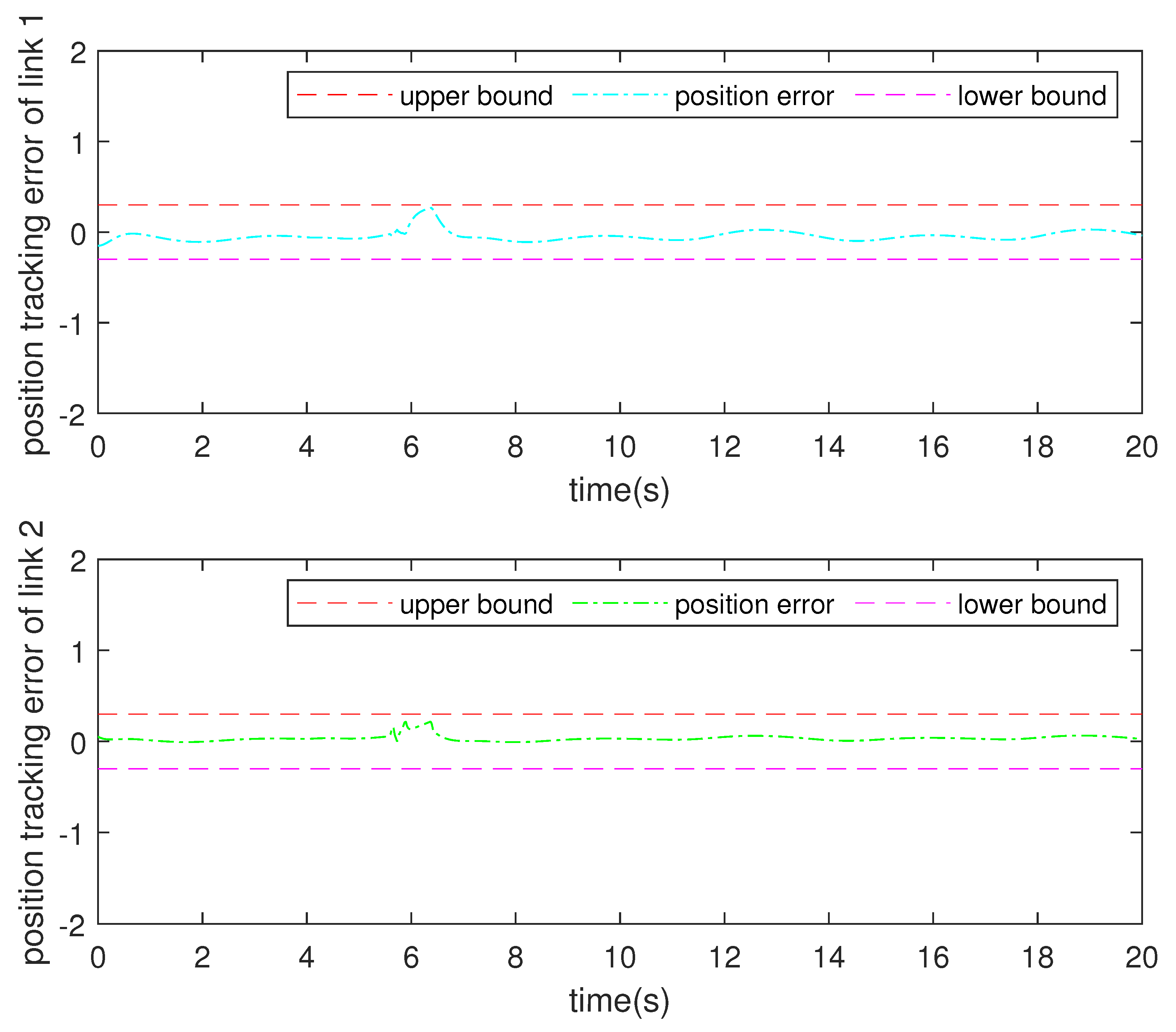
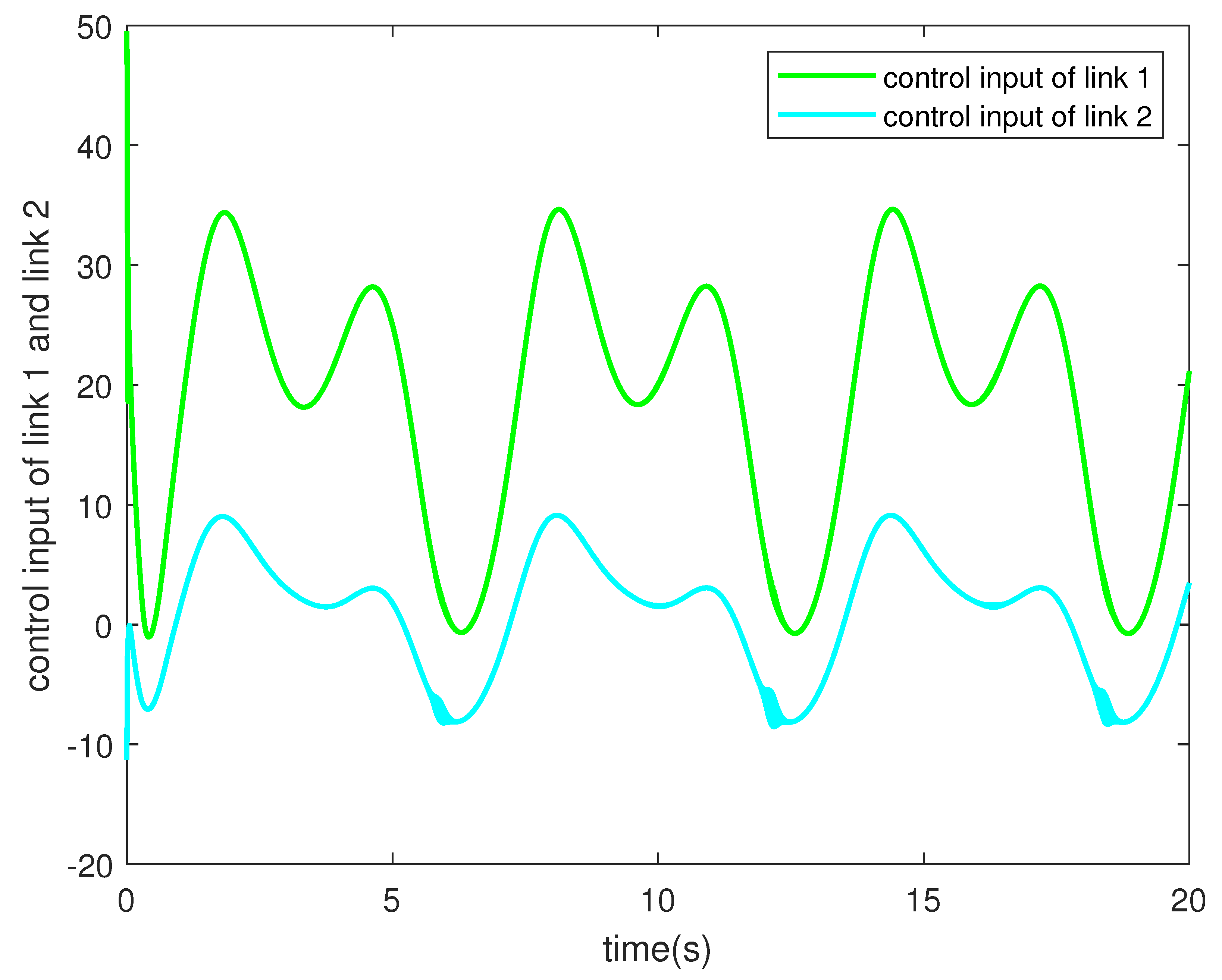
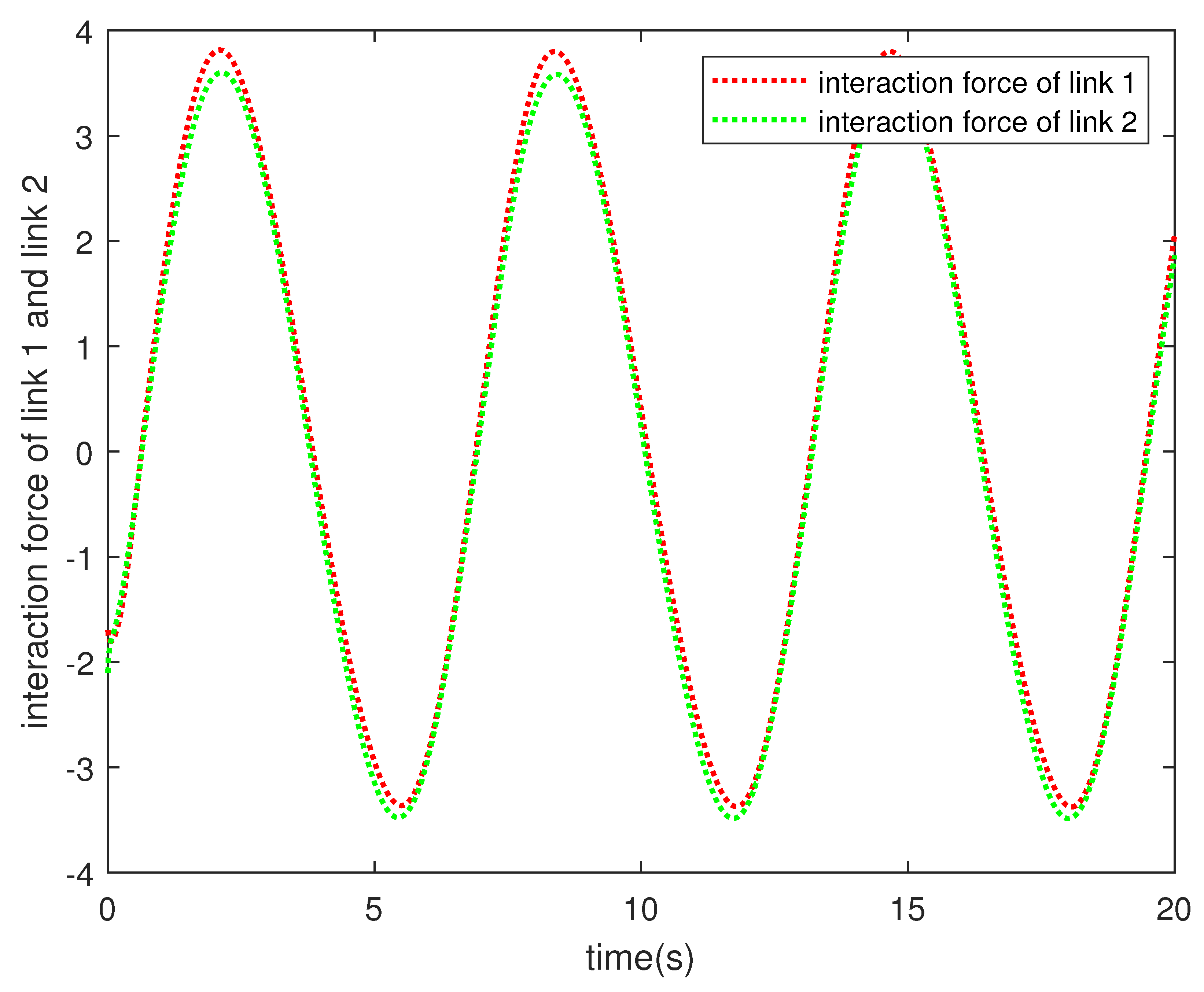
For our proposed adaptive neural network control law, we chose 16 RBFNN nodes, the centers for Δ i ( Z ) were [ 1 , 1 ] 4 , and the RBFNN weights were initialized from zero. The gain matrix was set as K = d i a g [ 20 , 20 ] . The output constraints were designed as κ ̲ c = κ ¯ c = 0.3 . The position tracking performance is shown in Figure 3 and Figure 4. From Figure 3 and Figure 4, it can be seen that the output of the exoskeleton can follow the expected trajectory, and the tracking error can converge to a small area near zero. The RMSEs (Root Mean Square Errors) of the position tracking errors of joint 1 and joint 2 are 0.0597 (rad) and 0.0373 (rad), respectively. Moreover, the output constraint rule is not violated. Figure 5 shows the velocity tracking performance of the controller. The RMSEs of the velocity tracking errors of joint 1 and joint 2 are 0.0792 (rad/s) and 0.0353 (rad/s), respectively. The robustness of the controller against external disturbances is tested and depicted in Figure 6 and Figure 7. These figures demonstrate that the proposed controller exhibits strong robustness to external disturbances. Although some fluctuations appear when the disturbances occur, the actual tracking curves consistently remain within the constraint boundaries. Figure 8 and Figure 9 indicate that the output torque and human–exoskeleton interaction torque of the controller are regularly bounded.

4.2. Comprehensive Simulation

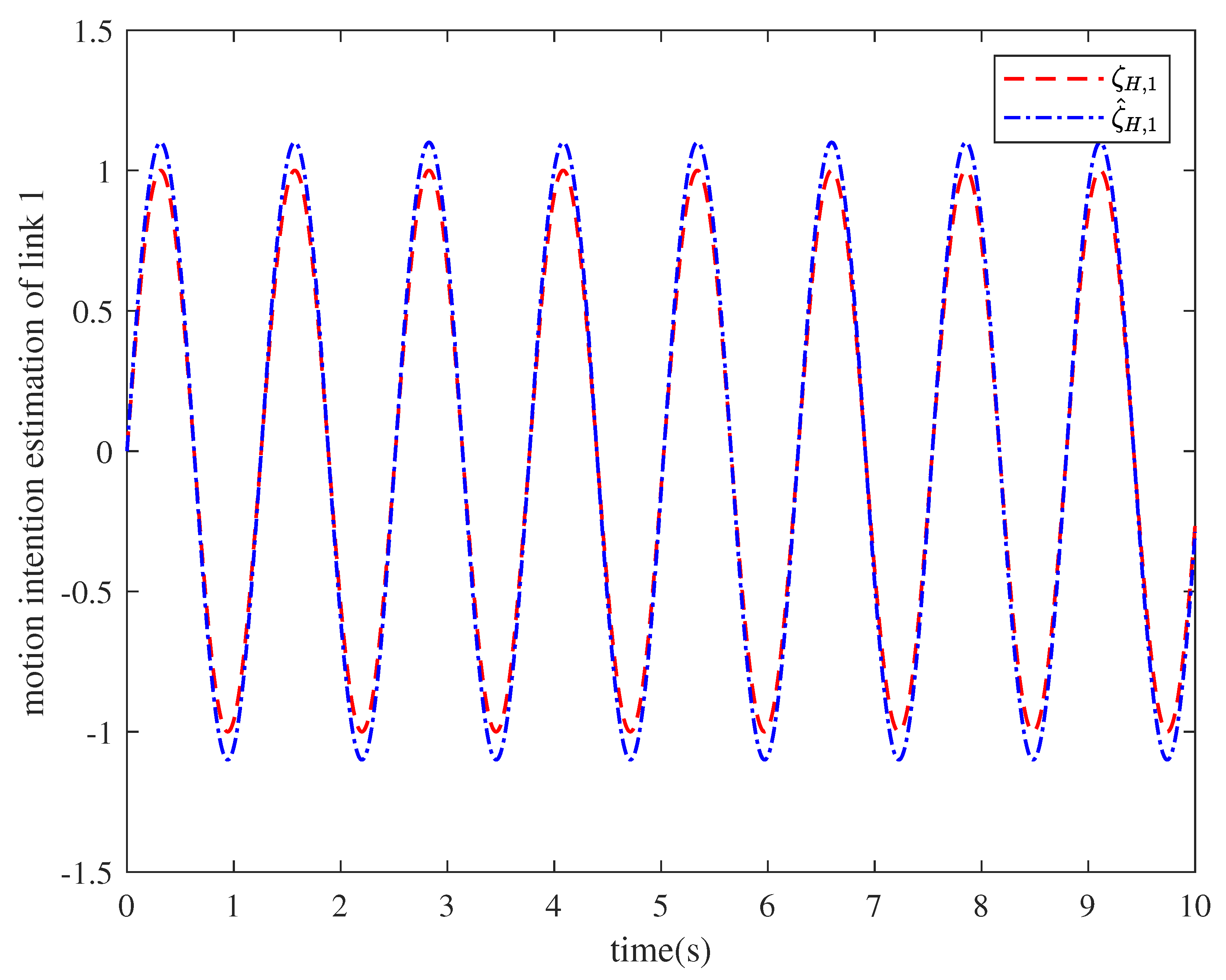
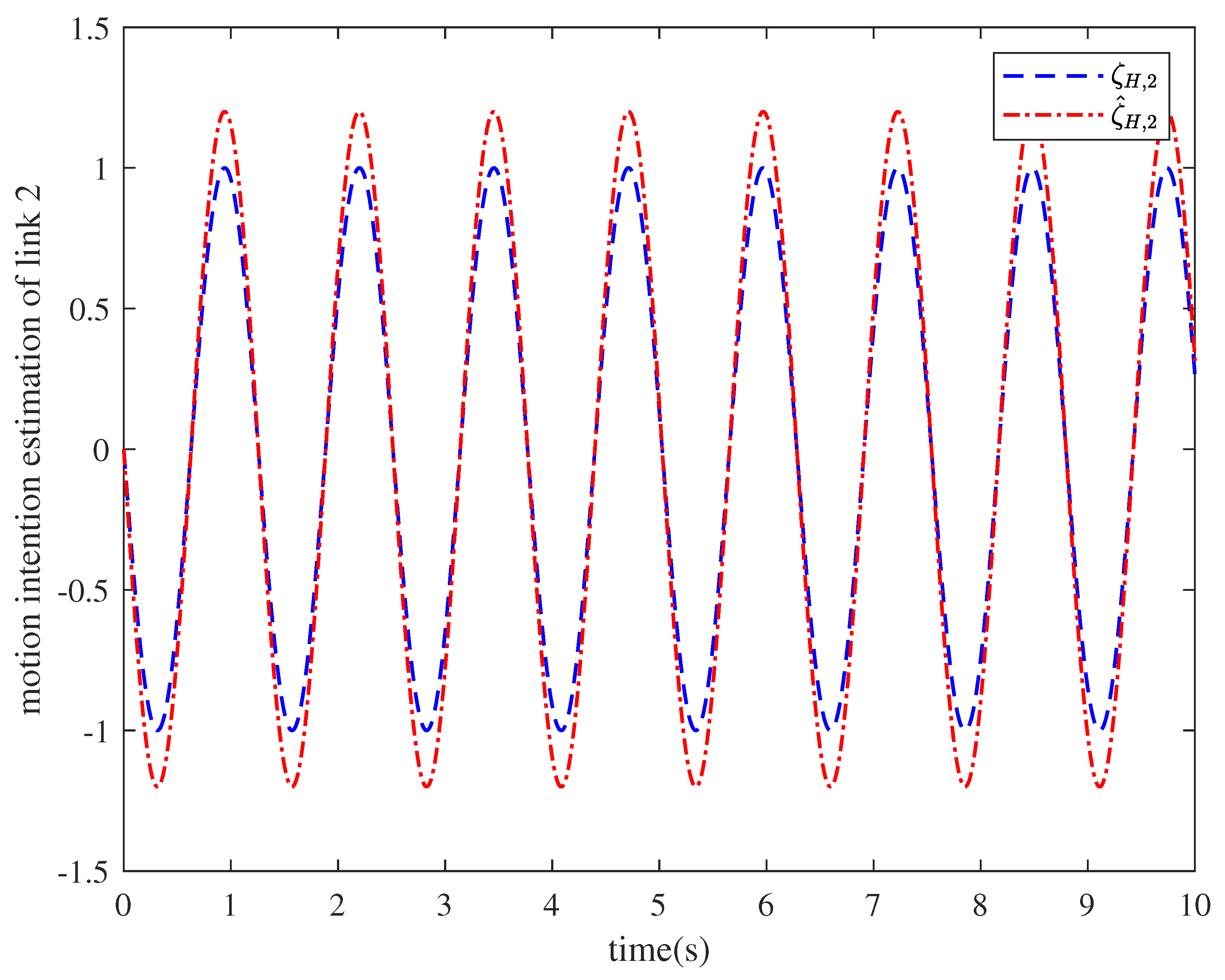
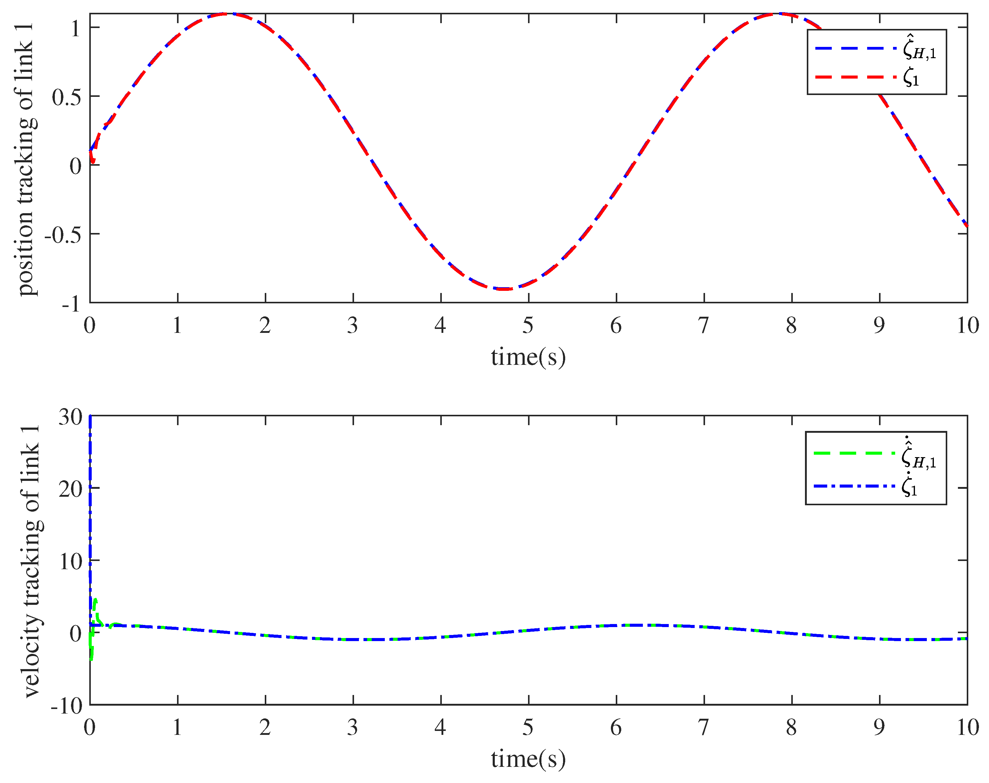
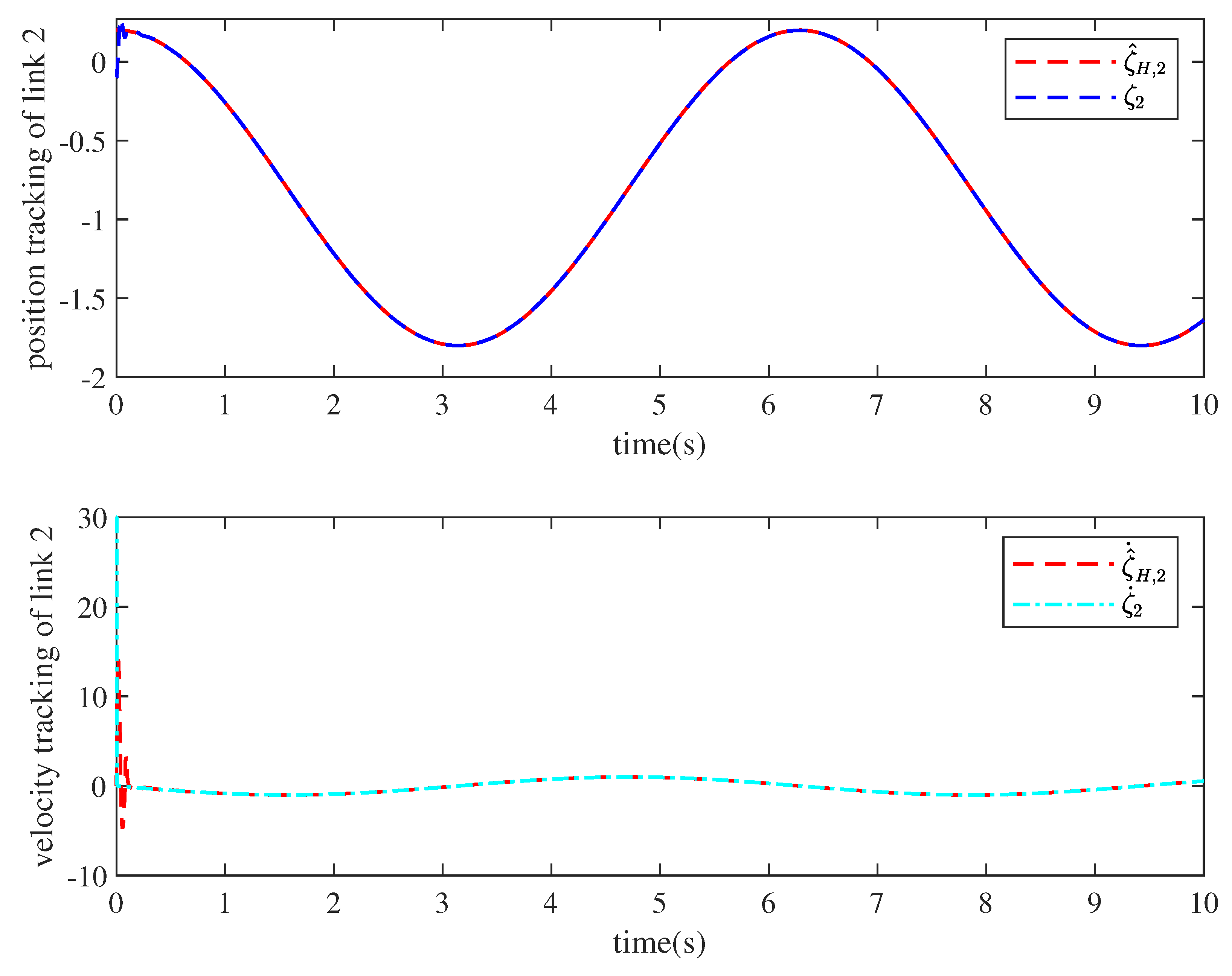
The human motion intention estimation scheme for ζ ^ H , i is given in (10) with the weight of the RBFNN adjusted using (15). The center nodes and initial value of the RBFNN are the same as in Section 4.1. Figure 10 and Figure 11 show the performance of the human motion estimation. It can be seen that the motion estimation is successfully achieved, which indicates feasibility in clinical application.
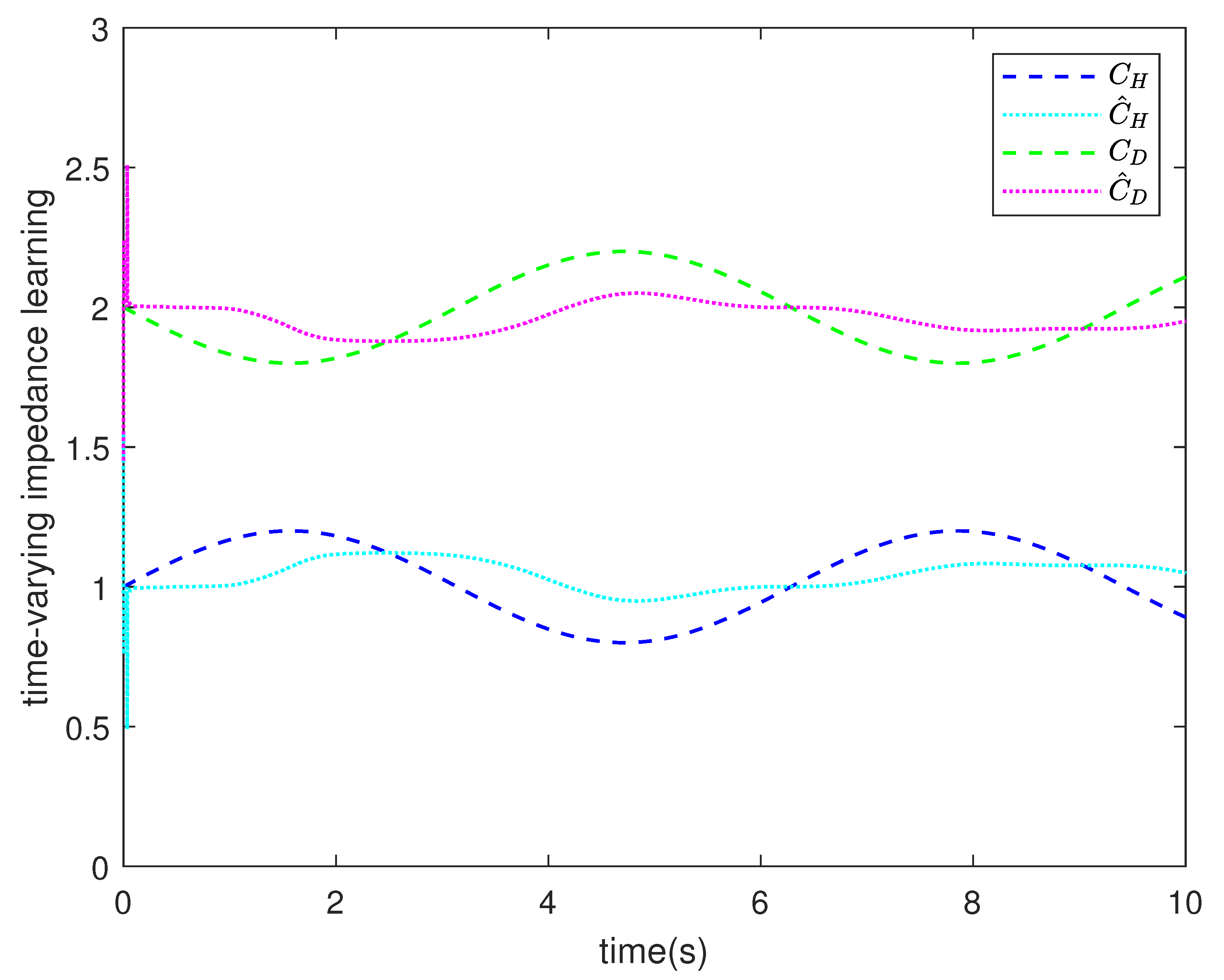
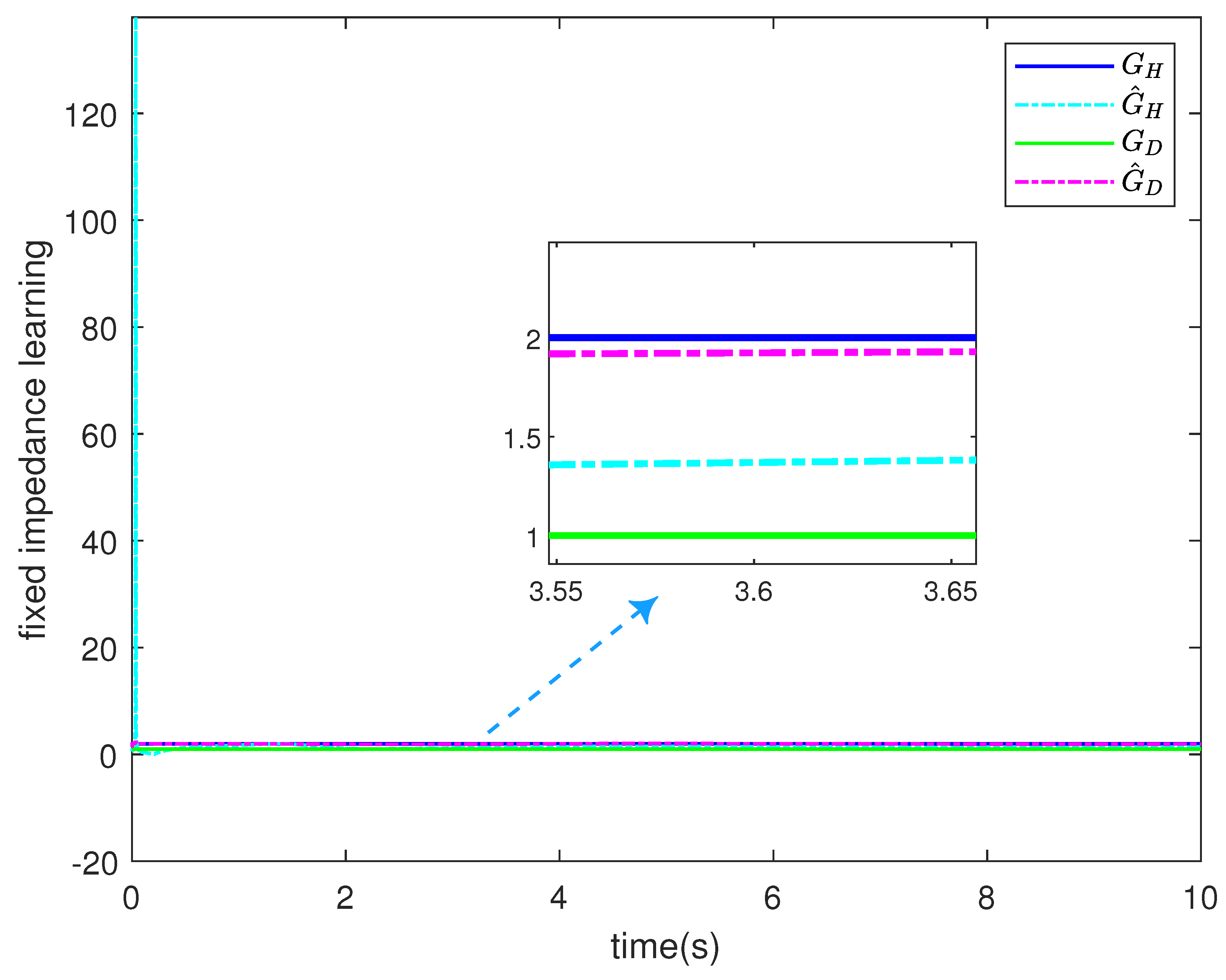
To illustrate the learning performance of human impedance parameters, we consider two scenarios: unknown fixed impedance and time-varying impedance. Set parameter C ¯ = d i a g [ 3 , 3 ] and G ¯ = d i a g [ 3 , 3 ] . The fixed impedance parameter is selected as G H = d i a g [ 2 , 2 ] and the time-varying impedance parameter is selected as C H = d i a g [ 1 + 0.2 sin t , 1 + 0.2 sin t ] . According to Figure 12 and Figure 13, it is found that the fixed stiffness parameters and time-varying damping parameters of the human body can be obtained, and the corresponding expected exoskeleton impedance parameters can be obtained. Similarly, this method can effectively obtain the fixed damping parameters and time-varying stiffness parameters of human body. In Figure 14 and Figure 15, it can be seen that the controller of the lower limb rehabilitation exoskeleton system still has good control performance after integrating human motion intention estimation and impedance learning, which proves the rationality of the proposed scheme.

5. Conclusions

In this paper, an adaptive neural network impedance control scheme based on human motion intention estimation is proposed to solve the human–robot interaction problem of lower limb exoskeletons in the later stage of rehabilitation. In order to improve the flexibility of rehabilitation training and meet personalized rehabilitation needs, the motion intention estimation and impedance learning methods were proposed. An RBF neural network was used to estimate the motion intention of patients, and the least square method was used to learn the impedance parameters. In the control system, the RBF neural network is used to compensate for the uncertainty of exoskeleton dynamics, and the BLF is selected to ensure that the output constraint rules are not violated. The stability of the closed-loop system is proved by the Lyapunov method. The simulation results show that both the parameter learning scheme and the control scheme designed in this paper can achieve the desired goal and effectively improve the effects of lower limb rehabilitation for patients. The proposed control scheme requires prior knowledge of the system model, which creates restrictions in terms of real-time implementation. Further work involves investigating a model-free controller through experimental validation.

Author Contributions

Conceptualization, J.M. and Y.Y.; methodology, J.M. and H.C.; validation, J.M. and H.C.; investigation, J.M. and X.L.; writing—original draft, J.M., H.C. and X.L.; writing—review and editing, H.C. and Y.Y.; supervision, Y.Y. and D.H.; project administration, Y.Y. and D.H. All authors have read and agreed to the published version of the manuscript.

Funding

This work was supported in part by the National Natural Science Foundation of China under Grant 62003278 and in part by the Natural Science Foundation of Sichuan Province under Grant 2023NSFSC1431.

Institutional Review Board Statement

Not applicable.

Informed Consent Statement

Not applicable.

Data Availability Statement

Data is contained within the article.

Conflicts of Interest

The authors declare no conflicts of interest.

References

  1. Huo, Y.X.; Li, X.; Zhang, X.; Li, X.; Sun, D. Adaptive Intention-Driven Variable Impedance Control for Wearable Robots with Compliant Actuators. IEEE Trans. Control Syst. Technol. 2023, 31, 1308–1323. [Google Scholar] [CrossRef]
  2. Zhang, P.F.; Gao, X.S.; Miao, M.D.; Zhao, P. Design and Control of a Lower Limb Rehabilitation Robot Based on Human Motion Intention Recognition with Multi-Source Sensor Information. Machines 2023, 10, 1125. [Google Scholar] [CrossRef]
  3. Du, G.M.; Ding, Z.; Guo, H.; Song, M.C.; Jiang, F. Estimation of Lower Limb Joint Angles Using sEMG Signals and RGB-D Camera. Bioengineering 2024, 11, 1026. [Google Scholar] [CrossRef] [PubMed]
  4. Plaza, A.; Hernandez, M.; Puyuelo, G.; Garces, E.; Garcia, E. Lower-Limb Medical and Rehabilitation Exoskeletons: A Review of the Current Designs. IEEE Rev. Biomed. Eng. 2023, 16, 278–291. [Google Scholar] [CrossRef]
  5. Jenhani, S.; Gritli, H.; Narayan, J. Robust Position Control of a Knee-Joint Rehabilitation Exoskeleton Using a Linear Matrix Inequalities-Based Design Approach. Appl. Sci. 2025, 15, 404. [Google Scholar] [CrossRef]
  6. Zhou, J.; Peng, H.F.; Sue, S.; Song, S. Spatiotemporal Compliance Control for a Wearable Lower Limb Rehabilitation Robot. IEEE Trans. Biomed. Eng. 2023, 70, 1858–1868. [Google Scholar] [CrossRef] [PubMed]
  7. Li, J.; Lan, C.R.; Liang, P.; Zhong, M.Y.; Shi, X.L.; Lv, Y.L. Research on Interactive Force Acquisition and Active–Passive Mode Determination of Rehabilitation Robot. Measurement 2023, 220, 113340. [Google Scholar] [CrossRef]
  8. Matinfar, M.; Hashtrudi-Zaad, K. Optimization-Based Robot Compliance Control: Geometric and Linear Quadratic Approaches. Int. J. Robot. Res. 2005, 24, 645–656. [Google Scholar] [CrossRef]
  9. Lu, W.-S.; Meng, Q.-H. Impedance Control with Adaptation for Robotic Manipulations. IEEE Trans. Robot. Autom. 1991, 7, 408–415. [Google Scholar] [CrossRef]
  10. Wang, Y.Y.; Yan, F.; Chen, J.W.; Ju, F.; Chen, B. A New Adaptive Time-Delay Control Scheme for Cable-Driven Manipulators. IEEE Trans. Ind. Inform. 2019, 15, 3469–3481. [Google Scholar] [CrossRef]
  11. Hogan, N. Impedance Control: An Approach to Manipulation. Part I: Theory; Part II: Implementation; Part III: Applications. J. Dyn. Syst. Meas. Control 1985, 107, 8–16. [Google Scholar] [CrossRef]
  12. Sun, Y.H.; Hu, J.P.; Huang, R. Negative-Stiffness Structure Vibration-Isolation Design and Impedance Control for a Lower Limb Exoskeleton Robot. Actuators 2023, 12, 147. [Google Scholar] [CrossRef]
  13. Liu, L.; Illian, M.; Leonhardt, S.; Misgeld, B.J.E. Iterative Learning Control for Cascaded Impedance-Controlled Compliant Exoskeleton with Adaptive Reaction to Spasticity. IEEE Trans. Instrum. Meas. 2023, 72, 4008211. [Google Scholar] [CrossRef]
  14. Zhang, Q.; Si, J.; Tu, X.K.; Li, M.H.; Lewek, M.D.; Huang, H. Toward Task-Independent Optimal Adaptive Control of a Hip Exoskeleton for Locomotion Assistance in Neurorehabilitation. IEEE Trans. Syst. Man Cybern.-Syst. 2024, 54, 7592–7604. [Google Scholar] [CrossRef]
  15. Yang, Y.; Huang, D.Q.; Jin, C.W.; Liu, X.; Li, Y.A. Neural Learning Impedance Control of Lower Limb Rehabilitation Exoskeleton with Flexible Joints in the Presence of Input Constraints. Int. J. Robust Nonlinear Control 2022, 33, 4191–4209. [Google Scholar] [CrossRef]
  16. Lee, H.Y.W.; Lee, J.N.; Keppler, M.; Oh, S. Robust Elastic Structure Preserving Control for High Impedance Rendering of Series Elastic Actuator. IEEE Robot. Autom. Lett. 2024, 9, 3601–3608. [Google Scholar] [CrossRef]
  17. Li, L.S.; Wang, F.; Tang, H.; Liang, Y.B. Variable-Parameter Impedance Control of Manipulator Based on RBFNN and Gradient Descent. Sensors 2024, 25, 49. [Google Scholar] [CrossRef]
  18. Sun, Y.H.; Peng, Z.A.; Hu, J.P.; Ghosh, B.K. Event-Triggered Critic Learning Impedance Control of Lower Limb Exoskeleton Robots in Interactive Environments. Neurocomputing 2024, 564, 126963. [Google Scholar] [CrossRef]
  19. Li, J.W.; Lu, L.; Zhao, L.D.; Wang, C.; Li, J.H. An Integrated Approach for Robotic Sit-to-Stand Assistance: Control Framework Design and Human Intention Recognition. Control Eng. Pract. 2021, 107, 104680. [Google Scholar] [CrossRef]
  20. Tang, C.Y.; Xu, Z.Y.; Occhipinti, E.; Yi, W.T.; Xu, M.Z.; Kumar, S.; Virk, G.S.; Gao, S.; Occhipinti, L.G. From Brain to Movement: Wearables-Based Motion Intention Prediction Across the Human Nervous System. Nano Energy 2023, 115, 108712. [Google Scholar] [CrossRef]
  21. Pan, Y.; Chen, C.J.; Zhao, Z.X.; Hu, T.L.; Zhang, J.H. Robot Teaching System Based on Hand-Robot Contact State Detection and Motion Intention Recognition. Robot. Comput.-Integr. Manuf. 2023, 81, 102492. [Google Scholar] [CrossRef]
  22. Kueper, N.; Kim, S.K.; Kirchner, E.A. Avoidance of Specific Calibration Sessions in Motor Intention Recognition for Exoskeleton-Supported Rehabilitation Through Transfer Learning on EEG Data. Sci. Rep. 2024, 14, 16690. [Google Scholar] [CrossRef] [PubMed]
  23. Wang, D.J.; Gu, X.P.; Yu, H.L. A Comparison of Four Neural Networks Algorithms on Locomotion Intention Recognition of Lower Limb Exoskeleton Based on Multi-Source Information. J. Bionic Eng. 2024, 21, 224–235. [Google Scholar] [CrossRef]
  24. Sharifi, M.; Azimi, V.; Mushahwar, V.K.; Tavakoil, M. mpedance Learning-Based Adaptive Control for Human–Robot Interaction. IEEE Trans. Control Syst. Technol. 2022, 30, 1345–1358. [Google Scholar] [CrossRef]
  25. Kim, B.; Park, J.; Park, S.; Kang, S. Impedance Learning for Robotic Contact Tasks Using Natural Actor-Critic Algorithm. IEEE Trans. Syst. Man Cybern. Part B-Cybern. 2010, 40, 433–443. [Google Scholar]
  26. Tsuji, T.; Ito, K.; Morasso, P.G. Neural Network Learning of Robot Arm Impedance in Operational Space. IEEE Trans. Syst. Man Cybern. Part B-Cybern. 1996, 26, 290–298. [Google Scholar] [CrossRef]
  27. Chang, P.H.; Park, K.; Kang, S.H.; Krebs, H.I.; Hogan, N. Stochastic Estimation of Human Arm Impedance Using Robots with Nonlinear Frictions: An Experimental Validation. IEEE-ASME Trans. Mechatron. 2013, 18, 775–786. [Google Scholar] [CrossRef]
  28. Zhang, X.Q.; Zhang, J.X.; Xiong, G.L.; Gao, Y.F.; Feng, Y. Research on Adaptive Fuzzy Impedance Control of Human-Massage Robot Interaction Based on Kelvin-Voigt Modeling. IEEE Access 2024, 12, 89562–89572. [Google Scholar] [CrossRef]
  29. Yang, Y.; Li, Y.A.; Liu, X.; Huang, D.Q. Adaptive Neural Network Control for a Hydraulic Knee Exoskeleton with Valve Deadband and Output Constraint Based on Nonlinear Disturbance Observer. Neurocomputing 2022, 473, 14–23. [Google Scholar] [CrossRef]
  30. Xu, M.M.; Wu, Y.Q. Event-Based Fuzzy Stabilization Controller for Uncertain Nonholonomic Systems with Output Constraints: Application to Mobile Robots. IEEE Trans. Autom. Sci. Eng. 2024. [Google Scholar] [CrossRef]
  31. Yang, S.Y.; Pei, J.F.; Liu, Y.Y.; Chen, Y.H. Robust Tracking Control Design with a Novel Leakage-Type Adaptive Mechanism for an Uncertain Lower Limb Exoskeleton Robot. J. Vib. Control 2023, 29, 2681–2695. [Google Scholar] [CrossRef]
  32. Sun, J.J.; Wang, J.; Yang, P.; Guo, S.J. Fractional-Order Prescribed Performance Sliding-Mode Control with Time-Delay Estimation for Wearable Exoskeletons. IEEE Trans. Ind. Inform. 2023, 19, 8274–8284. [Google Scholar] [CrossRef]
  33. Tee, K.P.; Ren, B.B.; Ge, S.S. Control of Nonlinear Systems with Time-Varying Output Constraints. Automatica 2011, 47, 2511–2516. [Google Scholar] [CrossRef]
  34. Li, Z.J.; Yuan, W.; Chen, Y.; Ke, F.; Chu, X.L.; Chen, C.L.P. Neural-Dynamic Optimization-Based Model Predictive Control for Tracking and Formation of Nonholonomic Multirobot Systems. IEEE Trans. Neural Netw. Learn. Syst. 2018, 29, 6113–6122. [Google Scholar] [CrossRef] [PubMed]
  35. Le, Q.D.; Yang, E.F. Adaptive Fault-Tolerant Tracking Control for Multi-Joint Robot Manipulators via Neural Network-Based Synchronization. Sensors 2024, 24, 6837. [Google Scholar] [CrossRef] [PubMed]
  36. Yin, M.; Shang, D.Y.; Cao, W.J.; Ma, Y.; Li, J.K.; Tian, D.K.; Wu, X.Y. Rotation Angle Control Strategy for the Hip Joint of an Exoskeleton Robot Assisted by Paraplegic Patients Considering Time-Varying Inertia. IEEE Trans. Autom. Sci. Eng. 2024. [Google Scholar] [CrossRef]
  37. Yang, G.C.; Yao, J.Y. Multilayer Neurocontrol of High-Order Uncertain Nonlinear Systems with Active Disturbance Rejection. Int. J. Robust Nonlinear Control 2024, 34, 2972–2987. [Google Scholar] [CrossRef]
  38. Wang, H.T.; Liu, Q.S.; Xu, C.T. Predefined-Time Distributed Optimization and Anti-Disturbance Control for Nonlinear Multi-Agent System with Neural Network Estimator: A Hierarchical Framework. Neural Netw. 2024, 175, 106270. [Google Scholar] [CrossRef]
  39. Zhang, N.; Xia, J.W.; Park, J.H.; Zhang, J.; Shen, H. Improved Disturbance Observer-Based Fixed-Time Adaptive Neural Network Consensus Tracking for Nonlinear Multi-Agent System. Neural Netw. 2023, 162, 490–501. [Google Scholar] [CrossRef] [PubMed]
  40. Espinosa-Espejel, K.I.; Rosales-Luengas, Y.; Salazar, S.; López-Gutiérrez, R.; Lozano, R. Active Disturbance Rejection Control via Neural Networks for a Lower-Limb Exoskeleton. Sensors 2024, 24, 6546. [Google Scholar] [CrossRef] [PubMed]
  41. Yang, Y.; Dong, X.C.; Huang, D.Q. Enhanced Neural Network Control of Lower Limb Rehabilitation Exoskeleton by Add-On Repetitive Learning. Neurocomputing 2019, 323, 256–264. [Google Scholar] [CrossRef]
  42. Khatib, O.; Warren, J.; Sapio, V.D.; Sentis, L. Human-Like Motion from Physiologically-Based Potential Energies. Adv. Robot Kinemat. 2004, 149–163. Available online: https://link.springer.com/chapter/10.1007/978-1-4020-2249-4_16 (accessed on 2 December 2024).
  43. Lalitharatne, T.; Teramoto, K.; Hayashi, Y.; Kiguchi, K. Evaluation of Perception-Assist with an Upper-Limb Powerassist Exoskeleton Using EMG and EEG Signals. In Proceedings of the 11th IEEE International Conference on Networking, Sensing and Control, Sensing and Control, ICNSC 2014, Marseille, France, 25–27 October 2014; pp. 524–529. [Google Scholar]
  44. Ge, S.S.; Lee, T.H.; Harris, C.J. Adaptive Neural Network Control of Robotic Manipulators; World Scientific: Singapore, 1998. [Google Scholar]
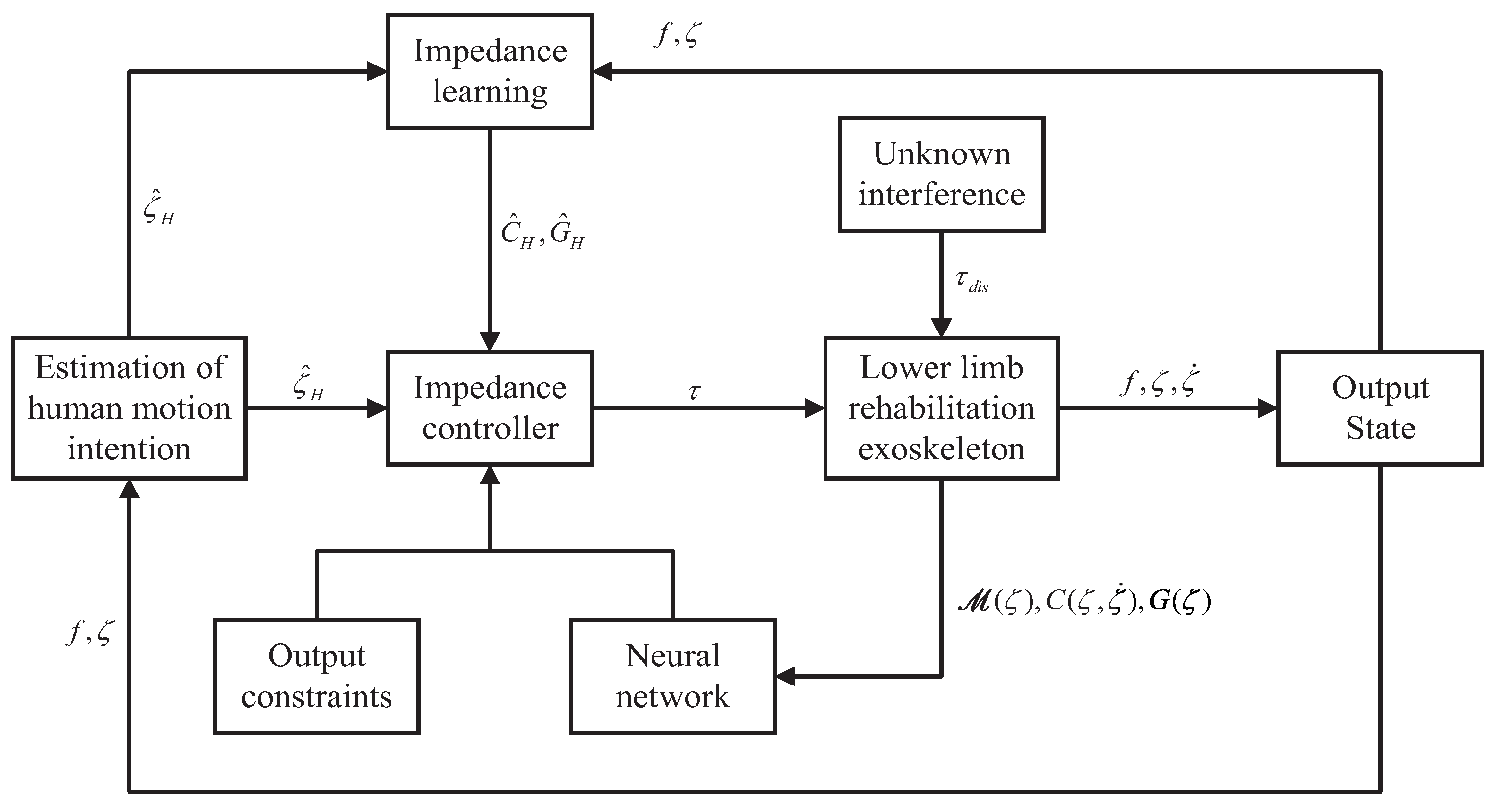
Figure 1. Control structure.
Applsci 15 01271 g001
Figure 2. Exoskeleton output constraint diagram.
Applsci 15 01271 g002
Figure 3. Position tracking of exoskeleton.
Applsci 15 01271 g003
Figure 4. The tracking errors of the exoskeleton.
Applsci 15 01271 g004
Figure 5. Velocity tracking of exoskeleton.
Applsci 15 01271 g005
Figure 6. Position tracking of exoskeleton with disturbance.
Applsci 15 01271 g006
Figure 7. Position tracking error with disturbance.
Applsci 15 01271 g007
Figure 8. Controller output torque.
Applsci 15 01271 g008
Figure 9. Human–exoskeleton interaction torque.
Applsci 15 01271 g009
Figure 10. Motion intention estimation of joint 1.
Applsci 15 01271 g010
Figure 11. Motion intention estimation of joint 2.
Applsci 15 01271 g011
Figure 12. Time-varying impedance learning.
Applsci 15 01271 g012
Figure 13. Fixed impedance learning.
Applsci 15 01271 g013
Figure 14. Position and velocity tracking of joint 1.
Applsci 15 01271 g014
Figure 15. Position and velocity tracking of joint 2.
Applsci 15 01271 g015
Table 1. Exoskeleton system parameters.
ParameterDescriptionValue
m 1 Mass of link 1 10 kg
m 2 Mass of link 2 5 kg
l 1 Length of link 1 0.5 m
l 2 Length of link 2 0.4 m
I 1 Inertia of link 1 1.2 m 2 · kg
I 2 Inertia of link 2 1 m 2 · kg
Disclaimer/Publisher’s Note: The statements, opinions and data contained in all publications are solely those of the individual author(s) and contributor(s) and not of MDPI and/or the editor(s). MDPI and/or the editor(s) disclaim responsibility for any injury to people or property resulting from any ideas, methods, instructions or products referred to in the content.