Article

Cost-Effective FEM Simulation Through Solid Bodies of the Thermal Behavior of Lattice Structures Printed via PBF-LB

1
Department of Mechanical Engineering, University of the Basque Country (UPV/EHU), Plaza Torres Quevedo 1, 48013 Bilbao, Spain
2
Faculty of Engineering, Mondragon Unibertsitatea, Loramendi 4, 20500 Arrasate, Spain
3
Ceit-BRTA, Manuel Lardizábal 15, 200218 Donostia-San Sebastián, Spain
4
Tecnun. Escuela de Ingeniería, Universidad de Navarra, Manuel Lardizábal 13, 200218 Donostia-San Sebastián, Spain
*
Author to whom correspondence should be addressed.
Appl. Sci. 2025, 15(3), 1372; https://doi.org/10.3390/app15031372
Submission received: 18 December 2024 / Revised: 16 January 2025 / Accepted: 24 January 2025 / Published: 28 January 2025
(This article belongs to the Special Issue Additive Manufacturing Technologies in Alloys Processing)

Abstract

:

Featured Application

The developed approach will allow the thermal simulation of lattice structures as solid bodies. This is especially interesting when designing lattice structures to be printed via PBF-LB, as it will allow the design of thermally optimized components at a low computational cost.

Abstract

Laser additive manufacturing, and specifically laser powder bed fusion (PBF-LB) enables the production of complex geometries with optimized features that provide unique features to components. One of the main advantages of PBF-LB is its capability to produce reticular or lattice-type geometries that considerably reduce the weight of the components. Lattice geometries are widely used to optimize components mechanically, but, to date, their thermal capabilities have not been studied in depth. Therefore, in the present work, the thermal behavior of lattice structures is analyzed experimentally and correlated with finite element models. Nevertheless, the simulation of lattice structures is highly costly from a computational point of view. In order to solve this issue, the present work develops a novel methodology based on fictitious solid materials that behave thermally as the lattice structure. The results show strong resemblance between the thermal behavior of fictitious solid and lattice structures, with temperature errors below 2%, and it reduces the computational cost required for their simulation by up to 90%. Moreover, the obtained results open the door to the design of anisotropic components based on lattice structures, as well as increasing the design capabilities for this type of structure.

1. Introduction

Nickel-based superalloys, such as Inconel 718, are widely employed in the aircraft industry thanks to their outstanding mechanical properties at high temperatures [1]. However, they present a relatively high density, which raises the total weight of the components. Hence, the use of lattice-type structures has been employed recently to reduce the relative density of these components [2]. Lattice structures are defined as regularly repeated patterns that propagate in all directions and are based on unit cells. This nature, combined with the hollow voids between the struts, promotes a considerable reduction in the amount of material per unit volume compared to the equivalent solid component [3]. Hence, they enable a holistic mass reduction in systems where mass and volume savings are the main design drivers, i.e., aerospace or automotive systems.
The development of additive manufacturing (AM) technologies, and mainly PBF-LB, has opened up a range of new opportunities as it enables the manufacturing of complex geometries at no cost increase [4], as well as control over the anisotropy of the deposited material and an increase in design freedom [5]. For instance, Flores et al. concluded that the use of lattice structures when manufacturing components via PBF-LB could reduce the manufacturing cost by 53.7% and the manufacturing time by 54.3%, and it results in an overall reduction in weight of 52.5% [6]. Moreover, the use of lattice structures reduces the amount of material deposited in the process and hence optimizes the manufacturing time and the cost of production [7]. Consequently, a great deal of research effort has recently been focused on this field. For example, Leary et at. studied the viability of manufacturing lattice structures and they concluded that topology selection enables a coarse mechanism for the tuning of the structural strength and stiffness [8].
Similarly, researchers have explored the potential applications of lattice structures in thermal systems. Sajjad et al. reviewed the heat transfer applications of these structures, where heat exchangers, heat sinks, and heat pipes are highlighted [9]. Piacquadio et al. investigated experimentally the thermal performance of composite samples with different unit cell topologies [10]. They analyzed different cell units under different gravity orientations, and the body-centered cubic (bcc) sample showed the lowest effective conductivity in the Z direction, as no struts were manufactured in this direction, and its thermal conductivity was the same in the three analyzed directions (X, Y, and Z). However, this is the result of employing a non-distorted structure, and any elongation of the lattice structure would produce asymmetric behavior.
Topology optimization strategies are possible also to improve the heat conduction capabilities of lattice structures. Gao et al. included design-dependent loads in the design optimization tool based on finite elements [11], but it was employed only in 2D cases, and the applicability of the results was focused on electronic components. Similarly, Iga et al. proposed a topology optimization technique to maximize the thermal diffusivity of thermal conductors [12], but dendritic-shaped structures were generated to maximize the thermal diffusivity. Yamada et al. presented a strategy based on level set modeling to maximize the thermal diffusivity in heat transfer issues with design-dependent boundary conditions [13]. The obtained algorithm was based on finite elements and enables one to design thermally optimized 2D lattice structures, but the thermal behavior of full lattice components was not studied; this would imply an extremely high computational cost.
The most commonly employed simulation approach is the numerical one, because it offers high flexibility while providing accurate results. Nevertheless, the numerical simulation of whole lattice structures is a complex task to achieve, as the thin nature of the struts necessitates the use of small-sized elements that increase exponentially the computational cost of the calculations. Zhou et al. performed, in their research, a thermal evaluation of lattice structures, and, for the bcc configuration, over three million elements were required for a 6 × 24 × 6 mm3 lattice domain [14]. Therefore, to reduce the computational cost associated with the finite element model, strategies such as space partitioning and dynamic mesh adaption have been employed [15]. Hence, after this review of the state of the art, it is concluded that there is room for improvement in the thermal characterization of lattice structures.
Consequently, in the present work, the PBF-LB technology is employed for the manufacturing of lattice samples to be experimentally analyzed, and their behavior is simulated with finite element modeling (FEM). The novelty of the present research work lies in the fact that the behavior of the lattice structures is not only analyzed by discretizing the geometry of the lattice, but, instead, an equivalent fictitious solid material is designed that behaves as the original lattice structure’s but at a reduced computational cost. In order to achieve this simplification, the methodology to be followed has been developed and validated.

2. Materials and Methods

This section describes the methodology used. First, the material characterization is indicated, which enables the simulation of the properties of real manufactured components. Afterwards, the experimental procedure for the thermal performance analysis of the lattice structure is explained.

2.1. Procedure for the Characterization of Inconel 718’s Thermal Properties

The thermal properties of Inconel 718 are experimentally measured. The density of the material, ρ , is measured using a Linseis L75 Platinum dilatometer machine (Linseis Messgeräte GmbH, Selb, Germany) at a heating rate of 10 °C/s, the specific heat (cp) in an STA 449 F3 Jupiter DSC machine (NETZSCH-Gerätebau GmbH, Selb, Germany), and the thermal diffusivity, α , in the LFA 457 MicroFlash laser flash equipment (NETZSCH-Gerätebau GmbH, Selb, Germany). The thermal properties are measured in the range of room temperature (20 °C) and 1000 °C, which covers the temperature range in which Inconel 718 is typically employed. Table 1 summarizes the sample dimensions and employed equipment. The thermal conductivity value ( k ) required for the FEM simulations is obtained through Equation (1).
k T = ρ T · c p T · α ( T )

2.2. Methodology

The approximation of a lattice-shaped geometry into a solid block is performed in three stages. First of all, the designed lattice geometries are printed in a PBF-LB machine and their thermal behavior is experimentally characterized. In the second step, the behavior of the lattice structures is simulated through FEM analysis, which ensures that the digital model behaves equally to the real component. Finally, in the third step, the behavior of the digital lattice is approximated through a solid block. For this purpose, the thermomechanical properties of the material are adapted and a fictitious solid material that behaves equally to the lattice structure is defined.

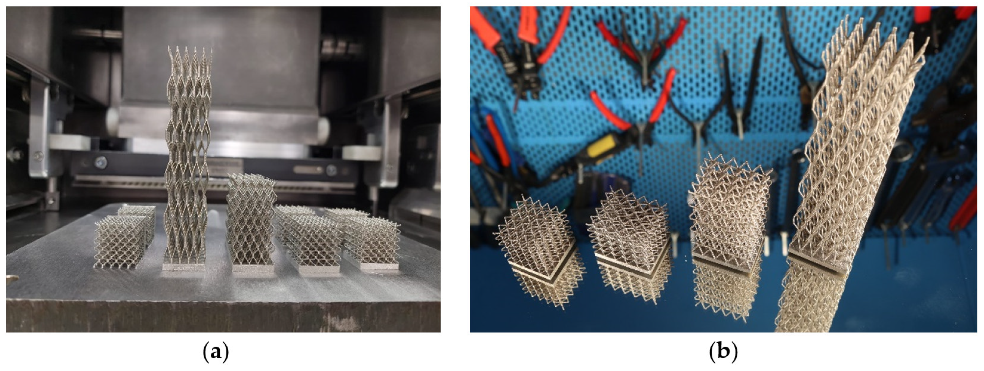
2.2.1. LB-PBF Lattice Structure Printing

The lattice structures are fabricated using a RenAM 400 machine (Renishaw, New Mills, UK), a state-of-the-art AM system designed for high-precision applications. The pieces are produced under a controlled argon atmosphere to ensure optimal material properties and avoid undesired oxidation. The printing parameters employed in this study are detailed in Table 2, which were optimized for the printing of lattice structures in a previous work [16]. The employed powder is Osprey® 718 (Sandvik, Stockholm, Sweden), manufactured via gas atomization and with a grain size between 15 and 53 µm [17].

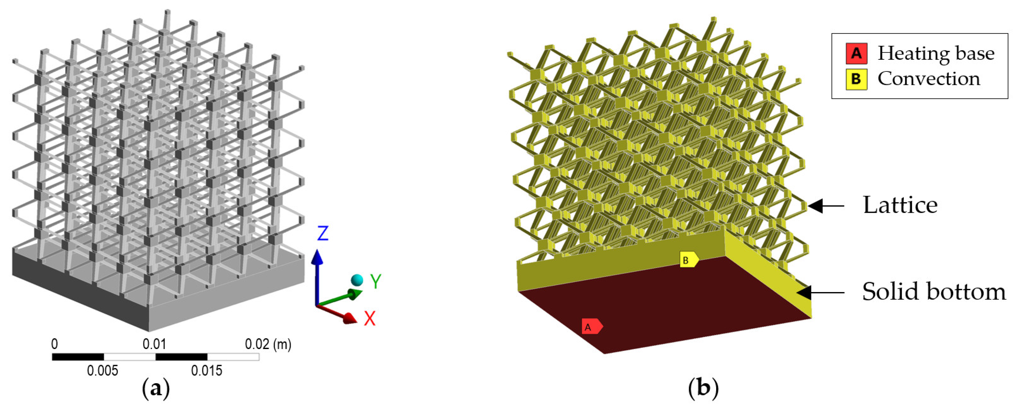
2.2.2. Simulation of the Lattice Structure

The transient thermal module of the commercial software Ansys Workbench 2023 R2 is employed for the simulation of the lattice structures and the equivalent solid blocks, which provides stable solutions to the 3D steady-state heat transfer problem. Four different cases are analyzed; all of them are printed in Inconel 718 and consist of a bcc lattice structure attached to a 2-mm-thick bottom plate. The bcc structure is selected, because it provides equal equivalent thermal conductivity in the X, Y, and Z directions when employing cubic cells [10], and it is possible to print it without support structures. The dimensions of the samples are indicated in Table 3. As an example, Figure 1a displays the geometry corresponding to case 1.
A constant heat flux is introduced from the lower face of the bottom plate and convection losses are considered in all faces of the lattice structure; see Figure 1b. The model considers temperature-dependent properties, which are experimentally measured as indicated in Section 2.1.
In the numerical simulations, unstructured tetrahedral meshes are generated for the lattice structures—see Figure 2a—whereas, for the solid block, hexahedral elements are selected—see Figure 2b. For both geometry types, a mesh independency study was carried out prior to the simulations to ensure the convergence and, thus, the validity of the results.

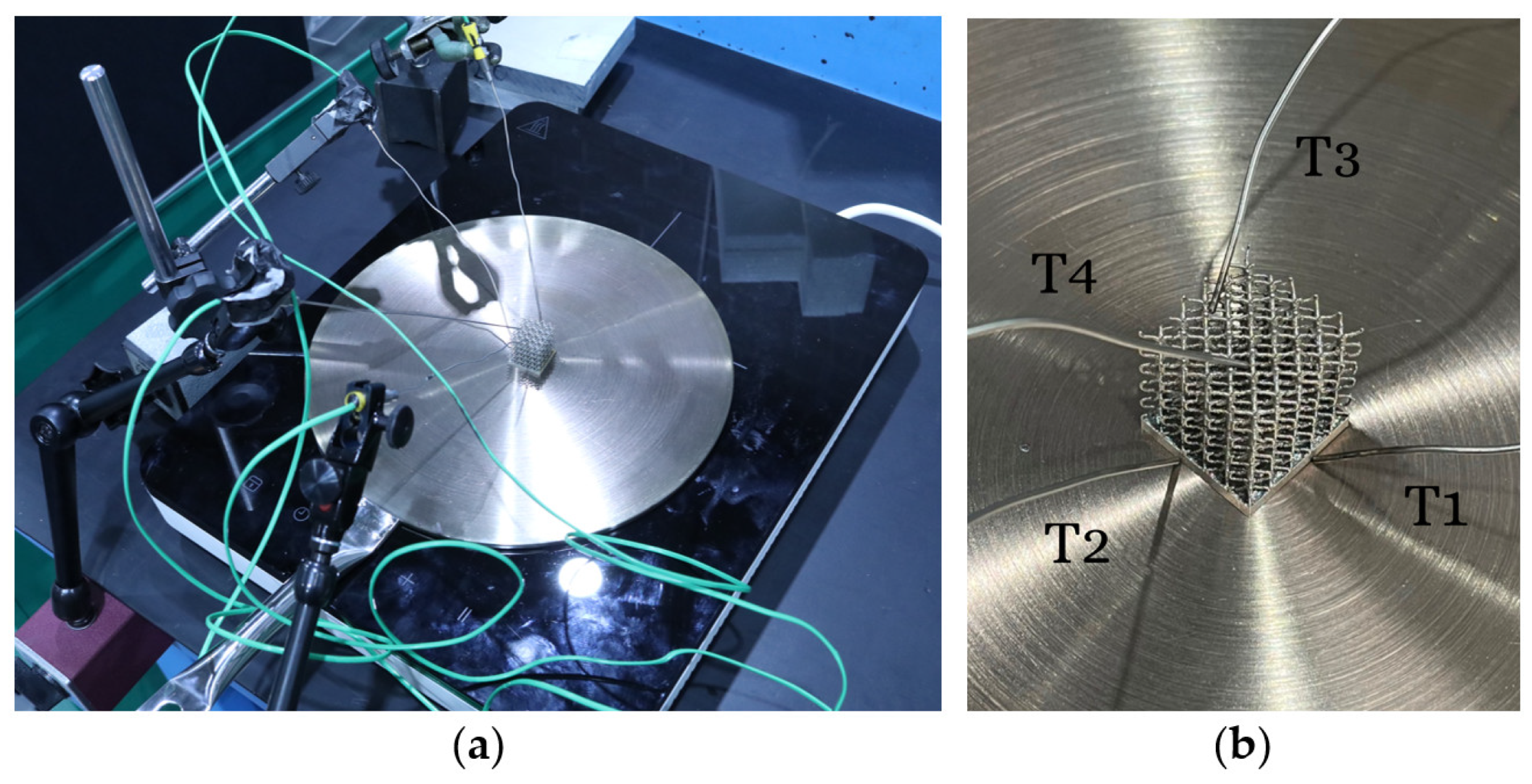
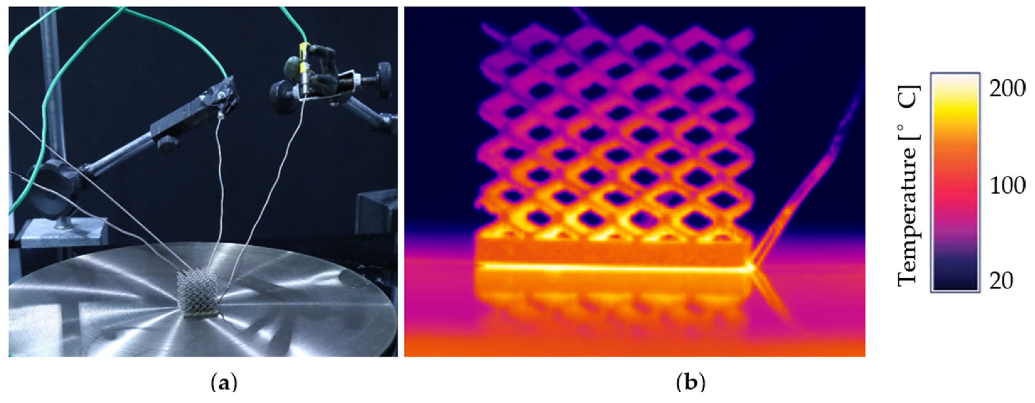
2.2.3. Experimental Testing

Convection Coefficient Determination

The lattice geometry is introduced in a Bentrup TC 504 oven (Rohde, Prutting, Germany) and heated until 250 °C at a 10 °C·min−1 rate. This temperature is held for 5 min to ensure the homogeneous heating of the sample. Afterwards, the component is extracted and positioned on a refractory surface that ensures that no heat is lost toward the contact surface. Hence, the only heat loss mechanism for the lattice structure is convection. Note that the radiation losses are not considered due to the relatively low temperatures of the samples studied; hence, their influence is included within the convection coefficient.
The cooling stage takes 300 s, which ensures that the sample is cooled down to room temperature, 22 °C, and, during this process, the temperature of the sample is continuously monitored. In this condition, the cooling process is controlled by Equation (2), where mlattice is the mass of the lattice [kg], cp is the specific heat [J·kg−1·K−1], T is the temperature of the lattice measured by the thermocouple [°C], h is the convection coefficient [W·m−2·K−1], Alattice is the area of the lattice in contact with the air [m2], and Troom is the room temperature [°C], which is monitored by a thermocouple positioned close to the lattice structure. This equation allows us to obtain a temperature-dependent convection coefficient as a function of the lattice temperature; see Equation (3). The lattice mass and area values are provided in Table 4.
m l a t t i c e · c p T · d T d t + h · A l a t t i c e · T T r o o m = 0
h T = m l a t t i c e · c p T · d T d t A l a t t i c e · T T r o o m

Heat Transfer Capability of the Lattice Structure

The lattice structures are manufactured with a solid plate attached to the base, which ensures that the lattice can be properly heated by means of an induction hob. The lattice is heated for 200 s at 2000 W power. Due to the non-magnetic nature of Inconel 718, a steel plate is mounted between both to ensure the heating of the Inconel 718 structure; see Figure 3a.
During the tests, four thermocouples are employed, with two positioned on the baseplate of the lattice structure and two on its top, as shown in Figure 3b. In this way, the average temperatures are extracted in order to compare them with the simulation values.
During the tests, a 22 °C constant room temperature is measured, which is also the initial temperature for the heating tests. In the air surrounding the lattice structure, there is no external ventilation or airflow, which ensures that the only heat dissipation mechanism of the lattice is natural convection. Moreover, the heating tests are monitored through an Optris PI thermal camera (Optris GmbH, Berlin, Germany), whose emissivity is adjusted with discrete thermocouple measurements; see Figure 4. In this way, the full thermal field of the lattice is defined.

3. Results

3.1. Thermal Properties of the Additively Manufactured Inconel 718

Inconel 718 cylinders are extracted using wire electro discharge machining (EDM) according to Table 1. Two samples are tested in each case, and the average property values are plotted in Figure 5. Material characterization is performed in the as-deposited condition, which is the same condition in which the lattice structures are tested in Section 3.3. Full details of the results are provided in Appendix A.
The diffusivity measurement shows a non-monotonic change above 700 °C, which is probably related to the formation of the δ phase. The precipitation processes of this harmful phase take place immediately after achieving the indicated limit temperature, and it affects negatively the properties of the material, including the thermal properties. This solid phase transformation is also identified in the DSC signal. As expected, the density of the material decreases during the heating due to the volume increase. The measured diffusivity values, as well as the thermal conductivity, are consistent with data from the literature for this material [18].

3.2. Lattice Structure Design and Part Printing

Initially, it is worth noting that the lattice geometries are designed using rectangular cross-section beams to eliminate the need for supports during printing. This is achieved by ensuring that the beam inclinations do not fall below 45°. Given that the structure comprises beams as small as 400 to 500 microns in width, it would have been impossible to remove any support material without causing damage to the structure.
These structures are generated by repeating a single unit cell a consistent number of times along all three spatial dimensions. Specifically, in this study, the unit cell is replicated five times in each direction, resulting in a total of 125 cells. The base lattice structure for case 1 measures 20 × 20 × 20 mm and consists of beams with a cross-sectional area of 0.4 × 0.4 mm. Variations of this geometry are created by applying different aspect ratios, specifically 1:1.25:1, 1:1.25:2, and 1:1.25:5.
The lattice structures are printed on a solid base that is approximately 3.5 mm thick, which is directly attached to the metal printing platform to mitigate any thermal deformation during the printing process; see Figure 6a. This support prevents warping and ensures the structural integrity of the printed components. After fabrication, the printed pieces are detached from the base using wire EDM, leaving a residual solid base of 2.00 mm beneath the lattice geometries.
In Figure 6a, the manufactured lattice structures inside the RenAM 400 PBF-LB machine are shown. For each case, two geometries are manufactured, and, once the repeatability of the machine is ensured, a single lattice for each case is analyzed, as shown in Figure 6b.

3.3. Experimental Study of the Lattice Structure

The experimental behavior of the lattice structure is evaluated in two situations. The first is cooling from a reference temperature in order to determine the convection coefficient of the lattice, and the second is heating from the baseplate to determine the heat transfer capabilities of the lattice structure.

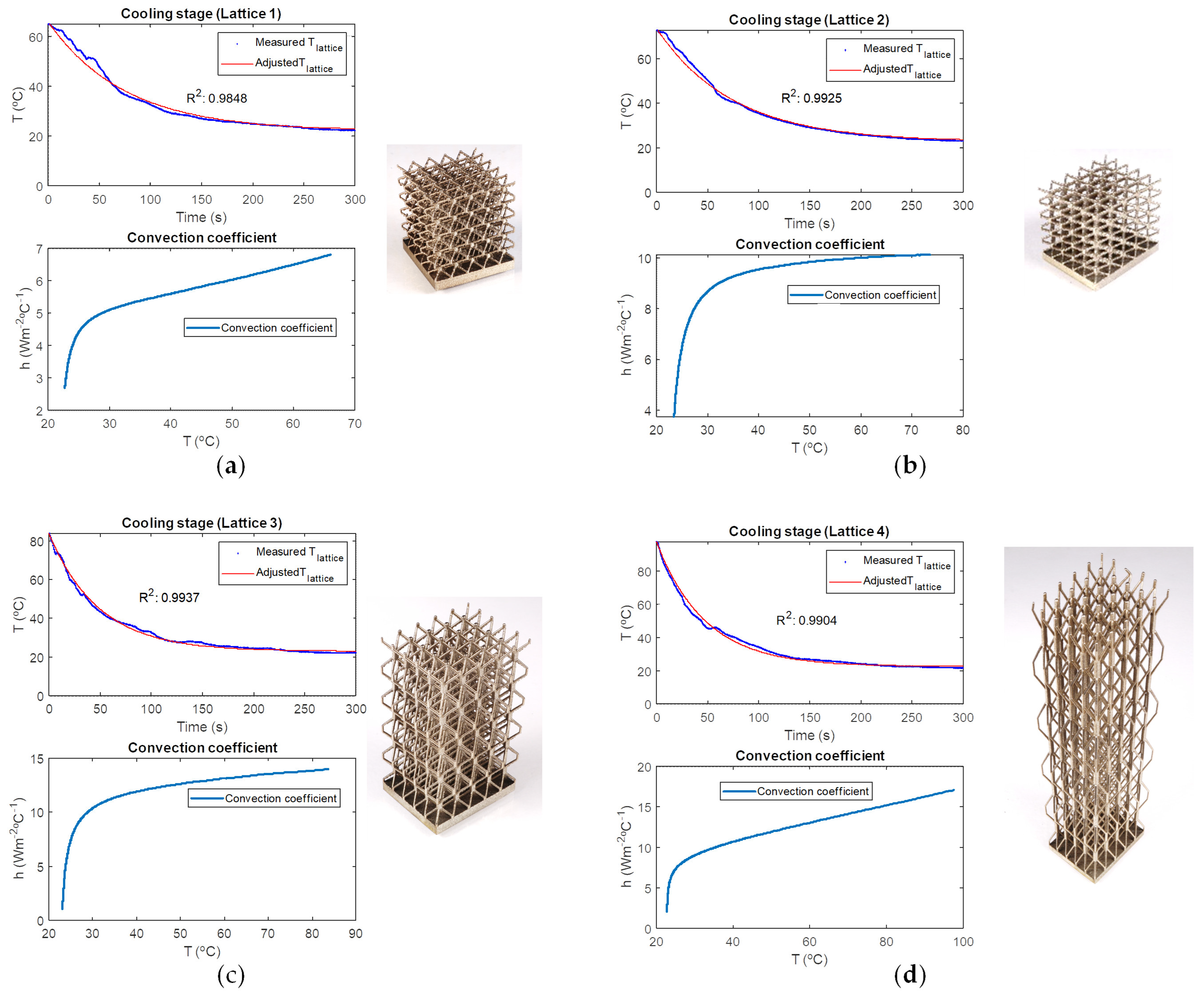
3.3.1. Convection Coefficient Determination

The low thermal inertia of the lattice structures produced by their low mass causes to rapidly decrease the temperature when they exit the oven. Consequently, although the sample’s positioning on the refractory surface and the thermocouple’s installation are performed as quickly as possible, the initial temperature for the cooling tests is between 60 and 100 °C. In Figure 7, the experimentally measured cooling stages of the four analyzed lattice structures are shown. Afterwards, employing the Matlab R2024b software, the cooling temperatures are approximated to an exponential negative function with a minimal error, R2, close to the unit value, named the Adjusted Tlatice and represented by the red line in Figure 7.
Once the Adjusted Tlattice and the experimentally measured Troom are obtained, they are introduced into Equation (3) to obtain the temperature-dependent convection. The value of the temperature-dependent convection coefficient is shown in the lower diagrams in Figure 7. Finally, the convection coefficient is approximated to a linear function for temperatures above 30 °C to introduce it in the Ansys Workbench model, as indicated in Figure 1. The equations for the linear convection coefficient, h(T), are shown in Table 5.
As can be seen, the more open the lattice structure is—see lattice 4—the more easily the air flows between the reticular struts and the higher the convection coefficient. Moreover, in case 2, a higher convection coefficient than in case 1 is obtained, which is logical considering that the lattice pattern has been extended in the Y direction.

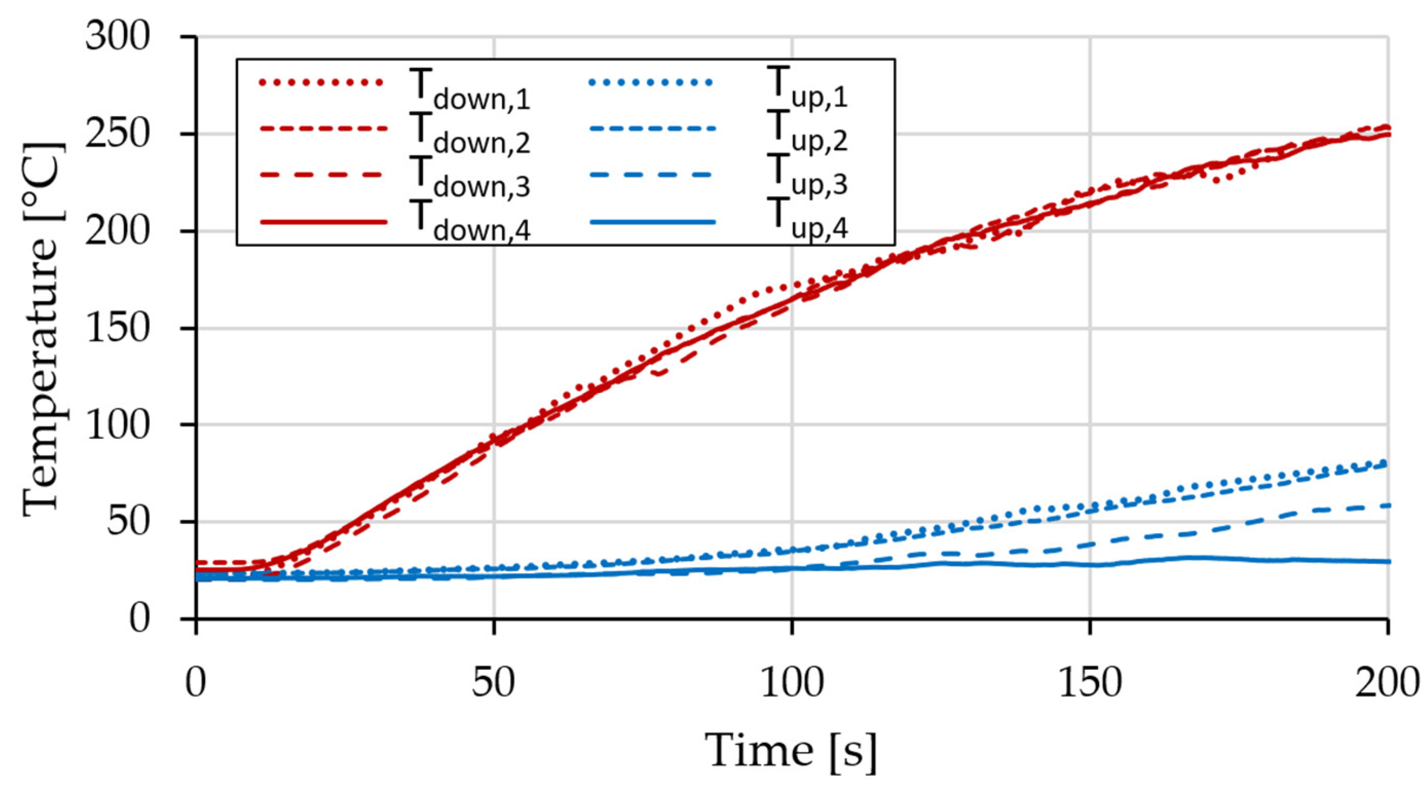
3.3.2. Heat Transfer Capabilities of the Lattice Structure

Based on the experimental setup depicted in Section 2.2.2, the evolution of the temperatures on the upper and lower faces of the lattice structures is measured; see Figure 8. In each lattice structure, the lower temperature, Tdown, is the average of the two thermocouples situated in the face in contact with the heated steel plate (T1 and T2), whereas the upper temperature, Tup, is the average of the two thermocouples situated in this plane (T3 and T4). In Figure 8, the numbers next to the measured temperatures indicate the tested lattice number.
In lattice 2, the temperature obtained in the upper face is almost the same as in lattice 1. This result is coherent, as the lattice height is the same in both cases. Moreover, the temperature reached in the lower face of the lattice structure depends mainly on the heat introduced by the inductor, and, in all cases, it presents a similar trend. Therefore, the validation of the simulations is performed based on the temperatures of the upper faces.

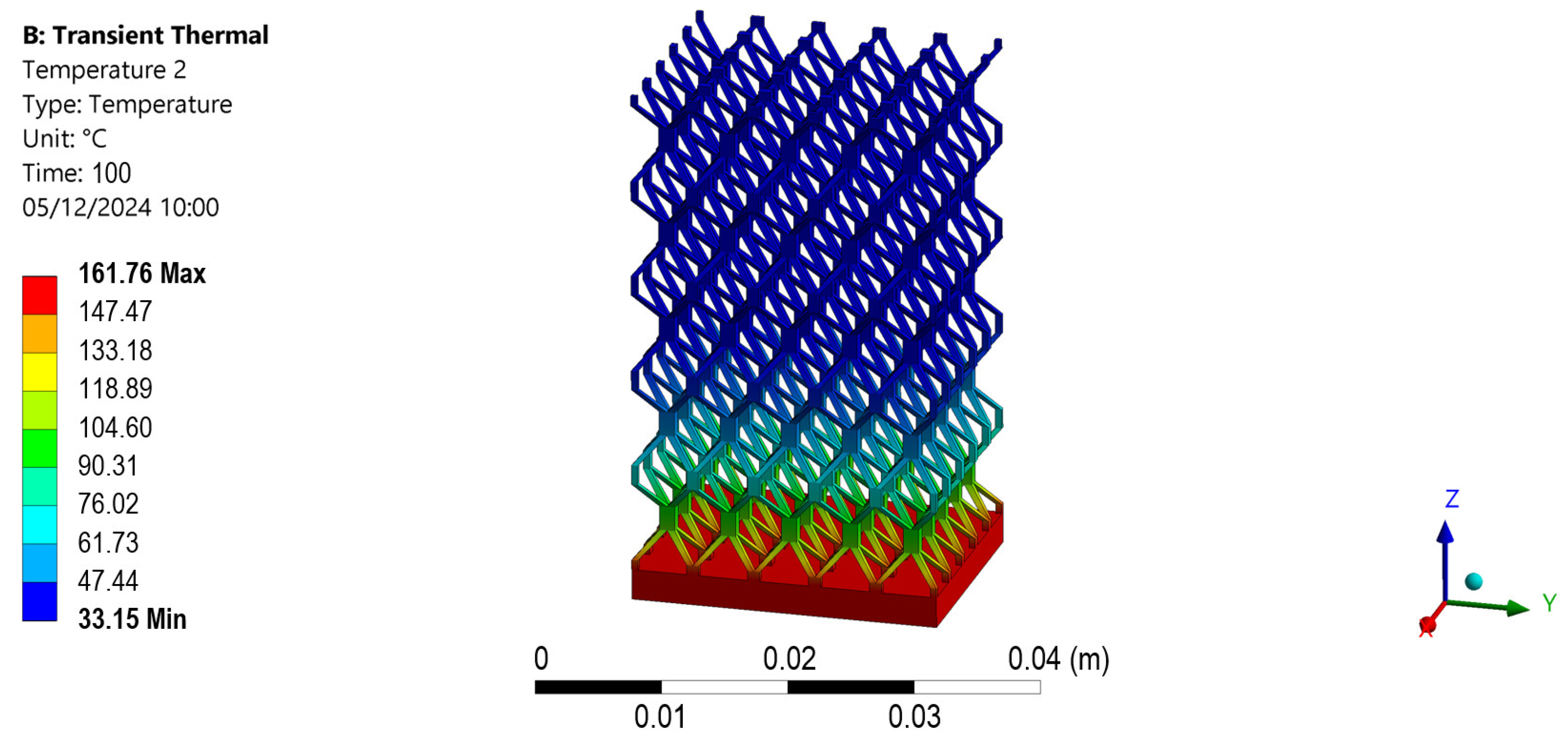
3.4. Thermal Simulation of the Lattice Structures

In the simulation of the lattice structures, the real properties of the Inconel 718 measured experimentally in Section 3.1 are introduced into the numerical thermal model. Moreover, the convection coefficient calculated in Section 3.3.1 is included as a function of the face temperature, and the baseplate temperature is imposed to match the real heating produced by the inductor hub. In Figure 9, the thermal field of lattice 3 is shown as an example.
The heating stage is compared with the thermal camera images and the thermocouple’s discrete measurements. Analogously to the experimental tests, the simulations are run for 200 s and the results are shown in Figure 10. As can be seen, the simulations present strong resemblance to the experimental tests, which justifies the validity of the employed methodology.

3.5. Approximation of the Lattice Structures Through Solid Bodies

Finally, the thermal behavior of the lattice structures is approximated by solid bodies. Following the same procedure as in the lattice structure simulation, in the solid bodies, the heat introduced by the induction hub is modeled by imposing the experimentally measured temperatures in the lower face of the geometry. In addition, the convection effect is included. However, as the convection indicates the heat dissipation per surface area, the lower area of the solid is compensated for by escalating the convection coefficient by an area ratio, R, defined according to Equation (4), where A l a t t i c e and A s o l i d are the external areas of the lattice and solid body, respectively.
R = A l a t t i c e A s o l i d
The approach of a lattice structure through a solid body implies that the density of the solid body needs to be reduced proportionally to the fill percentage of the lattice, which, in the present study, is 5.16% in all cases. Moreover, reducing the amount of material implies lowering the heat conduction capabilities of the body. Initially, the conduction coefficient was reduced in the same proportion as the fill percentage, i.e., 5.16%. However, the temperatures in the upper face were far too high—see the last column of Table 6—and this implied that the conduction coefficient needed to be further reduced.
The reduction in the conductivity coefficient of the solid block is iteratively calculated until an error below 2% regarding the lattice simulation is obtained. The conductivity reduction is named k% in Table 6, and, as can be seen, the more stretched the lattice structure is in the direction in which the heat is being transferred, the higher the effective conductivity of the equivalent solid block.
Based on the obtained low error rate between the simulated lattice and solid blocks, which is below 2% at the end of the 200 s simulation, it can be stated that the approach consisting of solid blocks with fictitious properties can be employed successfully to analyze the thermal behavior of complex lattice structures. In Figure 11, a comparison between the thermal fields for cases 3 and 4 is provided. As can be seen, strong resemblance is obtained in the thermal fields, not only in the temperatures of the upper and lower faces but also in its variation between them.
Consequently, the proposed geometrical simplification implies a minimum error but entails considerable savings in terms of the computational cost. As an example, in Table 7, the numbers of the performed simulations are detailed. In case 1, the resulting file size is reduced by 95% and the computational time by around 88%. Note that the execution time varies depending on the computer used, which, in the present case, was a DELL OPTI 7010 TOWER with a 13th Gen Intel® Core™ i7-13700 and 32 Gb RAM.
Moreover, it is concluded that, with lattice structures, it is possible to adjust the effective conductivity of the geometry, even if the same fill percentage factor is employed. This is especially interesting if variable conductivity regions are to be defined or anisotropic thermal behavior is desired, because it allows one to control the conductivity of the component without varying its weight.

4. Discussion

After the results are analyzed, in the present section, their relevance and implications are discussed; finally, the future research directions are indicated.
The main novelty of this research lies in the fact that lattice structures can be simulated as solid blocks with fictitious material properties that imitate the thermal behavior of the lattice structure. Considering the lattice structure as a solid material reduces not only the computational time required for the FEM simulation but also the size of the generated data. The specific heat of the fictitious material is the same as for the lattice material, but the density and thermal conductivity need to be adapted accordingly.
On the one hand, the density of the fictitious material is the same as that of the original material but is reduced according to the fill percentage. On the other hand, the conductivity reduction depends on both the fill percentage and the shape of the lattice structure. Therefore, for a certain fill percentage value, components with different thermal conductivities can be designed. Stretched lattices in the direction of heat transfer result in more efficient heat transfer. The limit case would be if the lattice were composed of columns in the direction of heat transfer. In this case, the effective thermal conductivity would match the fill percentage, whereas, in the perpendicular direction, the thermal conductivity would be zero. Theoretically, thanks to the lattice structures, the effective thermal conductivity of the structure could vary between zero and the fill fraction of the thermal conductivity of the solid block. Nevertheless, printing restrictions should be accounted for in order to avoid overhang areas that require support structures. Note that the limit for the use of support structures may depend on the employed machine’s characteristics.
Regarding the properties of the material employed to print the lattice structure, their values need to be defined in the FEM model. In the present research, the as-deposited Inconel 718 has been characterized, but, if the same material under different heat treatments or other materials are to be simulated, the FEM model would need to be fed with the corresponding material properties. However, the developed methodology would be still valid.
Therefore, the lattice structure behaves as a thermally anisotropic material, in which the effective thermal conductivity can be adjusted without modifying the weight of the part. This offers design engineers a new parameter to optimize their designs. Consequently, the next step would be to define the directional thermal conductivity of the lattice structures as a function of the fill percentage and the shape of the lattice, which could be introduced in topological optimization software.
In addition, the capability of FEM tools in simulating the thermal behavior of lattice structures is beyond doubt. However, if the movement of the air is not considered through a coupled CFD model, the definition of the convection coefficient is one of the most tedious tasks and generates great uncertainty in the results. In the present work, it has been experimentally determined by means of discrete temperature measurements during the cooling of the samples. Nevertheless, for larger parts or even lattice structures that are closed from the sides, the air circulation within the reticular structure would be limited and the effect of the convection could be eliminated from the simulation.

5. Conclusions

In this study, the capability of FEM tools to simulate the thermal behavior of lattice structures through solid bodies is analyzed. Based on the obtained results, the following conclusions are determined.
(1)
It is feasible to simulate the thermal behavior of lattice structures by means of solid blocks composed of fictitious materials whose properties have been adapted accordingly. An error rate below 2% is obtained between the simulated lattice and the solid block composed of the fictitious material.
  • The density of the fictitious material is proportional to the fill percentage of the lattice structure.
  • The specific heat of the fictitious material remains constant.
  • The effective thermal conductivity of the fictitious material needs to be adjusted based on the fill percentage and the shape of the lattice structure.
(2)
Thanks to the developed methodology, the computational cost required for the simulation of lattice structures can be reduced by up to 90%.
(3)
The convection coefficient is approximated as a linear function with regard to the temperature. The more stretched the lattice, the lower the resistance that it poses to the airflow and, therefore, the higher the convection coefficient. In order to consider the equivalent convection in the solid body, it has to be escalated according to the area ratio.
(4)
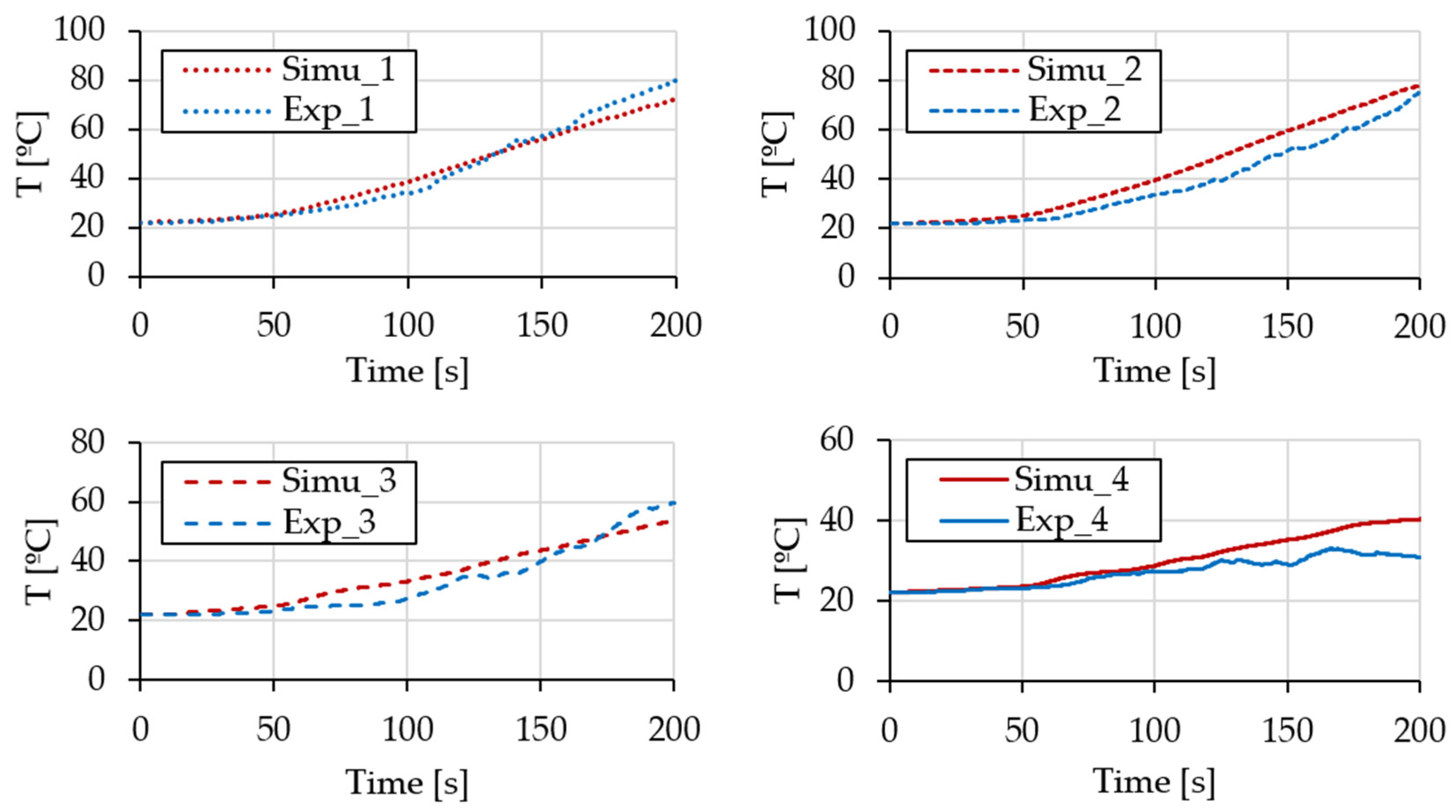
Once the convection coefficient has been adjusted experimentally, the thermal simulation of the lattice structures presents the same behavior as in the experimental tests.
(5)
Lastly, the obtained results open the door to the design of anisotropic components based on lattice structures and their topological optimization once the effective conductivity of a lattice structure is characterized.

Author Contributions

Conceptualization, J.I.A. and A.L.; methodology, J.I.A.; software, J.I.A., X.A. and J.L.; validation, G.G., J.I.A., S.S., L.G., X.A. and J.L.; formal analysis, X.A. and J.L.; investigation, S.S., L.G., J.I.A., X.A. and J.L.; resources, A.L.; data curation, X.A. and J.L.; writing—original draft preparation, J.I.A.; writing—review and editing, all authors; funding acquisition, J.I.A. and A.L. All authors have read and agreed to the published version of the manuscript.

Funding

This research was funded by the Basque Government through the ELKARTEK program, grant number KK-2023/00096, and by the MCIN/AEI/10.13039/501100011033/ and ERDF A way of making Europe, grant PID2022-141946OB-C21.

Institutional Review Board Statement

Not applicable.

Informed Consent Statement

Not applicable.

Data Availability Statement

Data are contained within the article.

Conflicts of Interest

The authors declare no conflicts of interest.

Appendix A

Table A1. Tabular data on the average measured properties of Inconel 718 in the as-deposited condition.
Temp. [°C]Diff. (mm2·s−1)Dens. (g·cm−3)Cp (J·kg−1·K−1)K (W·m−1·K−1)
503.0778.200462.34511.666
1003.2088.180464.06012.178
2003.5048.140489.66513.965
3003.8038.110506.02015.605
4004.0568.070512.16516.762
5004.2938.030547.67018.880
6004.5407.990634.02522.999
7004.8627.960627.00024.266
8004.7007.920722.96526.912
9004.7437.880602.06522.502
10005.0267.860424.23518.732

References

  1. Gloria, A.; Montanari, R.; Richetta, M.; Varone, A. Alloys for Aeronautic Applications: State of the Art and Perspectives. Metals 2019, 9, 662. [Google Scholar] [CrossRef]
  2. Yang, W.; He, W.; Hu, Z.; Duan, W.; Ni, X.; Deng, X.; Wang, A.; Luo, Y.; Xie, F.; Chen, Z.; et al. Fabrication of Inconel 718 composites reinforced with TiCN via laser powder bed fusion: Integration of triply periodic minimal surface lattice structures. J. Mater. Res. Technol. 2024, 32, 2443–2458. [Google Scholar] [CrossRef]
  3. Beyer, C.; Figueroa, D. Design and Analysis of Lattice Structures for Additive Manufacturing. J. Manuf. Sci. Eng. 2016, 138, 121014. [Google Scholar] [CrossRef]
  4. Chowdhury, S.; Yadaiah, N.; Prakash, C.; Ramakrishna, S.; Dixit, S.; Gupta, L.R.; Buddhi, D. Laser powder bed fusion: A state-of-the-art review of the technology, materials, properties & defects, and numerical modelling. J. Mater. Res. Technol. 2022, 20, 2109–2172. [Google Scholar] [CrossRef]
  5. Popovich, V.A.; Borisov, E.V.; Popovich, A.A.; Sufiiarov, V.S.; Masaylo, D.V.; Alzina, L. Functionally graded Inconel 718 processed by additive manufacturing: Crystallographic texture, anisotropy of microstructure and mechanical properties. Mater. Des. 2017, 114, 441–449. [Google Scholar] [CrossRef]
  6. Flores, I.; Kretzschmar, N.; Azman, A.H.; Chekurov, S.; Pedersen, D.B.; Chaudhuri, A. Implications of lattice structures on economics and productivity of metal powder bed fusion. Addit. Manuf. 2020, 31, 100947. [Google Scholar] [CrossRef]
  7. Mahshid, R.; Hansen, H.N.; Højbjerre, K.L. Strength analysis and modeling of cellular lattice structures manufactured using selective laser melting for tooling applications. Mater. Des. 2016, 104, 276–283. [Google Scholar] [CrossRef]
  8. Leary, M.; Mazur, M.; Williams, H.; Yang, E.; Alghamdi, A.; Lozanovski, B.; Zhang, X.; Shidid, D.; Farahbod-Sternahl, L.; Witt, G.; et al. Inconel 625 lattice structures manufactured by selective laser melting (SLM): Mechanical properties, deformation and failure modes. Mater. Des. 2018, 157, 179–199. [Google Scholar] [CrossRef]
  9. Sajjad, U.; Rehman, T.U.; Ali, M.; Park, C.W.; Yan, W.M. Manufacturing and potential applications of lattice structures in thermal systems: A comprehensive review of recent advances. Int. J. Heat Mass Transf. 2022, 198, 123352. [Google Scholar] [CrossRef]
  10. Piacquadio, S.; Schirp-Schoenen, M.; Mameli, M.; Filippeschi, S.; Schröder, K.U. Experimental analysis of the thermal energy storage potential of a phase change material embedded in additively manufactured lattice structures. Appl. Therm. Eng. 2022, 216, 119091. [Google Scholar] [CrossRef]
  11. Gao, T.; Zhang, W.H.; Zhu, J.H.; Xu, Y.J.; Bassir, D.H. Topology optimization of heat conduction problem involving design-dependent heat load effect. Finite Elem. Anal. Des. 2008, 44, 805–813. [Google Scholar] [CrossRef]
  12. Iga, A.; Nishiwaki, S.; Izui, K.; Yoshimura, M. Topology optimization for thermal conductors considering design-dependent effects, including heat conduction and convection. Int. J. Heat Mass Transf. 2009, 52, 2721–2732. [Google Scholar] [CrossRef]
  13. Yamada, T.; Izui, K.; Nishiwaki, S. A Level Set-Based Topology Optimization Method for Maximizing Thermal Diffusivity in Problems Including Design-Dependent Effects. J. Mech. Des. 2011, 133, 031011. [Google Scholar] [CrossRef]
  14. Zhou, Y.; Shen, S.; Liu, T.; Li, P.; Duan, F. Effective heat conduction evaluation of lattice structures from selective laser melting printing. Int. J. Heat Mass Transf. 2024, 218, 124790. [Google Scholar] [CrossRef]
  15. Foteinopoulos, P.; Papacharalampopoulos, A.; Stavropoulos, P. Additive manufacturing simulations: An approach based on space partitioning and dynamic 3D mesh adaptation. Addit. Manuf. Lett. 2024, 11, 100256. [Google Scholar] [CrossRef]
  16. Pérez-Ruiz, J.; González-Barrio, H.; Sanz-Calle, M.; Gómez-Escudero, G.; Munoa, J.; de Lacalle, L.L. Machining stability improvement in LPBF printed components through stiffening by crystallographic texture control. CIRP Ann. 2023, 72, 141–144. [Google Scholar] [CrossRef]
  17. Certificate of Analysis, Osprey® 718. Available online: https://www.metalpowder.sandvik/globalassets/webshop/osprey-718/certificate-of-analysis-osprey-718-53-15.pdf (accessed on 23 January 2025).
  18. Terpilowski, J.; Józwiak, S.; Woroniak, G.; Szczepaniak, R. Thermal Diffusivity Characteristics of the IN718 Alloy Tested with the Modified Pulse Method. Materials 2022, 15, 7881. [Google Scholar] [CrossRef] [PubMed]
Figure 1. (a) Design of the lattice cells, case 1, and (b) the applied boundary conditions for the simulation.
Applsci 15 01372 g001
Figure 2. Mesh comparison for (a) lattice 1 and (b) the equivalent solid block 1.
Applsci 15 01372 g002
Figure 3. (a) Experimental setup for the lattice heating and (b) positioning of the four thermocouples employed to monitor the heating cycle: two on the base (T1 and T2) and two on the upper face (T3 and T4).
Applsci 15 01372 g003
Figure 4. Temperature measurements in the lattice heating tests: (a) discrete temperatures using thermocouples and (b) temperature field obtained by means of a thermal camera.
Applsci 15 01372 g004
Figure 5. Thermal properties of Inconel 718: (a) specific heat, (b) thermal diffusivity, and (c) density.
Applsci 15 01372 g005
Figure 6. Manufactured lattice structures: (a) inside the RenAM-400 PBF-LB machine attached to the printing plate; (b) final components removed from the plate.
Applsci 15 01372 g006
Figure 7. Temperature monitoring during the cooling stage and the corresponding convection coefficient: (a) lattice 1, (b) lattice 2, (c) lattice 3, and (d) lattice 4.
Applsci 15 01372 g007
Figure 8. Experimentally measured temperatures in the upper and lower faces for lattices 1–4.
Applsci 15 01372 g008
Figure 9. Thermal field during the simulation of lattice 3 at the time step t = 100 s.
Applsci 15 01372 g009
Figure 10. Temperatures of the upper faces for the simulated and experimental tests.
Applsci 15 01372 g010
Figure 11. Comparison between the thermal results in case 3 at t = 200 s time step ((a) solid block and (b) lattice structure) and case 4 at t = 200 s time step ((c) solid block and (d) lattice structure).
Applsci 15 01372 g011
Table 1. Equipment employed to measure the thermal properties and dimensions of Inconel 718 samples.
EquipmentMeasured PropertySample Dimensions (mm)
Linseis L75 Platinum DilatometerDensity ( ρ )Ø 5 × 15
MicroFlash® 457 Laser FlashThermal diffusivity ( α )Ø 10 × 3
449 F3 Jupiter DSC STASpecific heat ( c p )Ø 5 × 1
Table 2. Printing parameters used in Inconel 718 sample manufacturing.
ParameterValue
Hatch distance [µm]80
Layer thickness [µm]60
Laser power [W]200
Inert gas [-]Argon
Scan speed (mm·s−1)1250
Table 3. Dimensions of the lattice structures and solid blocks for the studied cases.
CaseDimensions X × Y × Z [mm3]Fill %Lattice Volume [mm3]Baseplate
Volume [mm3]
Solid Block Volume [mm3]
120 × 20 × 205.16613.198008800
220 × 25 × 205.16766.49100011,000
320 × 25 × 405.161282.15100021,000
420 × 25 × 1005.162829.64100050,000
Table 4. Physical properties of the lattices required to obtain the convection coefficient.
Casemlattice (kg)Alattice (m2)
10.01250.0049
20.01610.0059
30.01950.0084
40.03060.0174
Table 5. Temperature-dependent convection coefficient approximated to a linear function.
Caseh(T) (W·m−2·K−1)
10.05·T + 3.5
20.05·T + 6.5
30.10·T + 6.0
40.133·T + 5.0
Table 6. Thermal results of solid block simulations.
CaseRLattice
Experimental
T [°C]
Lattice
Simulation
T [°C]
Solid Block
Simulation
T [°C]
Solid Block
Error
[%]
k%Solid Block
Simulation T [°C]
If k = Fill %
12.2780.7977.0877.580.650.98%131.80
22.3677.1478.0777.10−1.241.85%128.01
31.9658.6453.8854.951.992.85%69.57
41.7929.8240.3840.060.544.00%46.38
Table 7. Computational cost for the lattice and solid geometry simulations for the different cases.
CaseLatticeSolid
Number of
Elements
Elapsed TimeMAPDL Result
File Size
Number of
Elements
Elapsed TimeMAPDL Result File Size
141,9932 h 3 min89.698 GB206615 min 11 s4.47 GB
242,5302 h 6 min92.439 GB205418 min 5 s3.80 GB
335,8481 h 41 min88.872 GB301621 min 34 s5.27 GB
443,6312 h 12 min112.02 GB273623 min 15 s7.16 GB
Disclaimer/Publisher’s Note: The statements, opinions and data contained in all publications are solely those of the individual author(s) and contributor(s) and not of MDPI and/or the editor(s). MDPI and/or the editor(s) disclaim responsibility for any injury to people or property resulting from any ideas, methods, instructions or products referred to in the content.

