Root Cause Analysis of a Collapse in a Hydropower Tunnel
Abstract
Featured Application
Abstract
1. Introduction
1.1. Overview
- Detailed geological mapping and observations of rock conditions within the by-pass tunnel at the location of the same geological sequence as the collapse zone of the main power tunnel;
- Geotechnical drilling and core logging from an array of holes drilled from the upstream side of the collapse in the main tunnel;
- Collection of samples from the bore holes around the main tunnel and by-pass tunnel for XRD testing, clay-sized speciation testing, petrographic examination, and swell pressure testing;
- Detailed mapping of the debris pile as the failure debris material was removed downstream of the collapse.

1.2. Collapse and Key Observations
- Hydrothermally altered red tuffs (HARTs);
- Andesitic agglomerates (AAs);
1.3. Tunnel Design, Construction, and Support Levels
2. Geological Observations and Interpretation
2.1. Collapse Zone Geological Observations
2.2. Downstream Observations
3. Factors That Contributed to the Catastrophic Failure
3.1. Structural, Geological, and Lithological Factors
- (1)
- Hydrothermally altered red tuff (HART) upstream of the collapse zone;
- (2)
- HART within the FDZ and crystal lithic tuff (CLT within the FDZ and AA within the FDZ;
- (3)
- Andesitic agglomerates (AAs) downstream of the collapse.

- Intact HART in the drill cores that were examined and tested have UCS values of around 25 MPa;
- AA cores have UCS values of around 75 MPa.
3.2. Mineralogical Factor
3.2.1. XRD Testing and Petrographic Examination
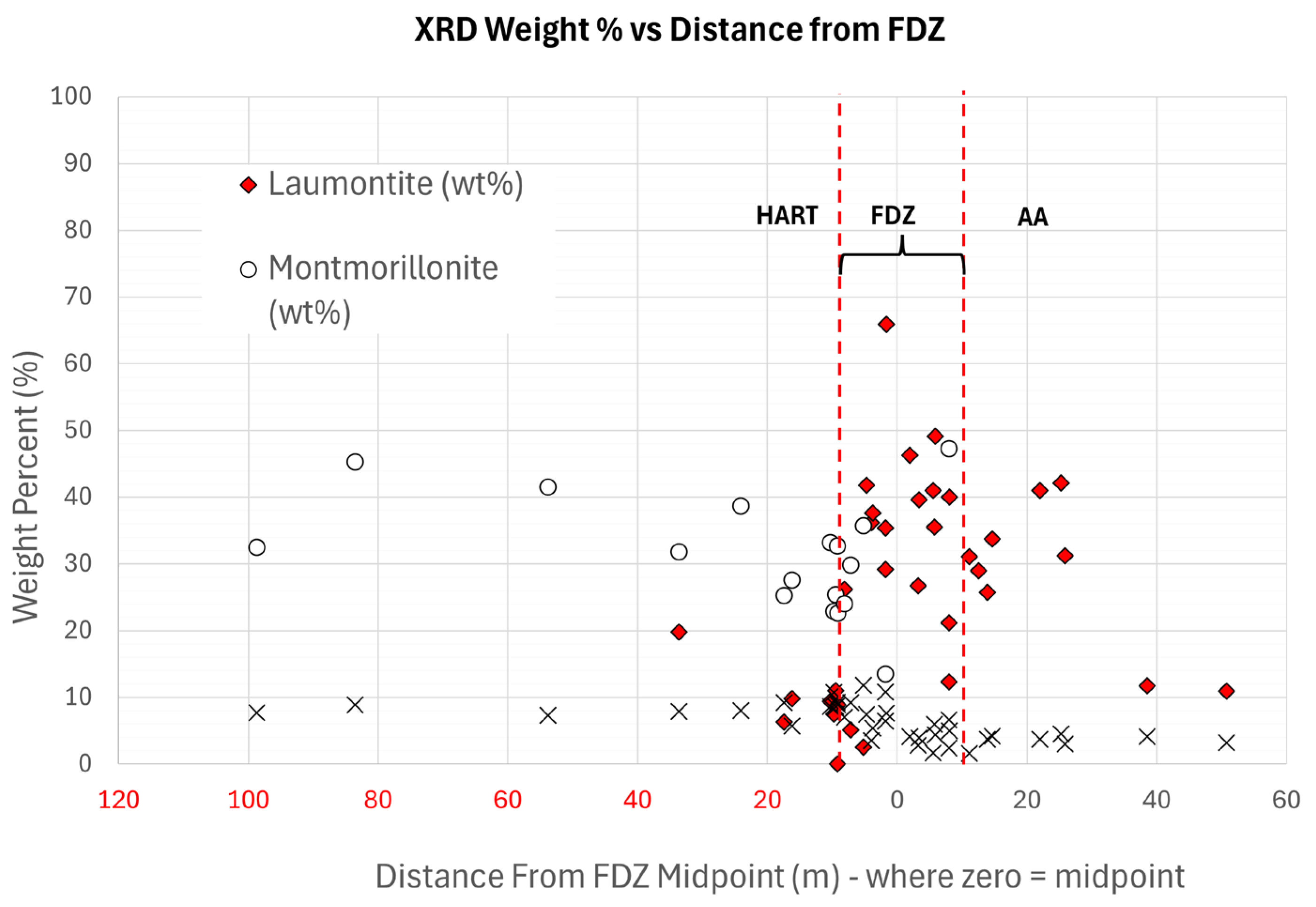
- As shown in Figure 9 and Figure 10, the upstream HART rock has very little to no laumontite (and are therefore not reactive to dehydration and disintegration—see [21]) but has very high percentages of montmorillonite—a swelling clay [2,3,4,5,6,7,8,10]. As discussed above, despite the presence of montmorillonite in the HART rocks upstream of the collapse, these tuffs were not affected during the collapse (i.e., montmorillonite was only elevated outside the collapse zone);
- The AA rocks downstream of the FDZ also have an elevated presence of laumontite (Figure 9 and Figure 10), and it is known from petrographic studies of the RCA that the laumontite in AA rocks is present primarily as an alteration product of plagioclase in euhedral mineral grains and (welded) grain-supported rock fragments. The significance of this is that laumontite in the crystals is largely protected to exposure to air or water and therefore is not as prone to desiccation or swelling;
- In the FDZ rocks, laumontite is abundant in interconnected ubiquitously developed veins and in the fine-grained clay-sized matrix between the veins. Unlike the AA rocks, these laumontite-rich veins and fractures are not protected from exposure to air or water.
- When exposed to air (during construction and during successive collapses), the laumontite in the veins loses water and desiccates, causing shrinkage cracks followed by the disaggregation of the FDZ rock as a whole. Ref. [21] confirms that dehydration causes the disintegration of laumontite;
- Conversely, leonhardite can expand (although not to the same degree as montmorillonite) as it acquires crystal water through wetting and can revert back to laumontite [21].
- XRD testing and petrographic examination in and around the collapse also showed that laumontite is preferentially deposited in veins in the FDZ, and this may be related to differing temperatures and pressure conditions within the FDZ rocks during faulting based on review and knowledge gained from [30,31,32,33,34,35,36,37,38]. While it is beyond the scope of this paper, readers interested in detail on the effect of temperature, pressure condition, and stability conditions for zeolites and other low grade metamorphic mineral are recommended to review [30,31,32,33,34,35,36,37,38];
- This is in contrast to the HART rocks, in which several species of zeolite, namely wairakite and analcime, and a very low percentage of laumontite are present in veins;
- Wairakite, analcime, and other zeolites are present but are much less susceptible to desiccation [21], which is likely why the HART rocks have higher swell potential than the FDZ rocks (due to montmorillonite absorbing water, see [1,2]) but do not disintegrate like the FDZ rocks. It is also apparent that a lot of the veins present in the HART rocks contain phyllosilicates that are not expansive clays, e.g., chlorite and muscovite;
- The high montmorillonite percentages found in the HART rocks occur primarily in the very fine-grained matrix material, and the matrix material is bound together with hematite and other metallic oxides that may slow down the rate of swelling;
- The significance of this is that while minor laumontite is present in the HART rock, it is likely less available to air or water exposure compared to the FDZ rocks. While the HART rocks are prone to swelling because of the high montmorillonite content, this is likely a relatively slow process due to the lower permeability of the HART rocks [10];
- Laumontite is present in similar percentages in both the FDZ rocks and the AA rocks. Analysis showed that laumontite is locked into the welded rock fragments and altered plagioclase crystals in the AA rocks, and therefore, only a small proportion of the laumontite is available to react with air. While mostly below detection levels, montmorillonite is also likely present in the AA matrix but is again not readily available to react with water because the matrix material between the rock particles is typically not connected (based on thin section observations), thereby resulting in a fairly inert rock that is not prone to swelling.
3.2.2. Laumontite and Swelling Clay: Experience on Another Project
3.2.3. Swelling Pressures in Support of Mineralogical Factors
- Constant volume swelling pressure tests carried out in the laboratory on powdered rock samples. These data are referred to as expansion swell pressures (ESPs); and
- Use of a project-specific correlation between swelling pressures and the ethylene glycol (EG) state and liquid limit (LL). These data are referred to as chart (EG/LL) design swell pressures (CDPs) in this paper.
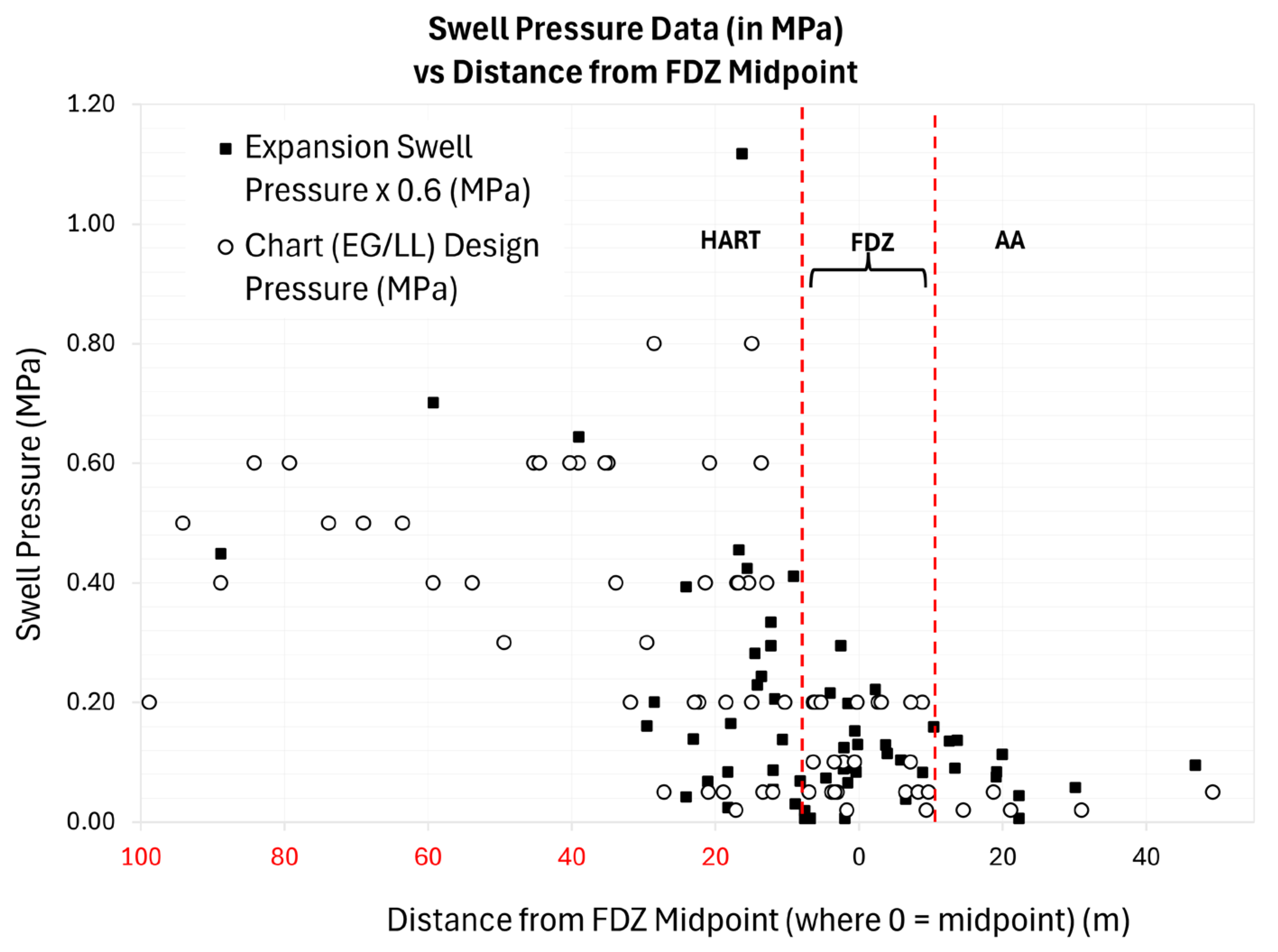
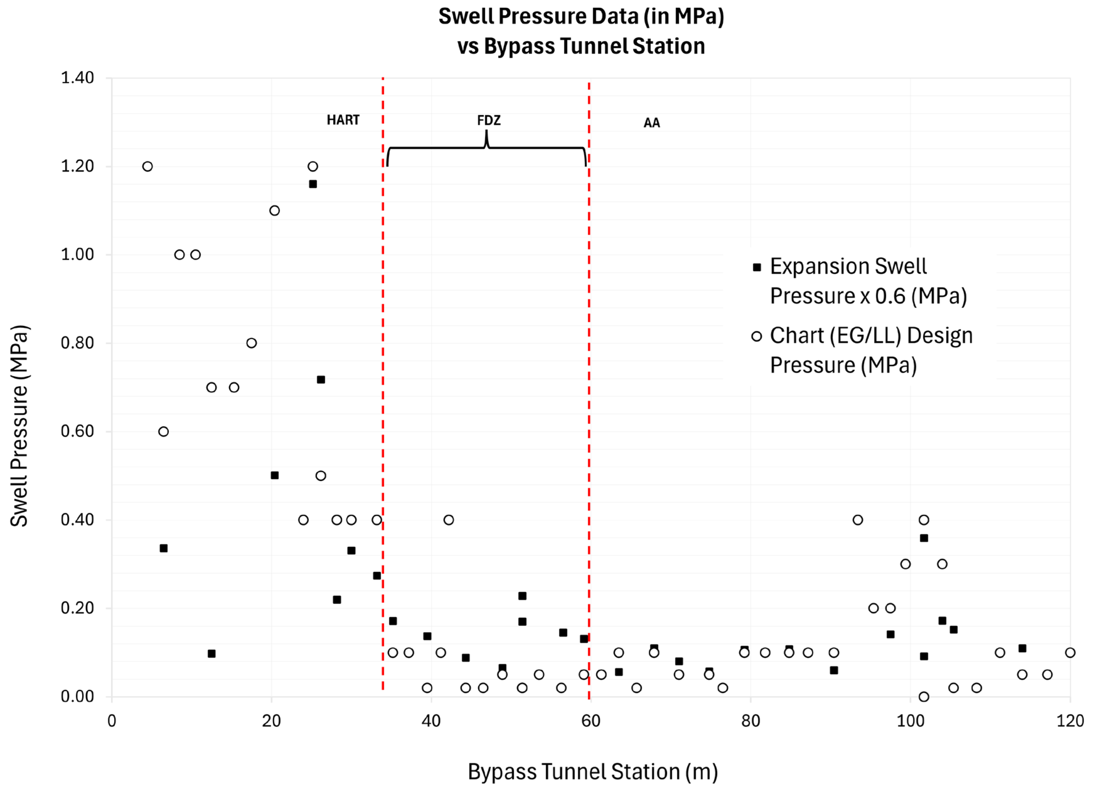
- The swell pressures are highest in the HART rocks and close to or at the transition into the FDZ. The average swell pressure (average of both ESP and CDP results combined) in this zone is approximately 0.64 MPa in the by-pass tunnel and 0.4 MPa in HART rocks upstream of the collapse zone. It is apparent when these results are compared with the mineralogical plots that HART rocks have the highest swelling clay percentages and the lowest zeolite (laumontite) percentages;
- It is clear from these data that the measured swell pressures are directly proportional to the recorded swelling clay content, i.e., the higher the swelling clay content, the higher the swell pressure.
3.3. Over Stressing Factor
3.3.1. Stress Downstream of the Collapse
3.3.2. Stress in the Fault-Damaged Zone (FDZ)
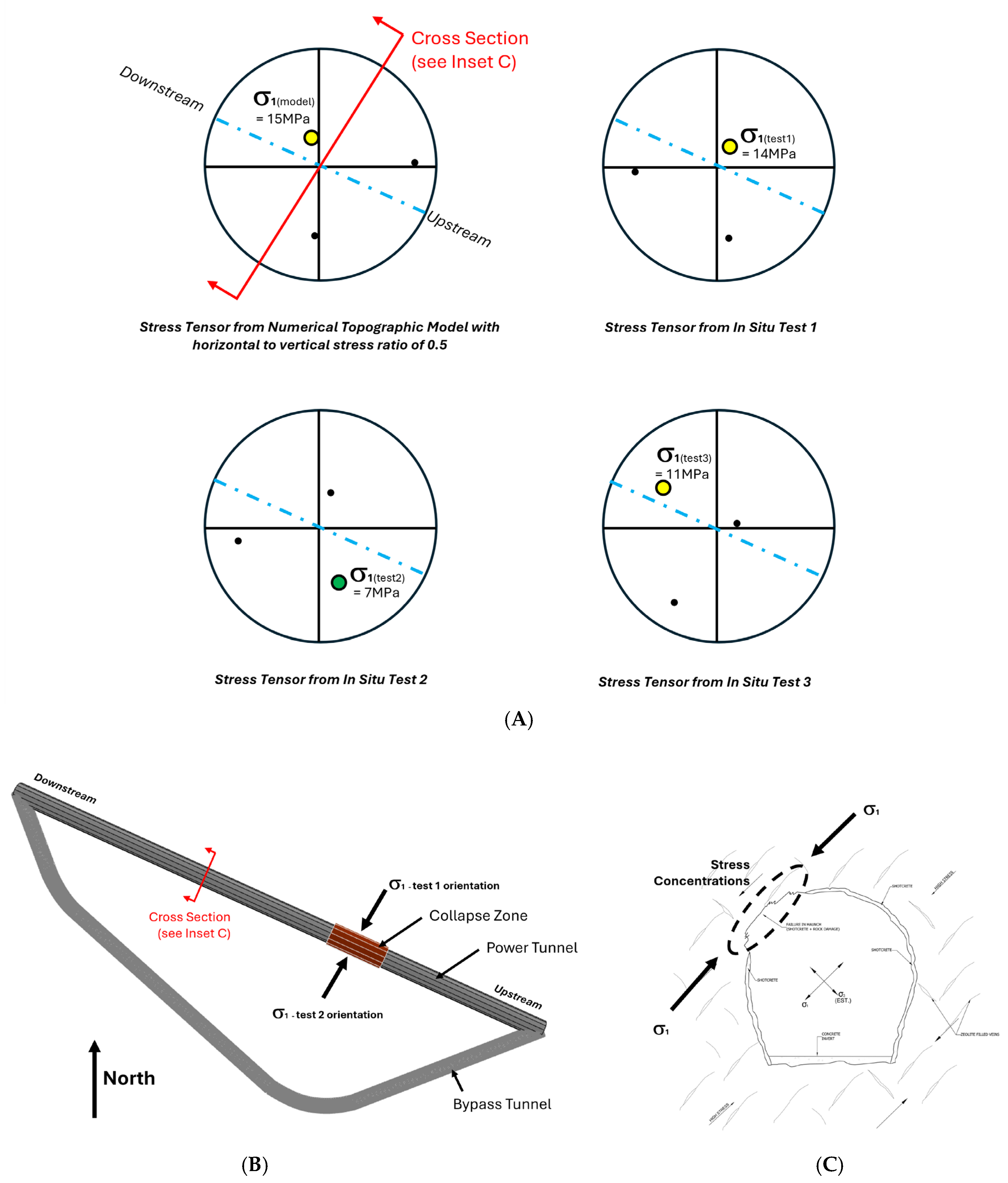
3.3.3. In Situ Stress Measurements
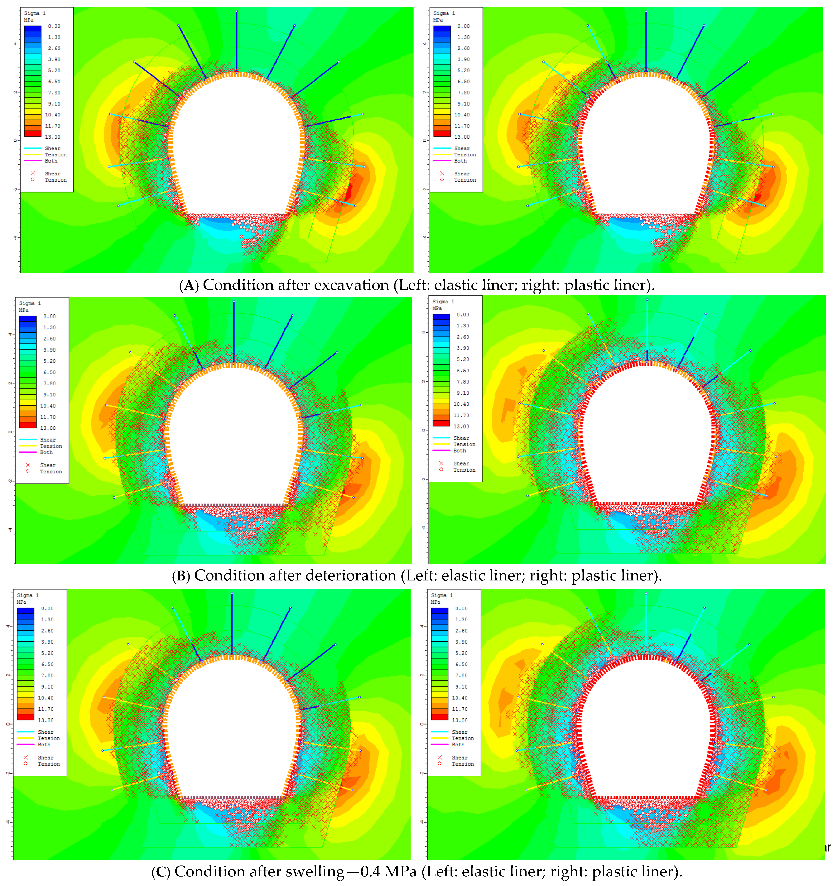
3.3.4. Back Analysis of the Collapse Zone
4. Successive Failures and the Additive Effect of Tunnel Pressure Changes
- As described in Section 3.2.3 and Figure 11 and Figure 12, the swell pressures are highest in the HART rocks and close to or at the transition into the FDZ. It is also apparent when these results are compared with the mineralogical plots (Section 3.2.1 and Figure 9 and Figure 10) that the HART rocks have the highest swelling clay percentages and the lowest laumontite percentages;
- The tunnel is below the hydraulic grade line [22], so the tunnel would have been under positive pressure during operations;
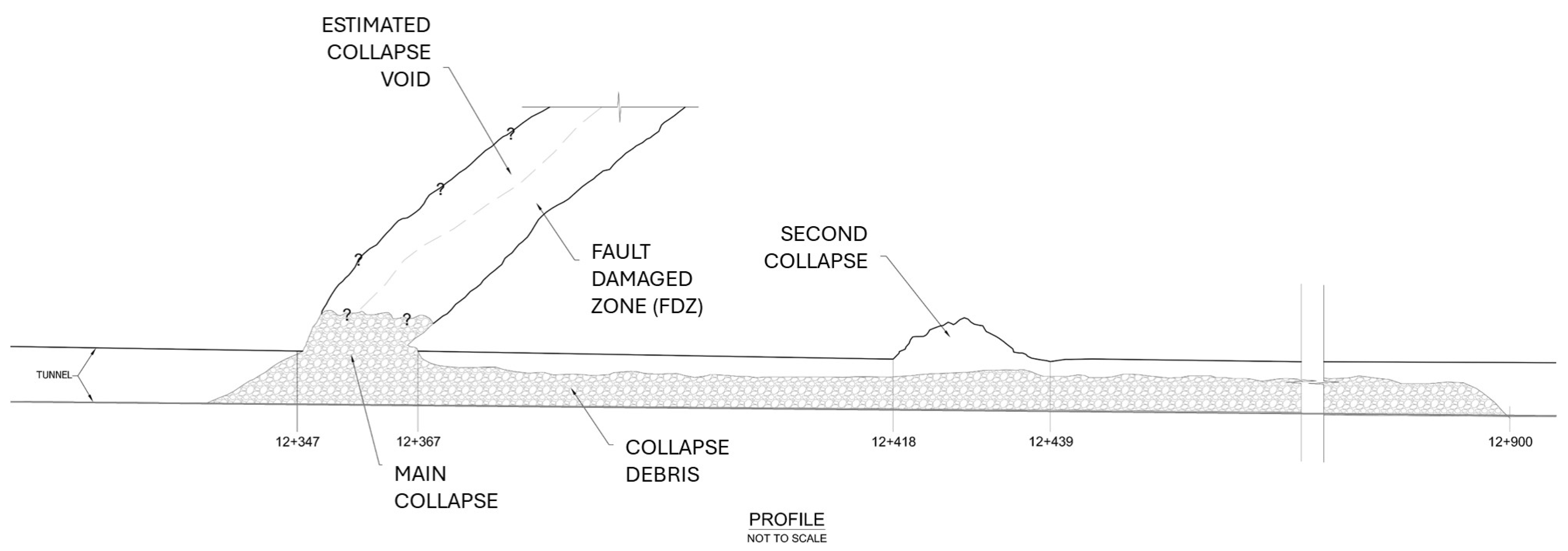
- When the initial and successive rockfalls occurred and partially blocked the tunnel, the velocities above a particular partial blockage would have increased significantly, and the higher velocity would be able to transport material downstream from the collapse zone. This material was deposited downstream of the blockage, where the velocity drops, as shown in Figure 1 and Figure 6. This process continued as the collapse propagated upwards and more material collapsed in a series of rockfalls, with the higher flow velocities preventing the collapse zone from fully “choking” and stopping water flow. This is believed to be part of the reason why the volume of the collapse debris is so great;
- After each rockfall occurred and the tunnel partially filled with debris (as shown in Figure 7), the velocity increased at the collapse (partial choke point) as described above. This would have had the effect of lowering the pressure in the tunnel via the Venturi effect. The pore pressure in the rock (in particular, in the FDZ) would remain the same as before the collapse, so the differential pressure would destabilize the material in the fault-damaged zone, causing further collapse;
- At the final blockage, the tunnel downstream of the collapse is understood to have briefly completely drained downstream of the collapse; thus, the pressure in this section of the tunnel would have been lowered to atmospheric pressure or less. This unplanned depressurization would further result in a pressure differential between the rock around the tunnel and the interior of the tunnel, which would exacerbate the shotcrete and rock spalling. This may have caused the downstream so-called ‘second collapse zone’(Figure 1) in conjunction with the relatively high in situ stress field, where the fall-out material was observed to be sitting on top of the debris from the main collapse. While it is not known when individual rockfalls occurred, it is understood that the blockages only became significant enough to be detected in the degraded performance of the scheme a few days prior to the shutdown.
5. Conclusions
Author Contributions
Funding
Institutional Review Board Statement
Informed Consent Statement
Data Availability Statement
Conflicts of Interest
References
- Steiner, W. Swelling rock in tunnels: Rock characterization, effect of horizontal stresses and construction procedures. Int. J. Rock Mech. Min. Sci. Geomech. Abstr. 1993, 30, 361–380. [Google Scholar] [CrossRef]
- Brattli, B.; Broch, E. Stability problems in water tunnels caused by expandable minerals. Swelling pressure measurements and mineralogical analysis. Eng. Geol. 1995, 39, 151–169. [Google Scholar] [CrossRef]
- Einstein, H. Tunnelling in difficult ground—Swelling behaviour and identification of swelling rocks. Rock Mech. Rock Eng. 1996, 29, 113–124. [Google Scholar] [CrossRef]
- Nakano, R.; Shimizu, H.; Nishimura, S. Cause of swelling phenomena in tunnelling and a proposal for a design procedure for a swelling tunnel. Soils Found. 1996, 36, 101–112. [Google Scholar] [CrossRef]
- Castro, S.; Van Sint Jan, M.; Gonzalez, R.; Lois, P.; Velasco, L.E. Dealing with expansive rocks in the Los Quilos and Chacabuquito water tunnels-Andes mountains of central Chile. In Proceedings of the 10th ISRM Congress, Sandton, South Africa, 8–12 September 2003; International Society for Rock Mechanics and Rock Engineering: Lisbon, Portugal, 2003. [Google Scholar]
- Galera, J.; Paredes, M.; Menchero, C.; Pozo, V. Risk Associated with Swelling Rocks in Volcanic Formations in the Design of Hydro-Tunnels. In Proceedings of the ISRM Regional Symposium-EUROCK 2014, Vigo, Spain, 26–28 May 2014; International Society for Rock Mechanics: Lisbon, Portugal, 2014. [Google Scholar]
- Pimentel, E. Existing methods for swelling tests—A critical review. Energy Procedia 2015, 76, 96–105. [Google Scholar] [CrossRef]
- Cao, C.; Shi, C.; Lei, M.; Yang, W.; Liu, J. Squeezing failure of tunnels: A case study. Tunn. Undergr. Space Technol. 2018, 77, 188–203. [Google Scholar] [CrossRef]
- Brox, D. Hydropower tunnel failures: Risks and causes. In Tunnels and Underground Cities: Engineering and Innovation Meet Archaeology, Architecture and Art; CRC Press: Boca Raton, FL, USA, 2019; pp. 4386–4396. [Google Scholar]
- Selen, L.; Panthi, K.K.; Vergara, M.R.; Mørk, M.B. Investigation on the effect of cyclic moisture change on rock swelling in hydropower water tunnels. Rock Mech. Rock Eng. 2021, 54, 463–476. [Google Scholar] [CrossRef]
- Alonso, E.; Ramon-Tarragona, A.; Verda, L. Designing tunnel lining in anhydritic claystones. Intensity and distribution of swelling forces. Rock Mech. Rock Eng. 2023, 56, 1467–1487. [Google Scholar] [CrossRef]
- Barton, N.R.; Lien, R.; Lunde, J. Engineering classification of rock masses for the design of tunnel support. Rock Mech. 1974, 6, 189–239. [Google Scholar] [CrossRef]
- Barton, N. Some new Q-value correlations to assist in site characterization and tunnel design. Int. J. Rock Mech. Min. Sci. 2002, 39, 185–216. [Google Scholar] [CrossRef]
- Palmstrom, A.; Broch, E. Use and misuse of rock mass classification systems with particular reference to the Q-system. Tunn. Undergr. Space Technol. 2006, 21, 575–593. [Google Scholar] [CrossRef]
- Goricki, A.; Rachaniotis, N.P.; Hoek, E.; Marinos, P.G.; Tsotsos, S.; Schubert, W. Support Decision Critieria for Tunnels in Fault Zones. Felsbau 2006, 24, 51–57. [Google Scholar]
- Schubert, W.; Fasching, A.; Goricki, A. Tunnelling in fault zones—State of the art. Tunn. Undergr. Space Technol. 2006, 21, 376–377. [Google Scholar] [CrossRef]
- Anagnostou, G.; Kovári, K. Tunnelling through geological fault zones. In Proceedings of International Symposium on Design, Construction and Operation of Long Tunnels, Taipei, Taiwan, 7–10 November 2005; ETH-Zürich: Zurich, Switzerland, 2005. [Google Scholar]
- Shrestha, P.K.; Panthi, K.K. Groundwater effect on faulted rock mass: An evaluation of Modi Khola pressure tunnel in the Nepal Himalaya. Rock Mech. Rock Eng. 2014, 47, 1021–1035. [Google Scholar] [CrossRef]
- Anagnostou, G.; Kovari, K. Tunnelling Through Geological Fault Zones; Zurich Research Collection; ETH: Zurich, Switzerland, 2005. [Google Scholar]
- Hoek, E.; Marinos, P.G. Tunnelling in Overstressed Rock. In Rock Engineering in Difficult Ground Conditions—Soft Rocks and Karst; Vrkljan, I., Ed.; Taylor and Francis Group: London, UK, 2009; pp. 49–60. [Google Scholar]
- Bravo, A.; Jerez, O.; Kelm, U.; Poblete, M. Dehydration-hydration reactivity of laumontite: Analyses and tests for easy detection. Clay Miner. 2017, 52, 315–327. [Google Scholar] [CrossRef]
- Ghimire, S.; Panthi, K.K.; Vereide, K. Hydraulic Transient Impact on Surrounding Rock Mass of Unlined Pressure Tunnels. Water 2023, 15, 3894. [Google Scholar] [CrossRef]
- Twiss, R.J.; Moore, E.M. Structural Geology; W.H. Freeman: New York, NY, USA, 1992. [Google Scholar]
- Bish, D.L.; Post, J.E. (Eds.) Modern Powder Diffraction; Reviews in Mineralogy & Geochemistry; De Gruyter: Vienna, Austria, 1989; Volume 20. [Google Scholar] [CrossRef]
- Schlotfeldt, P.J.E. Assessment of Basalt Durability. Unpublished Report No. 1009/24/00. Lesotho Highlands Tunnel Partnership (Mohale); Lesotho Highlands Development Authority: Maseru, Lesotho, 1995. [Google Scholar]
- Bell, F.; Haskins, D. A geotechnical overview of Katse dam and transfer tunnel, Lesotho, with a note on basalt durability. Eng. Geol. 1997, 46, 175–198. [Google Scholar] [CrossRef]
- Schlotfeldt, P. The Engineering Geology of the Katse Arch Dam, Lesotho Highlands. Ph.D. Thesis, University of Cape Town, Cape Town, South Africa, 1999. [Google Scholar]
- Bell, F.G.; Haskins, D.R.; Jermy, C.A. Basalt Durability and the Transfer Tunnel: Lesotho Highlands Water Project. In Proceedings of the Conference Proceedings—GeoEng 2000, Melbourne, Australia, 19–24 November 2000. [Google Scholar]
- Schlotfeldt, P. Assessment of basalt durability in tunnels—The Lesotho Highlands water scheme experience (Southern Africa). In Proceedings of the Conference Proceedings—Vancouver TAC 2014—Tunneling in a Resource Diven World, Vancouver, BC, Canada, 26–28 October 2014. [Google Scholar]
- Zen, E. Burial metamorphism. Can. Miner. 1974, 12, 445–455. [Google Scholar]
- Zen, E.; Thompson, A.B. Low grade regional metamorphism: Phase equilibrium relations. Ann. Rev. Earth Planet. Sci. 1974, 2, 179–212. [Google Scholar] [CrossRef]
- Kristmannsdottir, H.; Tomasson, J. Zeolite zones in geothermal areas in Iceland. In Natural Zeolites, Occurrence, Properties, Use; Sand, L.B., Mumpton, F.A., Eds.; Springer: Pergamon, Turkey; Oxford, UK, 1978; pp. 269–275. [Google Scholar]
- Cathelineau, M.; Nieva, D. A chlorite solid solution geothermometer the Los Azufres (Mexico) geothermal system. Contrib. Mineral. Petrol. 1985, 91, 235–244. [Google Scholar] [CrossRef]
- Liou, J.G.; Maruyama, S.; Cho, M. Phase equilibria and mineral parageneses of metabasites in low-grade metamorphism. Mineral. Mag. 1985, 49, 321–333. [Google Scholar] [CrossRef]
- Mehegan, J.M.; Robinson, P.T.; Delaney, J.R. Secondary mineralization and hydrothermal alteration in the Reydarfjordur drill core, eastern Iceland. J. Geophys. Res. 1982, 87, 6511–6524. [Google Scholar] [CrossRef]
- Coombs, D.S. Dehydration veins in diagenetic and very-low-grade metamorphic rocks: Features of the crustal seismogenic zone and their significance to mineral facies. J. Metam. Geol. 1993, 11, 389–399. [Google Scholar] [CrossRef]
- Schiffman, P.; Fridleifsson, G.O. The smectite-chlorite transition in drillhole NJ-15, Nesjavellier geothermal field, Iceland: XRD, BSE and electron microprobe investigations. J. Metam. Geol. 1991, 9, 679–696. [Google Scholar] [CrossRef]
- Schmidt, S.T. Regional and local patterns of low-grade metamorphism in the North Shore Volcanic Group, Minnesota, USA. J. Metam. Geol. 1993, 11, 401–414. [Google Scholar] [CrossRef]
- Vergara, M.; Levi, B.; Villarroel, R. Geothermal-type alteration in a burial metamorphosed volcanic pile, central Chile. J. Metam. Geol. 1993, 11, 449–454. [Google Scholar] [CrossRef]
- Dunlevey, J.N.; Ramluckan, V.R.; Mitchell, A.A. Secondary mineral zonation in the Drakensberg Basalt Formation, South Africa. S. Afr. J. Geol. 1993, 96, 215–220. [Google Scholar]
- MacKellar, D.C.R.; Reid, J.A.F. Mineralogical Aspects of the Durability of Basalt in the Lesotho Highlands. Tuncon ’94: Advances in Underground Construction with Special Reference to Tunnelling in Basalt; South African National Council on Tunnelling: Midrand, South Africa, 1994; pp. 93–102. [Google Scholar]
- Marsh, J.S.; Eales, H.V. The chemistry and petrogenesis of igneous rocks of the Karoo central area, Southern Africa. Spec. Publ. Geol. Soc. S. Afr. 1984, 13, 27–67. [Google Scholar]
- Boniface, A. Some technical lessons learnt from construction of the Lesotho Highlands Water Project transfer tunnel. Tunn. Undergr. Space Technol. 1999, 14, 29–35. [Google Scholar] [CrossRef]
- ISRM. Suggested methods for determining water content, porosity, density, absorption and related properties and swelling and slake-durability index properties. Int. J. Rock Mech. Min. Sci. Geomech. Abstr. 1979, 16, 141–156. [Google Scholar]
- ISRM. Suggested methods for laboratory testing of argillaceous swelling rocks. Int. J. Rock Mech. Min. Sci. Geomech. Abstr. 1989, 26, 415–426. [Google Scholar]
- ISRM. Suggested methods for laboratory testing of swelling rocks. Int. J. Rock Mech. Min. Sci. 1999, 36, 291–306. [Google Scholar]
- ASTM D4546-08; Standard Test Methods for One-Dimensional Swell or Collapse of Cohesive Soils. ASTM: West Conshohocken, PA, USA, 2008. [CrossRef]
- Chaudhary, B.; Panthi, K.K.; Trinh, N.Q. Assessment on the in-situ rock stress condition along an unlined pressure tunnel/shaft of a Norwegian Hydropower Project using numerical modeling. In Proceedings of the ISRM Congress ISRM–15CONGRESS, Salzburg, Austria, 9–14 October 2023; ISRM: Lisbon, Portugal, 2023. [Google Scholar]
- Hoek, E.; Carranza-Torres, C.; Diederichs, M.; Corkum, B. The 2008 Kersten Lecture Integration of geotechnical and structural design in tunneling. In Proceedings of the 56th Annual Geotechnical Engineering Conference, Minneapolis, MN, USA, 29 February 2008; pp. 1–53. [Google Scholar]
- Phase2-2D Finite Element Program for Calculating Stresses and Estimating Support around Underground Excavations. 2001. Available online: https://www.rocscience.com/downloads/phase2/Phase2_ModelReference.pdf (accessed on 24 December 2024).



| Degradation Type | Laumontite (%) | Laumontite: Smectite Ratio * |
|---|---|---|
| Sporadic degradation | 4% to 9% ** | Between 0.9 and 0.06 |
| Total degradation (but not full collapse) | >10% *** | >0.9 |
| Parameter | FDZ |
|---|---|
| UCS (MPa) | 20 |
| mi | 19 |
| GSI | 37 |
| mpeak | 2.002 |
| speak | 0.0009 |
| cpeak (MPa) | 1.23 |
| ϕpeak (°) | 29.6 |
| Dres | 0.25 |
| mres | 1.452 |
| sres | 0.0005 |
| cres (MPa) | 1.091 |
| ϕres (°) | 27.0 |
| Ddeteriorated | 0.5 |
| mdeteriorated | 0.946 |
| sdeteriorated | 0.0002 |
| cdeteriorated (MPa) | 0.926 |
| ϕdeteriorated (°) | 23.7 |
| Epeak (GPa) | 5.8 |
| Epeak (GPa) | 0.75 |
| Eresidual (GPa) | 0.53 |
| Edeteriorated (GPa) | 0.37 |
Disclaimer/Publisher’s Note: The statements, opinions and data contained in all publications are solely those of the individual author(s) and contributor(s) and not of MDPI and/or the editor(s). MDPI and/or the editor(s) disclaim responsibility for any injury to people or property resulting from any ideas, methods, instructions or products referred to in the content. |
© 2025 by the authors. Licensee MDPI, Basel, Switzerland. This article is an open access article distributed under the terms and conditions of the Creative Commons Attribution (CC BY) license (https://creativecommons.org/licenses/by/4.0/).
Share and Cite
Schlotfeldt, P.; Carvalho, J.; Panton, B. Root Cause Analysis of a Collapse in a Hydropower Tunnel. Appl. Sci. 2025, 15, 1437. https://doi.org/10.3390/app15031437
Schlotfeldt P, Carvalho J, Panton B. Root Cause Analysis of a Collapse in a Hydropower Tunnel. Applied Sciences. 2025; 15(3):1437. https://doi.org/10.3390/app15031437
Chicago/Turabian StyleSchlotfeldt, Paul, Joe Carvalho, and Brad Panton. 2025. "Root Cause Analysis of a Collapse in a Hydropower Tunnel" Applied Sciences 15, no. 3: 1437. https://doi.org/10.3390/app15031437
APA StyleSchlotfeldt, P., Carvalho, J., & Panton, B. (2025). Root Cause Analysis of a Collapse in a Hydropower Tunnel. Applied Sciences, 15(3), 1437. https://doi.org/10.3390/app15031437


