Article

A UV-C LED Lamp Driver Circuit Applied to a Direct-Current-Input Voltage Source for Sterilization and Germicidal Applications

Department of Electrical Engineering, I-Shou University, Kaohsiung City 84001, Taiwan
*
Author to whom correspondence should be addressed.
Appl. Sci. 2025, 15(3), 1498; https://doi.org/10.3390/app15031498
Submission received: 15 November 2024 / Revised: 24 January 2025 / Accepted: 30 January 2025 / Published: 1 February 2025
(This article belongs to the Special Issue Smart Lighting and Visual Safety, 2nd Edition)

Abstract

:
UV-C LEDs, which offer short-wavelength characteristics and serve as an alternative to traditional UV mercury lamps, represent a new light source for applications in space decontamination and surface disinfection. This paper presents the design and development of a UV-C LED lamp driver circuit configured to operate with a DC-input voltage source for sterilization and germicidal purposes. The primary circuit integrates a modified buck converter with a flyback converter, resulting in an innovative single-stage, single-switch DC-DC power converter. Additionally, the proposed electronic driver recovers energy stored in the transformer’s leakage inductors, enhancing overall circuit efficiency. A prototype driver circuit with a 3.3 W power rating (10 V/330 mA) is developed for a UV-C LED lamp intended for sterilization and germicidal applications with a DC-input voltage source. The experimental results from the prototype circuit, tested at an 18 V DC input, confirm the functionality of the proposed electronic driver for UV-C LED sterilization and germicidal lighting. Additionally, the circuit achieves efficiency exceeding 91%.

1. Introduction

Sterilization and germicidal lamps are widely used across various settings, including healthcare facilities, public spaces, transportation, commercial buildings, office environments, homes, hypermarkets, hotels, the food industry, drinking water facilities, department stores, wastewater treatment plants, medical disinfection, laboratories, and other living environments [1,2,3,4,5,6,7,8,9]. These lamps have extensive applications and are highly effective in promoting health and safety in diverse areas. The primary reason bacteria and viruses can cause illness and infections in humans is due to their ability to attach to human cells, using them as a source of nutrients to reproduce. Viruses, in particular, bind to human cells with their DNA or RNA, leading to replication and, ultimately, sickness. During the incubation period, viruses absorb nutrients from human cells to multiply. As bacteria and viruses replicate, they become the main cause of infections and illnesses in the body. To effectively neutralize viruses, it is essential to disrupt their DNA or RNA structures, preventing them from sustaining themselves and reproducing. Disinfectant germicidal lamps work by breaking down the DNA or RNA molecular structures within microbial cells, which stops the cells from growing or regenerating, and ultimately achieves disinfection and sterilization [10,11,12,13,14,15].
Ultraviolet (UV) disinfection has long been utilized for applications such as drinking water treatment, wastewater processing, the disinfection of medical materials, and sterilization in laboratories and food industries. UV light, with wavelengths between 100 and 400 nanometers, is invisible to the human eye, but is highly effective for sterilization and germicidal purposes. Based on its wavelength, UV light is classified into three categories: UV-A, or long-wave UV (320–400 nm); UV-B, or medium-wave UV (280–320 nm); and UV-C, or short-wave UV (100–280 nm). UV sterilizing lamps offer several key benefits: they prevent drug resistance in viruses and bacteria, are environmentally friendly with no use of chemical agents, require no post-use cleaning, and can eliminate dust mites as well as pathogens. Furthermore, these lamps can destroy chlorine-resistant microorganisms, which are unaffected by traditional chlorine disinfection.
Historically, UV mercury lamps, known for their low cost and high output, have been used for sterilization in large spaces such as hospitals, companies, factories, and schools. However, these lamps require a lengthy warm-up time, have a short service life, and are environmentally harmful due to their mercury content. In contrast, UV LEDs offer several advantages over traditional mercury lamps, including their compact size, long lifespan, low energy consumption, increased safety, durability, and lack of residual chemical pollution, aligning with modern trends in energy conservation and environmental protection. With advancements in UV LED technology, these LEDs have become more reliable, durable, efficient, and cost-effective, making them a competitive option in the sterilization market [16,17].
Deep ultraviolet (UV-C) light, with a shorter wavelength than UV-A and UV-B, is especially destructive to the DNA of bacteria and viruses. The interaction between UV-C radiation and viruses has been widely studied [18,19,20,21,22,23]. It is generally understood that one of the primary mechanisms behind UV-C’s virus-killing effects involves the direct absorption of UV-C photons by nucleic acid bases and/or viral proteins, leading to the formation of photoproducts that inactivate the virus. Therefore, UV-C LEDs are becoming increasingly popular as a superior alternative to traditional mercury-based UV lamps. Their compact size allows for easy integration into sterilization systems, and most importantly, they are mercury-free, reducing potential risks to human health and the environment. Moreover, UV-C LEDs maintain consistent intensity regardless of temperature fluctuations and deliver maximum output instantly without requiring a warm-up period. In addition, UV-C LEDs are also eco-friendly, energy-efficient, and long-lasting, require no warm-up, and are compact. Ref. [6] investigates the application of UV-C LED arrays in indoor-type air disinfection systems. In ref. [6], the inactivation of aerosolized viruses, bacteria, and fungi was investigated. Sixteen UV-C LED package chips were connected and linearly arranged on a printed circuit board (PCB). An 11 mm distance between the UV-C LEDs with 40 mm of free space on both sides was provided for cooling, and the UV-C LED arrays were operated at a voltage of 12 V and a current of 1.6 A. Ref. [6] concluded that UV-C LEDs can effectively inactivate microorganisms, regardless of their classification, and can be used in indoor air disinfection systems. Ref. [24] utilized UV-C LED modules for the sterilization of Mycobacterium tuberculosis. Ten UV-C LED modules with different wavelengths were used to evaluate the experimental results and validate the effectiveness of the UV-C LED module for different UV light flow and current consumption, wavelength spectral distribution, and disinfection rate results at two humidity levels.
In addition, it is important to ensure safety and compliance with regulatory standards for UV exposure and electrical safety. When using UV-C LED sterilization and germicidal lamps, avoid looking directly at the UV light source as deep UV radiation can cause skin erythema, conjunctival irritation, and fatigue. Additionally, excessive or prolonged use of these UV-C LED disinfection and germicidal lamps, or direct exposure to UV radiation, may result in skin and eye damage. Proper precautions should always be taken to minimize risks. The safety precautions when using UV-C LED sterilizing lamps include the following: (1) Avoid direct exposure of skin and eyes: UV-C light may cause burns to the skin and eyes, and may even lead to long-term damage (e.g., keratitis or skin cancer). (2) It is recommended to wear appropriate protective equipment such as UV-protective glasses and protective gloves. (3) Make sure no one is in the disinfection area when using UV-C LED disinfection lamps. (4) Provide shielding: shielding devices or warning signs should be provided in areas where UV-C LED lamps are used. (5) Keep away from flammable materials: UV-C LED sterilization lamps may generate heat and should be kept away from flammable materials. (6) Keep UV-C LED sterilization lamps away from children and animals to prevent accidental contact or exposure. With regard to UV safety standards, the International Commission on Non-Ionizing Radiation Protection (ICNIRP) has established maximum exposure limits for personnel to UV rays, including the UV-A, UV-B, and UV-C spectra [25]. For UV-C, the ICNIRP recommends that exposure to UV at 270 nm should not exceed 30 mJ/cm2, and the above recommended value is an 8 h exposure standard.
A previous study [26] successfully developed a power electronic converter for a UV-C LED sterilization and germicidal lamp, utilizing a two-stage circuit design compatible with AC input voltage sources. The first stage of this driver [26] features an AC-DC converter with a filter, rectifier, power factor corrector, and capacitor. The second stage employs a Ćuk converter operating in continuous conduction mode to ensure smooth input and output currents, reducing switching stress and supplying necessary DC power for UV-C LED sterilization and germicidal lamp. While efficient, the overall performance of this circuit is constrained by the two-stage power conversion approach.
In recent years, numerous UV-C LED products designed for household disinfection have entered the market, with UV-C LED applications available in various forms, such as handheld and portable ultraviolet disinfection lamps. These devices typically operate on direct current (DC) voltage or battery power. In addition, ref. [27] proposed a single-switch LED driver circuit suitable for battery-operated systems. In response, this paper develops and implements an innovative electronic driver for UV-C LED disinfection and sterilization lamps using a DC-input voltage source, which extends as well as further improves on the literature [28]. Compared to conventional two-stage power conversion designs, this approach reduces the number of power switches and components required, lowers the driver circuit’s cost, and enhances energy conversion efficiency.
This paper is structured as follows. Section 2 presents the proposed UV-C LED lamp driver designed for sterilization and germicidal applications using a DC-input voltage, including an analysis of its operational modes. Section 3 provides design guidelines and considerations for key circuit parameters in the UV-C LED lamp driver. Section 4 discusses the UV-C LED lamp used for sterilization and germicidal purposes and presents experimental results from the prototype driver circuit, tested with a DC-input voltage source. Section 5 discusses the characteristics of the deep-ultraviolet LED sterilization and disinfection modules used in this paper compared to those used in the previous literature, and the novelty and advantages of the proposed LED power supply over existing LED power supplies. Finally, Section 6 offers concluding remarks.

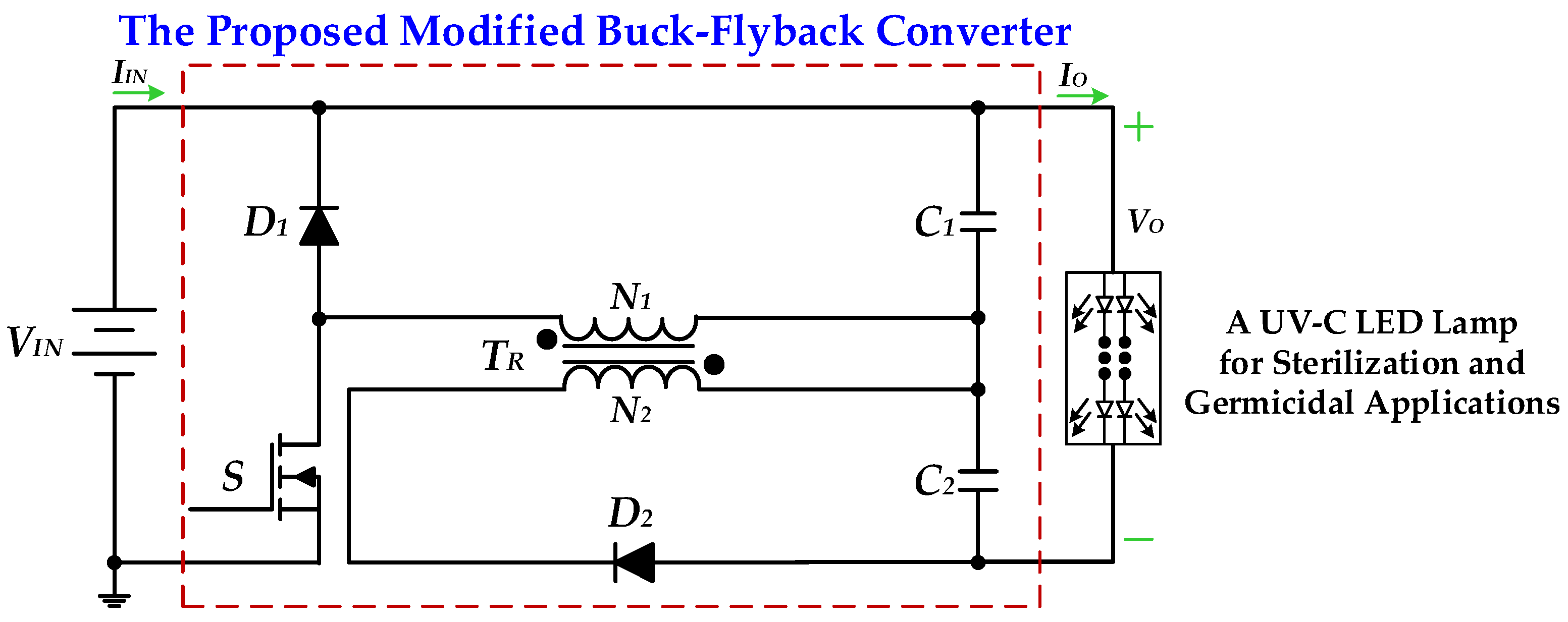
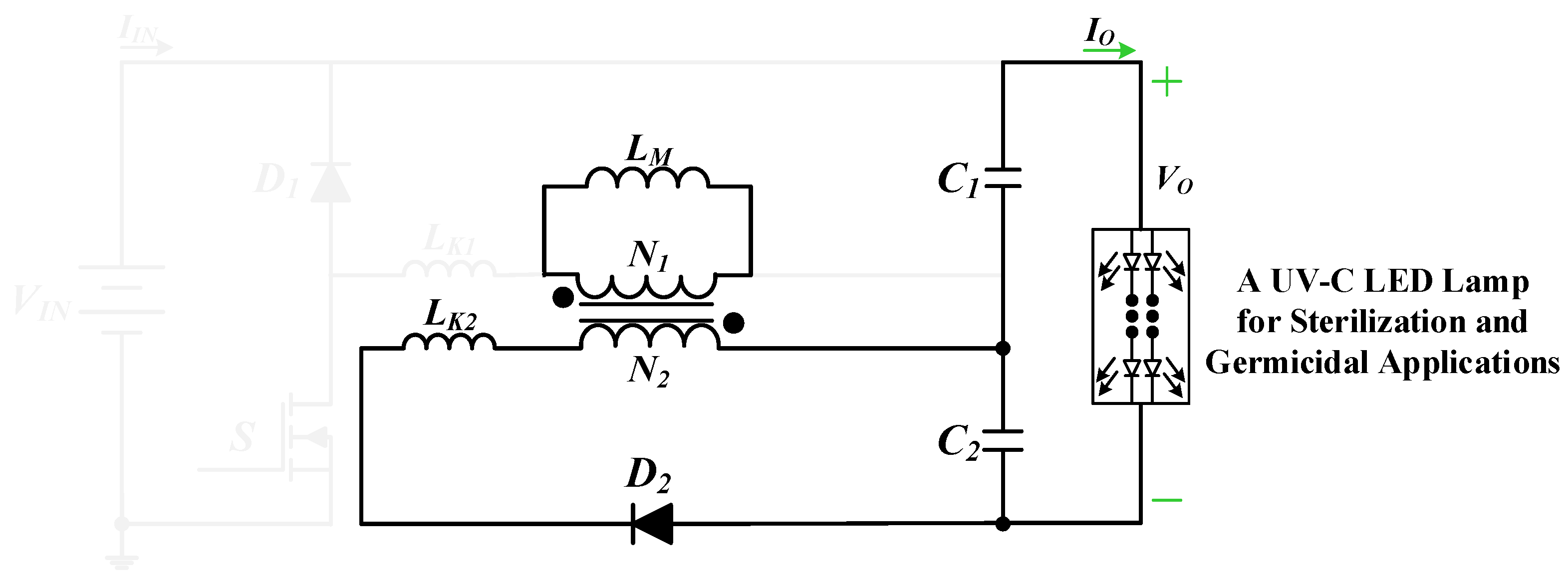
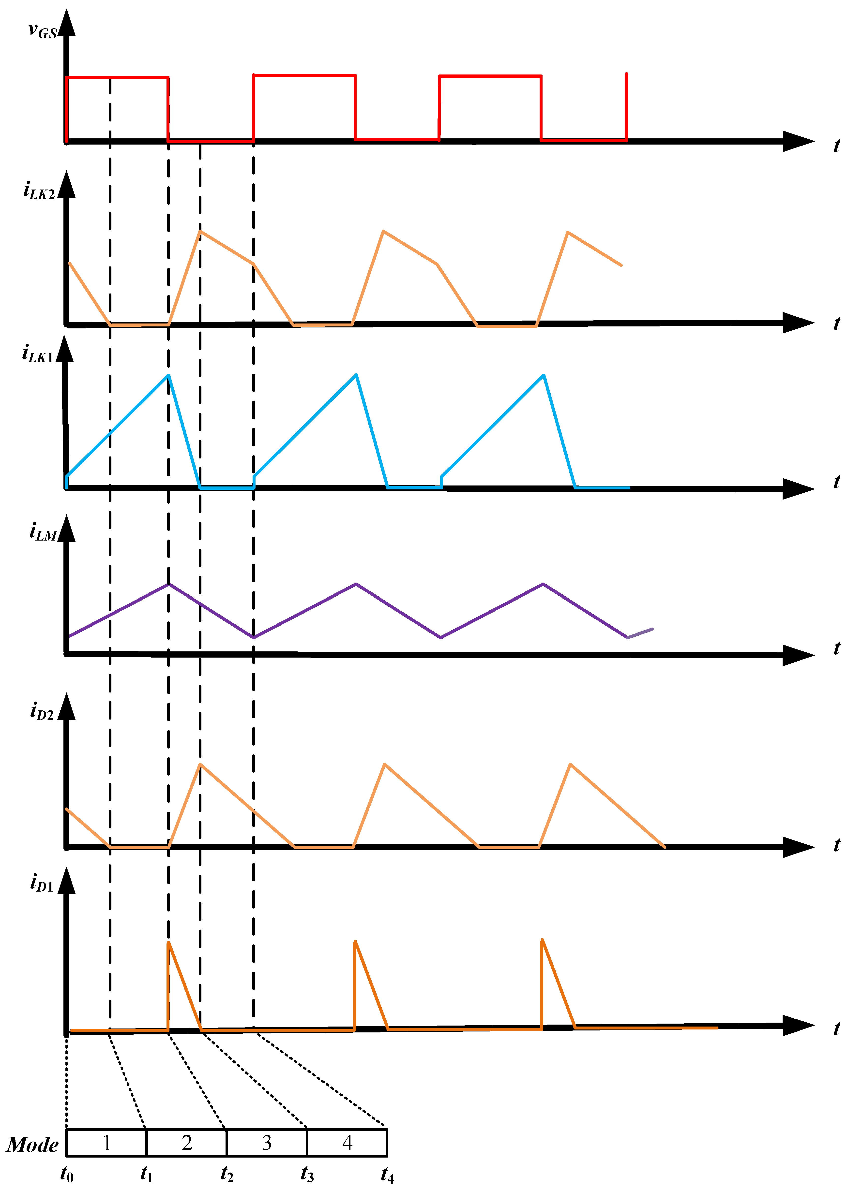
2. Descriptions and Operational Mode Analysis of the Proposed UV-C LED Lamp Driver Applied to a DC-Input Voltage for Sterilization and Germicidal Applications

Figure 1 shows the proposed UV-C LED lamp driver circuit applied to a DC-input voltage source for sterilization and germicidal applications, which is named the modified buck–flyback converter; it integrates a buck converter with a flyback converter into a single-stage DC-DC power conversion topology and includes a power switch S, two diodes (D1 and D2), a transformer TR with a primary-side turn N1 and a secondary-side turn N2, two output capacitors (C1 and C2), and a UV-C LED lamp for sterilization and germicidal applications.
Figure 2 presents the equivalent circuit of the proposed UV-C LED lamp driver, designed for use with a DC-input voltage source in sterilization and germicidal applications. This circuit model was obtained through an analysis of the operational modes of the proposed design. The following assumptions were applied to facilitate the circuit operation analysis:
(a)
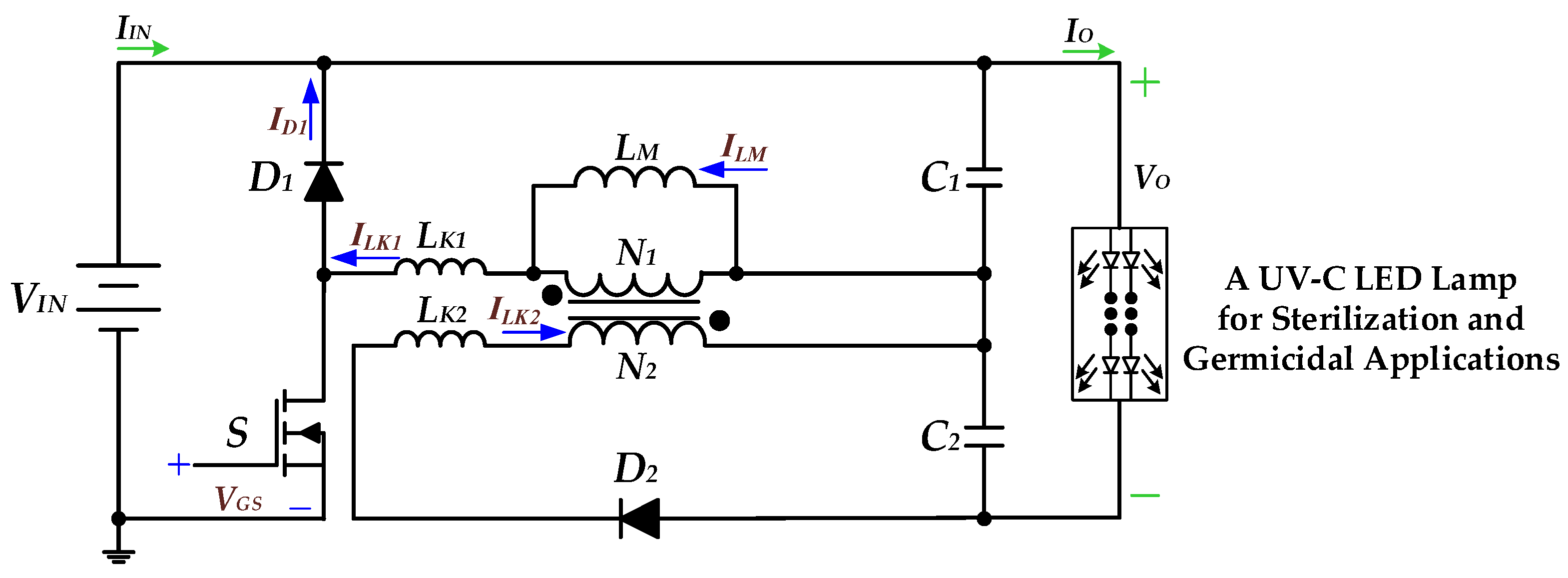
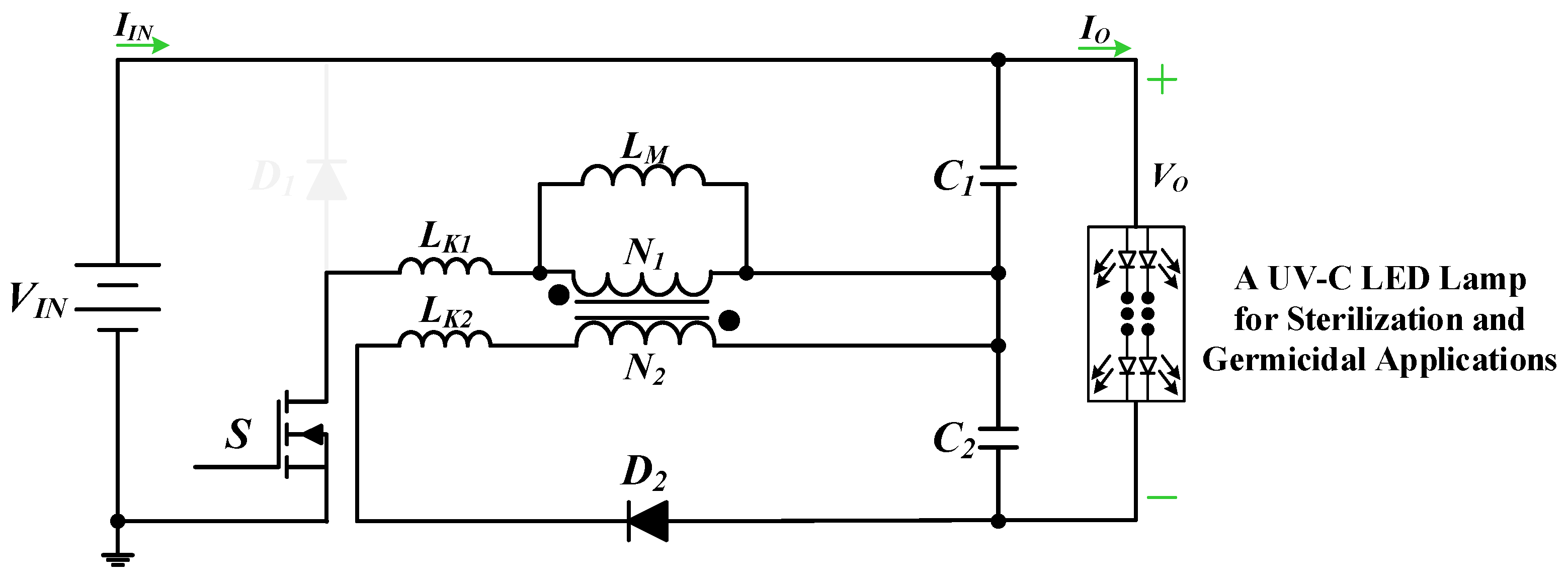
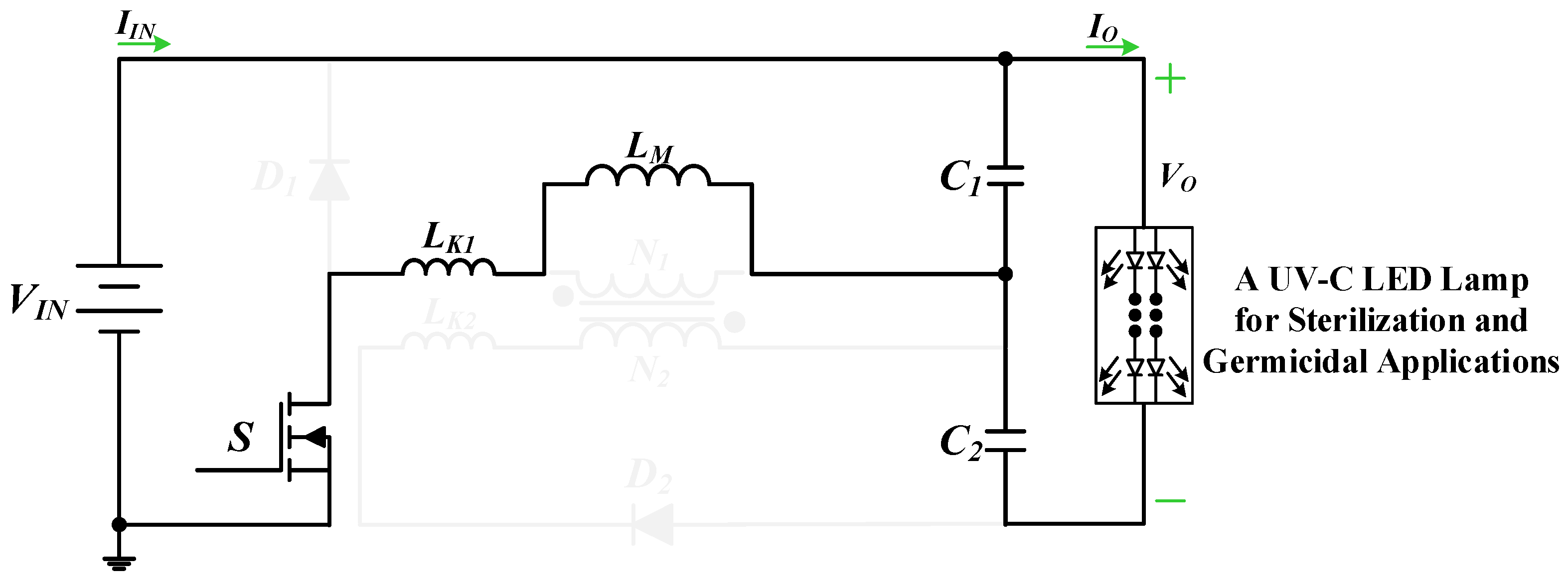
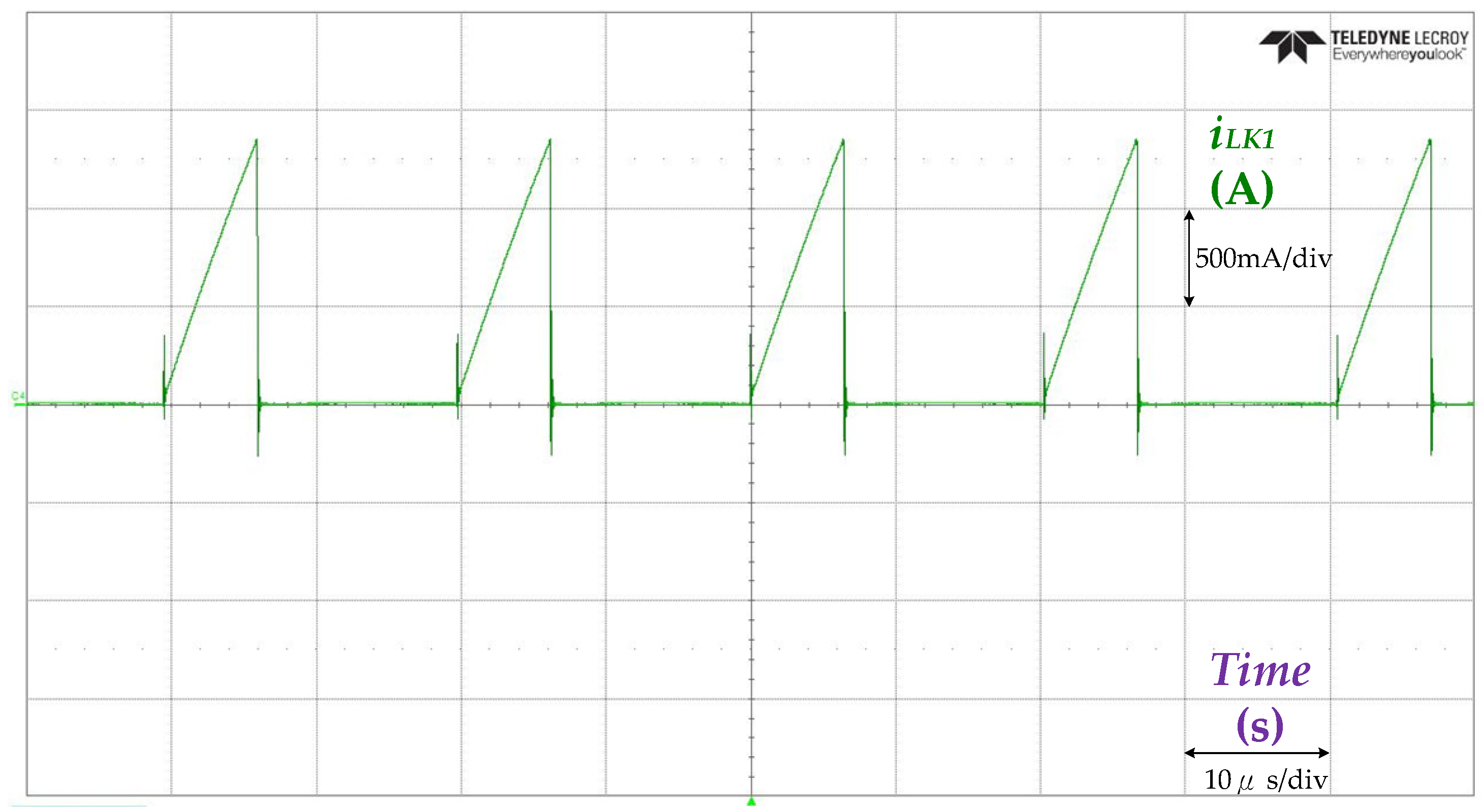
The magnetizing inductor LM of the transformer TR is designed to operate in continuous conduction mode (CCM), which means that the minimum value of the current ILM of the magnetizing inductor is above zero. Here, LK1 and LK2 represent the primary and secondary leakage inductances of the transformer TR, respectively.
(b)
The energy storage capacitors C1 and C2 are assumed to have sufficient capacity, allowing the output voltage to be treated as a constant.
(c)
All remaining circuit components are considered ideal.
Figure 3, Figure 4, Figure 5, Figure 6 and Figure 7 show the operating modes and key waveforms of the UV-C LED lamp driver applied to a DC-input voltage source for sterilization and germicidal applications, respectively, and the operational analysis is described in detail below.
Operation Mode 1 (t0t < t1): Figure 3 shows an equivalent circuit diagram for operation mode 1 of the proposed UV-C LED lamp driver applied to a DC voltage for sterilization and germicidal applications. At time t0, the power switch S is activated, causing diode D1 to be reverse-biased. The input voltage source VIN then supplies energy to the magnetizing inductor LM, the primary-side leakage inductance LK1, and the energy storage capacitor C1 through switch S. Meanwhile, diode D2 remains forward-biased, continuing its previous operation, allowing energy to transfer from the secondary-side leakage inductance LK2 to capacitor C2 via diode D2. Both capacitors C1 and C2 provide energy to the UV-C LED lamp for sterilization and germicidal applications. When the current through LK2 drops to zero at t1, mode 1 of the operation concludes.
Operational Mode 2 (t1t < t2): Figure 4 shows an equivalent circuit diagram for operation mode 2 of the proposed UV-C LED lamp driver applied to a DC voltage for sterilization and germicidal applications. At t1, the power switch S remains on, allowing the input voltage source VIN to continue supplying energy to the magnetizing inductor LM, the primary-side leakage inductance LK1, and capacitor C1 via switch S. Additionally, capacitors C1 and C2 continue to power the UV-C LED lamp for sterilization and germicidal applications. When the power switch S turns off at t2, mode 2 of the operation concludes, and the current in the magnetizing inductor iLM reaches its peak value.
Operational Mode 3 (t2t < t3): Figure 5 shows an equivalent circuit diagram for operation mode 3 of the proposed UV-C LED lamp driver applied to a DC voltage for sterilization and germicidal applications. At t2, once the power switch S is turned off, diode D1 becomes forward-biased, allowing the magnetizing inductor LM and the primary-side leakage inductance LK1 to transfer energy to capacitor C1 through diode D1. Simultaneously, the secondary-side leakage inductance LK2 supplies energy to capacitor C2 via diode D2. Both capacitors C1 and C2 continue to power the UV-C LED lamp for sterilization and germicidal applications. When the current in the primary-side leakage inductance iLK1 reaches zero at t3, mode 3 of the operation concludes.
Operational Mode 4 (t3t < t4): Figure 6 shows an equivalent circuit diagram for operation mode 4 of the proposed UV-C LED lamp driver applied to a DC voltage for sterilization and germicidal applications. At t3, with the power switch S still off, the magnetizing inductor LM and the secondary-side leakage inductance LK2 supply energy to capacitor C2 through diode D2. Additionally, capacitors C1 and C2 continue to power the UV-C LED lamp for sterilization and germicidal applications. When the power switch S turns on again at t4, mode 4 concludes, and the magnetizing inductor current iLM reaches its minimum value. At this point, the circuit returns to operation mode 1.

3. Design Considerations of Key Parameters in the Proposed UV-C LED Lamp Driver Circuit Applied to a DC-Input Voltage for Sterilization and Germicidal Applications

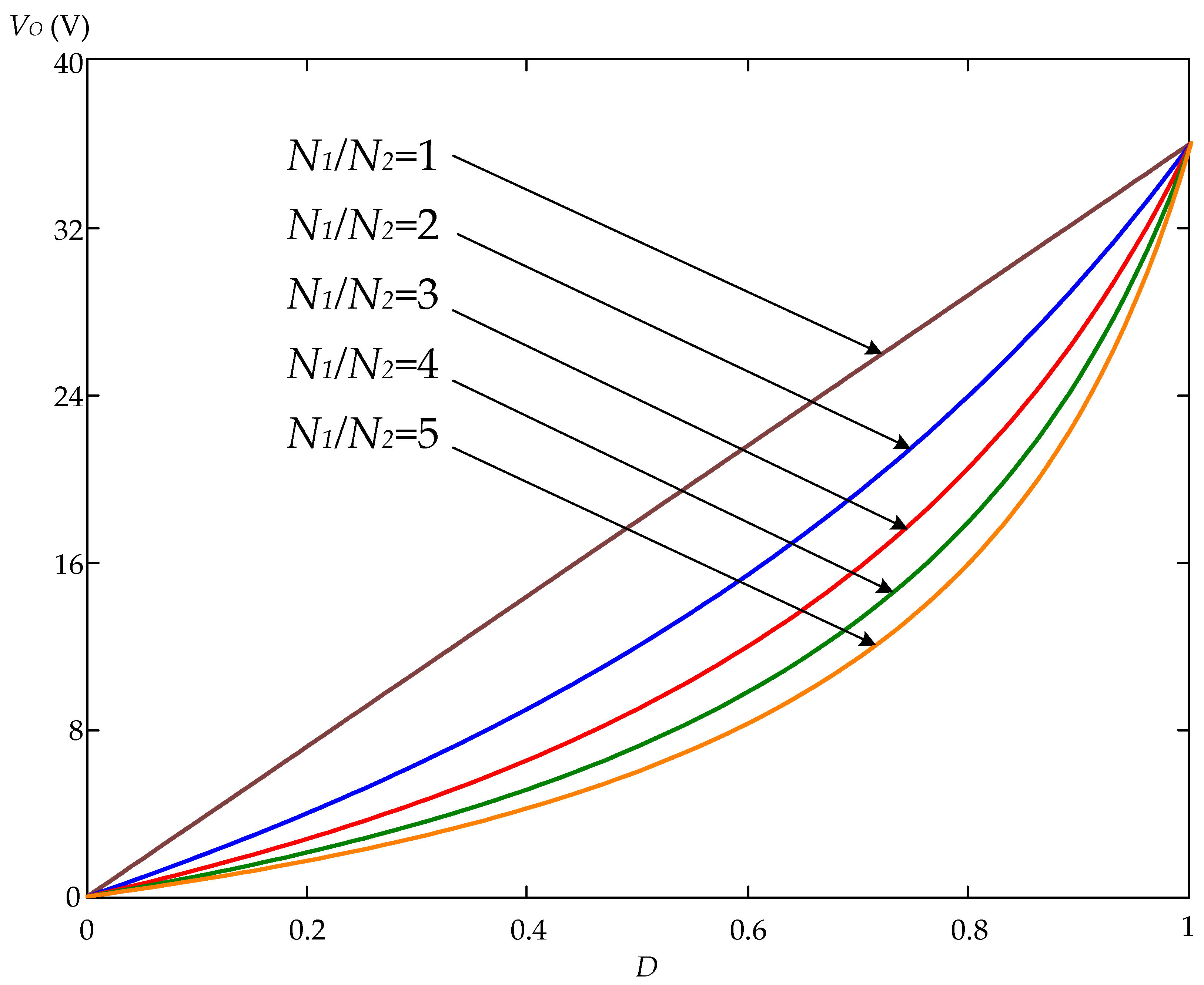
3.1. Design Consideration of the Duty Cycle D

Using the volt–second balance theorem, the voltage across the magnetizing inductor LM during the switch’s on-time, multiplied by the duration of the on-time, is equal to the voltage across LM during the switch’s off-time, multiplied by the duration of the off-time. This relationship can be expressed by the following equation:
V I N V O U T 2 D T S = N 1 N 2 V O U T 2 1 D T S
where D is the duty cycle of the power switch and TS is the switching period. The output voltage VOUT is related to the input voltage VIN, and the duty cycle D as well as the turns ratio of N1/N2, and can be expressed as
V O U T = 2 D V I N D + ( 1 D ) N 1 N 2
In accordance with Equation (2), Figure 8 demonstrates the correlation between the output voltage VO and the duty cycle D for various turns ratios N1/N2. Substituting the circuit parameters into Equation (2), with a VIN of 18 V, a VOUT of 10 V, an N1 of 1, and an N2 of 1, a value of 0.278 can be obtained for the duty cycle D. In addition, when implementing the prototype of the UV-C LED lamp driver circuit, the duty cycle D is given a value of 0.3.

3.2. Design Consideration of the Magnetizing Inductor LM

The peak-to-peak value of the magnetizing inductor LM, which is denoted as ΔILM, can be given by
Δ I L M = V I N V O U T 2 D T S L M = V O U T N P 1 D T S 2 L M N S
The average value of the magnetizing inductor current ILMB for the boundary cases of continuous conduction mode and discontinuous conduction mode can be expressed as
I L M B = I O B = Δ I L M 2
Combining Equation (3) with Equation (4), the magnetizing inductor in the boundary conduction mode, which is denoted as LMB, can be expressed by the following equation:
L M B = V O U T N P 1 D 2 2 I O B N S f S
As stated by Equation (5), Figure 9 shows the relationship between the magnetizing inductor in the boundary conduction mode LMB and the switching frequency fS at different duty cycles D.
Assuming the average output current IOB at the boundary condition is 1.3 times the average output current IO, the magnetizing inductance value for boundary conduction mode LMB can be calculated using Equation (5). This calculation is based on the following conditions of a VOUT of 10 V, an NP of 1, an NS of 1, an IOB of 0.429 A, and an fS of 50 kHz.
L M B = V O U T N P 1 D 2 2 I O B N S f S = 10 1 1 0.278 2 2 0.429 1 50000 = 84.1   μ H
In order for the magnetizing inductor current to operate in continuous conduction mode, the magnetizing inductor LM needs to be larger than the LMB in boundary conduction mode and is set to 85 μH when the circuit is implemented.

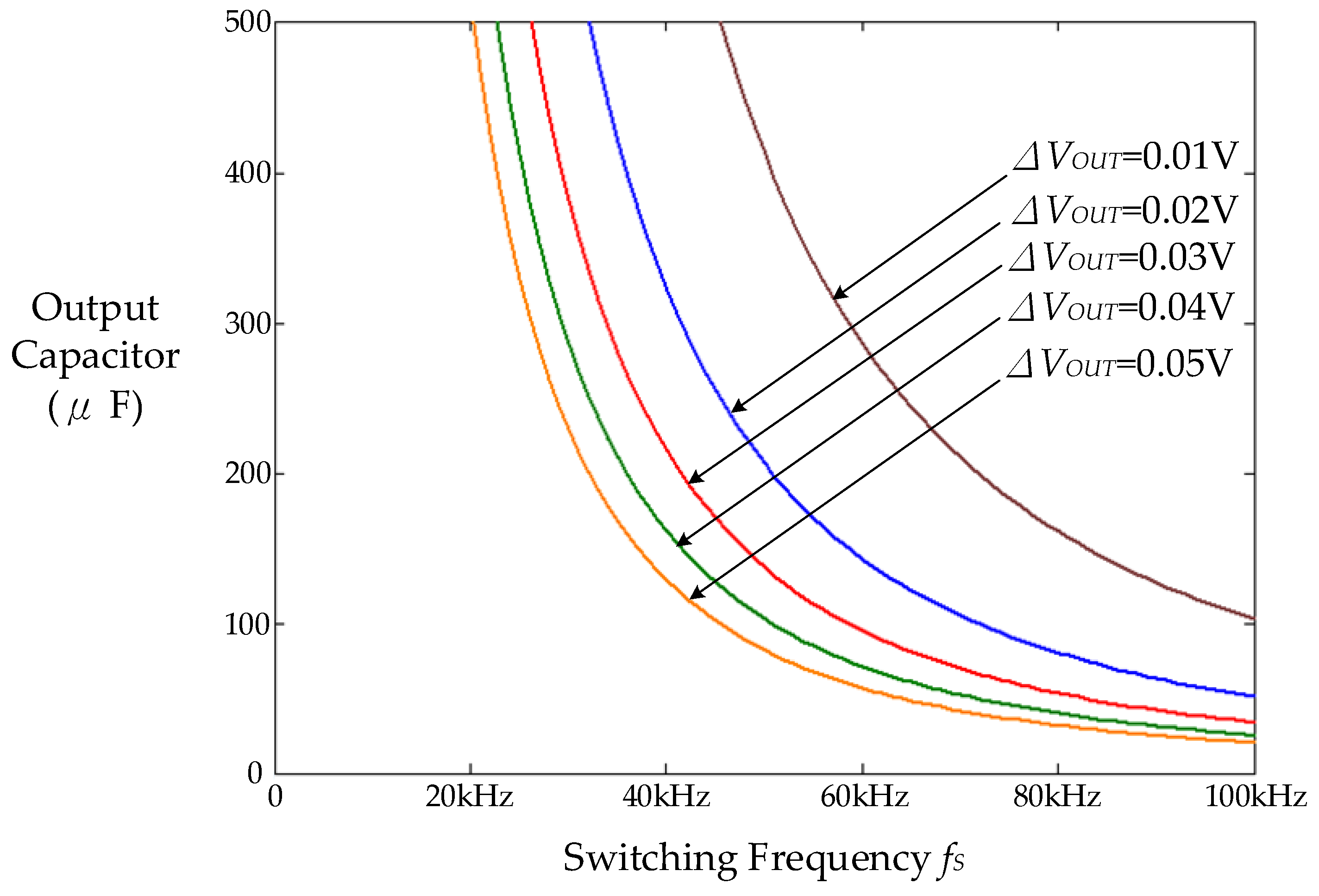
3.3. Design Consideration of the Output Capacitors CO1 and CO2

The amount of charge variation ΔQ stored in the output capacitor is related to the amount of voltage variation ΔV at both ends of the capacitor and the capacitance value C. Thus, the peak-to-peak value of the output voltage ripple of the output capacitor, which is denoted as ΔVOUT, can be expressed by the following equation.
Δ V O U T = Δ Q C O 1 2 = 2 C O 1 1 2 Δ I L M 2 T S 2 = Δ I L M T S 4 C O 1
By inserting Equation (3) into Equation (6), the output voltage ripple ΔVOUT is given by
Δ V O U T = V O U T N P ( 1 D ) T S 2 8 L M C O N S
The percentage of the output voltage ripple ΔVOUT/VOUT can be expressed as
Δ V O U T V O U T = N P ( 1 D ) T S 2 8 L M C O N S 100 %
After sorting out Equation (8), the design formula of output capacitors CO1 and CO2 can be obtained as follows:
C O 1 = C O 2 = N P ( 1 D ) V O U T 8 L M N S f S 2 Δ V O U T
As stated by Equation (9), Figure 10 displays the relationship between the output capacitor and the switching frequency fS under different output voltage ripples ΔVOUT.
Substituting the circuit parameters into Equation (9) with a VOUT of 10 V, an NP of 1, an NS of 1, an fS of 50 kHz, an LM of 85 μH, and a ΔVOUT of 0.02 V, the values of capacitors CO1 and CO2 are found as follows:
C O 1 = C O 2 = N P ( 1 D ) V O U T 8 L M N S f S 2 Δ V O U T = 1 1 0.3 10 8 85 10 6 1 50000 2 0.02 = 205.9   μ F
In addition, the output capacitors CO1 and CO2 are set to 220 μF for the purpose of decreasing the ripple of the output voltage when implementing the circuit.

4. Experimental Results of Prototype UV-C LED Lamp Driver Circuit Applied to DC-Input Voltage Source for Sterilization and Germicidal Applications

Figure 11 presents a photograph of the UV-C LED module for sterilization and germicidal applications used in the experiment. Table 1 presents the specifications of the UV-C LED module for sterilization and germicidal applications used in the experiment, and its information is as follows: the rated power is 0.33 W, the rated voltage is 10 V, the rated current is 33 mA, the wavelength is 275 nm, and the viewing angle is 120 degrees. Additionally, the “viewing angle”, which is also called the “azimuth angle”, is the luminous range of the LED light source, and the unit is “degree”. When the package of the LED light source is tilted to observe the change in the light output, the angle from the peak output value to the characteristic value of the angle that can be recognized, and the angle of half of the brightness of the peak output value, are multiplied by 2 (front side as the basis for left–right symmetry), which is known as the viewing angle.
Figure 12 displays a photograph of the UV-C LED lamp for sterilization and germicidal applications used in the experiment. Referring to Figure 10, ten UV-C LED modules were connected in parallel to establish the UV-C LED lamp for sterilization and germicidal applications used in the experiment in this paper, and their information is shown in Table 2; they had a rated output power PO of 3.3 W, a rated output voltage VO of 10 V, and a rated output current IO of 330 mA. A prototype UV-C LED lamp driver circuit applied to a DC-input voltage of 18 V was successfully implemented and tested for sterilization and germicidal applications. Table 3 shows the key components used in the proposed UV-C LED lamp driver circuit for sterilization and germicidal applications applied to a DC-input voltage source.
Figure 13 presents experimental waveforms of the input voltage VIN and input current IIN; their measured mean values are 18 V and 0.205 A, respectively. Figure 14 and Figure 15 are experimental waveforms of leakage inductor currents iLK1 and iLK2, respectively. The experimental waveforms of switch voltage VDS and switch current IDS are shown in Figure 16. Figure 17 presents the experimental waveforms of output voltage VOUT and output current IOUT; their measured mean values are approximately 10.2 V and 0.4 A, respectively. In addition, the measured input power and output power are 3.69 W and 3.366 W, respectively. Moreover, the circuit efficiency of the proposed UV-C LED lamp driver is 91.22%.
Figure 18 presents a photograph of supplying the experimental UV-C LED lamp for sterilization and germicidal applications with a prototype driver circuit applied to a DC-input voltage source of 18 V.

5. Discussion

A comparative study (including wavelength, optical power, viewing angle, and operating current) of the utilized UV-C LED sterilization and germicidal module in ref. [26] in comparison with the one utilized in this paper is presented. Table 4 illustrates a comparison between the UV-C LED sterilization and germicidal module in [26] and the module utilized in this paper. As can be seen from Table 4, the UV-C LED sterilization and germicidal module utilized in this paper has similar wavelength, viewing angle, and operating current compared with the module in [26]. In addition, the UV-C LED sterilization and germicidal module used in [26] has higher optical power.
In this investigation, the proposed driver circuit is studied in comparison with the driver circuit in the reference literature [26] (including circuit structure, DC-input voltage, output power (output voltage/current), measured circuit efficiency, and number of circuit components required). Table 5 compares the existing DC-DC LED driver from [26], a Ćuk converter that delivers 7.5 W of rated power (75 V/0.1 A) from a 48 V DC input, with the proposed design, a modified buck–flyback converter that provides 3.3 W of rated power (10 V/0.33 A) from an 18 V DC input. As can be seen from Table 5, the proposed DC-DC LED driver circuit has one more diode and saves one capacitor and one magnetic component compared to the driver circuit in [26]. In addition, the measured efficiency of the proposed DC-DC LED driver circuit is 91.22%, which is slightly lower than the measured efficiency of 91.69% of the existing driver circuit in [26].
The proposed DC-DC power supply can provide UV-C LED lamps on a DC-input voltage source for sterilization and disinfection applications. The novelty and advantages of the proposed DC-DC power supply are compared with those of the existing power supply in [27] (including the circuit structure, DC-input voltage, output power (output voltage/current), measured circuit efficiency, and number of circuit components required). A comparison between the existing DC-DC LED driver of [27], which is a modified buck converter utilizing coupled inductors to deliver 8 W of rated power (8 V/1 A) from a 12 V DC input, and the proposed DC-DC LED driver of [27], which is a modified buck–flyback converter that delivers 3.3 W of rated power (10 V/0.33 A) from an 18 V DC input, is shown in Table 6. From Table 6, it can be seen that the proposed DC-DC LED driver circuit saves one diode compared to the circuit in [27]. Additionally, the measured efficiency of the proposed DC-DC LED driver circuit is 91.22%, which is slightly higher than the measured efficiency of 91% of the existing driver circuit in [27].
In addition, ref. [29] developed a driver circuit which consists of a buck converter combined with a flyback converter to provide 72 W (36 V/2 A) of output power to an LED streetlight module at a DC-input voltage of 48 V. In this paper, we propose a driver circuit which consists of a modified buck converter and a flyback converter to provide a 3.3 W power rating (10 V/330 mA) to a UV-C LED sterilization and germicidal lamp at a DC-input voltage of 18 V. The design concept of this paper is similar to that of ref. [29] and the difference between the two manuscripts lies in the location of the two output capacitors. In ref. [29], the positive polarity of the upper output capacitor located on the secondary side of the transformer is connected to the anode of the experimental LED load, and the negative polarity of the lower output capacitor located on the primary side of the transformer is connected to the cathode of the experimental LED load. In addition, in this paper, the positive polarity of the upper output capacitor located on the primary side of the transformer is connected to the anode of the experimental LED load, and the negative polarity of the lower output capacitor located on the secondary side of the transformer is connected to the cathode of the experimental LED load.

6. Conclusions

This paper presents and implements an innovative electronic driver designed to power a UV-C LED disinfection and sterilization lamp. The lamp comprises ten UV-C LED modules connected in parallel, powered by a unique single-stage, single-switch power conversion circuit that combines a modified buck converter with a flyback converter. Additionally, this driver recycles energy stored in the transformer’s leakage inductance, enhancing circuit efficiency. A prototype driver circuit was developed and tested, achieving a DC-input voltage of 18 V, rated at 3.3 W of power, a 10 V output, and a 330 mA current. The experimental results show efficiency above 91%, confirming the driver’s effectiveness for UV-C LED disinfection and sterilization applications.

Author Contributions

C.-A.C. developed the circuit topology of the lamp driver and designed the methodology; C.-H.C., H.-L.C. and E.-C.C. arranged the software resources, set up the simulation, and performed the circuit simulations for the proposed lamp driver; W.-Y.Y. and L.-F.L. implemented the prototype circuit of the proposed lamp driver, and carried out the measurements of the lamp driver circuit as well as analyzing the experimental results with guidance from C.-A.C.; C.-A.C. prepared the first draft of the article and revised the manuscript for submission. All authors have read and agreed to the published version of the manuscript.

Funding

This research was funded by the National Science and Technology Council (NSTC) of Taiwan for its grant numbers NSTC 112-2813-C-214-039-E, NSTC 112-2221-E-214-005, and NSTC 113-2221-E-214-020.

Institutional Review Board Statement

Not applicable.

Informed Consent Statement

Not applicable.

Data Availability Statement

The data presented in this study are available in the article.

Acknowledgments

The authors would like to convey their sincerest gratitude to National Science and Technology Council of Taiwan for supporting this study (grant numbers NSTC 112-2813-C-214-039-E, NSTC 112-2221-E-214-005, and NSTC 113-2221-E-214-020).

Conflicts of Interest

The authors declare no conflicts of interest.

References

  1. Kebbi, Y.; Muhammad, A.I.; Sant’Ana, A.S.; Prado-Silva, L.D.; Liu, D.; Ding, T. Recent advances on the application of UV-LED technology for microbial inactivation: Progress and mechanism. Compr. Rev. Food Sci. Food Saf. 2020, 19, 3501–3527. [Google Scholar] [CrossRef] [PubMed]
  2. Beck, S.E.; Ryu, H.; Boczek, L.A.; Cashdollar, J.L.; Jeanis, K.M.; Rosenblum, J.S.; Lawal, O.R.; Linden, K.G. Evaluating UV-C LED disinfection performance and investigating potential dual-wavelength synergy. Water Res. 2017, 109, 207–216. [Google Scholar] [CrossRef]
  3. Linden, K.G.; Hull, N.; Speight, V. Thinking outside the treatment plant: UV for water distribution system disinfection. Acc. Chem. Res. 2019, 52, 1226–1233. [Google Scholar] [CrossRef] [PubMed]
  4. Koutchm, T.; Popović, V.; Green, A. Chapter 1—Overview of Ultraviolet (UV) LEDs Technology for Applications in Food Production. In Ultraviolet LED Technology for Food Applications; Academic Press: New York, NY, USA, 2019; pp. 1–23. [Google Scholar]
  5. Song, K.; Mohseni, M.; Taghipour, F. Application of ultraviolet light-emitting diodes (UV-LEDs) for water disinfection: A review. Water Res. 2016, 94, 341–349. [Google Scholar] [CrossRef]
  6. Kim, D.; Kang, D. UVC LED Irradiation Effectively Inactivates Aerosolized Viruses, Bacteria, and Fungi in a Chamber-Type Air Disinfection System. Appl. Environ. Microbiol. 2018, 84, e00944-18. [Google Scholar] [CrossRef] [PubMed]
  7. Akgün, M.P.; Ünlütürk, S. Effects of ultraviolet light emitting diodes (LEDs) on microbial and enzyme inactivation of apple juice. Int. J. Food Microbiol. 2017, 260, 65–74. [Google Scholar] [CrossRef] [PubMed]
  8. Kaya, Z.; Yıldız, S.; Ünlütürk, S. Effect of UV-C irradiation and heat treatment on the shelf life stability of a lemon–melon juice blend: Multivariate statistical approach. Innov. Food Sci. Emerg. Technol. 2015, 29, 230–239. [Google Scholar] [CrossRef]
  9. Guan, Z.; Liu, P.; Zhou, T.; Zhou, L.; Zhang, D.; Xie, Q.; Yu, Q.; He, Y.; Wang, S.; Wang, X.; et al. Study on the Light Field Regulation of UVC-LED Disinfection for Cold Chain Transportation. Appl. Sci. 2022, 12, 1285. [Google Scholar] [CrossRef]
  10. Storm, N.; McKay, L.G.A.; Downs, S.N.; Johnson, R.I.; Birru, D.; de Samber, M.; Willaert, W.; Cennini, G.; Griffiths, A. Rapid and complete inactivation of SARS-CoV-2 by ultraviolet-C irradiation. Sci. Rep. 2020, 10, 22421. [Google Scholar] [CrossRef] [PubMed]
  11. McDevitt, J.J.; Rudnick, S.N.; Radonovich, L.J. Aerosol susceptibility of influenza virus to UV-C light. Appl. Environ. Microbiol. 2012, 78, 1666–1669. [Google Scholar] [CrossRef]
  12. Atari, N.; Mamane, H.; Silberbush, A.; Zuckerman, N.; Mandelboim, M.; Gerchman, Y. Disinfection of SARS-CoV-2 by UV-LED 267 nm: Comparing different variants. Sci. Rep. 2023, 13, 8229. [Google Scholar] [CrossRef] [PubMed]
  13. Ma, B.; Gundy, P.M.; Gerba, C.P.; Sobsey, M.D.; Linden, K.G. UV inactivation of SARS-CoV-2 across the UVC spectrum: KrCl excimer, mercury-vapor, and light-emitting-diode (LED) sources. Appl. Environ. Microbiol. 2021, 87, e01532-21. [Google Scholar] [CrossRef]
  14. Beck, S.E.; Rodriguez, R.A.; Hawkins, M.A.; Hargy, T.M.; Larason, T.C.; Linden, K.G. Comparison of UV-induced inactivation and RNA damage in MS2 phage across the germicidal UV spectrum. Appl. Environ. Microbiol. 2015, 82, 1468–1474. [Google Scholar] [CrossRef]
  15. Biasin, M.; Bianco, A.; Pareschi, G.; Cavalleri, A.; Cavatorta, C.; Fenizia, C.; Galli, P.; Lessio, L.; Lualdi, M.; Tombetti, E.; et al. Clerici. UV-C irradiation is highly effective in inactivating SARS-CoV-2 replication. Sci. Rep. 2021, 11, 6260–6267. [Google Scholar] [CrossRef] [PubMed]
  16. Matthew, U.O.; Nwanakwaugwu, A.C.; Kazaure, J.S.; Nwamouh, U.C.; Haruna, K.; Okafor, N.U.; Olawoyin, O.O. Ultra Violet (UV) Light Irradiation Device for Hospital Disinfection. Int. J. Inf. Commun. Technol. Hum. Dev. 2022, 14, 1–24. [Google Scholar] [CrossRef]
  17. Schmitz, C.; Poplata, T.; Feilen, A.; Strehmel, B. Radiation crosslinking of pigmented coating material by UV LEDs enabling depth curing and preventing oxygen inhibition. Prog. Org. Coat. 2020, 144, 105663. [Google Scholar] [CrossRef]
  18. Shatalov, M.; Jain, R.; Saxena, T.; Dobrinsky, A.; Shur, M. Chapter Two—Development of Deep UV LEDs and Current Problems in Material and Device Technology. Semicond. Semimet. 2017, 96, 45–83. [Google Scholar]
  19. Liang, J.J.; Liao, C.C.; Chang, C.S.; Lee, C.Y.; Chen, S.Y.; Huang, S.B.; Yeh, Y.F.; Singh, K.J.; Kuo, H.C.; Lin, Y.L.; et al. The Effectiveness of Far-Ultraviolet (UVC) Light Prototype Devices with Different Wavelengths on Disinfecting SARS-CoV-2. Appl. Sci. 2021, 11, 10661. [Google Scholar] [CrossRef]
  20. Moreno-Araujo, J.E.; Ruíz-Valdiviezo, V.M.; Camas-Anzueto, J.L.; Pérez-Patricio, M.; Hernández-Gutiérrez, C.A. Design strategies based on UV-C LED characterization to enhance Escherichia coli inactivation. J. Water Process Eng. 2024, 62, 105423. [Google Scholar] [CrossRef]
  21. Ueki, H.; Ito, M.; Furusawa, Y.; Yamayoshi, S.; Inoue, S.; Kawaoka, Y. A 265-Nanometer High-Power Deep-UV Light-Emitting Diode Rapidly Inactivates SARS-CoV-2 Aerosols. ASM J. 2022, 7, 1–7. [Google Scholar] [CrossRef]
  22. Kim, S.-J.; Kim, D.-K.; Kang, D.-H. Using UVC light-emitting diodes at wavelengths of 266 to 279 nanometers to inactivate foodborne pathogens and pasteurize sliced cheese. Appl. Environ. Microbiol. 2016, 82, 11–17. [Google Scholar] [CrossRef] [PubMed]
  23. Cheng, C.A.; Lan, L.F.; Hou, S.H.; Lin, C.K. A Single-Stage Electronic Lighting Driver for a Deep Ultraviolet LED Disinfection and Sterilization Lamp. In Proceedings of the The Workshop on Wide Bandgap Power Devices and Applications in Asia (WiPDA-Asia 2023), Hsinchu, Taiwan, 27–29 August 2023; pp. 1–3. [Google Scholar]
  24. Mathebula, T.; Leuschner, F.W.; Chowdhury, S.P. The Use of UVC-LEDs for the Disinfection of Mycobacterium Tuberculosis. In Proceedings of the 2018 IEEE PES/IAS PowerAfrica, Cape Town, South Africa, 28–29 June 2018; pp. 739–744. [Google Scholar]
  25. ICNIRP Statement Light-Emitting Diodes (LEDS): Implications for Safety. Available online: https://www.icnirp.org/cms/upload/publications/ICNIRPled2020.pdf (accessed on 10 November 2024).
  26. Juarez-Leon, F.A.; Soriano-Sánchez, A.G.; Rodríguez-Licea, M.A.; Perez-Pinal, F.J. Design and Implementation of a Germicidal UVC-LED Lamp. IEEE Access 2020, 8, 196951–196962. [Google Scholar] [CrossRef] [PubMed]
  27. Pouladi, F.; Farzanehfard, H.; Adib, E.; Le Sage, H. Single-Switch Soft-Switching LED Driver Suitable for Battery-Operated Systems. IEEE Trans. Ind. Electron. 2019, 66, 2726–2734. [Google Scholar] [CrossRef]
  28. Cheng, C.-A.; Chang, C.-H.; Chang, E.-C.; Cheng, H.-L.; Yan, W.-Y.; Lan, L.-F. A Novel Electronic Lighting Driver for a UV-C LED Disinfection and Sterilization Lamp Applied to a DC-Input Voltage Source. In Proceedings of the IEEE International Conference on Consumer Electronics (IEEE ICCE-TW 2024), Taichung, Taiwan, 9–11 July 2024. [Google Scholar]
  29. Cheng, C.-A.; Chang, C.-H.; Cheng, H.-L.; Chang, E.-C.; Lin, Y.-R.; Lan, L.-F. A Novel Light-Emitting Diode Streetlight Driver Circuit Applied to a Direct Current-Input Voltage Source. Sustainability 2023, 15, 10934. [Google Scholar] [CrossRef]
Figure 1. The proposed UV-C LED lamp driver circuit applied to a DC-input voltage source for sterilization and germicidal applications.
Applsci 15 01498 g001
Figure 2. The equivalent circuit of the proposed UV-C LED lamp driver applied to a DC-input voltage source for sterilization and germicidal applications.
Applsci 15 01498 g002
Figure 3. The equivalent circuit for operation mode 1 of the proposed UV-C LED lamp driver circuit applied to a DC-input voltage source for sterilization and germicidal applications.
Applsci 15 01498 g003
Figure 4. The equivalent circuit for operation mode 2 of the proposed UV-C LED lamp driver circuit applied to a DC-input voltage source for sterilization and germicidal applications.
Applsci 15 01498 g004
Figure 5. The equivalent circuit for operation mode 3 of the proposed UV-C LED lamp driver circuit applied to a DC-input voltage source for sterilization and germicidal applications.
Applsci 15 01498 g005
Figure 6. The equivalent circuit for operation mode 4 of the proposed UV-C LED lamp driver circuit applied to a DC-input voltage source for sterilization and germicidal applications.
Applsci 15 01498 g006
Figure 7. Key waveforms of the proposed UV-C LED lamp driver circuit applied to a DC-input voltage source for sterilization and germicidal applications.
Applsci 15 01498 g007
Figure 8. The output voltage VO versus the duty cycle D for various turns ratios N1/N2.
Applsci 15 01498 g008
Figure 9. Magnetizing inductor in boundary conduction mode LMB versus the switching frequency fS under different duty cycles D.
Applsci 15 01498 g009
Figure 10. Output capacitor versus switching frequency fS under different output voltage ripples ΔVOUT.
Applsci 15 01498 g010
Figure 11. A photograph of the UV-C LED module for sterilization and germicidal applications used in the experiment.
Applsci 15 01498 g011
Figure 12. A photograph of the UV-C LED lamp for sterilization and germicidal applications used in the experiment.
Applsci 15 01498 g012
Figure 13. Experimental waveforms of input voltage VIN (10 V/div) and input current IIN (1 A/div); time scale: 10 μs/div.
Applsci 15 01498 g013
Figure 14. Experimental waveform of leakage inductor current iLK1 (500 mA/div); time scale: 10 μs/div.
Applsci 15 01498 g014
Figure 15. Experimental waveform of leakage inductor current iLK2 (500 mA/div); time scale: 10 μs/div.
Applsci 15 01498 g015
Figure 16. Experimental waveforms of switch voltage VDS (20 V/div) and current IDS (2 A/div); time scale: 10 μs/div.
Applsci 15 01498 g016
Figure 17. Experimental waveforms of output voltage VO (5 V/div) and output current IO (200 mA/div); time scale: 10 μs/div.
Applsci 15 01498 g017
Figure 18. A photograph of supplying the experimental UV-C LED lamp for sterilization and germicidal applications with a prototype driver circuit applied to a DC-input voltage source of 18 V.
Applsci 15 01498 g018
Table 1. Specifications of the UV-C LED module for sterilization and germicidal applications.
ParameterValue
Rated Power0.33 W
Rated Voltage10 V
Rated Current33 mA
Wavelength275 nm
Viewing Angle120 degrees
Table 2. The specifications of the experimental UV-C LED lamp for sterilization and germicidal applications.
ParameterValue
Output Power PO3.3 W
Output Voltage VO10 V
Output Current IO330 mA
Table 3. Key components used in the proposed UV-C LED lamp applied to a DC-input voltage source for sterilization and germicidal applications.
ComponentValue
Power Switch SIRF840
Magnetizing Inductor LM85 μH
Turns Ratio of Transformer N1:N2 = 1:1
Leakage Inductors LK1 and LK21 μH
Diodes D1 and D2MUR840
Capacitors C1 and C2220 μF
Table 4. A comparison between the UV-C LED sterilization and germicidal module in [26] and the one utilized in this paper.
ItemThe UV-C LED Sterilization and Germicidal Module in [26]The UV-C LED Sterilization and Germicidal Module Utilized in This Paper
Typical Wavelength280 nm275 nm
Typical Optical Power 40 mW4 mW
Viewing Angle130 degree120 degree
Operating Current350 mA330 mA
Table 5. A comparison between the existing DC-DC LED driver in [26] and the proposed one.
ItemExisting DC-DC LED Driver in Ref. [26]Proposed
DC-DC LED Driver
Circuit StructureĆuk converterModified buck–flyback converter
DC-Input Voltage48 V18 V
Output Power (Output Voltage/Current)7.5 W (75 V/0.1 A)3.3 W (10 V/0.33 A)
Number of Power Switches Needed11
Number of Capacitors Needed32
Number of Magnetic Elements Needed21
Number of Diodes Needed12
Measured Circuit Efficiency91.69%91.22%
Table 6. A comparison between the existing DC-DC LED driver in [27] and the proposed one.
ItemExisting DC-DC LED Driver in Ref. [27]Proposed
DC-DC LED Driver
Circuit StructureModified buck converter with a coupled inductorsModified buck–flyback converter
DC-Input Voltage12 V18 V
Output Power (Output Voltage/Current)8 W (8 V/1 A)3.3 W (10 V/0.33 A)
Number of Power Switches Needed11
Number of Capacitors Needed22
Number of Magnetic Elements Needed11
Number of Diodes Needed32
Measured Circuit Efficiency91%91.22%
Disclaimer/Publisher’s Note: The statements, opinions and data contained in all publications are solely those of the individual author(s) and contributor(s) and not of MDPI and/or the editor(s). MDPI and/or the editor(s) disclaim responsibility for any injury to people or property resulting from any ideas, methods, instructions or products referred to in the content.

