Communication

The Strain Heterogeneity and Microstructural Shear Bands in AZ31B Magnesium Alloy

1
School of Civil & Architecture Engineering, Xi’an Technological University, Xi’an 710055, China
2
Norinco Group Test and Measuring Academy, Huayin 714208, China
*
Author to whom correspondence should be addressed.
Appl. Sci. 2025, 15(3), 1571; https://doi.org/10.3390/app15031571
Submission received: 2 December 2024 / Revised: 20 January 2025 / Accepted: 25 January 2025 / Published: 4 February 2025
(This article belongs to the Section Additive Manufacturing Technologies)

Abstract

:

Featured Application

These research insights carry paramount scientific significance, as they hold the key to maximizing the engineering application potential of the AZ31B magnesium alloy.

Abstract

In this study, the strain distribution and microstructural evolution of the AZ31B magnesium alloy were analyzed via uniaxial tensile loading combined with an in situ tensile test. The results conclusively showed that the strain on the AZ31B magnesium alloy’s surface is not uniform during tensile loading in a specific direction, and the emergence of localized twins fosters the development of densely intersecting shear bands, whereas prismatic slip intensified the strain concentration within these bands, ultimately bolstering their strength. These densely packed, discrete shear bands exhibited a dual role: they stabilized plastic deformation processes while simultaneously contributing to material failure. By elucidating the intricate relationship between grain orientation, evolution of the microstructure, and mechanical properties, we could effectively mitigate the detrimental orientations and deformations in anisotropic-polycrystalline materials to enhance their plasticity. The research carries paramount scientific significance and is the key to maximizing the engineering application potential of the AZ31B magnesium alloy.

1. Introduction

The lightweight nature of magnesium alloys, coupled with their exceptional specific stiffness and strength, has attracted attention in various fields that emphasize a lightweight quality [1,2]. The asymmetric close-packed hexagonal structure of magnesium crystals leads to the formation of a unique texture in the forming process of its alloy material [3,4,5]. The texture results in different deformation mechanisms of materials under varying directions of external force application, which results in the obvious anisotropy of the mechanical properties of magnesium alloys [6,7,8,9,10,11,12,13]. The synergistic activity of twins and dislocation slip fulfills the von Mises criterion during magnesium alloy deformation, with notable variations in activation difficulty among different slip systems, particularly with basal slip systems being easier to activate [6,7,8]. When pyramidal slip emerges as the dominant mode of plastic deformation, the strain hardening rate of magnesium alloys increases rapidly [9]. In the C-axis direction of magnesium alloy grains, twins play a pivotal role in coordinating the crystal deformation. Compressive twins of the {10 1 ¯ 1} type become active at the initial deformation stage when the lattice C-axis is compressed, leading to an elevated flow stress and relatively modest strain hardening owing to their high critical shear stress [10,11]. Conversely, under tension of the lattice C-axis, tension twins of the {10 1 ¯ 2} type dominate the initial deformation stage, resulting in a decreased flow stress due to their lower critical resolved shear stress (CRSS). As dislocation–dislocation and dislocation–twin interactions intensify, a marked increase in the strain hardening rate occurs during the later deformation stages, resulting in the characteristic “S”-shaped mechanical curve [12,13].
The complexity and anisotropy of the deformation mechanism result in non-uniform strain distribution in magnesium alloys, which is a critical indicator of material failure. Therefore, it is crucial to have a clear understanding of the non-uniformity of strain and micro-deformation in magnesium alloys under external forces. Currently, most studies analyze the activation of different twin variants in magnesium alloys using electron back scattering diffraction (EBSD) to reveal their deformation mechanisms [14,15]. Martin et al. studied the {10 1 ¯ 1}-{10 1 ¯ 2} twin variant and proposed that the observed secondary twins are almost entirely variable with grain boundary orientation differences of 37.5° or 69.9°, respectively [14]. Mu et al. further pointed out that Schmidt’s law and local strain regulation are key factors determining the primary and secondary twin variant selection for deformed magnesium alloys [15]. From a macroscopic standpoint, Digital Image Correlation (DIC) strain mapping has emerged as a valuable tool for the multi-scale investigation of magnesium alloy deformation. Studies employing this technique have consistently revealed a proneness to deformation/shear bands [16,17]. Notably, recent research has linked these bands to twins, which in turn facilitate <c+a> dislocation slip, thereby enhancing the material plasticity in a beneficial manner [18,19]. The <c+a> slip refers to the phenomenon of dislocation slipping along the <c+a> direction in a close-packed hexagonal crystal (HCP). In HCP crystals, dislocation slip directions can be categorized into basal (<a>), prismatic (<c>), and pyramidal (<c+a>) dislocations. Among these, the <c+a> dislocation specifically denotes simultaneous slipping along both the c-axis and a-axis directions, thereby providing additional slip systems that enhance the material’s plasticity [20].
Understanding the intricate interplay between twins, strain heterogeneity, and material properties represents a crucial step towards optimizing magnesium alloy performance. Currently, the literature is scarce in regard to elucidating the intricate correlation between macroscopic shear bands and microscopic deformation mechanisms in magnesium alloys subjected to external forces. Zhang et al. studied the formation mechanisms of shear bands during a double-pass high-strain-rate rolling with gradient cooling from 370 to 340 °C, which was related to the high-density intersected twin lamellae, boundaries of the initial coarse grains, and the extensive dynamic recrystallization, respectively [21].
The precise relationship between these macroscopic and microscopic deformation features in magnesium alloys remains elusive. Nevertheless, unraveling the mechanical properties and microstructural evolution of magnesium alloys under such conditions holds paramount scientific significance. Therefore, the relationship between macroscopic properties and microscopic deformation in magnesium alloys is revealed through experiments in this paper. Firstly, the mechanical properties of magnesium alloys were analyzed via a uniaxial tensile test combined with the DIC technique. The results showed that the strain in magnesium alloys was not uniform, and dense and dispersed shear bands were produced. Then, an in situ tensile test combined with the EBSD technique was used to analyze the microscopic deformation in the shear zone. Finally, by establishing a correlation between the observed microscopic deformations and the localized strain structures, we comprehensively analyzed the mechanical behavior of the AZ31B magnesium alloy, thereby shedding light on the underlying mechanisms governing its deformation heterogeneity.

2. Materials and Methods

2.1. Sample Preparation

In this study, a commercial AZ31 magnesium alloy rolled plate with a thickness of 15 mm was selected as the raw material. The main components of the AZ31 magnesium alloy rolled plate include magnesium (Mg), aluminum (Al), zinc (Zn), and manganese (Mn), the proportions of which are 96%, 3.28%, 1%, and 0.44%, respectively, and also contain a very small amount of silicon, copper, and other elements. Prior to subjecting it to tensile testing, a meticulous annealing process was undertaken, involving 5 h of exposure to a temperature of 400 °C. This step aimed to achieve a notably uniform structure within the alloy. To avoid oxidation during this heat treatment phase, argon gas was infused into the furnace. Upon completion of the heat treatment, the alloy was allowed to cool naturally within the furnace. Subsequently, a tensile test specimen was precisely extracted from the plate’s center utilizing advanced wire-cutting technology. The orientation and shape of this specimen are clearly depicted in Figure 1, with its thickness direction aligned precisely with the normal direction (ND) and the tensile loading direction meticulously parallel to the transverse direction (TD). The thickness of the samples was 1 mm, and the test section had a length of 6 mm and width of 3 mm.

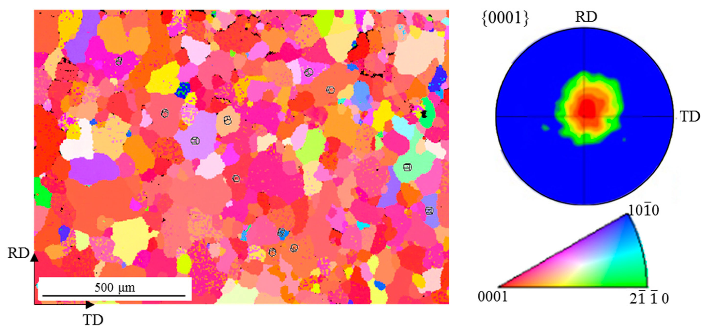
2.2. Microstructure Observation

To thoroughly analyze the crystal orientation of the sample, a technique combining Scanning Electron Microscopy (SEM) with EBSD was employed. The SEM was performed using a Sigma300 produced by the German Zeiss company (Baden-Württemberg, Germany).Prior to the EBSD scanning process, the surface of the sample underwent meticulous mechanical polishing, followed by electrolytic polishing or ion polishing, aimed at eliminating any residual surface stress. In this study, electrolytic polishing with a perchloric acid–alcohol solution (ratio 1:9) was adopted for stress relief. The polishing was conducted at a controlled voltage of 15 V, maintaining a temperature of −20 °C for a precisely timed duration ranging from 10 to 30 s. During the EBSD scanning, the operating voltage was 20 KV, and the working distance was 12 mm. Furthermore, a scanning step size was carefully selected within the range of 0.05 μm to 5 μm to ensure comprehensive data acquisition. Once the EBSD scanning was completed, CHANNEL5 software (v.5.12.74.0) (EBSD analysis software of Oxford Corporation, Shanghai, China) was utilized to meticulously analyze the scanned images, and the key information about grain orientation and grain boundaries on the test surface area of the sample was obtained. Special emphasis was placed on examining the texture through EBSD measurements conducted on the RD–TD (rolling direction–normal direction) surface, as illustrated in Figure 2. It became evident that the majority of grains exhibited an average size of approximately 100 μm. The analysis of pole and inverse pole diagrams indicated the presence of a typical basal texture within the material. Specifically, the <0001> orientation of the majority of the grains aligned predominantly parallel to the ND direction.

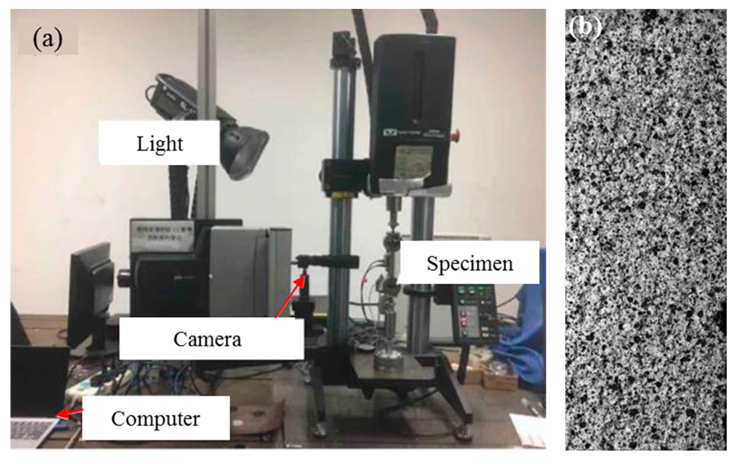
2.3. DIC Setup and Test Procedure

The tensile test was conducted utilizing the INSTRON5848 electronic universal testing machine (Instron Corporation, Norwood, MA, USA). In order to ensure quasi-static loading, the loading rate was set at 0.36 mm/min and the strain rate was 10−3 s−1. Three identical tensile specimens were tested to ensure the repeatable loading of the test results. The testing machine applied a gradually increasing force to the sample, causing it to elongate and ultimately fail at its ultimate tensile strength. Prior to the testing, the sample’s surface was mechanically polished to enhance the visibility during deformation. At the same time, speckle was applied on the opposite of the sample to monitor the deformation during the tensile process. And the strain during the tensile process was obtained by using the DIC technique. This involved initially spraying a uniform layer of white matte paint, followed by a random distribution of 1500 black spray paint particles. During the spraying process, both the distance and duration were meticulously controlled to prevent the formation of excessive density, which could potentially compromise the quality of the resulting spots. This meticulous attention to detail ensured that the sprayed material was evenly distributed and adhered to the surface in a manner that maintained the optimal spot quality, thus facilitating accurate and reliable measurements during the subsequent testing or analysis.
During the testing, a Daheng industrial camera equipped with a macro lens captured the evolving speckle pattern on the test surface. The captured images were then subjected to DIC analysis, a technique that employs advanced algorithms to pinpoint marking points on the specimen’s surface before and after deformation. These points served as the basis for calculating the displacement field, which, in turn, was differentiated to derive the strain field. To ensure accurate deformation tracking, a stable light source illuminated the sample, and the camera was positioned perpendicular to the RD–TD surface. This setup, along with the sample speckle pattern, is depicted in Figure 3.

2.4. In Situ Testing Procedure

To gain a profound understanding of the complexities of micro-deformation and its dynamic evolution within magnesium alloys during tensile testing, a series of meticulously designed in situ tensile experiments were conducted across a range of strains, such as 0.01, 0.02, etc. The experimental setup, elegantly illustrated in Figure 4, featured a Gatan in situ tensile stage that securely held the sample within a high-resolution ZEISS field emission SEM. This innovative integration allowed for the unparalleled ability to observe the sample’s surface in real time, within the pristine vacuum chamber of the SEM, as it was subjected to tensile loading. This direct visualization provided invaluable insights into the material’s behavior at the microscale, enabling a deeper exploration of the intricate interplay between micro-deformation and mechanical stress.
To capture the subtle nuances of microscopic deformation on the sample’s surface, the EBSD technique was employed, providing a detailed map of the material’s microstructure. These data were then rigorously analyzed using CHANNEL5 software, enabling a comprehensive understanding of the microstructural evolution that occurs during tensile testing. The activation behavior of twin crystals plays a pivotal role in shaping the material’s mechanical response. Prior to the commencement of in situ stretching, the sample underwent meticulous mechanical polishing to ensure a smooth and defect-free test surface. This step was crucial in eliminating any residual stress that might have arisen from previous electrolysis polishing, ensuring that the observed deformation behavior was solely a result of the applied tensile load.

3. Results

3.1. Macroscopic Mechanical Properties

During the in situ tensile test, the experiment was paused at specific strain levels of 1%, 2%, 5%, and ultimately 12%, where the sample sustained damage. The true strain of the sample was loaded to 1% and then unloaded. After scanning the microstructure of the sample, the sample was re-loaded to 2% at the same rate, and then unloaded for scanning the microstructure. The previous steps were repeated successively to obtain the microstructure with true strains of 1%, 2%, 5%, and 12%. When the test was interrupted, the specimens all had plastic deformation, so there was no elastic rebound after unloading. The unloading section and elastic section of the discontinuity curve were removed, and the real stress–strain curve was obtained through data processing, as shown in Figure 5. Three points, a, b, and c, in the figure are discontinuity points, and the sample is broken at d. During the uniaxial tensile test, the strain field distribution on the RD–TD surface of the tensile specimen was obtained by using the DIC technique. The true strain of the sample was obtained via a strain field calculation. In order to directly reflect the microscopic evolution of the sample during the uniaxial tensile process, strain cloud maps in the TD direction with true strains of 1%, 2%, 5%, and 12% are also placed in Figure 5.
The strain cloud map results show that after yielding, the strain on the specimen surface shows obvious non-uniformity, as shown at point a in Figure 5. With the increase in strain, obvious cross-shear bands were generated on the specimen surface, which showed an obvious 45° angle with the tensile direction, were dispersed in the direction and narrow in width, and evenly distributed on the specimen surface, as shown at point b in Figure 5. As the loading strain increased, these shear bands underwent stable expansion, effectively dispersing the strain concentration, as shown at point c in Figure 5. This dispersion significantly weakened the intensity of the strain concentration, fostering stable plastic deformation within the material [22]. However, as the strength of these shear bands intensified and shear bands from various directions intersected and traversed the specimen’s surface, the material’s integrity was compromised, ultimately leading to specimen failure.

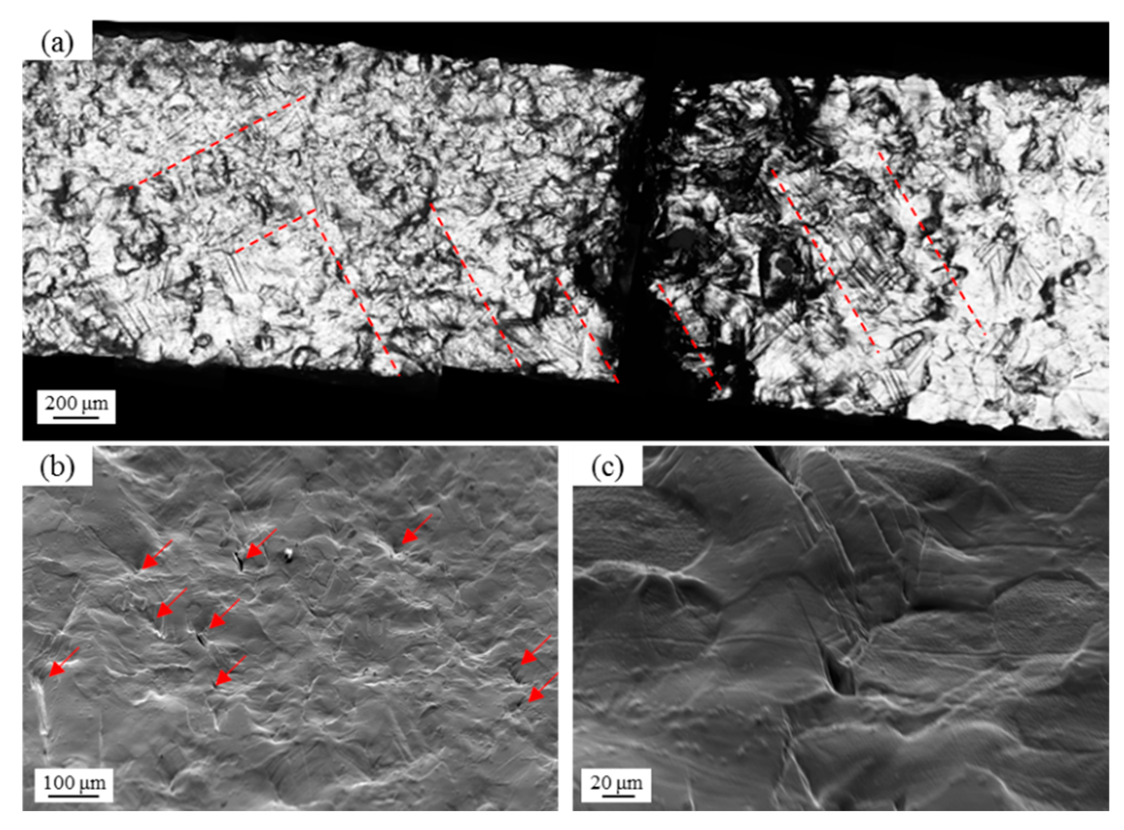
3.2. Failure Morphology

Prior to the tensile test, the specimen’s surface was carefully mechanically polished to achieve a mirror-like finish, ensuring that any subsequent morphological changes after failure would accurately reflect its plastic deformation behavior. To capture these deformations, both optical microscopy and SEM were employed, with the results presented in Figure 6. Figure 6a demonstrates that in the vicinity of the fracture, severe plastic deformation was evident, concentrated within a cross-distributed area oriented at a 45° angle to the tensile direction, as highlighted by the red dashed line. This observation aligned perfectly with the strain field analysis of shear bands, reinforcing the notion that the plastic deformation during the tensile process is non-uniform, primarily localized in shear bands oriented at 45° to the tensile axis. Zooming in on one of the clipped regions in Figure 6b revealed a dense network of slip lines within the shear region, accompanied by numerous “tongue”-shaped cracks (indicated by red arrows). These “tongue”-shaped cracks are associated with twins. When the crack front encountered twin crystals, it deflected from its original path, separating the twins from the matrix, thereby giving rise to the characteristic “tongue” pattern [23]. These characteristics indicate that the twin crystals have a higher density in the shear region.
To further delve into the microstructural details, a cracking area was magnified, as shown in Figure 6c. Here, it became apparent that cracks predominantly initiated at the intersections of grain boundaries and trace lines. Notably, twin boundaries, being a special type of grain boundary, exhibited limited deformation coordination capabilities within the grain boundary region. Consequently, the junction of twin boundaries and grain boundaries became a preferential site for crack initiation, ultimately impacting the material’s plasticity.

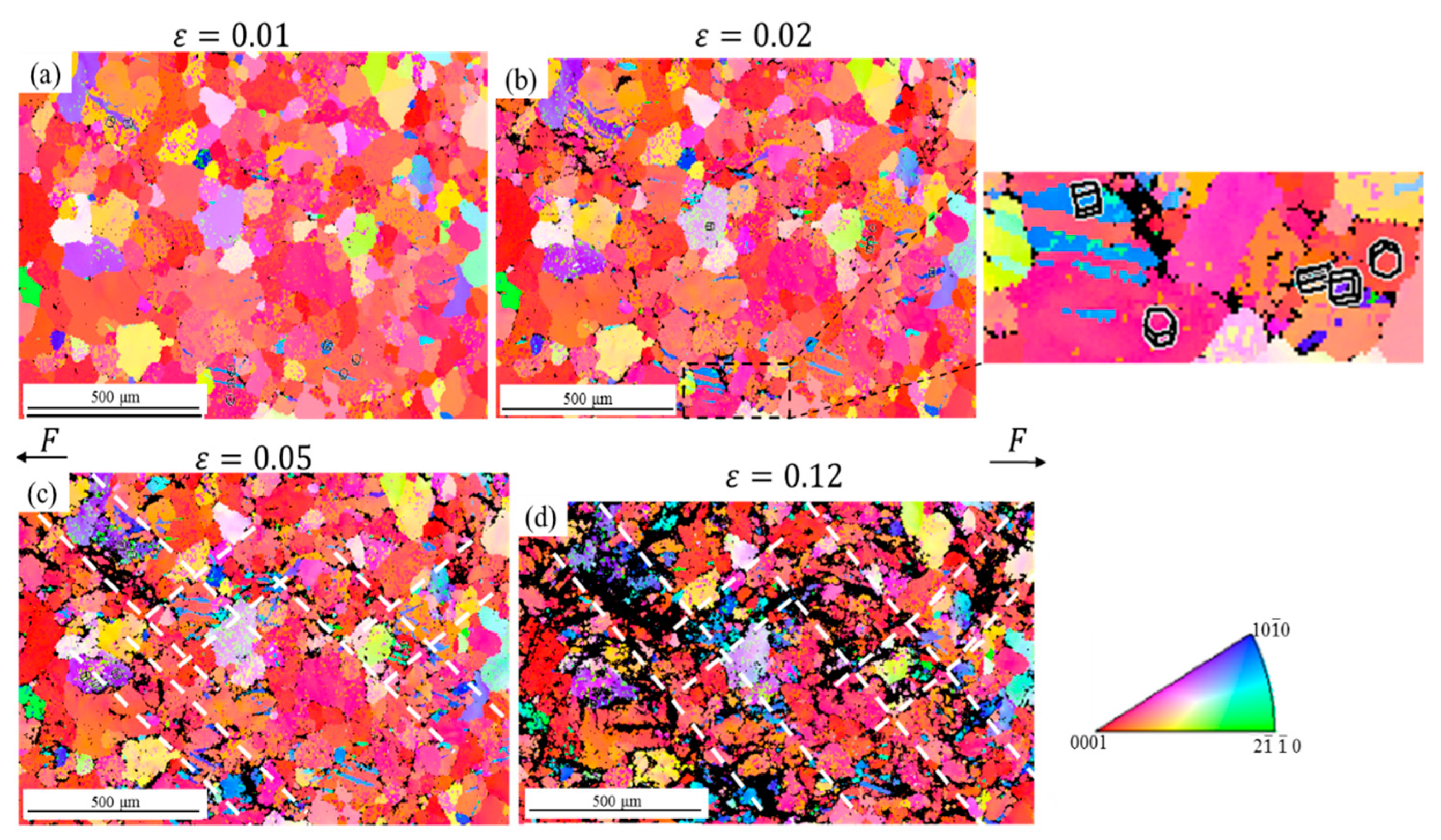
3.3. Microstructure Evolution

To investigate the macroscopic deformation characteristics of magnesium alloys under tensile loading and gain deeper insights into the microstructural transformations, particularly the activation patterns of twins within the deformation zone, CHANNEL5 software was employed to scrutinize the scanning images and quantify the microscopic deformation responses of the samples across varying loading strains. Figure 7 illustrates these findings, with arrows clearly marking the direction of loading. At a true strain of 0.01, the material initiates yielding, transitioning into the plastic deformation regime, wherein initial twinning within selected grains was observed as shown in Figure 7a. As the strain escalated to 0.02, a notable increase in the width and density of twins was evident, accompanied by a significant grain reorientation, primarily manifesting as a ~57° rotation along the C-axis, indicative of a compressive twin as shown in Figure 7b. This information could be observed in the enlarged image to the right of Figure 7b. Further straining to 0.05 prompted an expansion in the twinning phenomenon, with a pronounced concentration of twins forming along the shear direction, constituting a distinct twin concentration zone as shown in Figure 7c. Upon reaching a strain of 0.12, the sample exhibited signs of damage, marked by severe plastic deformation within the twin bands. This underscores the proliferation of high-density twins in grains aligned along the shear direction of the AZ31 magnesium alloy during uniaxial tensile testing. The observed microstructural evolution was consistent with the failure morphology, highlighting the severity of deformation along the shear axis.
To delve deeper into the microstructural transformations of the AZ31 magnesium alloy subjected to uniaxial tension, our analysis focused on the dislocation density distribution within the in-situ monitoring region. By processing the EBSD scanning outcomes from the in-situ experiments, we generated KAM (Kernel Average Misorientation) diagrams for varying loading strains, which provided a statistical portrayal of the local orientation variations among the grains, as shown in Figure 8. The result showed that the dislocation density escalated progressively as the loading strain intensified, with a pronounced concentration observed along the shear direction. Notably, at strains of 0.01 and 0.02, a high-density dislocation zone emerged, aligning seamlessly with the twin concentration zone depicted in Figure 7 in terms of both direction and width. As the loading strain advanced to 0.05, the dislocation density within this concentrated band intensified further. Ultimately, at a strain of 0.12, the average KAM value surpassed 1.1°, indicative of a heightened dislocation density across the entire sample. These observations underscored the significant role played by the dislocation activity, particularly along the shear direction, in the microstructural evolution of the AZ31 magnesium alloy under uniaxial tension.

4. Discussion

The rolled AZ31 magnesium alloy plate itself has a substrate texture, and when stretched along the C-axis of the grain (the grain is mainly parallel to the ND and TD directions), the C-axis is compressed. This compression satisfies the preconditions of atomic configuration for the formation of compressive twins and is conducive to the formation of high-density compressive twins along the shear direction. At the same time, the formation of twins also requires the flow stress of the material to reach its critical stress. In the uniaxial tensile process, the yield stress of the material is higher than 135 MPa, and the shear stress reaches the peak value when the tensile direction is 45°, and the critical stress of activating the compression twin is easily reached. Therefore, compressive twins are activated when stretched along the C-axis of the grain. The appearance of these compressive twins excites the shear deformation, resulting in a large amount of strain accumulation in the shear direction, forming a shear band. At the same time, due to the diffusion of the slip channel caused by local twins, the dislocation density in the shear band increases, which promotes the generation of additional dislocations. Therefore, the interaction between twins and local grain dislocations eventually leads to the formation of microscopic shear bands, resulting in strain heterogeneity on the specimen surface.
To scrutinize the nature of slip phenomena, attention was focused on calculating the Schmidt factors for both the basal and prismatic slip systems in the initial sample, with the results presented in Figure 9. The figure reveals that the majority of the grains in the pristine sample exhibited a high Schmidt factor favoring basal plane slip, indicating a prevalent occurrence of basal plane slip across these grains. Conversely, the distribution of Schmidt factors for prismatic slip showed obvious directivity, which aligned well with the orientation and extent of shear bands. In the initial to intermediate stages of tensile deformation, the AZ31B magnesium alloy primarily underwent basal plane slip in most grains. However, grains oriented along the shear direction exhibited a dual-mode deformation characterized by both twinning and prismatic slip. Notably, the dislocation density within the shear zone grains was elevated, indicative of the pronounced deformation in these regions. As the deformation progresses to later stages, the dislocation density within the majority of the grains surged, while the defect density in the shear zone grains gradually reached saturation, ultimately leading to material failure.
Compared with other metal materials, the asymmetric crystal structure of magnesium leads to the formation of texture in the forming process of its alloy materials, and the strain will be heterogeneous in the tensile loading in a specific direction. The combined effect of loading direction and texture leads to strain localization of the AZ31B magnesium alloy. The strain distribution in different loading directions can be studied later to provide guidance for engineering applications. Twin and dislocation can also be introduced through pre-deformation treatment to make the plastic deformation more uniform, avoid strain localization, and improve the plasticity of the material.

5. Conclusions

The deformation behavior of the AZ31B magnesium alloy subjected to uniaxial tensile loading at room temperature was meticulously investigated through an in situ experimental approach, coupled with an analysis of the strain field distribution and microstructural evolution. The main conclusions are as follows.
(1)
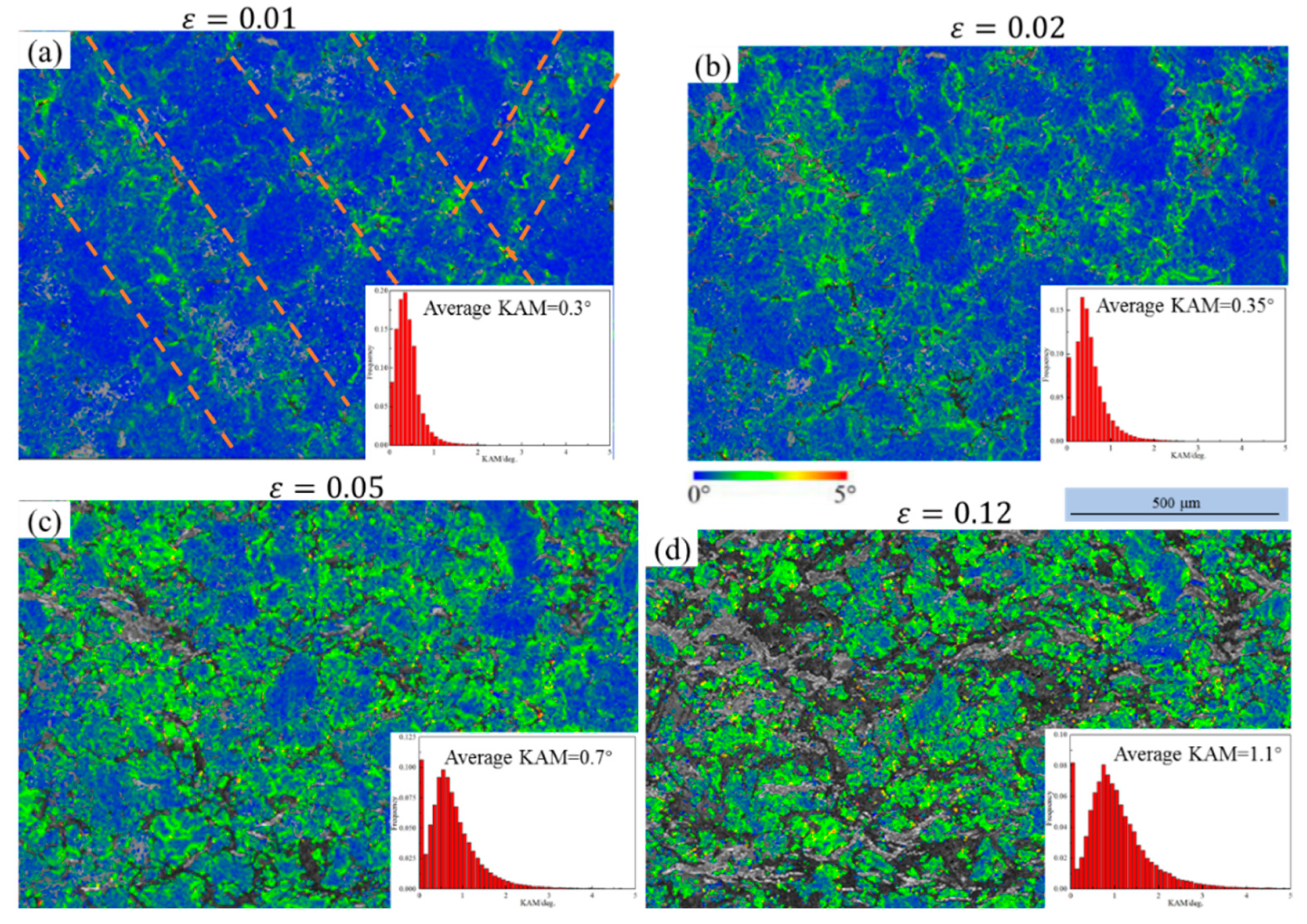
During the uniaxial tensile loading process, the AZ31B magnesium alloy surface exhibited a densely packed network of discrete shear bands, which effectively mitigated the strain concentration, facilitating stable plastic deformation. However, as the strength of these shear bands intensified, reaching the ultimate strength threshold of the sample, the material underwent catastrophic failure upon the intersection and surface manifestation of shear bands oriented in diverse directions.
(2)
In situ tensile testing and microscopic examination revealed that the deformation zone originated from twins within localized grains, emphasizing the pivotal role of com-pressive twinning. The high density of the twins within the deformation bands enhanced the dislocation slip pathways, leading to intense deformation. As the twins grew towards the grain boundaries, they encountered difficulties in coordinating de-formation, triggering the initiation of microcracks at the grain interfaces. Subsequently, with the progression of plastic deformation, these microcracks proliferated and coalesced, ultimately causing material failure.
(3)
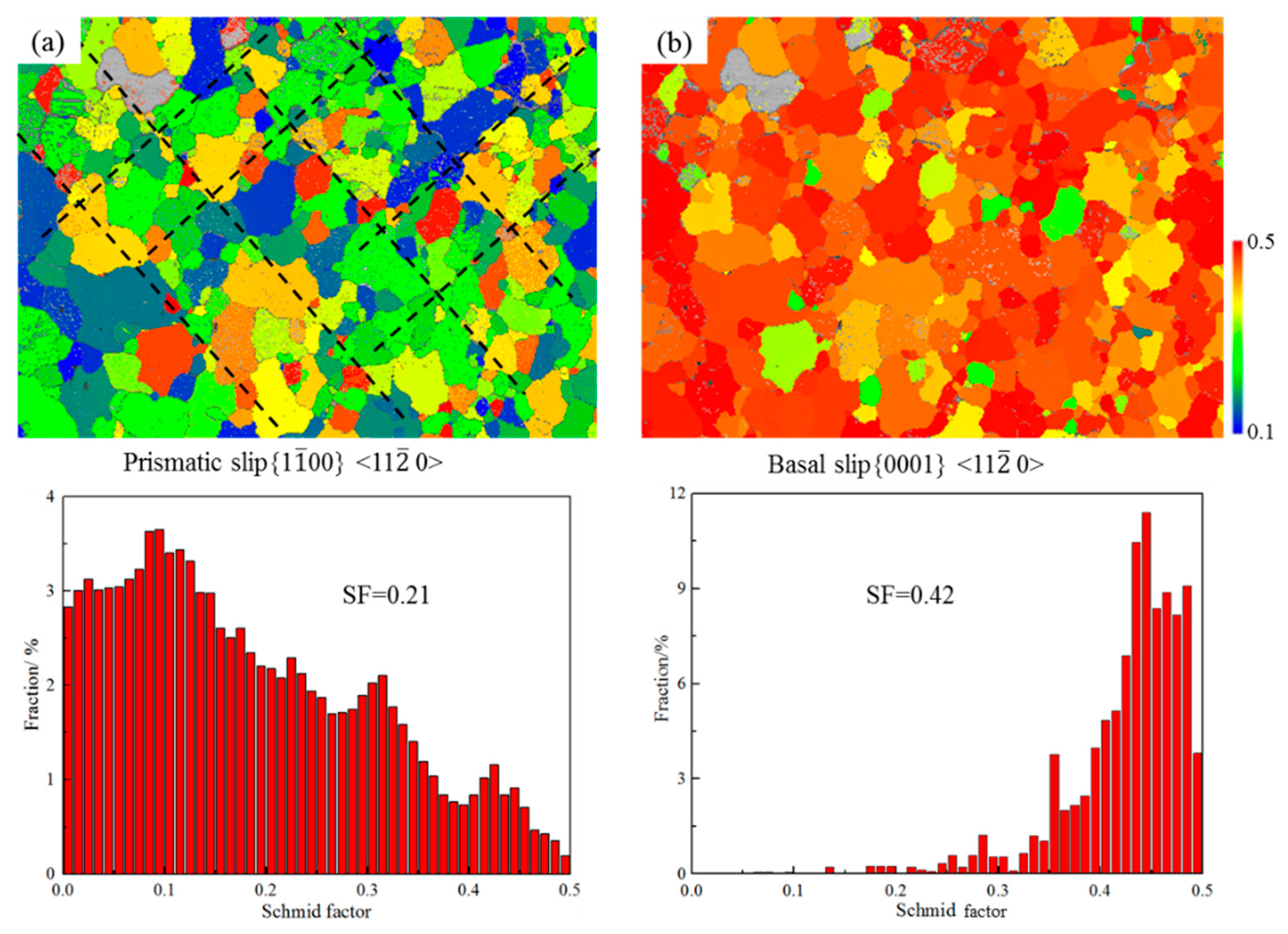
An analysis of the Schmidt factors in the initial sample illuminated the directional nature of the prismatic slip within grains. Notably, localized enhancements in prismatic slip intensified the formation of intersecting shear bands, thereby coordinating material deformation in a harmonious manner.

Author Contributions

Conceptualization, Q.Z. and X.Z.; methodology, Q.Z.; software, Q.Z.; validation, Q.Z. and X.Z.; investigation, Q.Z. and X.Z.; resources, Q.Z.; data curation, X.Y.; writing—original draft preparation, Q.Z. and X.Z.; writing—review and editing, Q.Z. and X.Z.; visualization, X.Z.; supervision, X.Y.; project administration, M.H.; funding acquisition, M.H. All authors have read and agreed to the published version of the manuscript.

Funding

This research was funded by Min Huang funding number 2024JC-YBQN-0372.

Institutional Review Board Statement

Not applicable.

Informed Consent Statement

Not applicable.

Data Availability Statement

The raw data supporting the conclusions of this article will be made available by the authors on request.

Acknowledgments

The authors wish to express their gratitude to Aircraft Structural Mechanics and Strength Technology Laboratory, Northwestern Polytechnical University.

Conflicts of Interest

The authors declare no conflicts of interest.

References

  1. Zhong, C.; Liu, F.; Wu, Y.; Le, J.; Liu, L.; He, M.; Zhu, J.; Hu, W. Protective diffusion coatings on magnesium alloys: A review of recent developments. J. Alloys Compd. 2012, 520, 11–21. [Google Scholar] [CrossRef]
  2. Mordike, B.; Ebart, T. Magnesium: Properties-applications-potential. Mater. Sci. Eng. A 2001, 302, 37–45. [Google Scholar] [CrossRef]
  3. Liu, Q. Research progress on plastic deformation mechanism of Mg alloys. Acta Metall. Sin. 2010, 48, 1458–1472. [Google Scholar] [CrossRef]
  4. Styczynski, A.; Hartig, C.; Bohlen, J.; Letzig, D. Cold rolling textures in AZ31 wrought magnesium alloy. Scr. Mater. 2004, 50, 943–947. [Google Scholar] [CrossRef]
  5. Malik, A.; Wang, Y.; Nazeer, F.; Khan, M.A. Effect of pre-compression on changes in texture and yielding behavior of ZK61 Mg alloy. Vacuum 2020, 172, 109039. [Google Scholar] [CrossRef]
  6. Cottam, R.; Robson, J.; Lorimer, G.; Davis, B. Dynamic recrystallization of Mg and Mg-Y alloys: Crystallographic texture development. Mater. Sci. Eng. A 2008, 485, 375–382. [Google Scholar] [CrossRef]
  7. Agnew, S.R.; Brown, D.W.; Tomé, C.N. Validating a polycrystal model for the elastoplastic response of magnesium alloy AZ31 using in situ neutron diffraction. Acta Mater. 2006, 54, 4841–4852. [Google Scholar] [CrossRef]
  8. Beyerlein, I.J.; McCabe, R.J.; Tomé, C.N. Effect of microstructure on the nucleation of deformation twins in polycrystalline high-purity magnesium: A multi-scale modeling study. J. Mech. Phys. Solids 2011, 59, 988–1003. [Google Scholar] [CrossRef]
  9. Khan, A.; Pandey, A.; Gnäupel-Herold, T.; Mishra, R.K. Mechanical response and texture evolution of AZ31 alloy at large strains for different strain rates and temperatures. Int. J. Plast. 2011, 27, 688–706. [Google Scholar] [CrossRef]
  10. Knezevic, M.; Levinson, A.; Harris, R.; Mishra, R.K.; Doherty, R.D.; Kalidindi, S.R. Deformation twinning in AZ31: Influence on strain hardening and texture evolution. Acta Mater. 2010, 58, 6230–6242. [Google Scholar] [CrossRef]
  11. Jiang, J.; Godfrey, A.; Liu, W.; Liu, Q. Microtexture evolution via deformation twinning and slip during compression of magnesium alloy AZ31. Mater. Sci. Eng. A 2008, 483–484, 576–579. [Google Scholar] [CrossRef]
  12. Jiang, L.; Jonas, J.; Luo, A.; Sachdev, A.K.; Godet, S. Influence of {10–12} extension twinning on the flow behavior of AZ31 Mg alloy. Mater. Sci. Eng. A 2007, 445–446, 302–309. [Google Scholar] [CrossRef]
  13. Zhang, W.; Ye, Y.; He, L.; Li, P.; Zhang, H. Dynamic mechanical response and microstructural evolution of extruded Mg AZ31B plate over a wide range of strain rates. J. Alloys Compd. 2017, 696, 1067–1079. [Google Scholar] [CrossRef]
  14. Martin, É.; Capolungo, L.; Jiang, L.; Jonas, J.J. Variant selection during secondary twinning in Mg-3% Al. Acta Mater. 2010, 58, 3970–3983. [Google Scholar] [CrossRef]
  15. Mu, S.; Jonas, J.J.; Gottstein, G. Variant selection of primary, secondary and tertiary twins in a deformed Mg alloy. Acta Mater. 2012, 60, 2043–2053. [Google Scholar] [CrossRef]
  16. Wang, F.; Sandlöbes, S.; Diehl, M.; Sharma, L.; Roters, F.; Raabe, D. In situ observation of collective grain-scale mechanics in Mg and Mg–rare earth alloys. Acta Mater. 2014, 80, 77–93. [Google Scholar] [CrossRef]
  17. Kapan, E.; Shafaghi, N.; Uc̣ar, S.; Aydıner, C.C. Texture-dependent character of strain heterogeneity in Magnesium AZ31 under reversed loading. Mater. Sci. Eng. A 2017, 684, 706–711. [Google Scholar] [CrossRef]
  18. Hazeli, K.; Cuadra, J.; Vanniamparambil, P.A.; Kontsos, A. In situ identification of twin-related bands near yielding in a magnesium alloy. Scr. Mater. 2013, 68, 83–86. [Google Scholar] [CrossRef]
  19. Sandlöbes, S.; Zaefferer, S.; Schestakow, I.; Yi, S.; Gonzalez-Martinez, R. On the role of non-basal deformation mechanisms for the ductility of Mg and Mg-Y alloys. Acta Mater. 2011, 59, 429–439. [Google Scholar] [CrossRef]
  20. Agnew, S.; Tomé, C.; Brown, D.; Holden, T.; Vogel, S. Study of slip mechanisms in a magnesium alloy by neutron diffraction and modeling. Scr. Mater. 2003, 48, 1003–1008. [Google Scholar] [CrossRef]
  21. Zhang, X.; Xu, Y.; Li, W.; Yan, Z.; Hu, P.; Liu, X. Microstructure Characterization and Mechanical Properties of an AM60B Magnesium Alloy Sheet Prepared by the Double-Pass High Strain Rate Rolling with Gradient Cooling. Adv. Eng. Mater. 2021, 23, 2000625. [Google Scholar] [CrossRef]
  22. Wang, Y.; Huang, C.; Li, Y.; Guo, F.; He, Q.; Wang, M.; Wu, X.; Scattergood, R.O.; Zhu, Y. Dense dispersed shear bands in gradient-structured Ni. Int. J. Plast. 2020, 124, 186–198. [Google Scholar] [CrossRef]
  23. Zhong, Q.; Zhao, Z. Fractography; Higher Education Press: Beijing, China, 2006; pp. 122–153. [Google Scholar]
Figure 1. Sample orientation diagram.
Applsci 15 01571 g001
Figure 2. EBSD map on the RD–TD plane of the magnesium AZ31 rolled plate.
Applsci 15 01571 g002
Figure 3. (a) Drawings of experimental installations; (b) sample speckle pattern.
Applsci 15 01571 g003
Figure 4. In situ test device.
Applsci 15 01571 g004
Figure 5. Macroscopic stress–strain curve and DIC test results.
Applsci 15 01571 g005
Figure 6. Failure morphology of the sample. (a) The appearance near the fracture; (b) The dense network of slip lines within the shear region; (c) Enlarged view of the crack region.
Applsci 15 01571 g006
Figure 7. EBSD map of a representative area under different strains. (a) At 0.01 strain; (b) At 0.02 strain; (c) At 0.05 strain; (d) At 0.12 strain.
Applsci 15 01571 g007
Figure 8. KAM map of a representative area under different strains. (a) At 0.01 strain; (b) At 0.02 strain; (c) At 0.05 strain; (d) At 0.12 strain.
Applsci 15 01571 g008
Figure 9. Schmidt factor of a representative area in the original sample. (a) Schmidt factor of prismatic slip; (b) Schmidt factor of basal slip.
Applsci 15 01571 g009
Disclaimer/Publisher’s Note: The statements, opinions and data contained in all publications are solely those of the individual author(s) and contributor(s) and not of MDPI and/or the editor(s). MDPI and/or the editor(s) disclaim responsibility for any injury to people or property resulting from any ideas, methods, instructions or products referred to in the content.

