Article

Experimental Study on Grouting Diffusion Law of Tunnel Secondary Lining Cracks Based on Different Slurry Viscosities

1
State Key Laboratory of Mountain Bridge and Tunnel Engineering, Chongqing Jiaotong University, Chongqing 400074, China
2
School of Civil and Hydraulic Engineering, Chongqing University of Science and Technology, Chongqing 401331, China
3
Chongqing Underground Application Research Institute Co., Ltd., Chongqing 401120, China
4
Institute of Future Civil Engineering Science and Technology, Chongqing Jiaotong University, Chongqing 400074, China
*
Authors to whom correspondence should be addressed.
Appl. Sci. 2025, 15(4), 1955; https://doi.org/10.3390/app15041955
Submission received: 3 January 2025 / Revised: 9 February 2025 / Accepted: 11 February 2025 / Published: 13 February 2025

Abstract

:

Featured Application

The relevant research results have been applied in the treatment of subway diseases in Chongqing.

Abstract

To investigate the diffusion law of ultrafine cement slurry (UCS) with different water–cement ratios in tunnel second lining cracks during grouting, the grouting of ultrafine cement slurry with different water–cement ratios was carried out by experimental and theoretical analysis methods in this study. Through the collection and data analysis grouting experiment of the diffusion time history, the diffusion morphological characteristics based on different slurry viscosities were obtained, which were divided into three grouting diffusion patterns: circular diffusion zone, excessive diffusion zone, and elliptical diffusion zone. Furthermore, the spatiotemporal variation rules of the diffusion radius of ultrafine cement slurry with different water–cement ratios in tunnel secondary lining cracks were obtained as well. By analyzing the diffusion radius values under different water–cement ratios in each direction of x+, x−, y+, and y−, the critical water–cement ratios ξ were found to be 0.8, which affected the diffusion radius value in the vertical upward y+ direction. Meanwhile, when the grouting was completed, the maximum diffusion radius of the ultrafine cement slurry was obtained using different water–cement ratios in each direction. Moreover, the grouting diffusion equation of tunnel secondary lining cracks based on ultrafine cement slurry with different water–cement ratios is established. The research results can accurately predict the grouting diffusion pattern and diffusion radius in tunnel second lining cracks with different water–cement ratios of ultrafine cement slurry.

1. Introduction

China’s tunnel has seen unprecedented growth in terms of number, size, and construction speed. However, this rapid expansion has led to an increase in tunnels operating under suboptimal conditions, with issues such as seepage in tunnel lining structures posing significant operational risks to safety [1,2,3,4]. The causes of water leakage in tunnel lining structures are numerous, involving geological conditions, design parameters, construction techniques, and operational environments. As a result, cracks and other defects in operational tunnel linings are quite common [5,6,7,8,9]. At the same time, the tunnel lining cracking, water seepage, and hanging ice are common phenomenon. There are still cracking and seepage on the defect area if tunnel lining crack treatment is not completed; therefore, the tunnel lining cracks have become a world problem of the current tunnel disease treatment [10,11,12]. To prevent the corrosion of reinforced steel in the tunnel lining, and to ensure that the lining structure has sufficient long-term stability, it is necessary to repair the tunnel second lining cracks promptly. Tunnel secondary lining crack repair by the drilling–grouting method, and the mechanical properties of the grouting material, the slurry diffusion law, and the grouting design parameters determine the effect of lining crack repair [11,13,14,15,16,17].
The current research in this field focuses on the construction process of tunnels, the materials used for grouting, and the diffusion law in the context of challenging geological conditions. However, there is a notable absence of attention paid to the operational aspects of tunnel lining, particularly, the mechanical properties of grouting materials used for repairing cracks in tunnel linings and the diffusion law governing the movement of these materials within the cracks. In terms of geotechnical fissure grouting, for example, Jian et al. [18,19] studied the diffusion mechanism of C-S slurry based on the viscosity–time variation and derived the diffusion equation of C-S slurry, which provides theoretical support for the design of the parameters of C-S slurry in the process of geotechnical grouting; Liu et al. [20,21] investigated the horizontal diffusion characteristics of slurry under dynamic water conditions, revealed the diffusion law of slurry in geotechnical grouting slurry under dynamic water conditions; Zhou et al. [22] investigated the diffusion law of slurry under a constant flow rate and constant grouting pressure, which provides a research idea to study the diffusion law of slurry in tunnel lining cracks. In terms of grouting fluid theory, due to the different fluid properties of slurry, Zhang et al. [23] established a diffusion step-by-step algorithm for Bingham fluid slurry based on the coupling effect of slurry and rock and investigated the diffusion law of the slurry in the cracks of the rock mass; Hag J et al. [24,25] built a grout diffusion model to conduct diffusion tests on cement grouting materials for Bingham fluids and obtained grout diffusion lengths. Luo et al. [26,27] carried out an atheoretical study of the Bingham slurry flow model for monoclinic fissures. Zhou et al. [28] derived the diffusion radius of the Newtonian fluid in the soil in split grouting; Li et al. [29] established an analytical equation for the diffusion radius about the self-expansion of slurry, these studies provided an effective calculation theoretical method to describe the diffusion radius of slurry in the cracks. The relationship between grouting pressure and the diffusion law was constructed by the effect of grouting pressure on diffusion in cracks. Wu et al. [30,31,32] theoretically analyzed a variety of grouting materials and investigated the influence law of grouting pressure and splitting characteristics on the diffusion pattern. Jiang et al. [33,34] analyzed the slurry change law of grouting pressure, the slurry flow law, and the grouting diffusion law of surface by experiments. Their research on grouting slurry diffusion, including slurry types and pressure, has provided useful insights and new methods for studying tunnel secondary lining crack grouting.
Research on the characteristics of grouting slurry in tunnel secondary lining cracks, the diffusion law of the slurry, the mechanical properties of the material after condensation, and the design parameters of grouting are still in its infancy. How the grouting slurry diffuses in the cracks of the tunnel’s second lining with time is less reported in the current research. The research on the grouting repair of tunnel second lining cracks is based on geotechnical grouting theory and research results. In recent years, Zhang et al. [16,35] carried out some research on the cement grouting material properties and the grout diffusion process of the slurry in the tunnel second lining cracks, constructed the grout diffusion model of the tunnel second lining cracks, and put forward the equation of the diffusion of the slurry for the repair of grouting in the tunnel second lining cracks. In this research, the tunnel second lining crack grouting model test is used to study the diffusion pattern of slurry in tunnel second lining cracks under different water–cement ratios, the change rule between the radius of grout diffusion R and time T , and the critical water–cement ratio of the range of slurry diffusion in the direction of inverse gravity and other issues. The research results provide theoretical support for the design and construction of grouting repair in tunnel second lining cracks.

2. Grouting Diffusion Test for Tunnel Second Lining Cracks

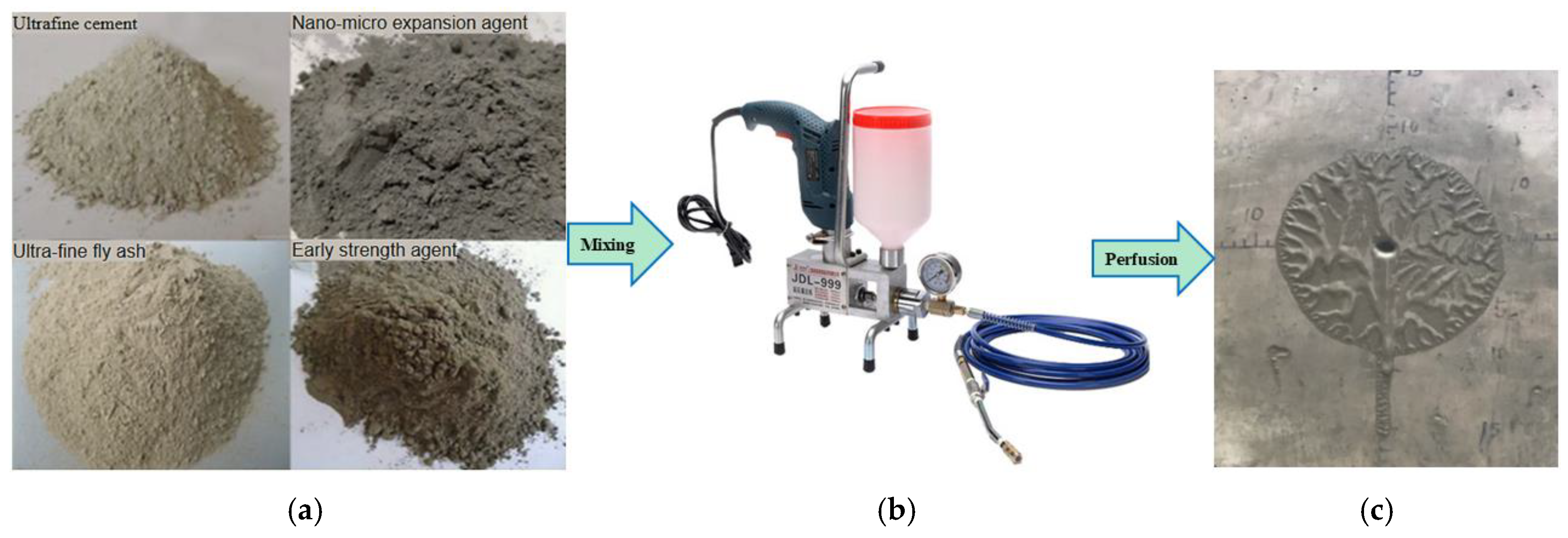
2.1. Material Parameters

Cement as a binder and added certain admixtures to it can enhance the mechanical properties of the cement slurry [16,35]. Added ultrafine cement, ultrafine fly ash, nano-micro-expanders, and early strengthening agents can improve the mechanical properties of grouting. The different test materials are illustrated in Figure 1.
Experimental research has demonstrated that incorporating a specific proportion of fly ash into ultrafine cement can enhance the fluidity of grouting slurry, thereby significantly improving its injectability. Additionally, the use of nano-micro-expanders has been shown to stabilize the slurry, accelerate stone formation, and minimize stone body shrinkage. The optimized material mix, derived from extensive comparative testing, is detailed in Table 1.

2.2. Slurry Initial Viscosity Test

To investigate the impact of the water–cement ratio on diffusion, we conducted a series of experiments with fixed crack width, grouting pressure, and crack plane inclination. As detailed in Table 2, water–cement ratios of 0.5, 0.6, 0.7, 0.8, 0.9, and 1.0 were examined across five test sets.
The water–cement ratio is an important influence on the rheological properties of cement-based grouting materials. If the water–cement ratio is too small, the material flow performance will be poor; if the water–cement ratio is too large, the material flow is relatively good, but the grouting material’s caking rate, strength, and permeability will be affected to some extent. By adjusting the water–cement ratio to achieve control of the fluidity of the grouting material, when the water content in the slurry reaches the critical water content W0, the slurry has good fluidity and can produce a good lubrication effect. According to the range of the grouting material ratio, analyzing the rheological properties of different water–cement ratios, the test design of the water–cement ratio changes from 0.5 to 1.0 every 0.1 for a change in the difference, and the slurry viscosity test temperature is 20 degrees Celsius. The rheological curves of slurry with different water–cement ratios are shown in Figure 2.
From Figure 2a, it can be seen that the shear stress is positively related to the shear rate, and the minimum value of the initial shear stress τ0 is 0.12 Pa, which indicates that the type of ultrafine cement slurry is Bingham fluid; from Figure 2b, the viscosity is inversely related to the shear rate.
The viscosity value is one of the factors that affects the spreading of the slurry, and the water–cement ratio affects the initial viscosity of the slurry, and the crack grouting materials commonly used the water–cement ratio of 0.5–1.0, the rheological curves were tested by the rheometer, the Bingham model was used for fitting analysis, and the initial viscosity values of slurries with different water–cement ratios were tested and obtained, as shown in Table 3.
An analysis of the rheological curve shown in Figure 2b reveals that the initial viscosity of the slurry decreased progressively from 33.6 (mPa·s) to 1.80 (mPa·s) as the water–cement ratio was increased from 0.5 to 1.0. This variation in the water–cement ratio led to notable changes in the viscosity parameters of the cement grouting material.

2.3. Tunnel Second Lining Crack Modeling

The experimental setup consists of a custom-designed tunnel secondary lining structure model, constructed using C30 concrete. The model was cast in stages to create interlocking seams. Initially, a model with dimensions of 1.25 m in height, 0.5 m in width, and 0.4 m in thickness (Model No. 1) was cast. After curing Model No. 1, a second model (Model No. 2) with the same height and width but a thickness of 0.1 m was cast adjacent to Model No. 1 along its thickness direction. This process simulated the construction joint with tightly fitting seams. The experimental model is illustrated in Figure 3.

2.4. Experimental Method and Process

The test model employs a two-lined straight crack, with the fracture surface treated as a plane, allowing the slurry to diffuse along the fracture interface. The grouting experiment was conducted at a temperature of 20 degrees Celsius, according to the following steps outlined in the test program:
(1)
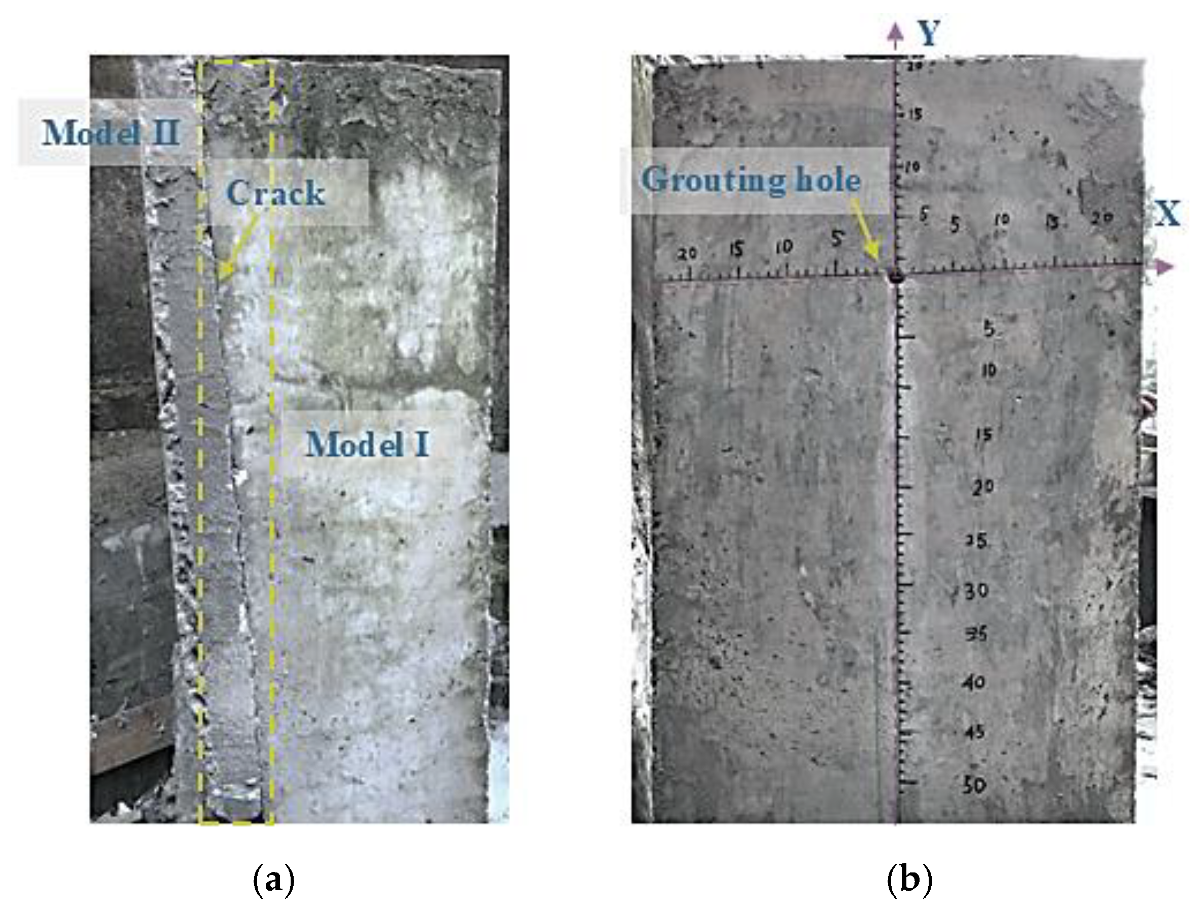
Carry out mechanical drilling at 20 cm from the top of Model Ⅰ, with the direction of drilling being the direction normal to the cross-section of the fissure and install the grouting needles tightly after the drilling is completed and carry out the sealing treatment to ensure that there is no leakage of slurry in the process of grouting.
(2)
To precisely capture the morphology of slurry transport during diffusion, a right-angle coordinate system was meticulously inscribed on the test model with the grouting hole as the origin O. In this system, the X coordinates extend horizontally, while the Y coordinates extend vertically downward, as illustrated in Figure 3b.
(3)
The crack width was set to be 0.4 mm, which was controlled by placing a washer between Model Ⅰ and Model Ⅱ.
(4)
Experiment adopted a high-pressure cement slurry grouting machine, and this machine output the maximum pressure was 12,000 Psi; the slurry was injected into the face where the crack was located by means of a grouting needle, and the rate of slurry injection was recorded.
(5)
During the grouting process, Model Ⅱ was turned on and the spreading pattern and transport distance of the slurry were photographed every 2.5 s. After clearing the slurry between the crack and the grouting machine, then we continue to be closed Model Ⅱ repeat the above steps.

3. Analysis of Test Results

3.1. Diffusion Pattern of Grouting with Different Water–Cement Ratios

Slurry diffusion involves the complex interplay of flow and phase change processes. The slurry diffusion morphology diagram provides a precise depiction of how the slurry diffuses at various moments, offering an intuitive analysis of the slurry diffusion patterns during the grouting process.
The test time was determined to be 25 s through the pre-grouting test and to obtain the diffusion morphology at different moments. The No. 2 Model was opened at the moments of 2.5 s, 5 s, 7.5 s, 10 s, 15 s, 20 s, and 25 s, and the diffusion morphology was recorded, and the diffusion trajectory and morphology were analyzed by using the image processing software (AutoCAD 2020). Analyzing the effect of different water–cement ratios on the radius of grout diffusion, the experimental data on the grouting process of different ultrafine cementitious slurry viscosities were collected to obtain the diffusion patterns of different water–cement ratios (‘W/C = ξ’, or different slurry viscosities) for the second lining of the tunnel, and the experimental results are shown in Figure 4.
It can be seen from the diffusion pattern in Figure 4, the process of slurry diffusion can be divided into three stages: a round diffusion area, excessive diffusion area, and asymmetric elliptic diffusion area, the diffusion radius increasing with time. The test aims to obtain the diffusion patterns of slurries with different water–cement ratios at various moments. These patterns will be comparatively analyzed at the same moment, from which the variation rules of the diffusion patterns of slurries with different water–cement ratios at a certain moment can be derived.
In the diffusion pattern in Figure 4, it can be seen that in the beginning of grouting to 2.5 s or less, due to the small amount of injected slurry, the diffusion pattern is a circular diffusion zone; in the time period of 2.5 s to 5 s, the amount of injected slurry gradually becomes bigger, and under the joint action of viscosity and gravity, the slurry changes from a circular to elliptical diffusion pattern, which can be called the over-diffusion zone; in the time period of 5 s to 25 s, the amount of injected slurry is gradually increased by the action of gravity, and the slurry diffusion pattern is an elliptical diffusion zone.
From Figure 4a–f, it can be concluded that the diffusion radius in the x+, x−, y+, and y− directions, under the conditions of different parameters of grouting materials with different water–cement ratios, tends to become larger with the increase in the water–cement ratio (increases with the decrease in viscosity). In terms of morphology, the diffusion radius in the x+, x− direction is approximately symmetric, the vertical direction is affected by gravity, and the diffusion radius in the y+, y− direction is asymmetric in the up and down directions.

3.2. Slurry Diffusion Radius Time Profile Analysis

The time-course variation curves of the diffusion radius in the x+, x−, y+, and y− directions of grouting materials with different water–cement ratios were obtained by statistical analysis of the data for diffusion radius R, as illustrated in Figure 5.
As shown in Figure 5, the diffusion radius time-course curve indicates that during the 0 to 5 s period, both the diffusion radius R and the grouting time t exhibit nonlinear growth across the x+, x−, and y+ directions, with a particularly noticeable increase in the diffusion radius. From 5 s to 10 s, R and t display linear growth, signaling a transition phase. In the 10 s to 25 s period, the slurry diffusion radius changes more slowly, following a linear growth pattern, especially notable with a water–cement ratio of 0.5 and a viscosity of 33.6 mPa·s. Throughout the 5 s to 25 s period, a linear growth trend is observed. In the y− direction, the diffusion radius and grouting time show nonlinear growth during the 0 to 10 s period, with extended nonlinear growth in the x+, x−, and y+ directions. From 10 s to 25 s, the slurry diffusion radius increases linearly with time due to the combined effects of viscosity and gravity.
The diffusion radius of the slurry consistently increases over time in each direction for any given water–cement ratio, as illustrated by the diffusion radius time-course curve. This trend is uniformly observed across different water–cement ratios. The curve’s growth pattern remains consistent for slurries with varying water–cement ratios in the x+, x−, and y+ directions. Initially, the diffusion radius grows rapidly, quickly reaching a certain linear growth rate. Within the first 5 s, the diffusion radius increases by more than half of its total value. Following this, the growth rate begins to decelerate. During the 5 s to 15 s interval, while time progresses, the diffusion radius continues to expand, though at a markedly slower rate compared to the initial phase. This slower growth phase can be identified as a transitional stage. Between 15 s and 25 s, the curve representing the slurry diffusion radius begins to level off, signaling that the average diffusion distance across all water–cement ratios is approaching a certain percentage of the total diffusion distance. Specifically, the diffusion radius in the x+ direction reaches 4%, in the x− direction, 9.0%, and in the y+ direction, 7.7%. As the viscosity of the slurry increases and the pressure decreases, diffusion starts to encounter resistance, indicated by the presence of a diffusion radius limit. In the x-direction, the first 5 s demonstrate continued rapid growth, accounting for 48.7% of the total diffusion distance. The slurry’s self-weight provides a steady driving force, which allows the average diffusion distance during the 15 s to 25 s interval to constitute 18.6% of the total. Consequently, it is anticipated that diffusion in the x− direction will persist even after reaching the limiting values observed in the other three directions.
In the x+, x−, and y− directions, following an extended period of grouting, the radius of diffusion demonstrates an increase in proportion to the water–cement ratio; in the x+ direction, the radius of diffusion correlates with the water–cement ratio of 0.8, 0.7, 0.6, 0.9, 1.0, and 0.5 in ascending order, which demonstrates that the diffusion in the direction opposite to gravity is not positively correlated with the water–cement ratio. Consequently, it can be predicted that there exists a critical water–cement ratio, whereby the diffusion radius is at its maximum in the direction opposite to gravity.

3.3. Analysis of the Maximum Spreading Radius of the Slurry

After the termination of the grouting test for 25 s, the maximum diffusion radius R m a x for different water–cement ratios in the x+, x–, y+, and y– directions were obtained by organizing the diffusion radius data of the grouting test, as shown in Figure 6.
As illustrated in Figure 6, the maximum diffusion radius in the x+, x–, and y– directions demonstrated an increase with the expansion of the crack width throughout the grouting time (0 to 25 s). In contrast, the y+ direction exhibits a fluctuating pattern, initially rising and then declining, due to the combined influence of viscosity and gravity.
At 25 s of grouting, the maximum diffusion radius was observed for a water–cement ratio of 1.0 and a viscosity of 1.8 mPa·s. The maximum diffusion radius in the x+, x–, and y– directions were 18.3 cm, 18.4 cm, and 31.2 cm, respectively, while the y+ diffusion radius was 13.1 cm. As the water–cement ratio changes from 0.5 (viscosity, 33.6 mPa·s) to 0.6 (viscosity, 20.2 mPa·s), the maximum diffusion radius R max increases in each direction. Between 0.6 and 0.8, the maximum diffusion radius value exhibits a gradual growth in each direction. However, between 0.8 and 1.0, the maximum diffusion radius value experiences a decline in the direction of y+ due to the significant influence of viscosity and the effect of gravity.
The test data demonstrate that the x+ and x− diffusion laws are consistent, indicating that the diffusion laws in the horizontal directions are approximately equivalent, except for incidental factors such as the crack surface. As the water–cement ratio increases, the maximum diffusion radius also rises, indicating a positive correlation between the slurry water–cement ratio and the diffusion radius in the second lining cracks. This suggests that an increase in slurry viscosity has an inhibitory effect on slurry diffusion.
The laws of slurry diffusion in the y+ and y− directions are distinct. In the y− direction, diffusion is impeded by gravity and the viscosity of the slurry. The penetration and diffusion mechanisms are influenced by the water–cement ratio, viscosity, and diffusion radius. As the water–cement ratio decreases and viscosity increases, the blocking effect becomes more pronounced, mobility declines, and the maximum diffusion radius diminishes; for the y+ direction, a very different pattern from the other directions appeared, and it was found that at water–cement ratios of 0.5 to 0.8, the larger the water–cement ratio, the larger the maximum radius of diffusion of the slurry, and at water–cement ratios exceeding 0.8, the larger water–cement ratio corresponded to smaller values of the maximum radius of diffusion. The variability in the y+ direction suggests that the critical water–cement ratio ξ = 0.8.

4. Diffusion Law of Grouting with Different Water–Cement Ratios

4.1. Relationship Between Changes in Diffusion Radius

Through the grouting test with different water–cement ratios, the diffusion radius was obtained at different moments, and the relationship between the diffusion radius and time and the water–cement ratio was analyzed, and the test values of the diffusion radius in the x+, x−, y+, and y− directions are shown in Table 4.
By grouting tests with different water–cement ratios, the diffusion radius at different times were obtained in Table 4. The relationships among the diffusion radius, time, and water–cement ratio was analyzed. When the water–cement ratio is 0.5, the diffusion radius R~t changes the relationship, as shown in Figure 7a. When the grouting time t is 25 s, the maximum diffusion radius value R max in 25 s changes with the water–cement ratio as shown in Figure 7b.

4.2. Establishment of the Diffusion Equation

According to the analysis of the diffusion data in Figure 7 the ‘R~t’ change relationship and ‘R~ξ’ change relationship are obtained, and the diffusion Equations (1) and (2) are established by data fitting analysis.
R ( t ) = D 1 +   A 1 e t / α A 2 e t / β
R ( ξ ) =   D 2 + A 3 e ξ / λ
where R is the diffusion radius in cm; t is the grouting time in s; ξ represents the water–cement ratio; A 1 ,   A 2 ,   A 3 ,   D 1 ,   D 2 , α , β , and γ are constants.
The data in Table 4 were analyzed to obtain the equation of variation in the diffusion radius in the x+, x−, y−, and y+ directions versus time, and the maximum diffusion radius value R max versus the water–cement ratio at 25 s, as shown in Table 5.

5. Conclusions and Discussion

This research elucidates the diffusion behavior of ultrafine cement grouting materials with varying water-to-cement ratios in the secondary lining cracks of tunnels. This study combines experimental testing with theoretical analysis, resulting in the following conclusions:
(1)
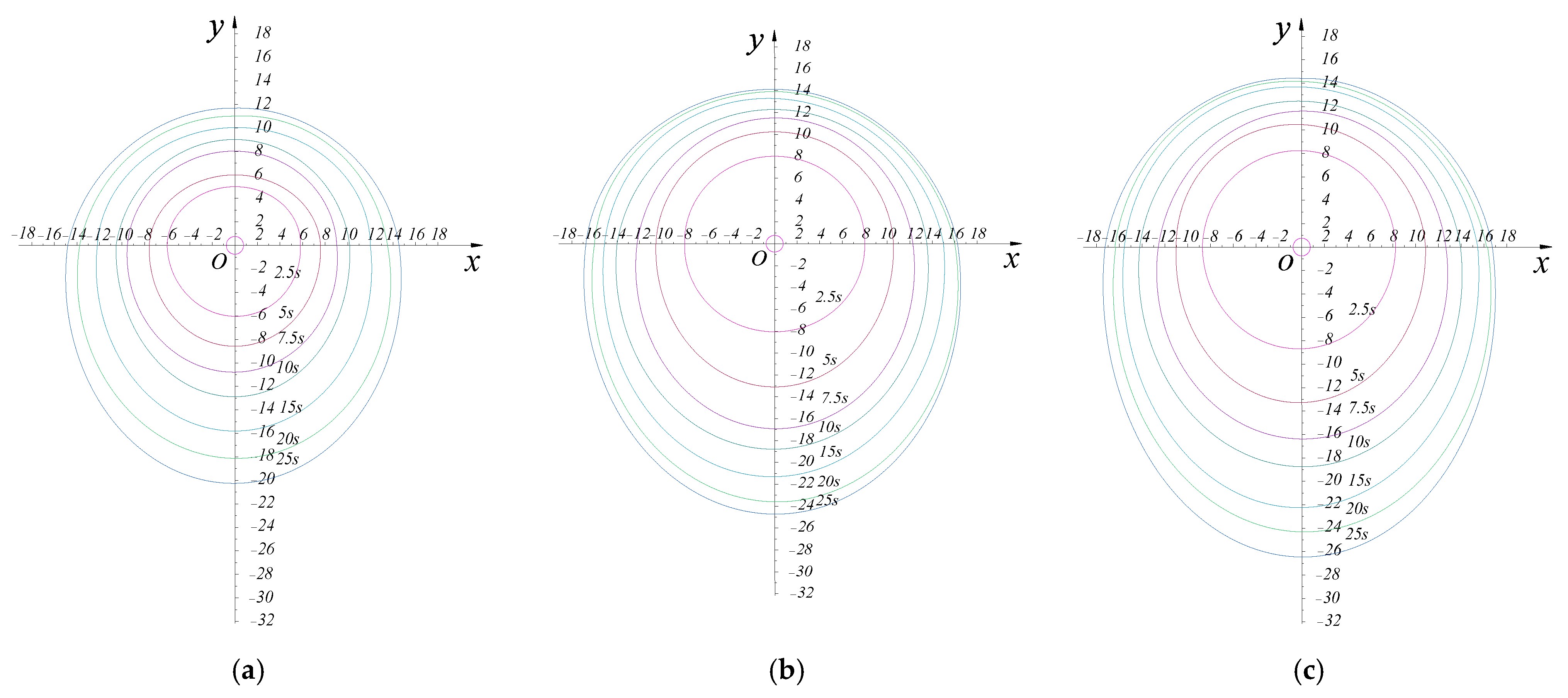
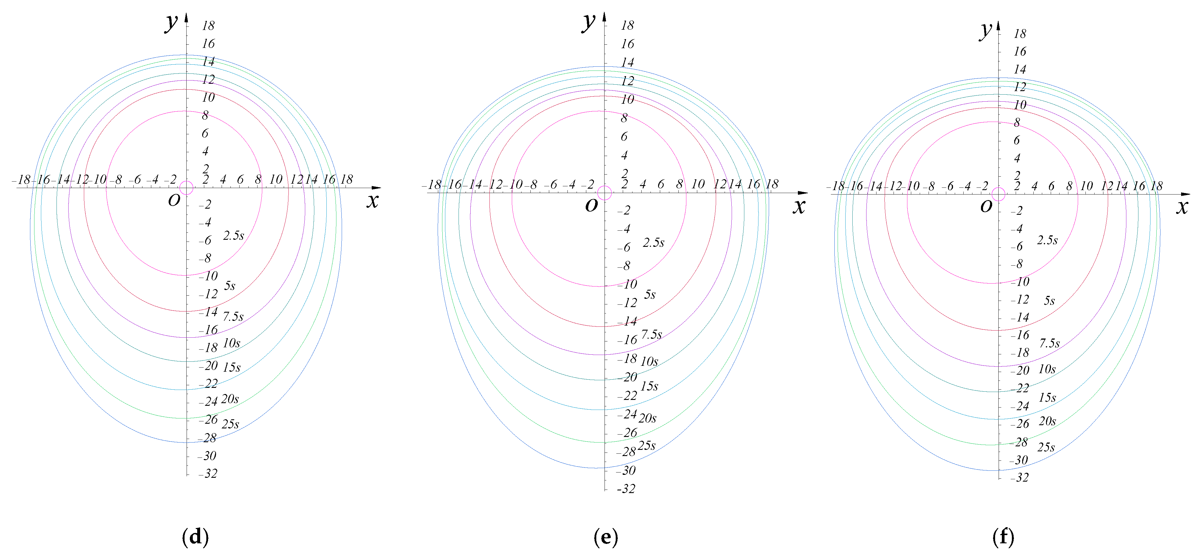
As the water–cement ratio increases from 0.5 to 1.0, the initial viscosity of the ultrafine cement slurry decreases from 33.6 mPa·s to 1.80 mPa·s. By changing the water–cement ratio of the cement grouting material, the initial viscosity parameters of the slurry have changed. Through the grouting test, it can be found that the diffusion of ultrafine cement slurry in cracks is mainly divided into three diffusion forms: circular diffusion zone, excessive diffusion zone, and elliptical diffusion zone. It is a circular diffusion zone within 0 to 2.5 s; 2.5 s to 5 s is the excessive diffusion zone; 5 s to 25 s is the elliptic diffusion zone. At the initial stage of grouting at 0 to 2.5 s, the slurry is not affected by self-weight, and the diffusion form is circular. After that, with the increase in time under the action of self-weight, the asymmetric elliptic characteristics of the diffusion form become more and more obvious, and the larger the water–cement ratio, the more obvious the overall diffusion asymmetry.
(2)
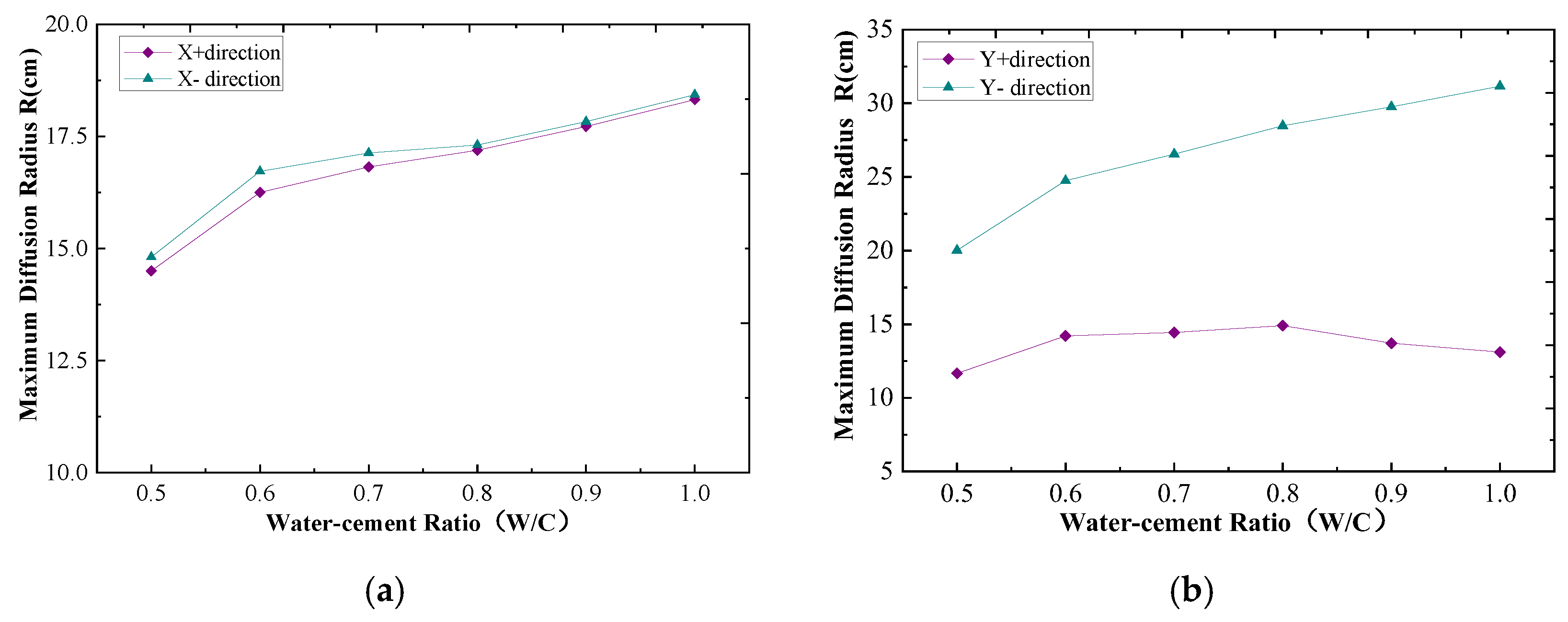
The analysis of the maximum diffusion radius can be seen in the y + direction of the maximum diffusion radius, but with the increase in the water–cement ratio, there is a tendency to increase and then decrease, which is subject to viscous stress, slurry pressure, and the common effect of self-weight, and there is a maximum diffusion radius of the water–cement ratio of the critical value of the diffusion radius through the analysis of the experimental data to obtain the diffusion radius of the extreme value of the critical water–cement ratio for ξ = 0.8.
(3)
The value of the maximum radius of diffusion R max increases with the water–cement ratio (W/C) (or is inversely proportional to the viscosity). As the water–cement ratio increases from 0.5 to 0.6, the maximum diffusion radius, R max , exhibits a significant increase. Within the water–cement ratio range of 0.6 to 1.0, the growth of R max becomes relatively stable. However, within the range of 0.8 to 1.0, the diffusion radius in the y+ direction is notably influenced by viscosity and gravitational effects, lead ing to a decreasing trend in R max .
(4)
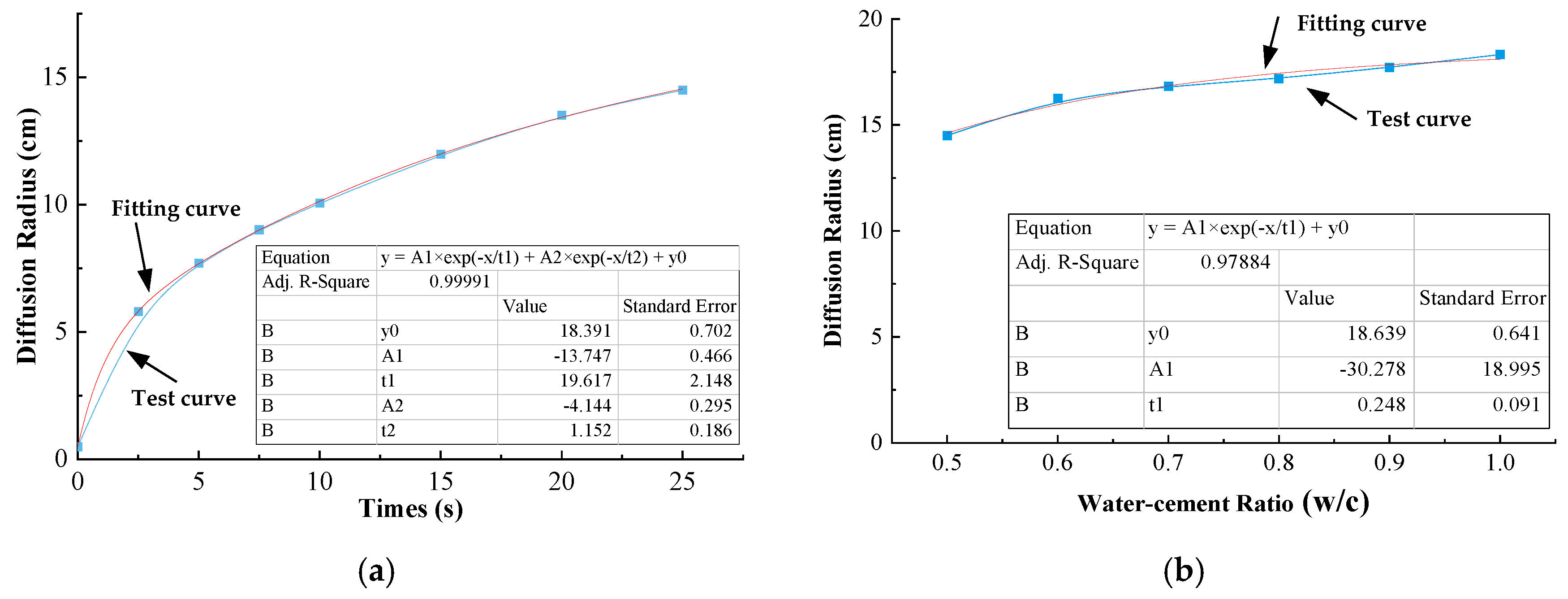
Through the collection and analysis of test data, the diffusion radius R and time t change function equation is obtained as R ( t ) = D 1   + A 1 e t / α A 2 e t / β ; the maximum diffusion radius value of R max and the change in the water–cement ratio function equation is R ( ξ ) = D 2   + A 3 e ξ / λ . The next step is to study the diffusion law of oblique crack grouting. It is helpful to perfect the study of the grouting diffusion law of tunnel secondary lining cracks.

Author Contributions

Writing—original draft, B.Z. and Y.W.; Writing—review & editing, P.L., L.W., C.L., S.L. and Y.Z. All authors have read and agreed to the published version of the manuscript.

Funding

This work was supported by the China Postdoctoral Science Foundation (No. 2023MD734186), State Key Laboratory of Mountain Bridge and Tunnel Engineering (SKLBT-2110), the Natural Science Foundation of Chongqing (2024NSCQ-LZX0138/2023NSCQ-MSX0197), the Chongqing Municipal Education Commission Science and Technology Fund (No. KJZD-M202204001).

Institutional Review Board Statement

Not applicable.

Informed Consent Statement

Not applicable.

Data Availability Statement

The data presented in this study are available upon request from the corresponding author due to privacy restrictions.

Conflicts of Interest

Author Peng Liu was employed by the company Chongqing Underground Application Research Institute Co., Ltd. The remaining authors declare that the re-search was conducted in the absence of any commercial or financial relationships that could be construed as a potential conflict of interest.

References

  1. Hong, K.; Feng, H. Development Trends and Views of Highway Tunnels in China over the Past Decade. China J. Highw. Transp. 2020, 33, 62–76. (In Chinese) [Google Scholar]
  2. Ge, S.; Gao, W.; Wang, Y.; Xie, Y.; Chen, X.; Wang, S. Review on evaluation and treatment of traffic shield tunnel defects in China. Chin. Civil Eng. J. 2023, 56, 119–128. (In Chinese) [Google Scholar]
  3. Gong, X.; Guo, P. Prevention and Mitigation Methods for Water Leakage in Tunnels and Underground Structures. China J. Highw. Transp. 2021, 34, 1–30. (In Chinese) [Google Scholar]
  4. Du, X.; Li, Z.; Fang, H.; Li, B.; Zhao, X.; Zhai, K.; Xue, B.; Wang, S. A State-of-the-Art Review on the Study of the Diffusion Mechanism of Fissure Grouting. Appl. Sci. 2024, 14, 2540. [Google Scholar] [CrossRef]
  5. Luo, Y.; Chen, J. Research Status and Progress of Tunnel Frost Damage. J. Traffic Transp. Eng. 2019, 6, 297–309. [Google Scholar] [CrossRef]
  6. Zhou, H.; Zhang, Y.; Zhu, W.; Zhong, Q.; Huang, X. Optimisation of Synchronous Grouting Mix Ratio for Shield Tunnels. Appl. Sci. 2024, 14, 4098. [Google Scholar] [CrossRef]
  7. Ding, Y.; Zhang, X.; Zhang, B. Preliminary Study on Double Lining Support Design for Water Plugging of Highway Tunnel under High Water Pressure in Mountain Area Based on Limited Drainage. Appl. Sci. 2022, 12, 7905. [Google Scholar] [CrossRef]
  8. Wang, M.; Zhao, C.; Yang, S.; Xu, J. Optimizing Grouting Parameters to Control Ground Deformation in the Shield Tunneling. Buildings 2024, 14, 2799. [Google Scholar] [CrossRef]
  9. Zhang, D.; Ye, Z.; Chu, W.; Zhang, J.; Shao, H. Experimental study on the rehabilitation of a shield tunnel lining with excessive transverse deformation by lateral grouting. Tunn. Undergr. Space Technol. 2024, 148, 105748. [Google Scholar] [CrossRef]
  10. Han, X.; Ye, F.; Wang, Y.; Xia, Y. Predictive Maintenance Decision-making of Tunnel Lining Structure Based on Deterioration Reliability. China J. Highw. Transp. 2021, 34, 104–115. (In Chinese) [Google Scholar]
  11. Huang, H.; Zhang, D. Recent Progress on Refined Sensing and Control of Safety and Risk of Long-and Large-scale Tunnel Lining Structures. China J. Highw. Transp. 2020, 33, 46–61. (In Chinese) [Google Scholar]
  12. Jiang, P.; Zhang, Z.; Zheng, H.; Huang, J. Coupling analysis method of grouting construction with deformation response of adjacent existing tunnel. Tunn. Undergr. Space Technol. 2024, 15, 312–330. [Google Scholar] [CrossRef]
  13. Wang, H.; Huang, H.; Feng, Y.; Zhang, D. Characterization of Crack and Leakage Defects of Concrete Linings of Road Tunnels in China. ASCE-ASME J. Risk Uncertain. Eng. Syst. Part A Civ. Eng. 2018, 4, 04018041. [Google Scholar] [CrossRef]
  14. Zhang, W.; Wang, Y.; Zong, Z.; Zhou, X.; Lin, W. Reliability Analysis Methods in Tunnel Construction and Operation. J. Chongqing Jiaotong Univ. (Nat. Sci.) 2020, 39, 1–13. (In Chinese) [Google Scholar]
  15. Hu, Z.; Ding, H.; Lai, J.; Wang, H.; Wang, X.; He, S. The durability of shotcrete in cold region tunnel: A review. Constr. Build. Mater. 2018, 185, 670–683. [Google Scholar] [CrossRef]
  16. Zhang, B.; Zhou, Y.; Zhang, X.; Wang, Z.; Yang, W.; Ban, Y. Experimental Study on Grouting Diffusion Law of the Different Crack Widths in Tunnel Lining. KSCE J. Civ. Eng. 2023, 27, 1789–1799. [Google Scholar] [CrossRef]
  17. Zhang, S.; Liu, X.; Wang, E. Quantitative evaluation of the onset and evolution for the non-Darcy behavior of the partially filled rough fracture. Water Resour. Res. 2024, 60, e2023WR036494. [Google Scholar] [CrossRef]
  18. Jian, L.; Zhao, X.; Wu, J.; Yan, H.; Wan, Y.; Wang, S.; Zhang, C.; Long, R. Preparation, properties and grouting process simulation of cement-based grout for loose deposits. Constr. Build. Mater. 2022, 360, 129596. [Google Scholar] [CrossRef]
  19. Li, S.; Liu, R.; Zhang, Q.; Sun, Z.; Zhang, X.; Zhu, M. Research on C-S Slurry Diffusion Mechanism with Time-Dependent Behavior of Viscosity. Chin. J. Mech. Eng. 2013, 32, 2415–2421. (In Chinese) [Google Scholar]
  20. Liu, R.; Zhang, L.; Zhang, Q.; Yang, L.; Li, Z.; Sun, Z.; Zhang, S.; Zhu, G. Numerical Simulation of Crack Grouting Process of Quick Setting Slurry with Running Water and Its Experimental Verification. Rock Soil Mech. 2017, 36, 3297–3306. (In Chinese) [Google Scholar]
  21. Zhou, J.; Zha, L.; Meng, S.; Zhang, Y. Optimization on overall performance of Modified Ultrafine Cementitious Grout Materials (MUCG) and hydration mechanism analysis. PLoS ONE 2024, 19, e0309312. [Google Scholar] [CrossRef] [PubMed]
  22. Zhou, Z.; Du, X.; Wang, S.; Cai, X.; Chen, L. Micro mechanism of the diffusion of cement-based grouts in porous media under two hydraulic operating conditions: Constant flow rate and constant pressure. Acta Geotech. 2019, 14, 825–841. [Google Scholar] [CrossRef]
  23. Zhang, L.; Zhang, Q.; Liu, R.; Li, S. Grouting Mechanism in Fractured Rock Considering Slurry-rock Stress Coupling Effects. Chin. J. Geotech. Eng. 2018, 40, 2003–2011. (In Chinese) [Google Scholar]
  24. Fu, N.H.J.; Thorn, J. Radial Penetration of Cementitious Grout Laboratory Verification of Grout Spread in a Fracture Model. Tunn. Undergr. Space Technol. 2018, 72, 228–232. [Google Scholar] [CrossRef]
  25. Wang, X.; Li, L.; Mu, W.; Yang, T.; An, J.; Du, Y. Diffusion mechanism of cement-based slurry in frozen and thawed fractured rock mass in alpine region. Constr. Build. Mater. 2024, 411, 134584. [Google Scholar] [CrossRef]
  26. Luo, P.; Li, Z.; Fan, B.; Zhang, Y. Theoretical Study on Flow Model for Tilted Single Fracture Bingham Grouts. J. Shandong Univ. Sci. Technol. (Nat. Sci.) 2010, 29, 49–53. (In Chinese) [Google Scholar]
  27. Xu, X.; Wu, Z.; Weng, L.; Chu, Z.; Liu, Q.; Wang, Z. Investigating the impacts of reinforcement range and grouting timing on grouting reinforcement effectiveness for tunnels in fault rupture zones using a numerical manifold method. Eng. Geol. 2024, 330, 107423. [Google Scholar] [CrossRef]
  28. Zhou, M.; Li, S.; Zheng, Z.; Liu, R.; Chen, M.; Ma, C. Theoretical and experimental study on the rheological properties of WIS grout and the dispersion and sealing mechanism. Int. J. Min. Sci. Technol. 2022, 32, 669–684. [Google Scholar] [CrossRef]
  29. Li, X.; Wang, L.; Hao, M.; Zhong, Y.; Zhang, B. An Analytical Solution for the Radial Flow of Variable Density Grout in Rock Fractures. Constr. Build. Mater. 2019, 206, 630–640. [Google Scholar] [CrossRef]
  30. Wu, Y.; Deng, Y.; Zhang, X.; Liu, L.; Zhao, C.; Zhang, J. Grout Diffusion Mechanism along the Pile Shaft during the Process of Pile Tip Post-Grouting in Sand. Appl. Sci. 2024, 14, 5389. [Google Scholar] [CrossRef]
  31. Hao, Y.; Guo, C.; Shi, M.; Wang, F.; Xia, Y.; Wang, C. Application of polymer split grouting technology in earthen dam: Diffusion law and applicability. Constr. Build. Mater. 2023, 369, 130612. [Google Scholar] [CrossRef]
  32. Xu, B.; Zhang, H.; Yin, J.; Xue, Y. Infiltration Grouting Mechanism of Bingham Fluids in Porous Media with Different Particle Size Distributions. Appl. Sci. 2023, 13, 11986. [Google Scholar] [CrossRef]
  33. Jiang, D.; Cheng, X.; Luan, H.; Wang, T.; Zhang, M.; Hao, R. Experimental Investigation on the Law of Grout Diffusion in Fractured Porous Rock Mass and Its Application. Processes 2018, 6, 191–201. [Google Scholar] [CrossRef]
  34. Hu, H.-X.; Cao, W.; Deng, C.; Lu, Y.-F. Experimental Study on the Relationship between Time-Varying Uplift Displacement and Grout Diffusion in Sand. Appl. Sci. 2024, 14, 3922. [Google Scholar] [CrossRef]
  35. Zhang, B.; Gao, F.; Zhang, X.; Zhou, Y.; Hu, B.; Song, H. Study on Modified Cement-Sodium Silicate Material and Grouting Technology for Repairing Underground Concrete Structure Cracks. Arab. J. Geosci. 2019, 12, 680. [Google Scholar] [CrossRef]
Figure 1. Grouting materials and slurry diffusion pattern: (a) Four kinds of additive materials; (b) mixing device; (c) slurry morphology diagram.
Applsci 15 01955 g001
Figure 2. Rheological curve of slurry with different water cement ratio. (a) The variation curve of shear stress with shear rate; (b) the change curve of viscosity with shear rate.
Applsci 15 01955 g002
Figure 3. Secondary lining crack grouting model: (a) crack side view; (b) model crack plane front view.
Applsci 15 01955 g003
Figure 4. Slurry diffusion patterns in different water–cement ratios: (a) ξ = 0 .5 viscosity 33.6 mPa·s; (b) ξ = 0 .6 viscosity 20.2 mPa·s; (c) ξ = 0 .7 viscosity 6.3 mPa·s; (d)   ξ = 0 .8 viscosity 3.2 mPa·s; (e) ξ = 0 .9 viscosity 2.5 mPa·s; (f) ξ = 1 .0 viscosity 1.8 mPa·s.
Applsci 15 01955 g004aApplsci 15 01955 g004b
Figure 5. Time history curves of diffusion radius in different water–cement ratio: (a) x+ direction; (b) x− direction; (c) y+ direction; (d) y− direction.
Applsci 15 01955 g005
Figure 6. Maximum diffusion radius in different water–cement ratios: (a) horizontal direction; (b) vertical direction.
Applsci 15 01955 g006
Figure 7. Maximum diffusion radius in different water–cement ratio: (a) R~t variation relation; (b) R~ξ variation relation.
Applsci 15 01955 g007
Table 1. Material mix ratio.
MaterialUltrafine CementUltrafine Fly AshExpansive AgentEarly Strength Agent
Particle Size/Grade/Type≤8 μm, D50
≤18 μm, D90
HSDZ-60MNF-9
Mass Ratio75%20%3%2%
Table 2. Grouting parameters.
Crack Width
δ
Water–Cement Ratio
W/C
Initial Grouting Pressure
P0
Fracture Plane Dip Angle
θ
Grouting Port Speed
u -
0.4 mm0.5~1.00.05 MPa90°5 mL/s
Table 3. Initial viscosity of slurry at different water–cement ratio.
W/C0.50.60.70.80.91.0
Initial Viscosity η (mPa·s)33.6220.206.263.242.531.80
Table 4. Test value of grouting diffusion radius in different water–cement ratio.
Diffusion
Radius R (cm)
Time Water Cement   Ratio   w / c = ξ
0.50.60.70.80.91.0
Direction x+00.500.500.500.500.500.50
2.55.818.028.228.718.929.12
5.07.7110.4810.9511.5712.0112.51
7.59.0212.2112.6213.2213.7314.59
10.010.0713.5513.9614.3414.9815.98
15.011.9815.0115.4115.7616.5517.35
20.013.5216.0116.3716.8517.4318.03
25.014.5016.2516.8217.1917.7218.32
Direction x−0−0.50−0.50−0.50−0.50−0.50−0.50
2.5−6.02−8.03−8.70−9.15−9.95−10.45
5.0−7.77−10.52−11.02−11.52−12.43−13.13
7.5−9.53−12.23−12.53−13.21−14.35−14.95
10.0−10.55−13.98−14.18−14.58−15.63−16.12
15.0−12.22−15.12−15.62−16.21−17.06−17.46
20.0−13.79−16.03−16.49−16.97−17.45−17.95
25.0−14.81−16.72−17.13−17.31−17.83−18.43
Direction y+00.500.500.500.500.500.50
2.55.038.018.218.888.818.21
5.06.8510.2210.5210.9710.229.85
7.58.0811.5211.6211.9411.1610.56
10.08.9512.2312.5312.8011.7411.33
15.010.0613.3513.6513.8412.7312.24
20.011.0213.8914.1014.5613.3412.79
25.011.6614.2114.4414.9113.7113.11
Direction y−0−0.50−0.50−0.50−0.50−0.50−0.50
2.5−6.05−8.12−8.71−9.86−10.05−10.05
5.0−8.55−13.01−13.31−13.84−14.38−15.38
7.5−10.75−15.86−16.36−16.76−17.43−19.43
10.0−12.89−18.75−18.58−19.44−20.18−22.18
15.0−15.88−21.30−22.33−22.59−23.41−25.41
20.0−18.12−23.62−24.42−25.74−26.68−28.18
25.0−20.02−24.75−26.55−28.48−29.76−31.16
Table 5. Parameter Values of grouting diffusion equation in different water–cement ratio.
Equation R ( t ) =   D 1   + A 1 e t α A 2 e t β R ( ξ ) =   D 2   + A 3 e ξ λ
Direction D 1 A 1 α A 2 β Correlation Coefficient D 2 A 3 γ Correlation Coefficient
x+18.39−13.7519.62−4.141.15118.64−30.280.250.98
x−−17.594.001.0413.0916.271−18.3451.550.180.96
y+12.78−3.811.59−8.4812.7310.08314.760.700.91
y−−30.1224.9827.315.032.231−32.8280.380.270.99
Disclaimer/Publisher’s Note: The statements, opinions and data contained in all publications are solely those of the individual author(s) and contributor(s) and not of MDPI and/or the editor(s). MDPI and/or the editor(s) disclaim responsibility for any injury to people or property resulting from any ideas, methods, instructions or products referred to in the content.

