Article

Calculation Method for Settlement Deformation of Existing Tunnel Induced by Underpass Construction

1
School of Civil Engineering, Central South University, Changsha 410075, China
2
National Engineering Research Center of High-Speed Railway Construction Technology, Central South University, Changsha 410075, China
*
Author to whom correspondence should be addressed.
Appl. Sci. 2025, 15(5), 2430; https://doi.org/10.3390/app15052430
Submission received: 22 January 2025 / Revised: 21 February 2025 / Accepted: 22 February 2025 / Published: 24 February 2025
(This article belongs to the Special Issue Advanced Geomaterials and Reinforced Structures (Second Edition))

Abstract

:
To explore the calculation method of settlement and deformation of existing tunnels induced by excavation, the energy method is adopted to analyze the work done by the existing tunnels with additional loads during excavation and the additional stresses caused by shield cutter thrust, shield shell, etc. The study integrates Mindlin’s stress solution and three-dimensional Loganathan’s formula to determine the friction, grouting pressure, and stratum loss. The primary objective of this approach is to identify the settlement and deformation of the existing tunnel. It is envisaged that the deformation of tunnels can be resolved by minimizing the total potential energy of the system. Relying on a new construction project, part of the Macao Sewerage Pipeline, the reasonableness and accuracy of theoretical model are verified by comparing it with the results of on-site monitoring and numerical analysis. Meanwhile, parameter sensitivity analysis is carried out to determine the sensitivity factors, including tunnel depth, diameter, and ground loss rate, on the settlement of existing tunnel, and suggestions for optimization on project are provided. The findings demonstrate the efficacy of the theoretical method in predicting the settlement and deformation of existing tunnels. Furthermore, it is evident that it can mitigate the settlement of existing tunnels by increasing the depth of new tunnels. Additionally, expanding the diameter of excavation is also a significant factor. Conversely, an increase in excavation rate will lead to an enhancement in the loss of ground layer, thereby augmenting the settlement of existing tunnels. It is noteworthy that the diameter of excavation exerts the most substantial influence on the settlement, followed by the rate of loss of ground layer, and to a lesser extent, the depth of the buried tunnel.

1. Introduction

An extensive use of subterranean areas has become a significant component of the development and construction of many cities. Existing tunnels will inevitably be penetrated by new ones as urban underground space is developed and used. The construction of a new tunnel intersecting an existing one frequently entails complex interactions between them, resulting in intricate mechanical properties. Many scholars have carried out relevant studies on such complex working conditions [1,2,3,4,5,6]. Gan et al. [7] performed extensive on-site monitoring on the Hangzhou Metro Line 2 subway passage project and discovered that the existing tunnel experienced a bulging due to buoyancy when the shield tail traversed it. The location of the bulge was influenced by the angle between two tunnels. Augmenting the gap between the tunnels and enhancing the grouting elements could substantially mitigate the bulging effect. By a series of centrifuge modeling experiments, Weng et al. [8] explored how the excavation sequence and the spacing between old and new tunnels affected the mechanical behavior of existing tunnels. They also investigated the influence of excavation sequences on the settlement of existing tunnels. Shi et al. [9] simulated the tunnel building process and suggested that the tunnel underpassing might affect the existing station’s safety following groundwater leaking. Lai et al. [10] investigated how different parameters affected the construction of tunnels. They used numerical simulation to alter construction factors (such as pressure) and work out the optimal range of parameters. The majority of the aforementioned researchers adopted numerical modelling and field surveillance techniques, but the on-site monitoring results were easily affected by construction factors and the surrounding environment, while the numerical simulation was time-consuming and the calculation results were not easy to converge.
In theory, the existing tunnel was hypothesized to be an elastic foundation beam, and researchers proposed a transfer of additional load from the new tunnel to the old tunnel, employing a two-stage approach. Xu et al. [11] used the local layer method to view the tunnel surrounding rock as a homogeneous stratum, considered the elliptical non-uniform convergence mode, and derived an improved random medium theoretical solution. Liang et al. [12] examined the mechanical response of an existing tunnel, modeled as an elastic beam supported on a Winkler foundation, when a new tunnel was constructed beneath it. Using the Winkler model’s superposition approach, Liu et al. [13] examined how the new tunnel would affect the existing tunnel’s bending moment and deflection in the no-gap scenario. Gan et al. [14] developed a calculation method for assessing the longitudinal deformation of existing tunnels when subjected to underpassing construction. This method was based on the Pasternak foundation model and the Loganathan solution, with ground loss changes being a key factor considered in the formulation. Zhang et al. [15] used the Kerr foundation model and proposed a theoretical solution considering the effect of ring-seam joints in existing tunnels and parametrically analyzed the equivalent flexural and shear stiffnesses of the existing tunnels. The finite difference method and eigenvalue method are usually adopted in previous studies, which require matrix transformation and integral construction of the control equations, resulting in a very complicated solution process. In contrast, the potential energy control equation is established through the functional relationship, and scholars have employed the energy technique to tackle tunnel deformation because of its simplicity and great computational accuracy. Liu et al. [16] proposed the solution of vertical displacement of a tunnel crossing underground pipeline by establishing the control equation through the energy method. Wei et al. [17] derived the calculation formula of pipeline settlement caused by different double-circle shield excavation conditions based on the modified Peck’s formula and the energy variational method. The majority of the aforementioned research estimated the ground displacement caused by the excavation of new tunnels based on Loganathan’s formula and the random medium theory, which took into account the impact of soil loss on ground displacement. However, the influence of construction factors during the shield construction was ignored.
The research results have promoted the construction and development of the tunnel underpass project. However, the calculation results of settlement and deformation caused by tunnel underpassing are still empirical, and the theoretical method needs to be further expanded and verified. This study adopts the energy technique to determine the deformation of existing tunnels when a new tunnel underpasses it. To validate the approach, field experiments and computer simulations are conducted while taking soil loss into consideration. On this basis, the effects of new tunnel depth, new tunnel diameter, and strata loss rate on the settlement of the existing tunnel are analyzed.

2. Settlement Calculations for Existing Tunnels

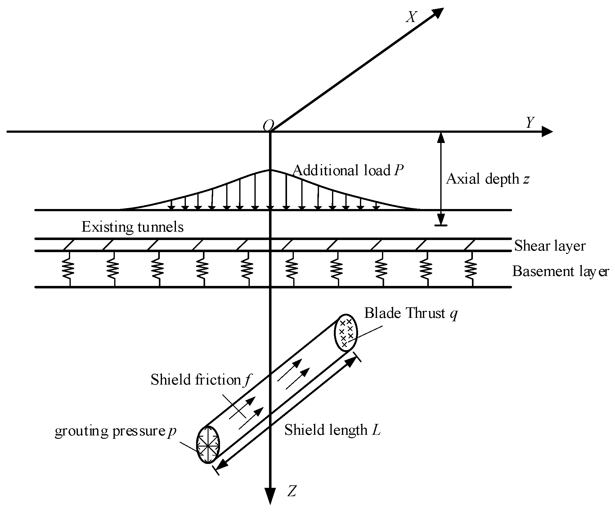
2.1. Model Assumptions

The existing tunnel will sink and distort as a result of the excavation of the new tunnel, which will put extra strain on the earth above it. In this study, considering the potential for additional loads and stratum loss, the existing tunnel is modeled as an elastic foundation beam. This approach forms the basis for developing a theoretical model to examine the settlement deformation of existing tunnels induced by tunnel penetration [18], as illustrated in Figure 1. The following assumptions are proposed to facilitate the calculation: (1) The existing tunnel is approximated as an Euler–Bernoulli beam, characterized by an equivalent longitudinal flexural rigidity (EI)eq; (2) The interaction between the tunnel and the surrounding soil is modeled using the Pasternak foundation approach; (3) The additional stresses in the strata are calculated by using Mindlin’s solution and the three-dimensional Loganathan’s formula; and (4) No consideration is given to the soil arch effect and drainage consolidation effect.

2.2. Energy Method

Because of its simplicity and comparatively high accuracy, the energy technique can rapidly forecast the settlement and deformation of existing tunnels. A sufficient displacement function must be assumed in order to use the energy technique to determine the influence of the excavation. The displacement function employed in this research is based on the Rayleigh–Ritz approach [16] and assumes that the vertical displacement pattern of the existing tunnel follows the normal distribution curve:
w = i = 0 n a i cos i π x L p = { C } 1 × ( n + 1 ) { a } ( n + 1 ) × 1
{ C } = 1 , cos π x L p , cos 2 π x L p , , cos n π x L p
{ a } = { a 0 , a 1 , a 2 , , a n } T
where: w is the existing tunnel’s vertical displacement; a is the coefficient to be determined; n is the order of the stiffness matrix in the subsequent calculations; Lp is the half-width of the existing tunnel’s settlement slot, which results from tunnel excavation; and x is the distance along the tunnel’s axis.
Generally speaking, the system’s total potential energy may be separated into three components [19]: the work performed by the foundation reaction force, the additional load brought on by the new tunnel’s excavation, and the bending strain energy of the existing tunnel. They can be expressed, respectively, as:
E 1 = 1 2 L p L p ( E I ) eq ( 2 w x 2 ) d x
E 2 = D 2 L p L p k w 2 d x + D 2 L p L p G ( w x ) 2 d x
E 3 = L p L p P w d x
where: (EI)eq is the existing tunnel’s equivalent bending stiffness; D is its diameter; k is the foundation’s reaction force coefficient; G is the foundation’s shear layer coefficient; P is the additional load, P = D σ z ; and σ z is the additional stress.
The foundation reaction force coefficient can be obtained through the following formula, which takes into account the impact of the existing tunnel’s depth [20]:
k = 3.08 E η ( 1 ν 2 ) E D 4 ( E I ) eq 8
η = 2.18 z / D 0.5 1 + 1 1.7 z / D z / D > 0.5
where E represents the soil’s modulus of elasticity; v is Poisson’s ratio; and z is the tunnel’s axial depth.
The Pasternak foundation model takes into account how the existing tunnel body interacts with the strata. The following formula, when combined with Xu’s study findings [21], may be used to determine the shear layer coefficient G on the Pasternak foundation:
G = 2.5 D E 6 ( 1 + v )
The new tunnel is built based on the principle of minimum potential energy. This means that the total energy of the existing tunnel is increased significantly, depending on each unknown factor. This total energy includes the bending strain energy of the existing tunnel, the work performed by the foundation reaction force, and the work done by the additional load resulting from the tunnel excavation.
L p L p E I eq 2 w / x 2 a i 2 C x 2 d x + D L p L p k w a i C a d x + D L p L p G ( w / x ) a i { C } x { a } d x = L p L p { P } { C } d x
Associative Equations (1)–(3) and Equation (10) allow the partial differential results to be expressed in matrix form:
[ K 1 ] + [ K 2 ] { a } = { P }
[ K 1 ] = ( E I ) eq π 4 L p 3 0 1 2 4 n 4
[ K 2 ] = k D L p 2 1 1 1 + G D π 2 L p 0 1 2 2 n 2
From this, we can calculate { a } , which can then be substituted into Equation (1) to obtain the vertical displacement w of the existing tunnel caused by the new tunnel excavation. This process is calculated by programming, and the order of the stiffness matrix is taken as n = 10th order.

3. Calculation of Additional Stresses in Tunnel Undercutting

The work performed by the increased load brought on by the new tunnel’s excavation is a crucial component of the formula derivation in the energy calculation technique. Under the condition of underpassing construction, the shield machine has a complex interaction relationship with the surrounding soil, thus inducing additional stresses in the existing tunnel. The following four primary components [22] can be taken into account when analyzing the extra stresses created during the building process: (a) soil loss; (b) shield shell friction f; (c) grouting pressure p; and (d) shield cutter thrust q. Therefore, the additional stresses due to these four factors need to be derived separately.

3.1. Mindlin’s Solution for Additional Stresses

Mindlin [23] proposed a theoretical analytical formulation for the distribution of displacements and stresses in a semi-infinite space subjected to a concentrated force, as shown in Figure 2. When vertical concentrated force P1 and horizontal concentrated force P2 act on an internal point (0, 0, c) in semi-infinite space, the Mindlin stress solution at any point (x, y, z) is expressed as follows:
d σ z = P 1 8 π ( 1 ν ) ( 1 2 ν ) ( z c ) R 1 3 3 z 3 4 ν z + c 2 3 c z + c 5 z c R 2 5 + ( 1 2 ν ) ( z c ) R 2 3 3 ( z c ) 3 R 1 5 30 c z z + c 3 R 2 7
d σ z = P 2 x 8 π ( 1 ν ) 1 2 ν R 1 3 1 2 ν R 2 3 3 ( z c ) 2 R 1 5 3 ( 3 4 ν ) ( z + c ) 2 R 2 5 + 6 c R 2 5 c + ( 1 2 ν ) ( z + c ) + 5 z z + c 2 R 2 2
Among them:
R 1 = x 2 + y 2 + z c 2
R 2 = x 2 + y 2 + z + c 2
where: P is the concentration force; μ is the Poisson’s ratio of the soil.

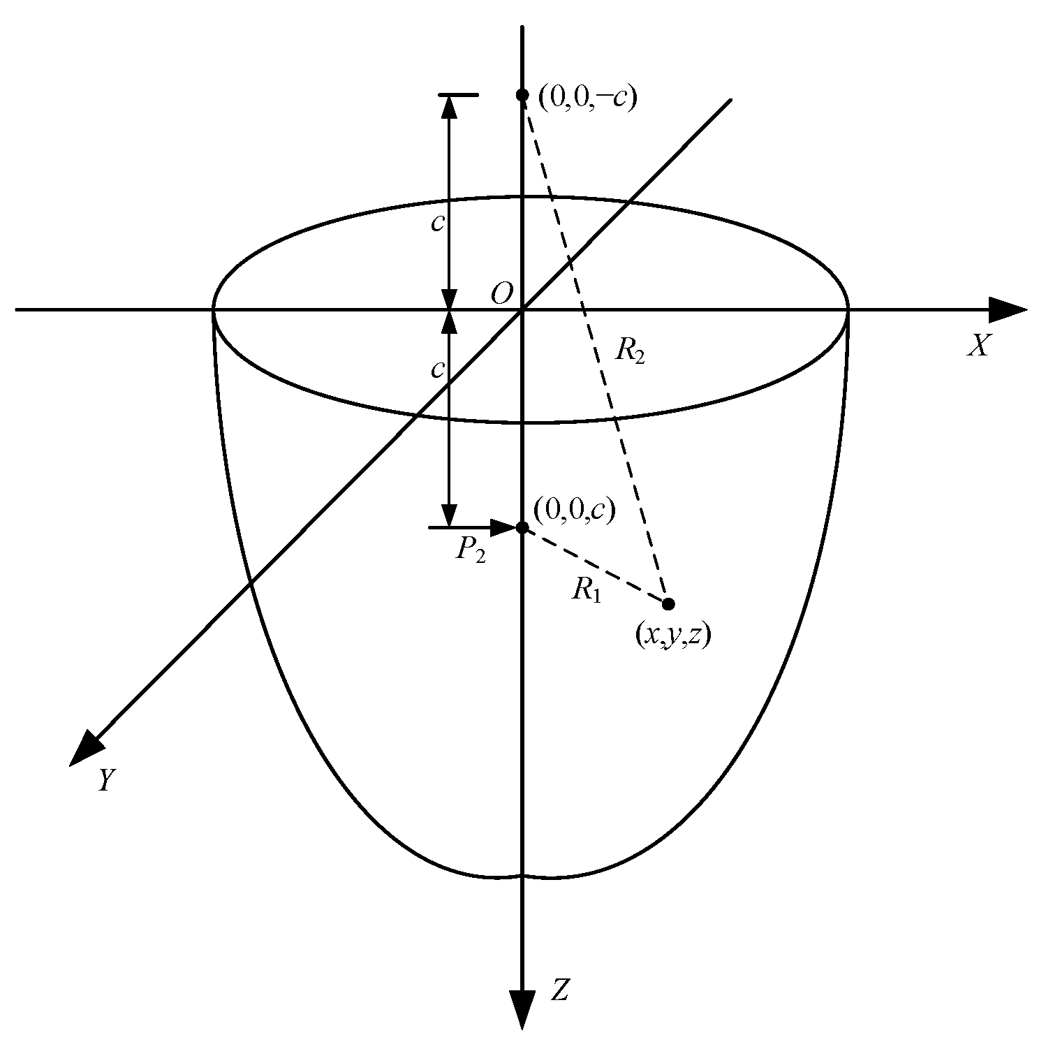
3.2. Additional Stresses Caused by Shield Cutter Thrusts

The tunnel shield cutter thrust will generate additional stresses on the soil layer. The cutter thrust is the support force needed to keep the excavation surface stable during shield construction. With reference to Wang et al.’s study findings [24], it may be computed using the formula below:
q = 10.13 1 ν E π ν 0 1 ξ 2 1 + ν 3 4 ν D m w + Δ q
where: Δ q is the squeezing force generated by the cutter disk cutting into the soil; E is the elastic modulus of the soil; v0 is the propulsion speed of the shield machine; w is the rotational speed of the cutter disk; ζ is the opening rate of the cutter disk; and m is the number of cutter disk chunks.
As seen in Figure 3, the circular surface containing the frontal thrust is integrated based on the Mindlin extra stress solution for the horizontal focused force. Let the center coordinates of the excavation surface be (0, 0, h) and the integral transformation equations are d s = r d θ d r , y = r c o s θ , and z = h r s i n θ , which give the coordinates of the homogeneous force microelement at any point on the circular surface as ( 0 , r c o s θ , h r s i n θ ) . The area division of the circle can be obtained:
σ q = 0 R 0 2 π q x 8 π ( 1 ν ) 1 2 ν R 3 3 1 2 ν R 4 3 3 ( 3 4 ν ) z + h r sin θ 2 R 4 5 3 z h + r sin θ 2 R 3 5 + 6 ( h r sin θ ) R 4 5 ( h r sin θ + ( 1 2 ν ) ( z + h r sin θ ) + 5 z z + h r sin θ 2 R 4 2 r d θ d r
Among them:
R 3 = x 2 + ( y r cos θ ) 2 + ( z h + r sin θ ) 2
R 4 = x 2 + ( y r cos θ ) 2 + ( z + h r sin θ ) 2
where σ q is the extra stress brought on by the cutter’s increased thrust; q is the cutter’s increased thrust; R is the shield machine’s radius; and h is the shield machine’s depth.

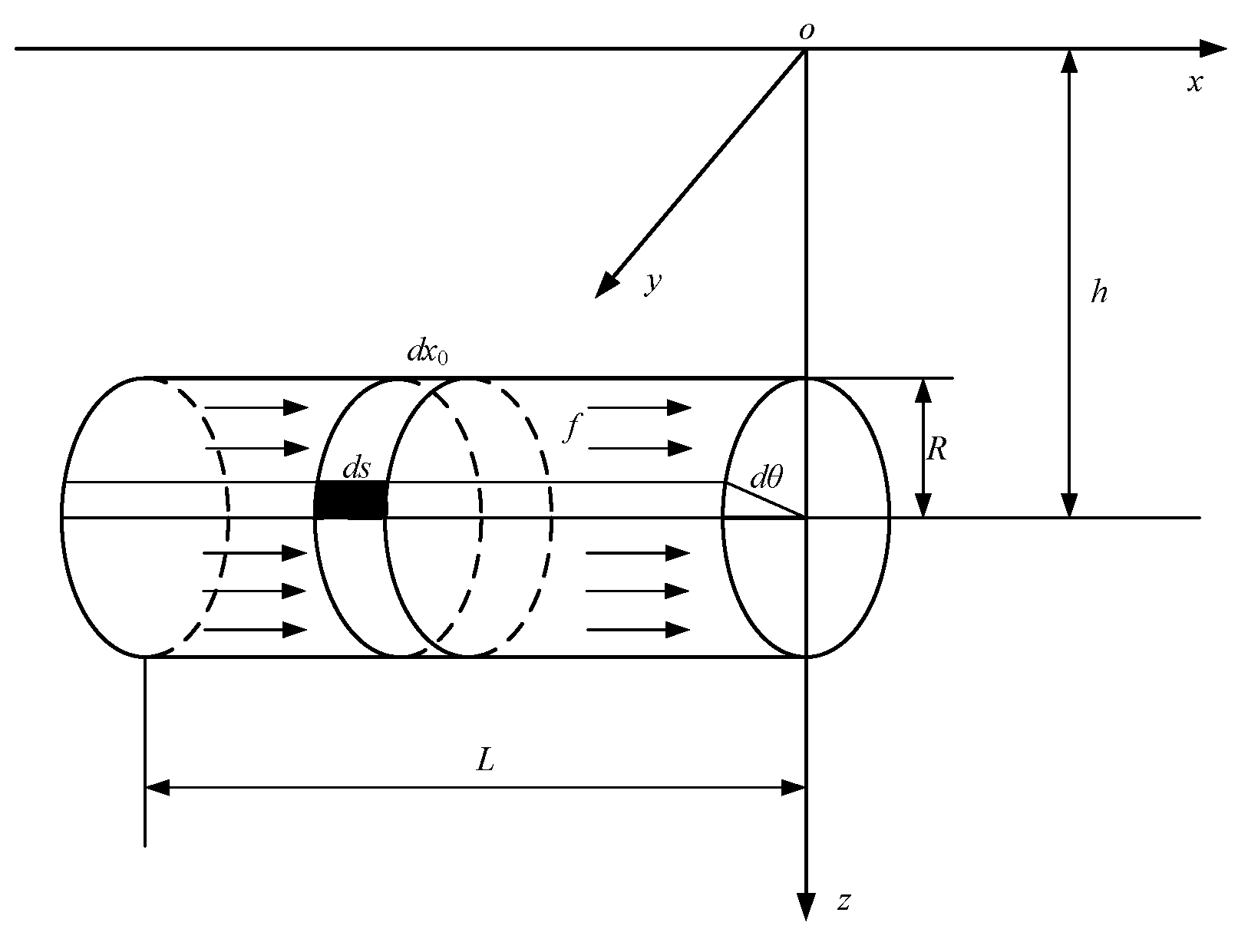
3.3. Additional Stress Caused by Shield Shell Friction

As seen in Figure 4, set the shield machine’s length to L and the excavation surface’s coordinates to (0, 0, h). The integral transformation equations are d s = R d θ d x 0 , y = R cos θ and z = h R sin θ , which are obtained by integrating along the cylindrical plane for the microelement coordinates x 0 , R cos θ , h R sin θ of the shield surface:
σ f = L 0 0 2 π f x x 0 8 π 1 ν 1 2 ν R 6 3 + 1 2 ν R 5 3 3 ( 3 4 ν ) z + h R sin θ 2 R 6 5 3 ( z h + R sin θ ) 2 R 5 5 + 6 ( h R sin θ ) R 6 5 ( h R sin θ + ( 1 2 ν ) ( z + h R sin θ ) + 5 z z + h R sin θ 2 R 6 2 R d θ d x 0
Among them:
R 5 = x x 0 2 + y R cos θ 2 + z h + R sin θ 2
R 6 = x x 0 2 + y R cos θ 2 + z + h R sin θ 2
where: σ f is the additional stress caused by shield shell friction; f is the friction; L is the shield’s length.
The following simple equation is used to compute the shield shell friction [25]:
f = K W π D + f ν + f h 2
f ν = γ h
f h = γ ( h + D / 2 ) tan 2 ( π 4 φ 2 )
where: r is the soil’s weight; φ is the friction angle within the soil; W is the shield machine’s self-weight per unit length; and K is the friction factor between the shield shell and the soil.

3.4. Additional Stress Caused by Grouting Pressure

Suppose the pressure at the tail is p, and its effective range corresponds to the length of a ring of segments, denoted as Lg. Consider the center coordinates of the excavation face of the shield machine to be (0, 0, h). For the surface of the shield machine, define the coordinates of a microelement as x 0 , R cos θ , h R sin θ . The grouting pressure p is then decomposed into horizontal ph and vertical pv components [26]. By integrating over the length range of the shield machine, the following results are obtained:
σ p h = L L g L o 2 π p ( y R cos θ ) 8 π ( 1 ν ) 1 2 ν R 7 3 1 2 ν R 8 3 3 ( 3 4 ν ) z + h R sin θ 2 R 8 5 3 z h + R sin θ 2 R 7 5 + 6 ( h R sin θ ) R 8 5 ( h R sin θ + ( 1 2 ν ) ( z + h R sin θ ) + 5 z z + h R sin θ 2 R 8 2 R cos θ d θ d x 0
σ p ν = L L g L 0 2 π p 8 π ( 1 ν ) 3 z h + R sin θ 3 R 7 5 + ( 1 2 ν ) ( z h + R sin θ ) R 8 3 ( 1 2 ν ) ( z h + R sin θ ) R 7 3 1 R 8 5 [ 3 z ( 3 4 ν ) ( z + h R sin θ ) 2 + 3 ( h R sin θ ) ( z + h R sin θ ) 5 z h + R sin θ 30 h R sin θ z z + h R sin θ 3 R 8 7 R sin θ d θ d x 0
Among them:
R 7 = x x 0 2 + y R cos θ 2 + z h + R sin θ 2
R 8 = x x 0 2 + y R cos θ 2 + z + h R sin θ 2
where: Lg is the width of a ring of pipe sheets; p is the synchronized grouting pressure; σ p h , σ p ν is the extra stress brought on by the grouting pressure’s horizontal and vertical components.

3.5. Additional Stresses due to Strata Loss

Considering the three-dimensional space as a composition of countless two-dimensional planes, the analytical solution for the three-dimensional soil displacement due to strata loss can be derived by combining the Sagaseta mirroring method on the basis of Loganathan’s two-dimensional solution [27]:
w z = η R 2 2 h z y 2 + h z 2 + 3 4 ν h + z y 2 + h + z 2 2 z y 2 h + z 2 y 2 + h + z 2 2 1 x x 2 + y 2 + h 2 exp 1.38 y 2 h + R 2 0.69 z 2 h 2
where: η is the strata loss rate.
The additional load can be solved by ground deformation [28], which is calculated as follows:
σ s = k w z G d 2 w z d x 2
In conclusion, the total increased vertical tension along the existing tunnel’s axis as a result of tunnel penetration is determined by:
σ z = σ q + σ f + σ p + σ s

3.6. Calculation Flow Chart

Figure 5 illustrates the settlement and deformation calculation procedure of the existing tunnel brought on by the new tunnel underpass based on the above theory.

4. Engineering Case Comparison

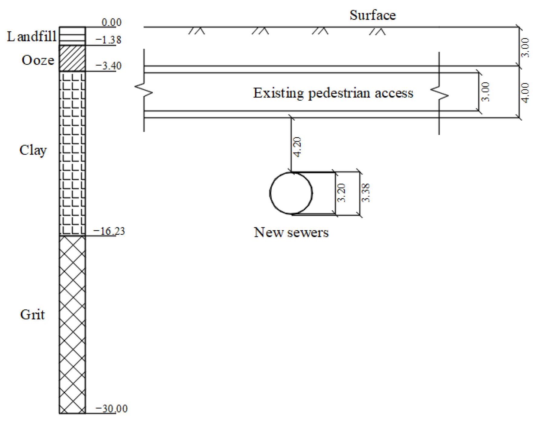
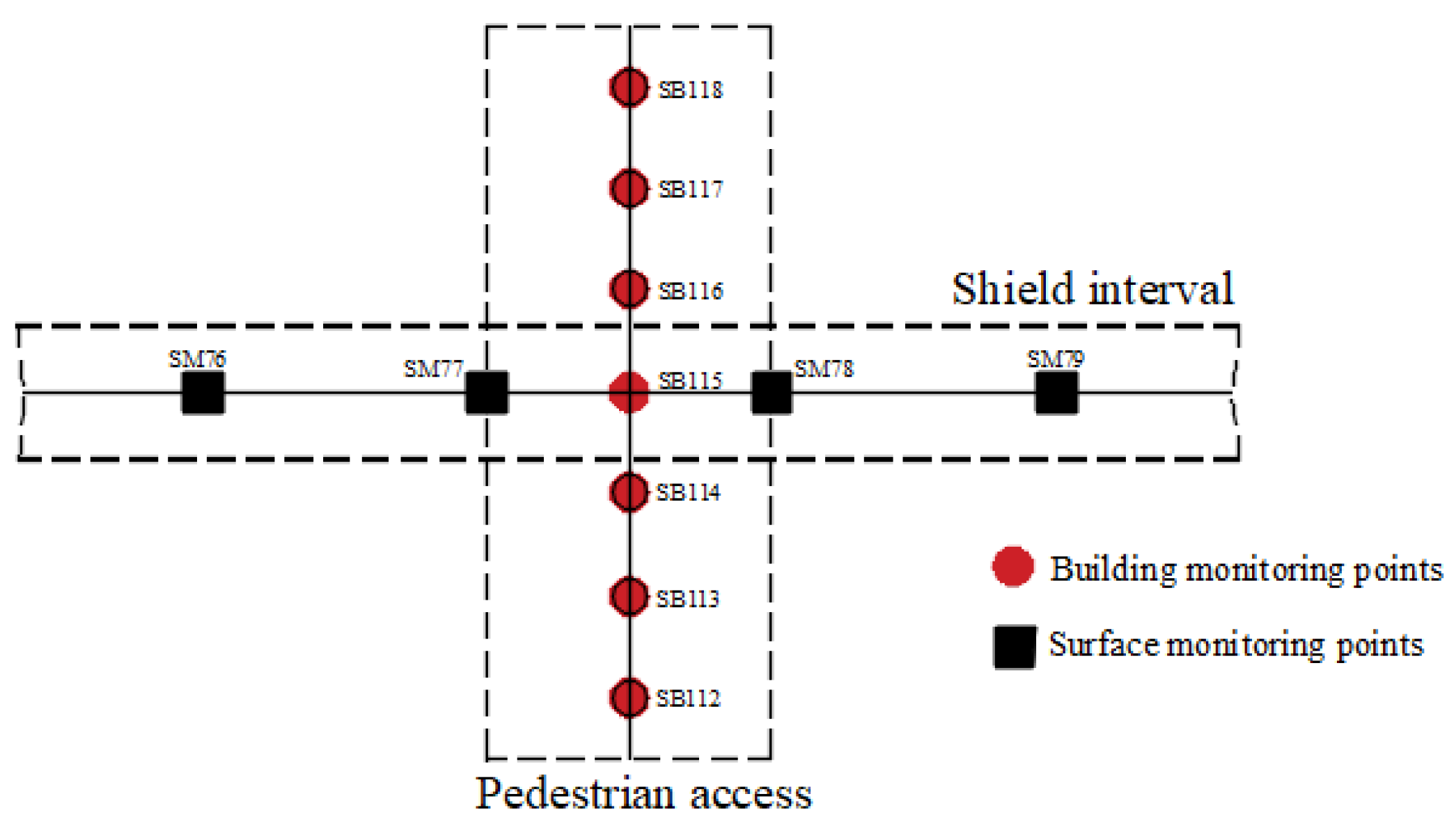
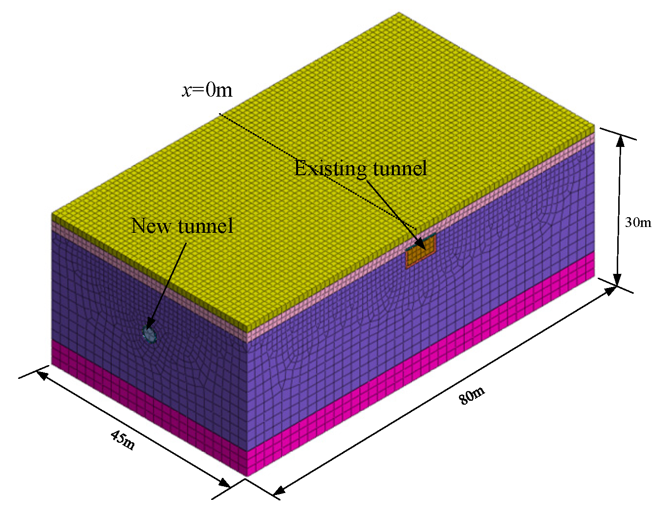
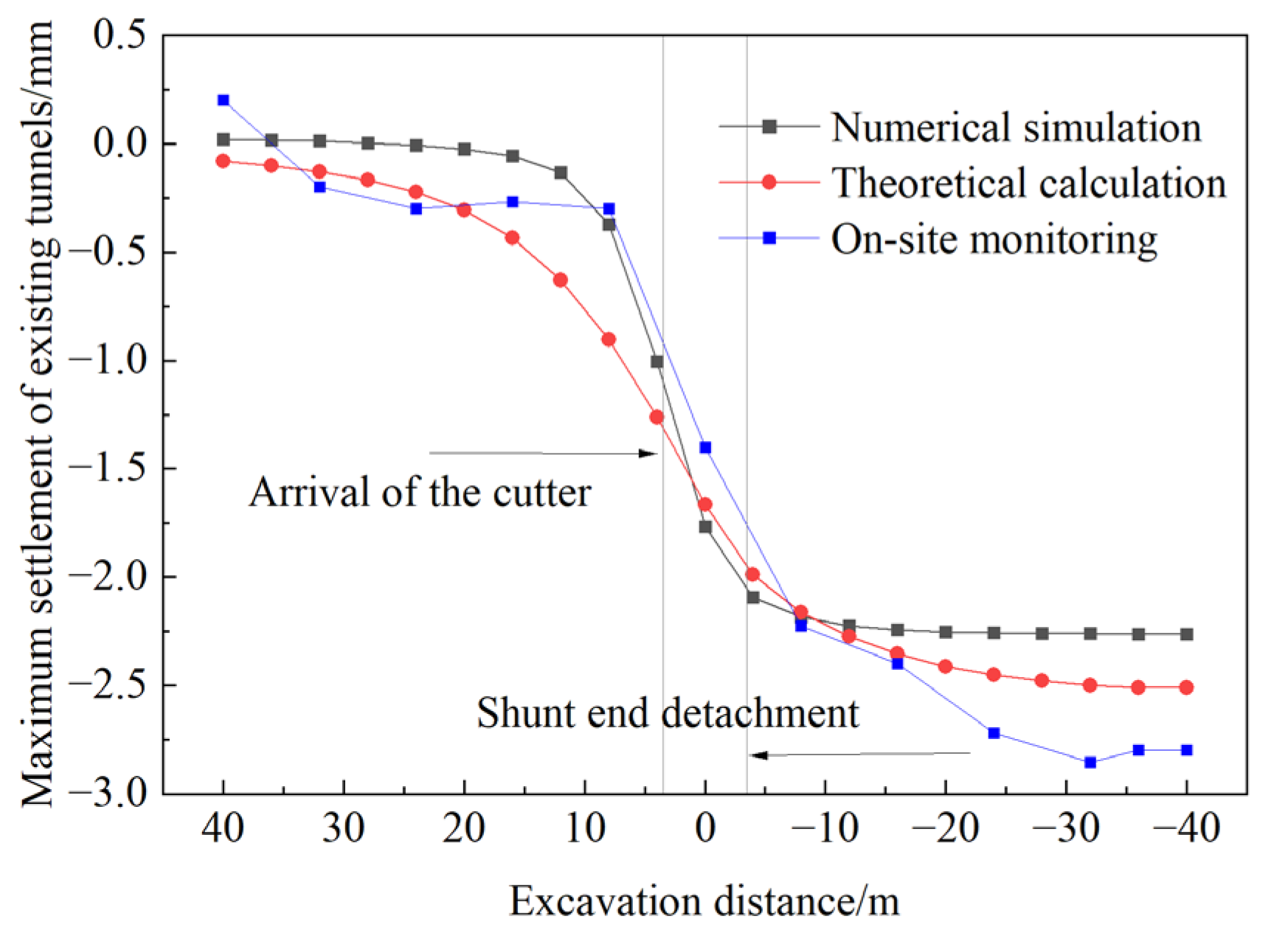
4.1. Engineering Measurements and Numerical Simulations

Macau new port area sewage pipe new construction project: shield machine for the soil pressure balance shield machine, body length of 7.8 m, excavation radius of 3.38 m, pipe sheet width of 1 m, shield machine opening rate ξ = 38%, the number of cutter plate chunks m = 6, the mass of about 240 t. The tunnel under the Lotus Square pedestrian tunnel is the object of study. Figure 6 illustrates the relative positional relationship between the two tunnels as well as the distribution of the strata in the area. The existing pedestrian tunnel is a single-width box culvert beneath the tunnel, with a cross-section size of 7 × 4 m, a top plate depth of 3 m, and a clear distance of 4.2 m between the top of the new tunnel and the bottom plate of the tunnel.
The shield tunnel mostly travels through the layer of powdery clay. The following characteristics are taken into consideration: the soil layer’s average heaviness is 19.5 kN/m3, its average elastic modulus E is 23.1 MPa, its Poisson’s ratio is 0.3, and its angle of internal friction is 27.5°. According to the parameters of the engineering case and the relevant formula above, the cutter plate thrust is 80 kPa, the friction force is 62 kPa, the synchronous grouting pressure is 0.15 MPa, the soil loss rate is 0.48%, and the equivalent bending stiffness (EI)eq = 7.786 × 10⁷ kN∙m2.
As illustrated in Figure 7, standard monitoring points were positioned in the ground surface and the passage structure in accordance with the relative positions of two tunnels in order to comprehend the ground and pedestrian passage deformation data over time and to gather dynamic information pertaining to the shield construction. Seven building settlement monitoring points are positioned along the longitudinal direction of the passageway at the axial line, numbered SB112~SB118 from bottom to top, and four surface settlement monitoring points, numbered SM76~SM79, are positioned along the shield tunneling direction. On-site monitoring is carried out by total station for fourth-class level measurement with a monitoring accuracy of 1 mm, and the monitoring frequency is 2 times/day within 20 m before and after the arrival of the shield and 1 time/day within 20 m–40 m before and after the arrival of the shield.
Through numerical analysis, the construction process of the shield tunnel is simulated. The dimensions of the model are 45 m in length, 80 m in breadth, and 30 m in height. The existing tunnel is situated in the center of model. The shield machine starts at 40 m behind the existing tunnel and stops after boring to 40 m in front of the existing tunnel. The tunnel is excavated for 2 m per ring, and the gap between the tube sheet and the shield shell is replaced by an iso-surrogate layer. The excavation steps are as follows: first, the soil unit is to be excavated; then, the shield shell unit, the cutter thrust, and the shield shell friction are to be activated; finally, the tube sheet unit, the iso-surrogate layer unit, and the grouting pressure are to be activated. The model’s boundary conditions are limited normal displacements on the left, right, front, and rear surfaces, free at the upper surface, and fixed at the bottom. Figure 8 displays the mesh model. The key physicomechanical properties of each soil layer and supporting structure are given in Table 1.
The settlement deformation of the old tunnel is retrieved and examined after the newly constructed tunnel is bored to a location of x = 10 m to confirm the accuracy of the theoretical formula findings. Figure 9 displays the results of the theoretical calculation, the numerical simulation, the on-site monitoring, and the comparison of the theoretical calculation findings from the literature [18]. It is evident that the theoretical conclusions, numerical simulation results, and on-site monitoring results of the existing tunnel’s settlement value deviate only slightly. At x = 10 m, the maximum settlement value of the existing tunnel obtained from on-site monitoring is 1.82 mm, while the theoretically calculated value is 2.09 mm, with an error of only 14.8%. The outcomes of the numerical simulation and field monitoring are substantially similar. This is mainly because the theoretical derivation ignores factors such as construction progress and construction technology. The largest settlement is found at the vertical junction of two tunnels, but overall, the trends of the settlement curves produced by the three approaches are consistent. The theoretical calculation of this study is more accurate after taking into account the extra stress induced by the tunnel construction components. The maximum settlement of the existing tunnel, as determined by the theory in the literature [18], is 2.39 mm, with an error of 31.3%.
Figure 10 investigates the correlation between the boring distance and the maximum settlement value of the existing tunnel. It also presents a comparison of the maximum settlement values obtained from theoretical calculations, numerical simulations, and on-site monitoring results. The settlement of the existing tunnel steadily grows as the shield moves toward it, and the settlement’s rate of change also gradually rises. The settlement rate decreases as the shield machine travels beneath the existing tunnel; the settlement value essentially tends to stabilize when the cutter plate is located at the rear of the shield tail, around 12 m from the existing tunnel. Overall, there is a high degree of agreement in the distribution law of the maximum settlement value determined by the three techniques of theoretical analysis, numerical simulation, and on-site observation. Therefore, the theoretical method of this paper is effective and reliable in predicting the settlement and deformation of the existing tunnel.

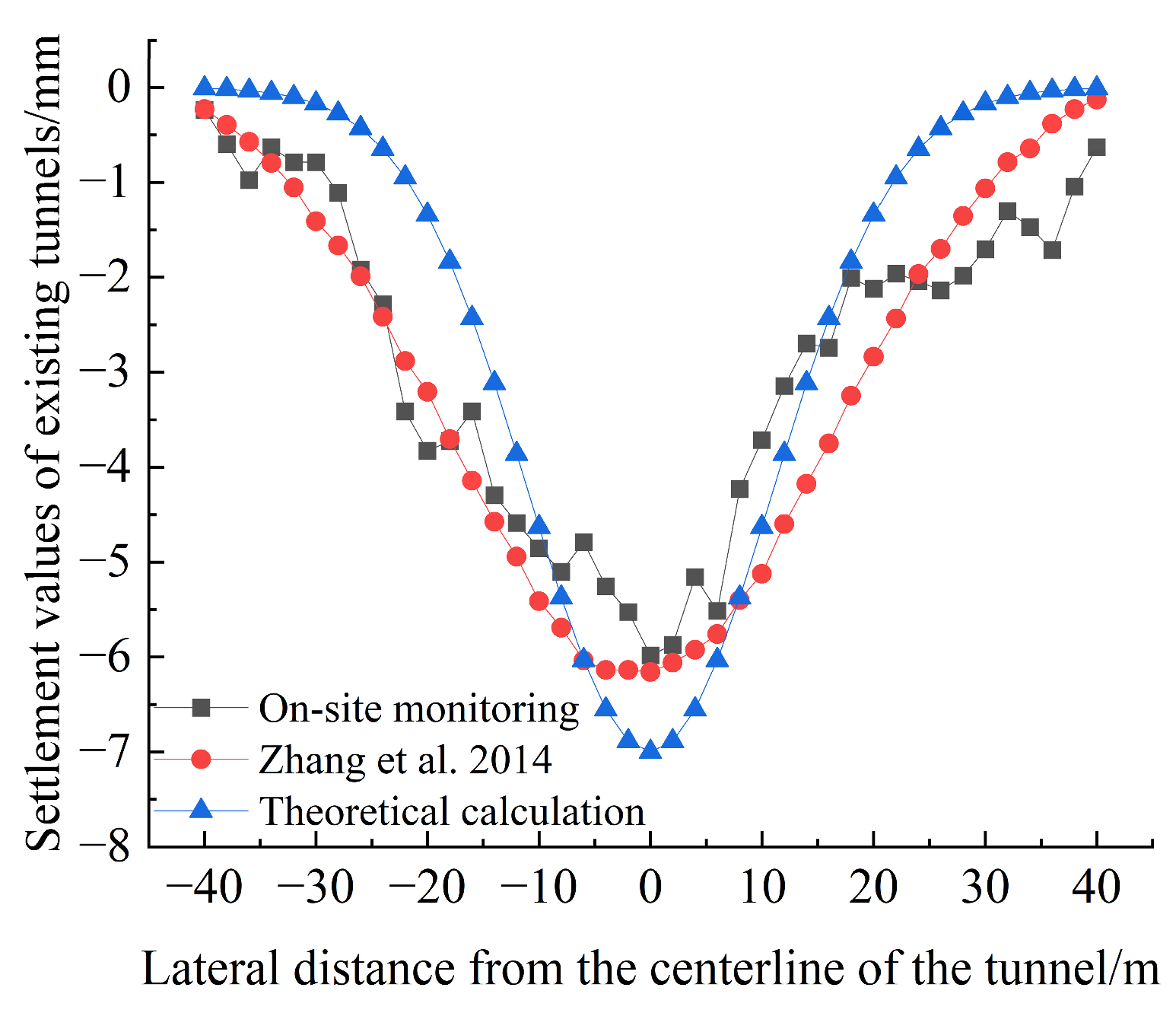
4.2. Engineering Case 2

A new tunnel under the existing tunnel project in Shanghai [29]. The axial depth of the new tunnel is 20.1 m, and the radius of the tunnel is 3.1 m. The axial depth of the existing tunnel is 9.1 m, and the diameter of the tunnel is 6.2 m. The length of the shield machine is 9 m, and one ring is taken to be 1.2 m; the equivalent bending stiffness of the tunnel is 1.087 × 10⁸ kN·m. The modulus of elasticity of the foundation soil is 16.49 MPa, Poisson’s ratio is 0.35, and soil loss rate is 0.75%. The blade thrust during construction was taken as 200 kPa, the shield shell friction was 150 kPa, and the grouting pressure was 120 kPa.
Figure 11 shows the vertical displacement curves of the tunnel calculated by the two methods in this case. The tunnel settlement calculated by this paper’s method and the literature [29] are more consistent in both value and trend, which shows that the existing tunnel deformation prediction model proposed in this paper also has certain applicability and accuracy for different engineering situations.

5. Analysis of Influencing Factors

When the soil and construction conditions surrounding the tunnel are uniform, factors such as the spatial relationship between the old and new tunnels, stratigraphic conditions, and other elements significantly influence the deformation of the existing tunnel. Consequently, leveraging the previously discussed theoretical approaches, the new sewage pipe project in Macao examines the depth and diameter of the new tunnel, as well as the influence of ground loss rate on tunnel settlement deformation. This analysis is based on the specific working conditions to aid in determining the gradient of parameter changes. Take the initial parameters of the new tunnel depth of 12 m, the new tunnel diameter of 4 m, and the rate of loss of the ground to remain unchanged.

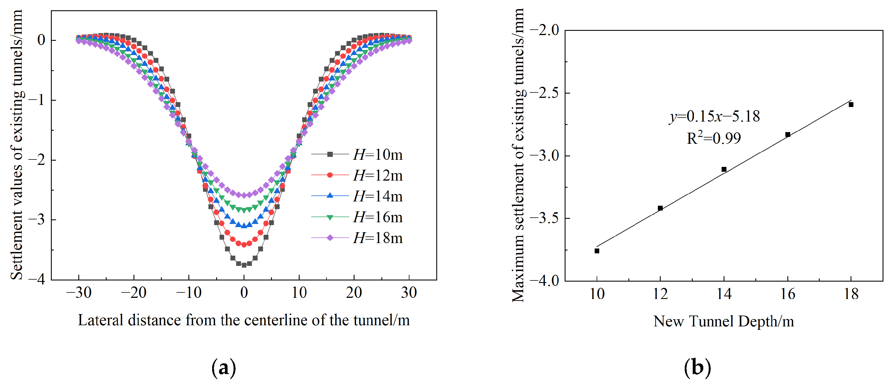
5.1. New Tunnel Depth

Take the new tunnel burial depths of 10 m, 12 m, 14 m, 16 m, and 18 m, respectively, for the calculation of the working conditions, which can be obtained under different new tunnel burial depths of the existing tunnel settlement and deformation distribution law, as shown in Figure 12a. As the depth increases, the width of the existing tunnel settlement groove increases and the settlement value gradually decreases. The change curve of the maximum settlement value of each sinkhole curve must be analyzed in relation to the burial depth of the new tunnel, as illustrated in Figure 12b. It is observed that as the burial depth of the new tunnel increases, the maximum settlement value of the existing tunnel decreases. Furthermore, when the burial depth exceeds 14 m, the degree of influence experiences a gradual decline, which occurs when the clear distance between two tunnels is greater than 6 m. This is referred to as the one-dimensional (1D) case. It has been demonstrated that, as the distance between two tunnels is increased, the ground deforestation caused by tunnel excavation is gradually transferred to the ground layer in which the existing tunnel is located. This process also results in a reduction of the induced settlement deformation of the existing tunnel.

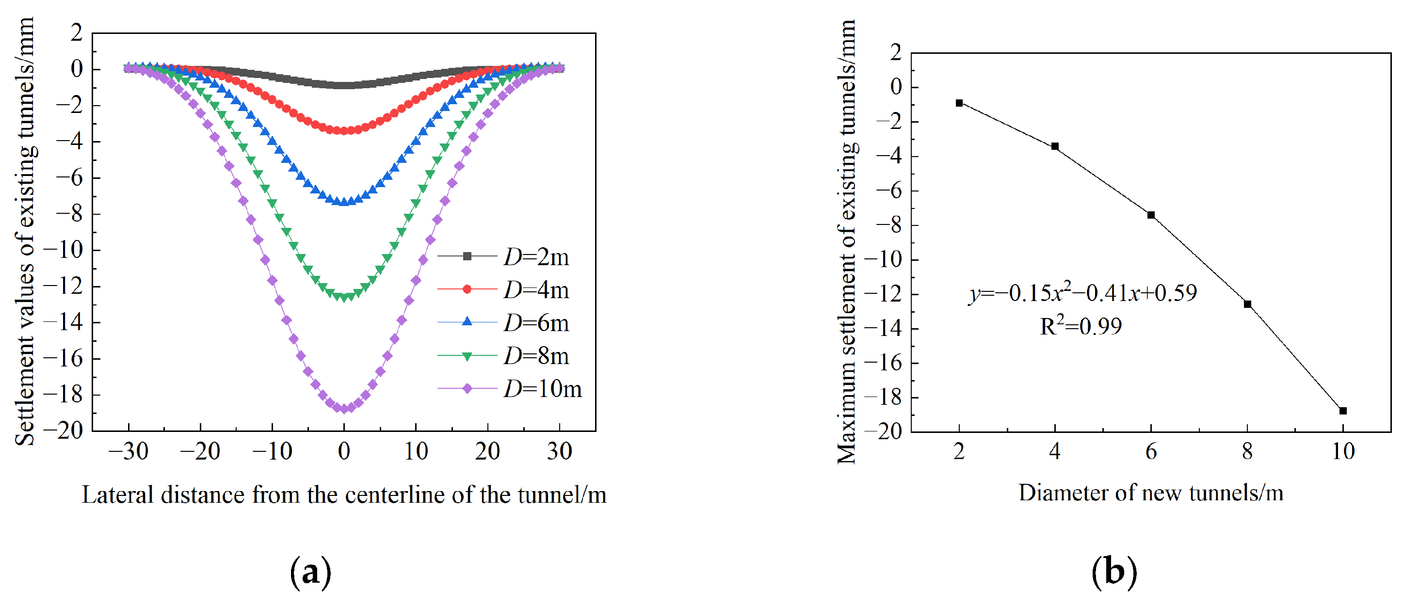
5.2. New Tunnel Diameter

The new tunnel excavation diameters of 2 m, 4 m, 6 m, 8 m, 10 m, and other conditions are chosen for calculation in conjunction with the features of urban corridors, tunnels, and other subterranean projects. The results of the settlement and deformation distribution of existing tunnels are displayed in Figure 13a. The settlement increases as the new tunnel’s excavation diameter increases. On the one hand, a larger new tunnel’s diameter results in a higher initial ground stress of the stratum in which the tunnel is located, and shield tunneling will destroy the original limit equilibrium state, potentially causing more additional stress. On the other hand, as the diameter increases, the volume of the stratum will decrease exponentially, which further causes additional stress, leading to an increase in the existing tunnel’s settlement and deformation.
The relationship between the diameter of the new tunnel excavation and the maximum settlement deformation of the old tunnel is shown in Figure 13b. The existing tunnel’s maximum settlement rises with the new tunnel’s diameter, and the two have a nearly positive exponential relationship. The previous tunnel’s settling is significantly impacted by the larger tunnel diameter.

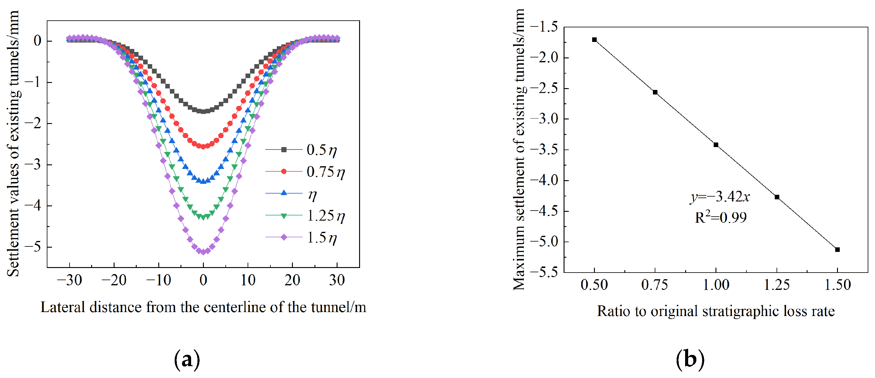
5.3. Stratigraphic Loss Rate

Taking the original strata loss rate η as a variable, the strata loss rate is set as 0.5 η, 0.75 η, 1.25 η, and 1.5 η, respectively. Subsequently, results of the settlement deformation can be obtained for different layer loss rates, as shown in Figure 14a. The settlement gradually increases as the strata loss rate increases. The term stratum loss rate denotes the proportion of volume reduction of the strata during the construction process. It can be deduced that a greater loss rate will result in a greater additional load acting on the existing tunnel. As demonstrated in Figure 14b, a positive correlation exists between the rate of strata loss and the maximum settlement value. With the increase of the strata loss rate, the maximum settlement value increases gradually. It is evident that when the loss rate is altered from 0.5 η to 1.5 η, the maximum settlement value of the existing tunnel is observed to increase from 1.71 mm to 5.13 mm. This shows that the rate of soil loss has a significant effect on the maximum settlement of the existing tunnel.

6. Engineering Optimization Recommendations

In the field of engineering, the depth, diameter, and ground loss rate of a tunnel are pivotal parameters in the design and construction of tunnel underpasses. In order to analyze the influence of these parameters on the settlement of existing tunnels, a sensitivity analysis can be performed. This analysis will determine the sensitivity factor of each parameter. Based on this, recommendations can be made for the optimization of the construction of new tunnels.

6.1. Analysis Method

The establishment of a system model is imperative for conducting a parameter sensitivity analysis [30], that is, the determination of the functional relationship between system characteristics and factor P = f x 1 , , x k x n . When analyzing the influence of parameters on the characteristic P, the rest of the parameters x 1 , x 2 x n can be made to take the base value and fixed value, and the parameters x k can be made to change within their possible range, then the system characteristic P can be defined as:
P = f x 1 , , x k x n = φ x k
It can thus be determined that the variation curve of maximum settlement of the extant tunnel is the P x k characteristic curve. Combined with the results of the analysis of the influencing factors, the sensitivity of the system characteristics P to the perturbation of the parameters x k can be given. According to the P x k curve, we can understand the sensitivity of the system characteristics to a single factor. When a small change in the parameter x k causes a large change in P, the parameter is highly sensitive, and vice versa for low sensitivity.
To better compare the sensitivity of the three factors, the depth of the new tunnel, its diameter, and the rate of ground loss, to the existing tunnel, a dimensionless sensitivity function is introduced:
S k x k = Δ P P / Δ x k x k ( k = 1 , 2 , , n )
where: S k is the sensitivity of the parameter x k ; Δ P / P is the relative rate of change of the system characteristic P; Δ x k / x k is the relative rate of change of the parameter x k ; the larger the parameter S k change, the larger the effect on the system. In the smaller case of Δ x k / x k , after derivation, S k x k can be approximated as follows:
S k x k = d φ x k d x k x k φ x k ( k = 1 , 2 , , n )
The sensitivity factor S k of the parameter x k can be obtained by substituting the parameter x k = x k into the above equation, as shown in Table 2. x k is the parameter base value, determined by the initial calculation parameters set.
It can be seen that the diameter has the greatest influence on the existing tunnel, with a sensitivity factor of 1.87, followed by the rate of stratum loss, with a sensitivity factor of 1, and finally the depth, with a sensitivity factor of 0.53.

6.2. Optimization Recommendations

The diameter of the newly constructed tunnel exerts the most significant influence on the existing tunnel. When the burial depth of the newly constructed tunnel is within 1D of the existing tunnel (D representing the diameter of the existing tunnel), it is evident that the extant tunnel has been more significantly impacted by the excavation of the newly constructed tunnel. Consequently, when designing the construction of the underpass, excavation should be avoided within 1D of the existing tunnel. For large diameter tunnels, it is recommended to adopt the construction method of step-by-step excavation and segmental support, and to closely monitor the existing tunnel during the construction process. The magnitude of the stratum loss rate exerts a substantial influence on the settlement of the existing tunnel. Consequently, during the construction period, measures such as grouting and reinforcing the soil surrounding the existing tunnel [31] should be considered, accompanied by stringent control of the travelling attitude. In addition, the use of shield machines has been shown to minimize the impact of stratum disturbance. Furthermore, the implementation of ring support reinforcement has been proposed as a means to ensure the safety of the existing tunnel during the construction of the new tunnel. The depth to which the new tunnel is buried also has a certain impact on the existing tunnel, and it is necessary to strictly grasp the clear distance between the new and old tunnels. It is recommended that, in the case of shallow tunnels, a smaller excavation step be used, and grouting reinforcement measures be taken in time, with a view to reducing any impact on the existing tunnel.

7. Conclusions

A deformation calculation method for existing tunnels considering construction factors and soil loss is proposed, which can provide some theoretical support for analyzing the impact of shield tunnels passing through existing tunnels. The main conclusions are as follows:
(1) The additional stress induced by the excavation of the existing tunnel is determined using the Mindlin stress solution and the three-dimensional Loganathan formula. Subsequently, the settlement of the existing tunnel caused by the underpassing new tunnel is calculated by integrating this stress analysis with the energy variational method. Field tests and numerical simulations have been conducted for the sewage pipe project in the Macao New Port area, and the results have been compared and verified against theoretical calculations. Compared with the existing method, which mainly considers soil loss, this paper considers the influence of construction factors on the deformation of existing tunnels, and the proposed calculation method fits well with the measured data and numerical simulation results, with an error of only 14.8%, compared to the existing method with an error of 31.3%.
(2) The settlement of the existing tunnel is primarily attributed to the loss of soil resulting from the utilization of the shield tunnel boring machine. The tunnel in question exhibits gradual settlement, with the maximum settlement observed at the centerline of the tunnel. As the excavation surface of the shield gradually approaches the existing tunnel, the rate of change of settlement increases. Upon reaching the existing tunnel directly below, the rate of change reaches its maximum. Once the tail section of the shield machine has passed through the existing tunnel, the settlement tends to stabilize. The final settlement was calculated to be 2.52 mm.
(3) A parameter sensitivity analysis was carried out for the depth of the new tunnel, its diameter, and the loss rate of the strata. The existing tunnel’s level of settlement is reduced in proportion as the new tunnel’s depth increases. Conversely, an increase in the new tunnel’s diameter or the rate of strata loss results in greater settlement of the existing tunnel. The diameter has the most significant effect on the settlement, with a sensitivity factor of 1.87, which is higher than the ground loss rate of 1 and the new tunnel depth of 0.53.

Author Contributions

Conceptualization, L.C. and Y.-L.L.; methodology, L.C., J.Z., J.-H.X., Y.-L.L. and G.-L.Y.; validation, L.C.; formal analysis, L.C.; investigation, L.C.; resources, Y.-L.L.; data curation, L.C. and Y.-L.L.; writing—original draft preparation, L.C.; writing—review and editing, Y.-L.L. and L.C.; visualization, L.C.; supervision, Y.-L.L. All authors have read and agreed to the published version of the manuscript.

Funding

This work was supported by the Science and Technology Research and Development Program Project of China Railway Group Limited (Grant No. 2023-Major-03).

Institutional Review Board Statement

Not applicable.

Informed Consent Statement

Not applicable.

Data Availability Statement

The data presented in this study may be available on reasonable request from the corresponding author.

Acknowledgments

The authors would like to acknowledge the China Railway Sixth Group Co., Ltd. and the China Railway Tunnel Group Co., Ltd. for providing detailed information about the design, construction as well as the monitoring data of project.

Conflicts of Interest

The authors declare no conflicts of interest.

References

  1. Jin, J.W.; Hao, S.; Cui, W.; Li, M.Y. Investigation of Underpass and Railway Track Settlements Induced by Shield Tunneling Through In Situ Test and 3D FEM Simulation. Int. J. Civ. Eng. 2023, 21, 1801–1811. [Google Scholar] [CrossRef]
  2. Sun, J.; Pei, X.K.; Yang, C.; Zhu, B.Z. Dynamic response analysis of the process of the utility shield tunnel under-passing the operating subway tunnel. Electron. J. Struct. Eng. 2023, 23, 44–52. [Google Scholar] [CrossRef]
  3. Lin, Y.L.; Lu, S.D.; Yang, G.L.; Zhang, P.R.; Shuai, J.G.; Fu, X. Field experimental study on construction mechanical characteristics of shallow buried biased pressure multi-cavity tunnel portal section. J. Cent. South Univ. 2023, 54, 4720–4731. [Google Scholar]
  4. Jiang, J.; Long, Y.H.; Ou, X.D.; Xing, X.W.; Zhang, T. Settlement analysis of existing tunnels caused by underpass construction of shield tunnel for new curved subway. Eng. Sci. Technol. 2023, 55, 313–324. [Google Scholar] [CrossRef]
  5. Chen, T.; Zhou, K.; Wei, J.; Liu, X.C.; Lin, Y.L.; Zhang, J.; Shen, Q. Analysis on the excavation influence of triangular-distribution tunnels for the wind pavilion group of a metro station. J. Cent. South Univ. 2020, 27, 3852–3874. [Google Scholar] [CrossRef]
  6. Zeng, L.H.; Zhang, D.B.; Lian, C.J.; Zhang, J.H.; Yin, H.D. Study on the influence of an under-crossing parallel double-line shield tunnel on the existing tunnel structure. Mathematics 2023, 11, 3125. [Google Scholar] [CrossRef]
  7. Gan, X.L.; Yu, J.L.; Gong, X.N.; Zhu, M. Characteristics and countermeasures of tunnel heave due to large-diameter shield tunneling underneath. J. Perform. Constr. Facil. 2020, 34, 04019081. [Google Scholar] [CrossRef]
  8. Weng, X.L.; Yu, H.F.; Niu, H.S.; Hu, J.B.; Han, W.W.; Huang, X.M. Interactive effects of crossing tunnel construction on existing tunnel: Three-dimensional centrifugal test and numerical analyses. Transp. Geotech. 2022, 35, 100789. [Google Scholar] [CrossRef]
  9. Shi, Y.Z.; Lin, L.Q.; Xu, J.N.; Qin, J.J. Mechanical analysis of expansion soil tunnel construction under humidified condition with close penetration of existing subway station. J. Railw. Sci. Eng. 2021, 18, 200–210. [Google Scholar] [CrossRef]
  10. Lai, H.P.; Zheng, H.W.; He, Q.M.; Liu, H.Y. Research on optimization of construction parameters of shield tunnel construction with small angle slanting down through existing tunnel in sandy soil stratum. China J. Highw. 2018, 31, 130–140. [Google Scholar]
  11. Xu, Q.; Zhu, Y.Q.; Lei, S.X.; Liu, Y.; Zhao, W.; Fang, Z.C.; Wang, C.; Xu, S. Improved stochastic medium theory model for prediction of deformation of existing tunnels and strata caused by tunnel underpass construction. J. Geotech. Eng. 2023, 45, 301–309. [Google Scholar]
  12. Liang, R.Z.; Zong, M.F.; Kang, C.; Wu, W.B.; Fan, Y.X.; Xia, T.D.; Cheng, K. Longitudinal impact of tunnel underpass on existing shield tunnel considering tunnel shear effect. J. Zhejiang Univ. 2018, 52, 420–430+472. [Google Scholar]
  13. Liu, X.; Fang, Q.; Zhang, D.L. Mechanical responses of existing tunnel due to new tunnelling below without clearance. Tunn. Undergr. Space Technol. 2018, 80, 44–52. [Google Scholar] [CrossRef]
  14. Gan, X.L.; Yu, J.L.; Gong, X.N.; Zhu, M.; Cheng, K. Study on the impact of new double-lane tunnels on existing shield tunnels. J. Rock Mech. Eng. 2020, 39, 3586–3594. [Google Scholar] [CrossRef]
  15. Zhang, Z.G.; Chen, J.; Zhu, Z.G.; Wei, G.; Wu, Z.T.; Lu, Z. Analysis of longitudinal deformation of existing discontinuous tunnel induced by shield penetration based on Kerr foundation model. J. Geotech. Eng. 2023, 45, 2238–2247. [Google Scholar] [CrossRef]
  16. Liu, X.Q.; Liang, F.Y.; Zhang, H.; Chu, F. Energy variational analysis method for vertical displacement of underground pipeline caused by tunnel crossing. Rock Soil Mech. 2014, 35, 217–222+231. [Google Scholar]
  17. Wei, G.; Cui, C.H.; Xu, X.; Zhang, X.H. Calculation of pipeline settlement caused by double-circle shield construction based on energy method. J. Undergr. Space Eng. 2019, 15, 1106–1111. [Google Scholar]
  18. Liu, T.Y.; Luo, W.J.; Yan, J.W.; Jiang, X.H. Settlement study of twin-lane underpass existing tunnels based on energy method. Eng. Sci. Technol. 2024, 56, 203–211. [Google Scholar] [CrossRef]
  19. Avramidis, I.E.; Morfidis, K. Bending of beams on three-parameter elastic foundation. Int. J. Solids Struct. 2006, 43, 357–375. [Google Scholar] [CrossRef]
  20. Yu, J.; Zhang, C.R.; Huang, M.S. Foundation modulus of buried pipelines under passive condition. J. Rock Mech. Eng. 2012, 31, 123–132. [Google Scholar] [CrossRef]
  21. Xu, L. Study on Longitudinal Settlement of Shield Tunnel in Soft Soil; Tongji University: Shanghai, China, 2005. [Google Scholar]
  22. Li, Y.; Bian, X.W.; Peng, H.; Zhu, B.Q.; Zhou, Y.L. Additional Stress of Soil and Surface Settlement during Tunnel Shield Construction. Buildings 2023, 13, 1437. [Google Scholar] [CrossRef]
  23. Mindlin, R.D. Force at a point in the interior of a semi-infinite solid. Physics 1936, 7, 195–202. [Google Scholar] [CrossRef]
  24. Wang, H.X. Soil-pressure balance shield cutter plate crowding effect and cutter plate opening rate on shield frontal contact pressure. J. Civ. Eng. 2009, 42, 113–118. [Google Scholar]
  25. Zhu, H.H.; Xu, Q.W.; Liao, S.M.; Yu, N.; Fu, D.M.; Wu, X.S. Experimental study on jacking thrust modeling for soil-pressure balance shield construction. Geotech. Mech. 2007, 28, 1587–1594. [Google Scholar] [CrossRef]
  26. Liu, W.Z.; Dai, X.Y.; Sun, K.; Ai, G.P.; Lei, T. Calculation method of longitudinal deformation of metro shield tunnel overpassing existing line at short distance. Rock Soil Mech. 2022, 43, 831–842. [Google Scholar]
  27. Zhang, J.J. Analysis of Soil Deformation Caused by Shield Tunneling; Zhejiang University: Hangzhou, China, 2006. [Google Scholar]
  28. Zhang, Z.G.; Huang, M.S.; Xu, C.; Jiang, Y.J.; Wang, W.D. Simplified solution for tunnel-soil-pile interaction in Pasternak’s foundation model. Tunn. Undergr. Space Technol. 2018, 78, 146–158. [Google Scholar] [CrossRef]
  29. Zhang, D.M.; Zong, X.; Huang, H.W. Study on longitudinal deformation of built tunnel above caused by shield tunnel boring. Geotechnics 2014, 35, 2659–2666. [Google Scholar] [CrossRef]
  30. Liu, L. Analysis of surface settlement and its sensitivity caused by shield construction of a two-lane tunnel under soft ground. Build. Struct. 2021, 51, 1707–1712. [Google Scholar]
  31. Zhu, T.; Huang, F.; Li, S.; Ouyang, T.Y.; Ying, J.; Zhao, H.R. Optimization of pre-grouting construction and evaluation of grouting effect in a deeply buried silt-filled shield tunnel. Tunn. Undergr. Space Technol. 2024, 152, 105902. [Google Scholar] [CrossRef]
Figure 1. Impact analysis model for new tunnels passing under existing tunnels.
Applsci 15 02430 g001
Figure 2. Schematic diagram of Mindlin solution for concentration force.
Applsci 15 02430 g002
Figure 3. Schematic diagram for the cutter plate’s increased thrust calculation.
Applsci 15 02430 g003
Figure 4. Shield friction calculation schematic diagram.
Applsci 15 02430 g004
Figure 5. Calculation flow chart.
Applsci 15 02430 g005
Figure 6. Diagrammatic representation of the project model.
Applsci 15 02430 g006
Figure 7. Arrangement of measurement points through the section.
Applsci 15 02430 g007
Figure 8. Three-dimensional numerical calculation model.
Applsci 15 02430 g008
Figure 9. Comparing existing tunnel lateral deflection curves [18].
Applsci 15 02430 g009
Figure 10. Comparison of existing tunnels’ longitudinal deformation curves.
Applsci 15 02430 g010
Figure 11. Comparison of settlement values of existing tunnels [29].
Applsci 15 02430 g011
Figure 12. The existing tunnel’s settlement for various additional tunnel depths: Settlement overall (a); settlement maximum (b).
Applsci 15 02430 g012
Figure 13. Settlement of the existing tunnel for different new tunnel diameters: (a) Overall settlement; (b) maximum settlement.
Applsci 15 02430 g013
Figure 14. Existing tunnel settlement under varying strata loss rates: Settlement overall (a); settlement maximum (b).
Applsci 15 02430 g014
Table 1. Physical and mechanical parameters of material.
Material TypeOntological
Relationship
Thicknesses/mModulus of
Compression/MPa
Capacity/(kN/m2)Cohesive Force/kPaAngle of Internal Friction/°Poisson’s Ratio
landfillMohr-Coulomb1.3891910280.25
oozeMohr-Coulomb2.02216.57.5250.32
silty clayMohr-Coulomb21.67.519.114260.35
gritMohr-Coulomb520202631.50.28
shieldelastic0.092.1 × 10578--0.3
Lining Pipe Sheetselastic0.22.88 × 10425--0.2
Grouting (before hardening)elastic0.1122--0.28
Grouting (after hardening)elastic0.110022--0.25
Table 2. Sensitivity results for each parameter.
Factor S ( x k ) x k S k
New Tunnel Depth 0.15 x 0.15 x + 5.18 120.53
Diameter of new tunnels 0.30 x 2 + 0.41 x 0.15 x 2 + 0.41 x 0.59 41.87
Stratigraphic loss rate111
Disclaimer/Publisher’s Note: The statements, opinions and data contained in all publications are solely those of the individual author(s) and contributor(s) and not of MDPI and/or the editor(s). MDPI and/or the editor(s) disclaim responsibility for any injury to people or property resulting from any ideas, methods, instructions or products referred to in the content.

