Abstract
This study presents a flywheel energy storage system utilizing a new multi-axial flux permanent magnet (MAFPM) motor–generator for coil launchers. The traditional winding structure of the flywheel is effective for energy recovery over several minutes. However, because the projectile is launched from coil launchers in less than one second, the traditional winding structure experiences insulation deterioration and winding damage due to the high current. This study proposes a winding structure made of an 8 × 0.5 mm conductor with eight turns to meet the energy requirements of coil launchers. Furthermore, the motor winding was divided into two sections, which were compared using both series and parallel connection methods as described in the literature. The proposed system produces energy that is 29.96%, 85.63%, and 81.11% lower than the A winding (where A and B are identical), the A + B winding (series connected), and A//B winding (parallel connected) at the same speed. However, as the speed increases by 258.26%, the energy output rises by 215.88%. The flywheel motor–generator’s series-parallel winding structure reaches its current carrying capacity at 1188 rpm. By utilizing a separate winding instead of the traditional motor–generator winding, a current of 38.4 A is achieved, ensuring that the winding’s current carrying capacity remains within the design parameters. Experimental data have proven that the proposed multi-wire winding structure is an innovative solution for coil launchers, surpassing various combinations of motor–generator windings found in the literature. Furthermore, the placement of the proposed winding in a single slot in the design ensures a compact structure.
1. Introduction
In recent years, studies on magnetic launcher systems have been increasing. These systems are considered for areas such as projectiles, aircraft, and space shuttle launchers [1,2,3,4,5,6]. Magnetic launcher systems are basically divided into two systems such as coil and rail launcher systems. The biggest challenge in a projectile-based coil magnetic launcher (CML) system is transferring energy to coils in under two seconds [5,6,7]. Super-capacitors are often used for this purpose [5,6,8,9,10]. However, in some studies, the use of a flywheel is suggested. In flywheel energy storage systems (FESS), different motor structures such as radial and axial can be used. The system suggested in this study consists of an AFPM machine.
In general, AFPMs are compact machines with high torque and high power density [11,12]. Thus, this study suggests that the AFPM machine structure is ideal for the flywheel energy storage system. However, cogging torque is their major disadvantage [13,14,15]. The cogging torque is the torque fluctuations between permanent magnet poles and the slot edges in no-load conditions. There are many methods in the literature on the rotor and stator side to eliminate the cogging torque. Among them, the methods applied to the rotor side are more economical and more accessible. The most common techniques that have been used on the rotor side can be listed as skew methods (classic, parallel, trapezoidal, and rounded skew), rotor shifting [16], slot use with different openings, magnet grouping [17], magnet placement angle changing [18], and different shaped magnet usage.
Flywheel energy storage systems are divided into low and high-speed systems. While low-speed energy storage systems are up to 6000 rpm, high-speed energy storage systems reach 60,000 rpm. Flywheel energy storage systems consist of parts such as a flywheel that stores the energy, a motor that accelerates the flywheel, a generator where the energy is recovered, a mechanical and magnetic bearing, and a vacuum body [19]. As the speed of the flywheel energy storage system increases, the amount of energy stored increases. However, the use of high-speed or magnetic bearings has disadvantages, such as increasing the hardness of the flywheel. So, this study suggests a low-speed flywheel energy storage system for the coil launcher.
FESS and supercapacitors are more advantageous than chemical batteries due to their high discharge current and high cycle life [20]. On the other hand, FESS comes to the fore with a higher energy density than supercapacitors [19]. FESS is recommended for a wide range of uses. Some of those are power fluctuations in wind power plants, energy storage in space shuttles, and aircraft launcher systems as well as the recovery of regenerative braking energy in electric vehicles, rail, and coil launchers [21].
When examining the literature, supercapacitors provide the high energy required to ensure the movement of the projectile in the coil launcher within less than 2 s [5,6]. However, the energy discharge time for a flywheel is 2 min, compared to just 1 min for supercapacitors [22]. Therefore, when the CML is powered by a flywheel, the discharge time, traditionally 120 s, must be reduced to under 2 s. In this study, conducted to address the deficiency of the flywheel, a power output of 1499.89 watts was achieved in 0.5 s using the proposed new winding design. Additionally, a more compact structure was realized by placing the newly designed winding in the same slots as the motor–generator winding used in the traditional design.
Axial flux machine structure is more compact than radial flux machines. In a radial-flux machine, the power increase varies with the machine length, while in an axial-flux machine, it is proportional to the machine diameter. Therefore, a new motor–generator set with AFPM is suggested for FESS. The suggested system has a separate generator winding design to obtain high energy in under two seconds and also has a separate AFPM motor design to keep the flywheel at 1188 rpm.
2. Materials and Methods
In this study, a new FESS design for CML is suggested. One of the two AFPM machines in the design operates in the low-speed stage (12 poles) and the other in the high-speed stage (2 poles). Moreover, the prominent feature is the separate generator winding in the 12-pole AFPM machine structure to obtain high energy in a short time and that there is a separate smaller powered 2-pole AFPM motor design to keep the flywheel at reference speed. With the use of windings in FESS’s conventional motor–generator set, high energy cannot be obtained in under two seconds. Thus, a separate generator winding is placed in the 12-pole AFPM machine structure. Also, at lower speeds, the multi-pole machine structure is ideal. At a high-speed stage, a few poles and a small-power AFPM motor structure could keep the flywheel at the reference speed.
FESS stores energy kinetically in a rotating flywheel. Since there is no chemical reaction, there is no change in the material due to charging and discharge. Thus, the cycle life of the material becomes longer. Therefore, FESS is useful in short-term high life cycle areas. FESS has traditionally been used for short-term energy fluctuations in power transmission lines, energy fluctuations in renewable energy production systems, and energy recovery in electric vehicles. In this study, the FESS design for CML was carried out with a compact AFPM machine that provides high torque and power density instead of a radial flux machine.
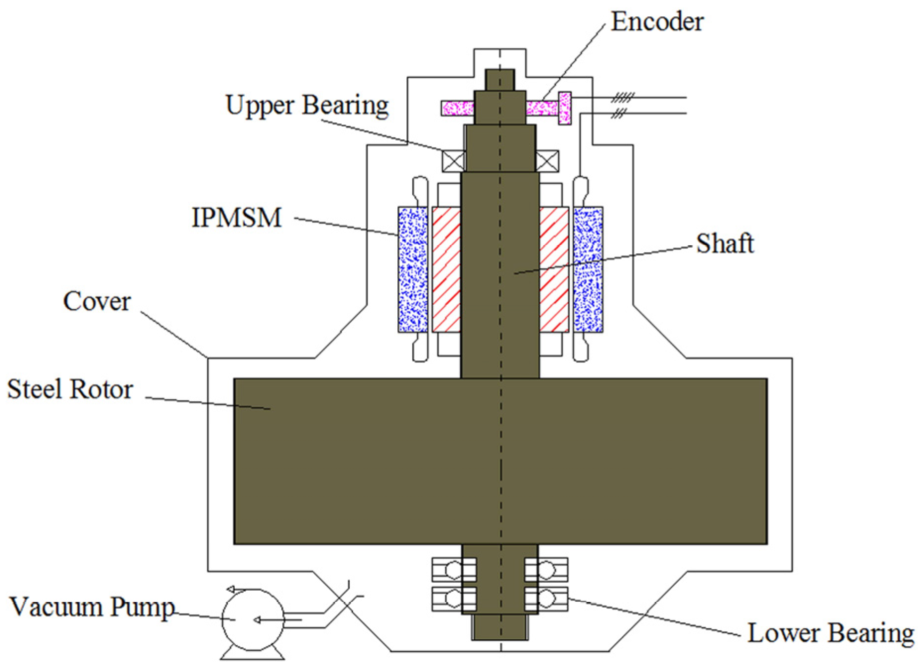
To avoid friction losses, FESS is operated in a vacuum environment. FESS, with a radial flux motor–generator set placed on the same shaft, is given in Figure 1. In Figure 1, the motor winding in FESS is also the generator winding. The discharge current is similar to the charging current since single winding is used. The existing motor must operate at a lower load to keep FESS in standby mode. Hence, the motor operates at a lower efficiency point.
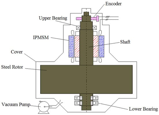
Figure 1.
The general structure of FESS [23].
FESS has over 20 years of lifetime [24]. Since the centrifugal forces are large in high-speed FESS, materials with high degree of hardness should be used [24]. Maximum energy amounts per unit volume and weight in FESS are given in Equations (1) and (2) [24].
In Equations (1) and (2); σ, ρ, and K, are the tensile strength, specific weight, and shape factor, respectively. The shape factor represents the maximum energy that can be stored depending on the shape of the flywheel. Shape factor is equal for the thick ring, thin ring, solid disc, and laval disc of 0.305, 0.5, 0.606, and 1, respectively [24]. In this study, the material used for energy storage is in the form of a solid disc (K = 0.606). Table 1 provides the unit weight for various materials, along with their respective constant and energy amounts per unit volume.

Table 1.
Values for different materials [24].
When Table 1 is examined, it is seen that the energy stored per kg and volume is proportional to the tensile strength, and the steel, which is the heaviest material, stores the lowest energy per kg. Since this study aims not to store material-related energy per unit volume or unit weight, aluminum material is preferred for ease of production.
FESS is an important component, especially in space applications. The comparison in terms of discharge depth, energy density, and life cycle in NASA’s study on FESS and NiH2 batteries are given in Table 2 [25].
Table 2.
Comparison of NiH2 batteries with FESS [25].
As seen in Table 2, NASA’s FESS shows superiority in life cycle, depth of discharge, and cycle efficiency. FESS is a candidate for use and development in many areas. So, a new design using two AFPM machine structures for CML is suggested. In the suggested motor–generator design, the amount of energy obtained by considering the charge and discharge conditions for 1000 rpm is given in Equation (3) [24]. In Equation (3), Em, j, and w are the maximum energy, moment of inertia, and angular velocity, respectively.
As the speed decreases from the reference value to zero, both the voltage and frequency approach zero. While recovering the energy, it is impossible to recover the maximum energy given in Equation (3). Hence, the energy between the two reference speed values must be recovered. The net amount of energy depending on the difference between the two reference angular velocity values is given in Equation (4) [24]. In Equation (4); Enet, wmax, and wmin are the net amount of energy, maximum angular velocity, and minimum angular velocity, respectively.
In this study, a new FESS design for CML is suggested. The 3D view of the suggested design is given in Figure 2. This design consists of 2-pole and 12-pole AFPM motors, a 12-pole generator winding, and an aluminum flywheel where the kinetic energy is stored.
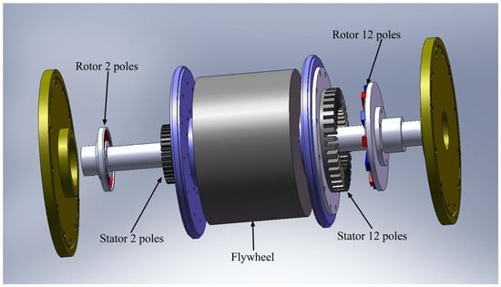
Figure 2.
Three-dimensional model of the designed FESS.
There is an AFPM machine structure on both sides of the flywheel in the proposed design. The 2-pole AFPM motor is designed to drive the flywheel to the high-speed reference point and hold its position. In the 12-pole AFPM motor–generator design, motor and generator windings are designed with different conductor sections and turn numbers to provide high energy capacity in the short time required by the CML. A compact design was obtained, as seen in Figure 2, by using the AFPM machine structure.
Figure 3 shows the experimental setup of the FESS design. 2p = 2 pole motor design has a toroidal winding structure. The 2p = 12 pole motor–generator structure consists of 3 trapezoidal windings. In the experimental setup, current and voltage values were measured using probes connected to the oscilloscope. The data were obtained by calculating the averages of the values recorded between 0 and 0.5 s. Values were also obtained at the desired reference speed point from 2p = 12 pole axial flux machine, using the driver shown in Figure 3. Also, this machine’s two windings are designed as the motor, and the third at the top is designed as the generator winding. The 2p = 12 pole motor windings are connected in series and parallel for energy storage performances. In addition, the energy storage amounts of the generator and motor windings of the 2p = 12 pole AFPM machine were compared.

Figure 3.
The designed FESS prototype.
Coil Magnetic Launcher
The coiled magnetic launcher is essentially an induction motor extended along a linear axis. The barrel features a structure with multi-phase excitation windings. The excitation voltage generated along the barrel travels toward the muzzle. The linear movement of the magnetic field generated by the windings interacts with the magnetic field produced by the voltages induced on the bullet in the barrel, causing the bullet to move toward the mouth of the barrel. Consequently, the factors influencing the speed of the bullet and the speed of the asynchronous motor are essentially the same. The difference is that the bullet is in only one section of the barrel. Therefore, the designed magnetic launchers are constructed in sections. In the coil launcher shown in Figure 4, the coils are triggered sequentially across three sections. As the projectile speed increases, the voltage frequency and amplitude applied to the windings decrease. This occurs naturally due to the reduced speed of the flywheel. Consequently, a driver circuit for frequency and voltage control is unnecessary. The bullet’s speed varies depending on the barrel length, as well as the frequency and number of phases [26].

Figure 4.
Multi-section coil launcher model [26].
3. Results
In this study, the difference from the literature is the AFPM motor design for two-speed stages and a generator winding in the 2p = 12 pole AFPM machine structure specially designed for CML. Magnetic analyses of two AFPM machines have been performed with the ANSYS Maxwell program (Version 14). For the suggested AFPM machines, the leg height (Lh), leg width (Lw), magnet angle (Md), and magnet height (Mh) parameters were gradually increased, and optimum points were obtained with the ANSYS Maxwell program. After the magnetic analysis, experimental data were obtained. In addition, in the 2p = 12-pole AFPM motor–generator set, the third winding obtained by using the conventional motor winding in the regenerative mode has been experimentally compared.
3.1. Magnetic Analyses
Magnetic analyses of the designs have been performed with the ANSYS Maxwell program. Firstly, magnetic analysis of the 2p = 2 pole high-speed stage was obtained. The 3D Maxwell model of the 2p = 2 pole AFPM motor is given in Figure 5.
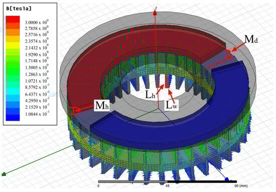
Figure 5.
Maxwell model of the 2p = 2 pole AFPM motor.
The design parameters of the 2p = 2 pole AFPM motor are shown in Figure 5. Magnetic analyses were performed with the ANSYS Maxwell program by iteration, the conventional optimization method. As a result of the magnetic analysis, the Lh, Lw, Md, and Mh values were 12 mm, 2.5 mm, 5°, and 7 mm, respectively [27]. The ratio of the total foot width to the circumference was obtained as σ = 0.377 for the Lw parameter. The ratio (σ) should not exceed the 0.4 value since the increase in the Lw parameter causes a decrease in the number of turns.
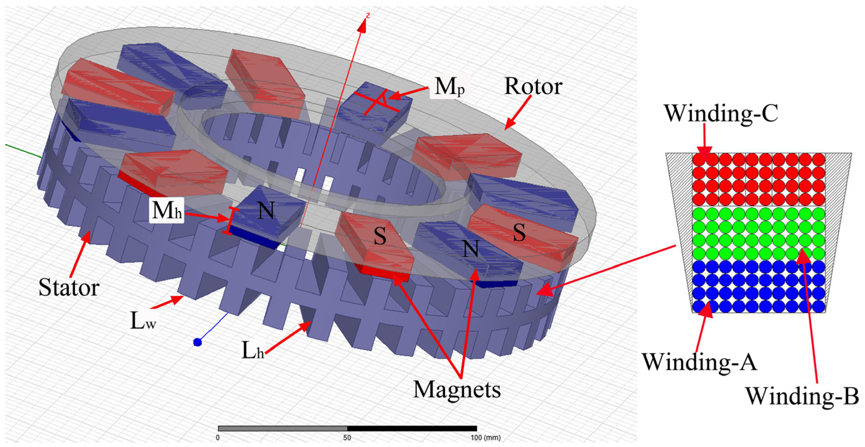
Maxwell model of the 2p = 12 pole motor–generator set designed for FESS is given in Figure 6. For the 2p = 12 pole AFPM motor–generator model; Lw, Lh, and magnet placement angle Mp values were found as 5.5 mm, 12 mm, and 30°, respectively. The design parameters Lw and Lh were used to determine the saturation points of the ferromagnetic core. As the ferromagnetic core becomes saturated, the magnetic flux density in the air gap decreases, negatively affecting machine performance. As a result of the analysis of the magnet placement angle, an improvement of 60% was obtained in the cogging torque for the determined 30°. In addition, the winding structure within the slots is segmented into three parts: A, B, and C, as illustrated in Figure 6. Windings A and B (toroidal winding type) are identical, each consisting of 40 turns of 0.5 mm cross-section conductor wire. Winding C (trapezoidalwinding type), on the other hand, is composed of 5 turns of the 8 × 0.5 mm conductor wire.
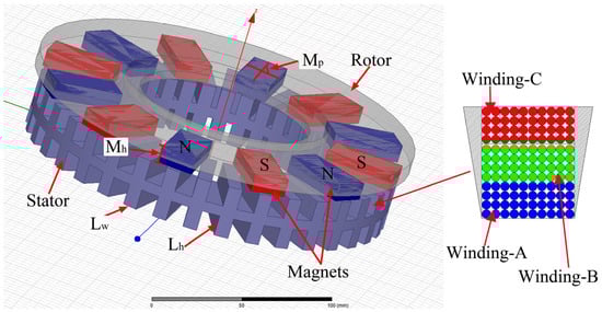
Figure 6.
Maxwell model of the 2p = 12 pole AFPM motor–generator.
3.2. Experimental Results
3.2.1. No-Load Operation
The number of slots per phase (ns) in the 2-pole and 12-pole AFPM machine winding designed for FESS is calculated from Equation (5) [28]. In Equation (5), x and m are the number of slots and number of phases, respectively.
In Equations (6)–(9), yx, c, α, f, and n are the number of steps, color number (slot number of phase under a pole), and the electrical angle (α), frequency, revolution per minute (rpm), respectively [27,28].
The winding values of the designed AFPM machines are calculated from Equations (5)–(8) and given in Table 3.
Table 3.
The winding (A–B–C) values of the designed AFPM machines.
An experimental setup of Flywheel was given in Figure 7. The experimental setup consists of two main components: a flywheel and an AFPM motor–generator. Other parts in the experimental setup are as follows: drive motor, oscilloscope, computer, loads, and current clamp. The loads shown in Figure 7 simulate the coil magnetic launcher. Consequently, the stage settings applied to the loads ensured that the flywheel was discharged with maximum current.
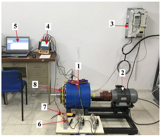
Figure 7.
Test setup for flywheel (1—Flyheell, 2—Drive motor, 3—Driver, 4—Oscilloscope, 5—Computer, 6—Loads, 7—Current clamp, 8—AFPM motor–generator).
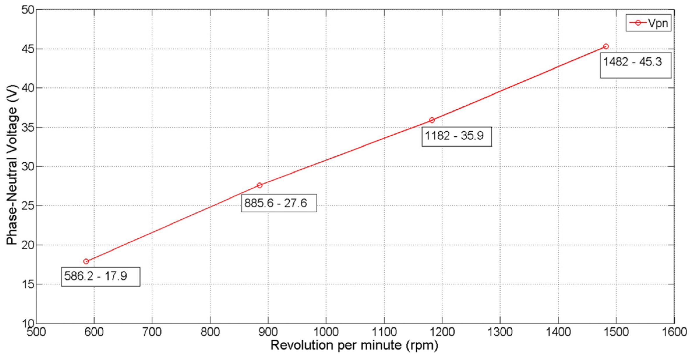
The electro-motor voltage values corresponding to the rpm of the 2p = 2 pole AFPM motor winding are given in Figure 8. When the values of Figure 8 are examined, 17.9 V at 586 rpm and 45.3 V at 1482 rpm are obtained. The values shown in Figure 8 represent the phase-neutral voltage (Vpn) obtained during the generator mode (idle operation) of the axial flux machine. An oscilloscope was utilized in the experimental study to measure these Vpn values. Additionally, the motor rpm values indicate the operating frequency. The frequency values corresponding to the Vpn-rpm pairs of 586.2–17.9, 885.6–27.6, 1182–35.9, and 1482–45.3 (Vpn-rpm), as shown in the graph, are 9.77, 14.76, 19.7, and 24.7 (Hz), respectively, according to Equation (9).
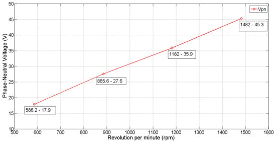
Figure 8.
2p = 2 Pole AFPM motor Vpn-rpm characteristic.
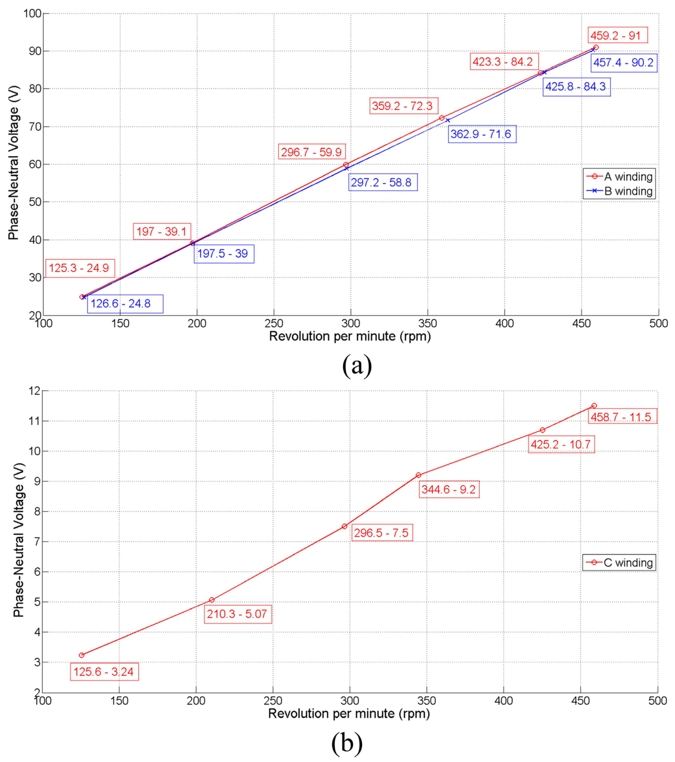
The electro-motor force (emf) values obtained from the 2p = 12 poles of AFPM motor–generator windings are given in Figure 9. As seen in Figure 9a, the A and B windings of the 2p = 12 pole AFPM motor–generator are identical. Since the C winding in Figure 9b, designed for CML, consists of 8-conductor winding; the emf is approximately 1/8 for the same revolution numbers. The Vpn values obtained from the oscilloscope are shown in Figure 9a,b. Figure 9a presents the frequency values for winding A as follows: 12.53 Hz at 125.3–24.9 Vpn-rpm, 19.7 Hz at 197–39.1 Vpn-rpm, 29.67 Hz at 296.7–59.9 Vpn-rpm, 35.92 Hz at 359.2–72.3 Vpn-rpm, 42.33 Hz at 423.3–84.2 Vpn-rpm, and 45.92 Hz at 459.2–91 Vpn-rpm, calculated using Equation (9).

Figure 9.
2p = 12 Pole AFPM motor Vpn-rpm characteristic (a) A–B windings and (b) C winding.
In the AFPM motor–generator set, the induced emf per revolution for the A and B windings is 0.197 volts and around 0.024 volts for the C windings. The C winding that is above the slot is less affected by leakage reactance than the A and B windings, which are at the bottom.
3.2.2. On-Load Operation Regenerative Model
In this study, the AFPM motor–generator set for FESS was developed for CML. In conventional motor–generator sets developed for FESS, motor windings are used as generator windings, either alone or connected in series and parallel. However, in the suggested AFPM motor–generator system, a separate generator winding is performed. Therefore, CML’s most suitable winding type in regenerative mode has been determined separately for A, B, and C windings. Here, A and B are motor windings, and C is generator windings.
The AFPM motor–generator set for FESS is gradually loaded in the regenerative mode for winding A. The regenerative mode should achieve the highest energy in the shortest time for CML. Experimental data were obtained by recording current and voltage values on the Fluke 190 series oscilloscope. When the flywheel reached a speed of 460 rpm, the loads were applied to the generator gradually.
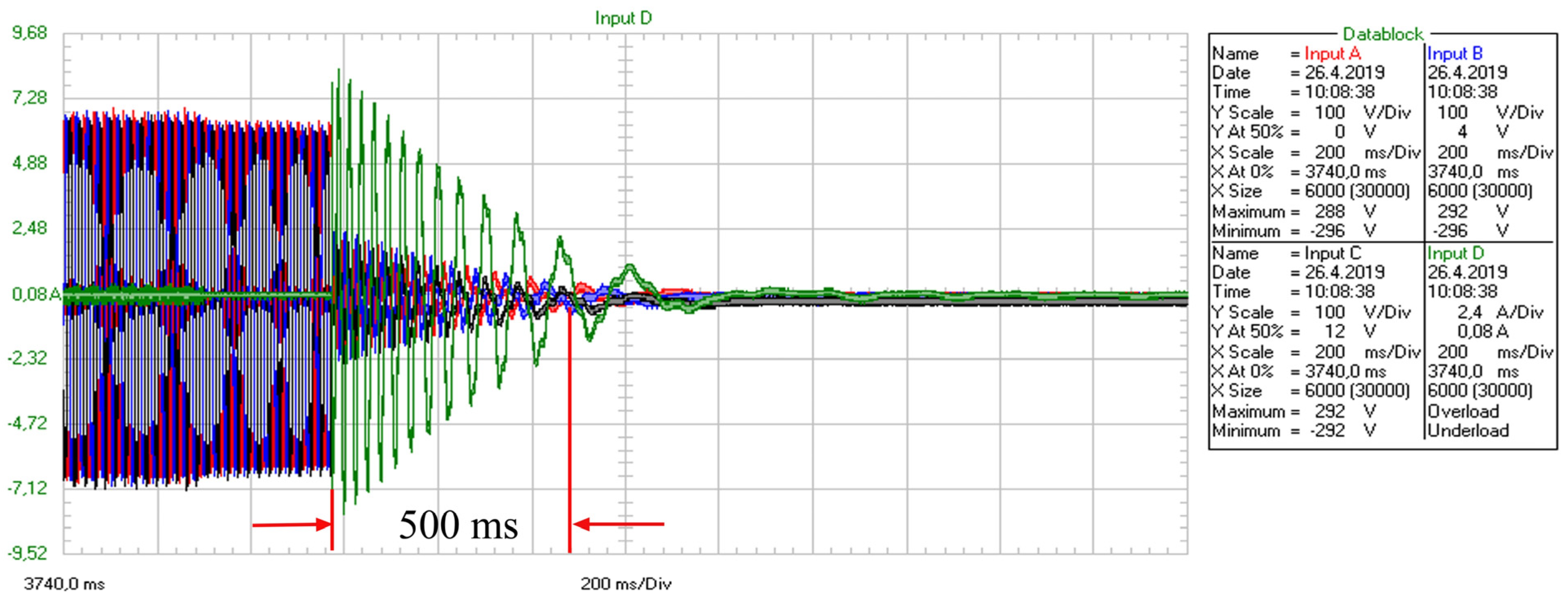
The values obtained in the regenerative mode for the sixth stage load condition of the A winding are given in Figure 10. Here, A, B, and C are voltage inputs, and D is the current input. As shown in Figure 10, when the load starts, the value of the voltage decreases while the current value increases. Each square on the measurement screen shows an interval of 0.2 s. The maximum current obtained from FESS is 7.28 A.
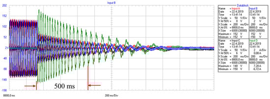
Figure 10.
The regenerative mode for the Vpn-Ipn 6th stage of A winding.
In Table 4, the average voltage phase-neutral (Vpn), average current phase-neutral (Ipn), and power (Watt/0.5 s) values for each load step are calculated for the A winding in regenerative mode. Values were obtained for the first 0.5 s of the load. It can be seen in Table 4 that as the step increases, the current increases, but the voltage decreases. For the A winding, the highest value of 332.42 watts of power was obtained in 0.5 s at the fourth stage with an average of 2.61 A.
Table 4.
The electrical values were obtained in 0.5 s for FESS.
The values obtained in the regenerative mode for the sixth stage load condition of the A + B series winding are given in Figure 11. Here, A, B, and C are voltage inputs, and D is the current input. As shown in Figure 11, when the load starts, the value of voltage decreases while the current value increases. The maximum current obtained from FESS is 8.08 A.
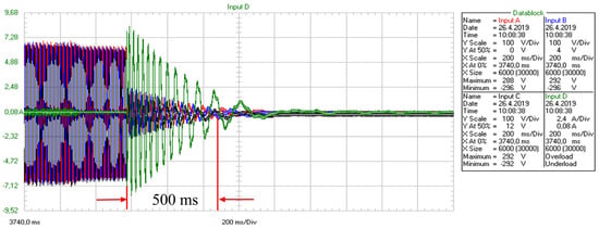
Figure 11.
The regenerative mode for the Vpn-Ipn 6th stage of A + B series winding.
In Table 5, the average voltage phase-neutral (Vpn), average current phase-neutral (Ipn), and power (Watt/0.5 s) values for each load step are calculated for the A + B series winding in regenerative mode. It can be seen in Table 5 that as the step increases, the current increases, but the voltage decreases. For the A + B series winding, the highest value of 474.03 Watts of power was obtained in 0.5 s at the second stage and an average of 2.32 A.
Table 5.
The electrical values obtained in 0.5 s for FESS.
The values obtained in the regenerative mode for the sixth stage load condition of the A//B parallel winding are given in Figure 12. Here, A, B, and C are voltage inputs, and D is the current input. As shown in Figure 12, when the load starts, the voltage value decreases while the current value increases. The maximum current obtained from FESS is 9.52 A.
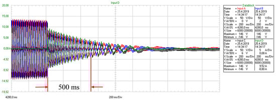
Figure 12.
The regenerative mode for the Vpn-Ipn 6th stage of A//B winding.
In Table 6, the average voltage phase-neutral (Vpn), average current phase-neutral (Ipn), and power (Watt/0.5 s) values for each load step are calculated for the A//B parallel winding in regenerative mode. It can be seen in Table 6 that as the step increases, the current increases, but the voltage decreases. For the A//B parallel winding, the highest value of 463.25 Watts of power was obtained in 0.5 s at the fifth stage and an average of 3.81 A.
Table 6.
The electrical values obtained in 0.5 s for FESS.
The values obtained in the regenerative mode for the eighth stage load condition of the C winding are given in Figure 13. As shown in Figure 13, when the load starts, the voltage value decreases while the current value increases. Therefore, the maximum current obtained from FESS is 40 A.
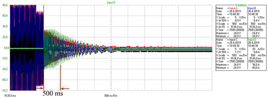
Figure 13.
The regenerative mode for the Vpn-Ipn 8th stage of C winding.
In Table 7, the average voltage phase-neutral (Vpn), average current phase-neutral (Ipn), and power (Watt/0.5 s) values for each load step are calculated for the C winding in regenerative mode. It can be seen in Table 7 that as the step increases, the current increases, but the voltage decreases. For the C winding, the highest value of 255.78 Watts of power was obtained in 0.5 s at the 8th stage with an average of 24.02 A. (Since the designed winding resistance is low, additions have been made to the load stages).
Table 7.
The electrical values obtained in 0.5 s for FESS.
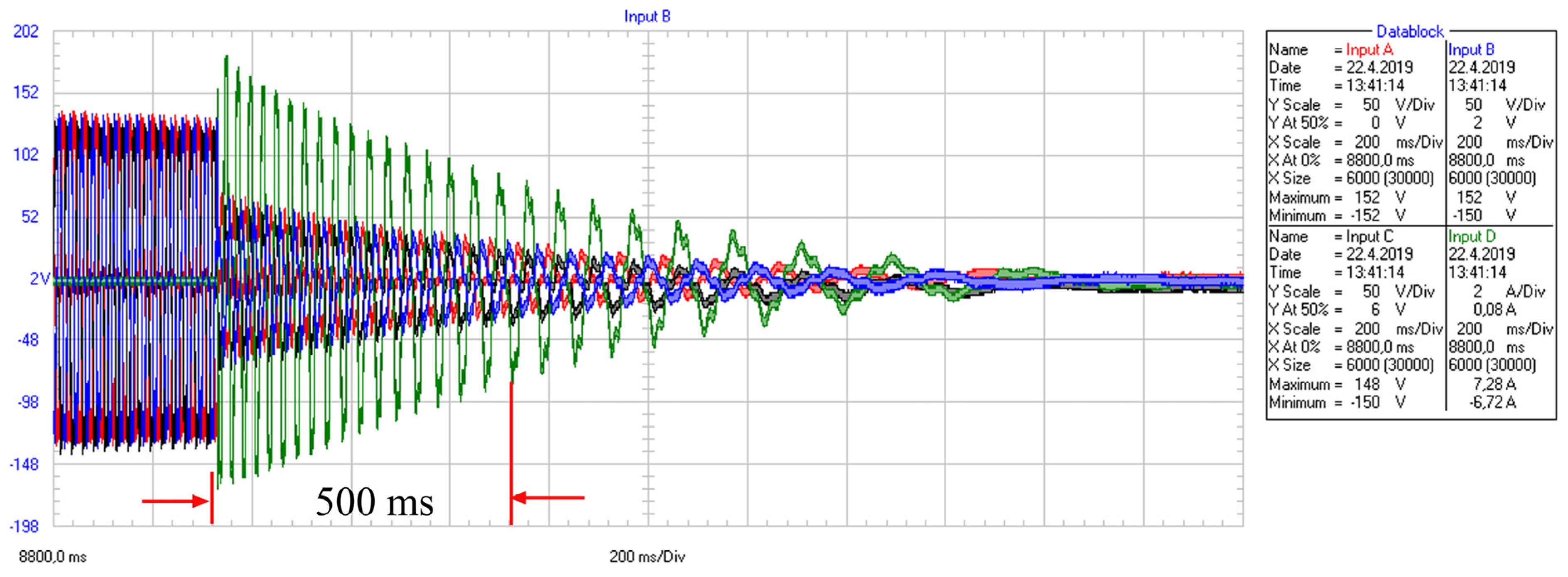
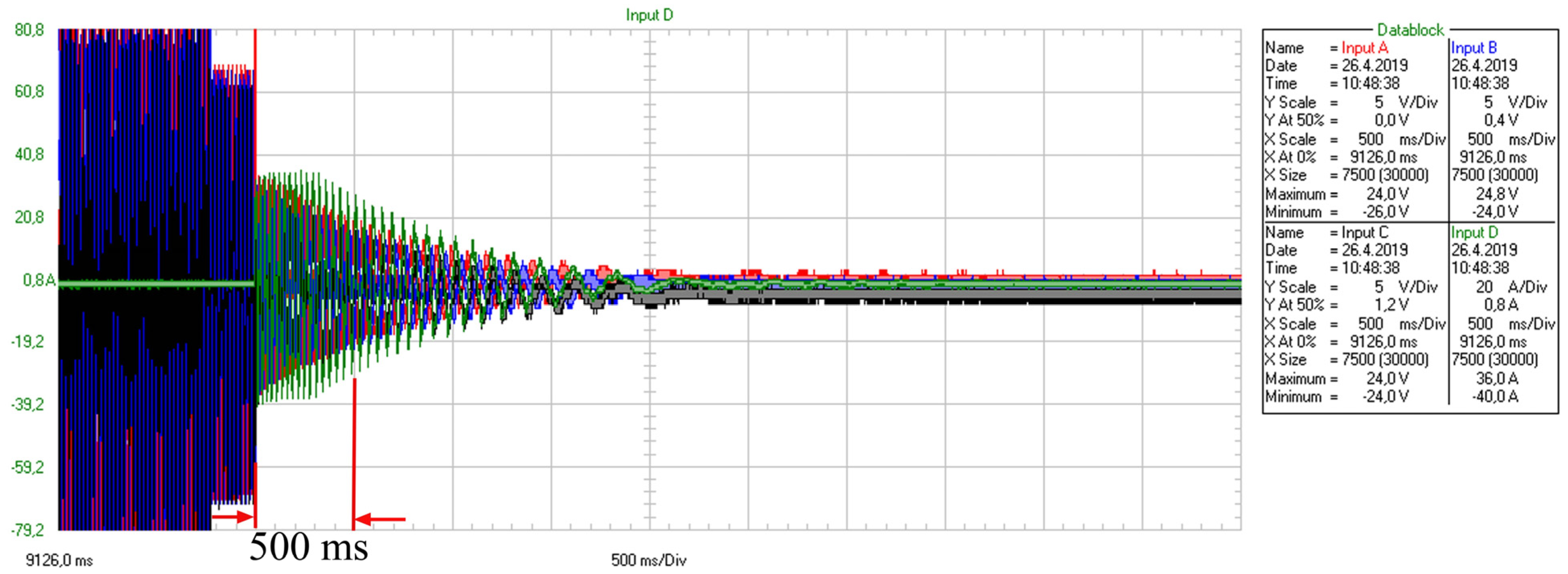
Because the designed winding C has a low emf value at 460 rpm reference speed, lower energy is obtained for the same rpm in the C winding designed for CML. Therefore, the experimental data obtained at a higher speed (1188 rpm-118.8 Hz) of the designed winding C are given in Figure 14. In the first 0.5 s of FESS, the average current was 19.74 A, and the average voltage was 25.32 V. Hence, the total power obtained in 0.5 s was 1499.89 Watts. As shown in Figure 14, the maximum current was 38.4 A, and the maximum voltage was 49.6 Volts.
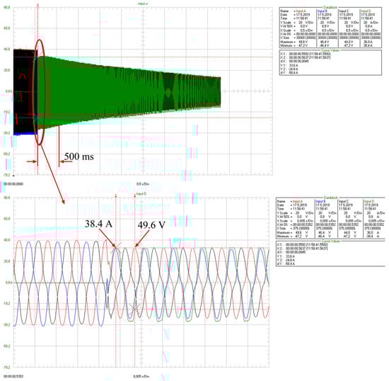
Figure 14.
The obtained values on 1188 rpm for C winding.
4. Discussion
In this study, a new flywheel design with a discharge winding that could give high current in a short time for BMF, and two AFPM machine structures are suggested. The suggested design consists of a low-speed stage AFPM motor, a high-speed stage AFPM motor, and an additional discharge winding on the low-speed stage motor winding. Thus, the flywheel reaches the reference speed in a short time with the high discharge current provided by the suggested system and has the advantage of low energy consumption at the reference speed.
For high discharge current output from the FESS, a separate winding was used instead of the existing winding of the 2p = 12 pole AFPM motor–generator. This discharge winding is called C. In addition, data were obtained by different connections with motor windings called A and B in 2p = 12 pole AFPM motor–generator and compared with the experimental data of the C winding.
In the study, first of all, magnetic analyses were carried out with 3D Maxwell for 2p = 2 and 2p = 12 pole AFPM machines.
Since the increase in the Lw parameter causes a decrease in the number of turns, the σ value is taken as 0.4 for the Lw parameter. At minimal values of σ, saturations occur in the core feet. So, the parameters were obtained with the ANSYS Maxwell program by classical optimization (iteration), considering the magnetic saturation points of the core.
- As a result of the magnetic analysis for 2p = 2 pole, Lw, Lh, Md, and Mh values were found to be 2.5 mm, 12 mm, 5°, and 7 mm, respectively;
- As a result of the magnetic analysis for 2p = 12 pole, Lw, Lh, and Mp values were found to be 5.5 mm, 12 mm, and 30°, respectively.
For the no-load state of the AFPM machine that was suggested for the flywheel energy storage system, the induced voltage values per rpm were obtained for the 2p = 2, 2p = 12, A, B, and C windings. When the AFPM machine operates as a motor, V/rpm values are an important parameter for drive design.
- For the 2p = 2 pole AFPM machine, the induced emf value per rpm was obtained as 0.0305;
- For the 2p = 12 pole AFPM machine, the induced emf value per rpm was obtained as 0.197 for A and B windings and 0.024 for C winding. Since C winding is 1/8 of A an B windings, the V/rpm value is also measured proportionally.
The study suggested a new Flywheel energy storage system for CML. In this system, three windings (A, B, and C), are designed for the 2p = 12 pole AFPM motor–generator structure. For CML systems, a high energy discharge current must be taken in a short time such as 0–2 s. In the literature, discharge processes are carried out by making a single or a 2-part (A, B winding) motor winding. Unlike the literature, the experimental results obtained from a separate generator winding (C winding) suggested in this study are given below. Experimental data were obtained by recording current and voltage values on the Fluke 190 series oscilloscope.
- For the winding A, 332.42 Watts of power were obtained in 0.5 s at 460 rpm, with the highest at 2.61 A;
- For the A + B series winding, 474.03 Watts of power energy was obtained in 0.5 s at 460 rpm and 2.32 A;
- For the A//B parallel winding, 463.25 Watts of power energy was obtained in 0.5 s at 460 rpm and 3.81 A;
- For the C winding (designed for BMF), 255.78 Watts of power energy was obtained in 0.5 s at 460 rpm and 24.02 A;
- For the C winding, 1499.89 Watts of power energy was obtained in 0.5 s at 1188 rpm and 38.4 A.
Although more current is obtained by connecting the winding in parallel on the AFPM motor–generator system, there is more voltage drop due to internal resistance and leakage reactance, which reduces the energy obtained. In the C winding, on the other hand, the current load increases with the design that increases the number of parallel arms of the winding. Thus, the amount of energy at higher speeds also increases.
In the future, studies could be carried out on the determination of the point where the maximum power occurs. In addition, it can be carried out to obtain more power from the flywheel in a short time by performing coreless and water-cooled winding designs at high rpm for BMF.
5. Conclusions
The flywheel designed in the study provides a significant advantage by providing energy in under 1 sec compared to traditional flywheels with their winding structure. Designed for CML, the traditional flywheel has a single-coil structure. This winding design is used both as a motor winding and as a generator winding. In designs where the motor and generator windings are used together, the discharge lasts for two minutes. Consequently, the discharge times of less than 2 s required for the coil launcher cannot be achieved. Therefore, it is not possible for the flywheel to be ready in under two seconds and provide high energy to the CML in less than 1 s. To eliminate this disadvantage, a motor and a motor–generator set were designed on the same shaft for the high energy capacity required by the CML in in under two seconds. While the multipole motor–generator set works to overcome the moment of inertia at low speed in motor mode, the 2-pole motor ensures that the flywheel reaches high speed in under two seconds. In addition, a third winding designed additionally on the multi-pole motor winding is used in order to meet the required energy need in under two seconds.
When the experimental results obtained are examined, regenerative power can be obtained by connecting the A–B windings in series and parallel. In the double-winding structure of the motor–generator set used in the traditional flywheel design, a maximum power output of 474.829 watts was achieved at 460 rpm. The emf generated at the 1188 rpm reference speed of the flywheel is five times higher than that of the C winding, owing to the number of turns in the A and B windings. Since the emf determines the discharge current flowing through the winding, it must be appropriate for the cross-section of the winding conductor. However, since the A–B windings are designed in accordance with the motor operating mode, the winding conductor cross-sections exceed their energy-carrying capacity in regenerative mode at high speeds. Therefore, it is not possible to obtain high current values in under two seconds with the regenerative mode, considering the conductor’s current carrying capacity. However, the insulation on the windings is damaged.
In the study, high discharge currents at high speeds (38.4 A at 1188 rpm) were obtained with the C winding designed with a winding cross-section of 8 × 0.5 mm. Thus, a new winding design and motor–generator set that reaches the reference speed in under two seconds and provides high regenerative energy has been verified with experimental data.
However, the new winding design offers a more compact structure. Based on the results of this study, mechanical improvements and new methods should be developed to enhance the reference speed in future research, thereby increasing the discharge of currents. Additionally, improving the efficiency of the motor–generator set used in the flywheel by examining solid and iron losses is an important area of study.
Funding
This research was funded by TÜBİTAK, project number 3501-115E964.
Data Availability Statement
Data are available at engin.huner@klu.edu.tr.
Conflicts of Interest
The author declares no conflicts of interest.
Abbreviations
The following abbreviations are used in this manuscript:
| MAFPM | Multi-axial flux permanent magnet | Lh | The leg height |
| CML | Coil magnetic launcher | Lw | The leg weight |
| FESS | Flywheel energy storage systems | Md | Magnet angle |
| AFPM | Axial flux permanent magnet | Mh | Magnet height |
| 3D | Three dimensional | σ | The ratio of the total foot width to the circumference |
| ev | Maximum energy amounts per unit volume | Mp | Magnet placement angle |
| K | Shape factor | ns | The number of slots per phase |
| σθ,u | Tensile strength | 2p | Pole number |
| em | Maximum energy amounts per unit weight | x | The number of slots |
| ρ | Specific weight | yx | The number of step |
| Em | The maximum energy | c | Color number |
| J | Moment of inertia | α | The electrical angle |
| w | Angular velocity | emf | The electro motor force |
| Enet | The net amount of energy | Vpn | The voltage of phase-neutral |
| wmax | Maximum angular velocity | Ipn | The current of phase-neutral |
| wmin | Minimum angular velocity | rpm | Revolution per minute |
References
- Mirzaei, M.; Abdollahi, S.E. Design Optimization of Reluctance-Synchronous Linear Machines for Electromagnetic Aircraft Launch System. IEEE Trans. Magn. 2009, 45, 389–395. [Google Scholar] [CrossRef]
- Abdo, M.M.M.; El-Hussieny, H.; Miyashita, T.; Ahmed, S.M. Design of A New Electromagnetic Launcher Based on the Magnetic Reluctance Control for the Propulsion of Aircraft-Mounted Microsatellites. Appl. Syst. Innov. 2023, 6, 81. [Google Scholar] [CrossRef]
- Dogangunes, S.; Balikci, A. Design and Implementation of a Linear Induction Launcher with a New Excitation System Utilizing Multi-Stage Inverters. Energies 2024, 17, 1302. [Google Scholar] [CrossRef]
- Jin, L.; Liu, L.; Song, J.; Yan, Y.; Zhang, X. Interval Uncertainty Optimization Method for Electromagnetic Orbital Launcher. Appl. Sci. 2023, 13, 8806. [Google Scholar] [CrossRef]
- Kim, S.; Jang, C.; Kim, J. Design and Experiment of Discharge Control Methods for Three-Stage Coil Gun Experiments. Appl. Sci. 2023, 13, 1779. [Google Scholar] [CrossRef]
- Guan, S.; Guan, X.; Wu, B.; Shi, J. Analysis of the Influence of System Parameters on Launch Performance of Electromagnetic Induction Coil Launcher. Energies 2022, 15, 7803. [Google Scholar] [CrossRef]
- Hou, Y.; Liu, Z.; Ouyang, J.; Yang, D. Parameter settings of the projectile of the coil electromagnetic launcher. In Proceedings of the 16th International Symposium on Electromagnetic Launch Technology, Beijing, China, 15–19 May 2012; pp. 1–4. [Google Scholar] [CrossRef]
- Chun, T.; Kim, H.; Nho, E. Charging and discharging strategies of grid-connected super-capacitor energy storage systems. In Proceedings of the 2018 IEEE International Conference on Industrial Technology (ICIT), Lyon, France, 20–22 February 2018; pp. 1743–1747. [Google Scholar] [CrossRef]
- Ma, W.; Lu, J.; Liu, Y. Research Progress of Electromagnetic Launch Technology. IEEE Trans. Plasma Sci. 2019, 47, 2197–2205. [Google Scholar] [CrossRef]
- Citak, H.; Ege, Y.; Coramik, M. Design and Optimization of Delphi-Based Electromagnetic Coilgun. IEEE Trans. Plasma Sci. 2019, 47, 2186–2196. [Google Scholar] [CrossRef]
- Pranjić, F.; Virtič, P. Determination of an Optimum Fictitious Air Gap and Rotor Disk Thickness for a Coreless AFPMM. Teh. Vjesn. 2018, 25, 1731–1738. [Google Scholar] [CrossRef]
- Subramaniam, S.; Bairavan Veerayan, M. Performance Evaluation of Novel Rare Earth Free Magnets Based Motors for Electric Vehicle Applications. Teh. Vjesn. 2023, 30, 1029–1038. [Google Scholar] [CrossRef]
- Bendib, M.H.; Hachemi, M.; Marignetti, F. Electromagnetic Design and Analysis of a Novel Axial-Transverse Flux Permanent Magnet Synchronous Machine. Electr. Power Compon. Syst. 2017, 45, 912–924. [Google Scholar] [CrossRef]
- Kim, K.C. A Novel Method for Minimization of Cogging Torque and Torque Ripple for Interior Permanent Magnet Synchronous Motor. IEEE Trans. Magn. 2014, 50, 793–796. [Google Scholar] [CrossRef]
- Zhang, G.; Hou, P. Optimization Design of Cogging Torque for Electric Power Steering Motors. Machines 2024, 12, 517. [Google Scholar] [CrossRef]
- Aydin, M.; Zhu, Z.Q.; Lipo, T.A.; Howe, D. Minimization of Cogging Torque in Axial-Flux Permanent-Magnet Machines: Design Concepts. IEEE Trans. Magn. 2007, 43, 3614–3622. [Google Scholar] [CrossRef]
- Hüner, E.; Mutlu, A. A new hybrid method for reducing cogging torque in the AFPM wind generator. Energy Sources Part A Recovery Util. Environ. Eff. 2022, 44, 853–870. [Google Scholar] [CrossRef]
- Hüner, E.; Zeka, G. Reduction of Cogging Torque and Improvement of Electrical Parameters in Axial Flux Permanent Magnet (AFPM) Synchronous Generator with Experimental Verification. Prog. Electromagn. Res. C 2020, 104, 99–113. [Google Scholar] [CrossRef]
- Kato, K.; Ishigma, S.; Nakajima, Y.; Arai, H.; Ueda, T.; Iwata, T.; Ito, Y.; Sugao, K. 10MW, 3.3MWh Energy Storage System consisting of 4000 Flywheels controlled by ICT network for Short Cycle Power Fluctuation Compensation. In Proceedings of the 2014 International Power Electronics Conference, Hiroshima, Japan, 18–21 May 2014; pp. 403–408. [Google Scholar] [CrossRef]
- Fu, X. A Novel Design for Flywheel Battery of Electric Vehicles. In Proceedings of the IEEE International Conference on Intelligent System Design and Engineering Application 2010, Changsha, China, 13–14 October 2010; pp. 107–111. [Google Scholar] [CrossRef]
- Junfeng, W. Design of a Miniature Axial Flux Flywheel Motor with PCB Winding for Nanosatellites. In Proceedings of the IEEE Optoelectronics and Microelectronics ICOM International Conference 2012, Changchun, China, 23–25 August 2012; pp. 544–548. [Google Scholar] [CrossRef]
- Mukherjee, P.; Rao, V.V. Design and development of high temperature superconducting magnetic energy storage for power applications. Phys. C Supercond. Its Appl. 2019, 563, 67–73. [Google Scholar] [CrossRef]
- Zhou, L.; Qi, Z. Modeling and Simulation of Flywheel Energy Storage System with IPMSM for Voltage Sags in Distributed Power Network. In Proceedings of the International Conference on Mechatronics and Automation 2019, Tianjin, China, 4–7 August 2019; pp. 5046–5051. [Google Scholar] [CrossRef]
- Pena Alzola, R.; Sebestian, R.; Quesada, J.; Colmenar, A. Review of Flywheel based Energy Storage Systems. In Proceedings of the International Conference on Power Engineering, Energy and Electrical Drives 2011, Malaga, Spain, 11–13 May 2011. [Google Scholar] [CrossRef]
- Aydın, K.; Aydemir, T. Sizing design and implementation of a flywheel energy storage system for space applications. Turk. J. Electr. Eng. Comput. Sci. 2016, 24, 793–806. [Google Scholar] [CrossRef]
- Balikci, A.; Zabar, Z.; Czarkowski, D.; Levi, E.; Birenbaum, L. Flywheel motor/generator set as an energy source for coil launchers. IEEE Trans. Magn. 2001, 37, 280–283. [Google Scholar] [CrossRef]
- Hüner, E.; Sever, M. Flywheel Energy Storage System Design and 3d Magnetic Analysis for Electromagnetic Coil Launcher. In Proceedings of the 8th International Advanced Technologies Symposium IATS, Elazığ, Turkey, 19–21 October 2017. [Google Scholar]
- Jussila, H.; Salminen, P.; Niemela, M.; Pyrhonen, J. Guidelines for Designing Concentrated Winding Fractional Slot Permanent Magnet Machines. In Proceedings of the 2007 International Conference on Power Engineering, Energy and Electrical Drives, Setubal, Portugal, 12–14 April 2007; pp. 191–194. [Google Scholar] [CrossRef]


Disclaimer/Publisher’s Note: The statements, opinions and data contained in all publications are solely those of the individual author(s) and contributor(s) and not of MDPI and/or the editor(s). MDPI and/or the editor(s) disclaim responsibility for any injury to people or property resulting from any ideas, methods, instructions or products referred to in the content. |
© 2025 by the author. Licensee MDPI, Basel, Switzerland. This article is an open access article distributed under the terms and conditions of the Creative Commons Attribution (CC BY) license (https://creativecommons.org/licenses/by/4.0/).