Article

Lattice Design of an Intermediate-Energy Electron Storage Ring Dedicated to Materials Research

1
Shanghai Advanced Research Institute, Chinese Academy of Sciences, Shanghai 201204, China
2
Suzhou Laboratory, 388 Ruoshui Street, Suzhou 215123, China
3
Shanghai Institute of Applied Physics, Chinese Academy of Sciences, Shanghai 201800, China
4
University of Chinese Academy of Sciences, Beijing 100049, China
*
Author to whom correspondence should be addressed.
Appl. Sci. 2025, 15(5), 2541; https://doi.org/10.3390/app15052541
Submission received: 25 December 2024 / Revised: 21 February 2025 / Accepted: 22 February 2025 / Published: 27 February 2025
(This article belongs to the Special Issue Interdisciplinary Approaches and Applications of Optics & Photonics)

Abstract

:
Storage ring X-ray light sources, which hold the great promises of high flux, high average brilliance, high stability, continuously adjustable spectra, and simultaneous multiple end-stations operations, have become indispensable tools for frontier research in diverse fields from materials science, condensed matter physics, chemistry, to life science, etc. Based on the double double-bend achromat (DDBA) lattice structure, an intermediate-energy electron storage ring with circumference of 288 m, emittance of 2.57 nm, is designed for dedicated materials research. Each cell of the storage ring consists of a 6.2 m-long straight section and a 1.86 m-short straight section, allowing more insertion devices to be accommodated in the entire ring. This lattice shows great nonlinear dynamic performances of large dynamic aperture and large local momentum aperture. Furthermore, the intra-beam scattering (IBS) effects under several circumstances, are also negligibly small.

1. Introduction

Light sources are powerful tools for the development of human civilization, and every advance in them has greatly enhanced people’s ability to understand and control the unknown world, and given a strong impetus to the development of science and technology. X-ray light sources are indispensable cutting-edge instruments for observing the internal structure of objects, and for probing and understanding the microscopic structure and dynamic processes within matter at the molecular and atomic scales. The storage ring light source is one of the world’s leading synchrotron radiation facilities today and is a cost-effective, highly reliable, and stable user facility. The storage ring light source provides high flux, high average brilliance X-ray with a broad, continuously tunable photon energy spectrum from infrared to hard X-ray, accommodates dozens of beamlines and experimental stations, and allows a wide range of experiments to be performed simultaneously at each station [1].
Figure 1 shows a schematic diagram of a typical storage ring light source, which consists of a full-energy injector, a beam transport line, and a storage ring. The storage ring light source has become an indispensable experimental tool in various fields of science and technology, such as applications in frontier research in physics, chemistry, materials science, environmental science, biology, and life science.
Brilliance is defined as the ratio of the photon spectral flux to the volume of the convolution between the electron beam and the photon beam in the two transverse dimensions. Brilliance is one of the most important performance parameters of a storage ring light source. The storage ring light source has gone through three generations of development and is currently under active development towards the fourth-generation light source, the diffraction-limited storage ring (DLSR), whose average brilliance is about 2–3 orders of magnitude higher than that of the third-generation storage ring light source [1,2]. The DLSR improves the brilliance of the storage ring light source mainly by reducing the emittance of the electron beam to approach or reach the diffraction limit of X-rays. The emittance of the electron beam can be evaluated using the following simple formula:
ε x 0 = C q γ 2 J x F θ 3 ,
where C q = 3.83 × 10 13   m , γ is the Lorentz factor, Jx is the horizontal damping partition number, θ is the bending angle of each bending magnet, and F is a dimensionless numerical factor related to the lattice structure of the storage ring. Equation (1) assumes that all dipoles are of the same specification, i.e., have the same length and deflection radius. Given a fixed beam energy, the most effective method of reducing the emittance is to reduce the bending angle of each bending magnet, i.e., to increase the number of bending magnets in each cell, which is the basic idea of the multi-bend achromat (MBA) structure.
Currently, four DLSRs based on the MBA structure are in operation, namely MAX-IV [3,4], Sirius [5], ESRF-EBS [6,7], and APS-U [8]. In addition, many MBA storage rings are under commissioning, construction, or planning, including HEPS [9], PETRA-IV [10], SPring-8-II [11], Korea-4GSR [12], Diamond-II [13], SAPS [14], SSRL-X [15], SOLEIL II [16], SLS 2.0 [17], Elettra 2.0 [18], HALF [19], ALS-U [20], etc. Except for HEPS, Korea-4GSR, SAPS, SSRL-X, MAX IV, Sirius, and HALF, which are green-field light sources, all other light sources are upgraded from the old third-generation facilities to the DLSRs. The lattice structures of these facilities can be mainly divided into two categories: one is the hybrid MBA and the other is the higher-order achromat (HOA) MBA. The schematic diagram of the MBA lattice structures and dispersion function trends of hybrid MBA and HOA MBA is shown in Figure 2. The hybrid MBA structure is characterized by two dispersion bumps, where the sextupole magnets for chromaticity correction are placed only within the dispersion bump, and the sextupole magnets satisfy the -I transformation between them, which means that the phase advance between the sextupole magnets is generally (3π, π) [21]. This can cancel out the nonlinear effects introduced by the sextupole magnets themselves, facilitating better nonlinear dynamic performance. The HOA MBA structure employs distributed sextupole magnets for chromaticity correction, where each unit cell contains chromaticity sextupole magnets, and each unit cell satisfies a certain phase advance to cancel out the nonlinear effects [22,23]. The HOA MBA has a very large number of magnets in one cell due to several (M-2) small repeating unit cells and two matching cells. When the HOA MBA structure is used in a high-energy storage ring light source, the length of one cell is much larger than that of one cell of the hybrid MBA, under the restriction of the same magnetic strength. The hybrid MBA structure uses a large number of combined dipole-quadrupole magnets and does not use distributed sextupole magnets, and the number of magnets in one unit is moderate. Therefore, the hybrid MBA structure is generally suitable for high-energy large rings, while the HOA MBA structure is more suitable for low-energy small rings.
However, DLSRs are not the only direction of the storage ring light source the community is pursuing. We are also witnessing another emerging direction, pioneered by the NanoTerasu project [24], and followed by the SPS-II project [25], which aims at not the utmost brilliance but rather high stability, reliability, and flux with moderate emittance and more relaxed specifications to related instrumentations. In this paper, we follow this trend, and propose a compact intermediate-energy storage ring light source to fill the gap between the third-generation light sources, SSRF and HLS-II, and the fourth-generation light sources (HEPS and HALF) in China, to meet most of the requests from the materials research users in SZLab.
This paper is organized as follows: Section 2 gives the linear optics design, which is followed by its nonlinear optics optimization in Section 3. The intra-beam scattering (IBS) and Touschek scattering effects are evaluated in Section 4. Finally, its photon performance with some typical insertion devices is given in Section 5.

2. Linear Optics Design

In order to achieve a low natural emittance while maintaining a high straight section ratio, we adopted the double double-bend achromat (DDBA) lattice [26], which has four bending magnets per cell and provides an additional straight section in the middle of the arc. The storage ring has an energy of 3 GeV and a circumference of 288 m, with a total of 12 cells. Each cell contains a long straight section (LSS) of 6.20 m and a short straight section (SSS) of 1.86 m, allowing for the accommodation of more insertion devices (IDs). A standard 24 m cell contains main magnetic elements including four dipoles, ten quadrupoles and ten sextupoles. Six sextupoles are located within the dispersion bump for chromaticity correction and four harmonic sextupoles are located in the dispersion-free region to optimize its nonlinear performance. Figure 3 shows the linear optics of the DDBA cell, and the main parameters of the storage ring are presented in Table 1.
There is only one family of combined dipole in the storage ring, with a dipole magnetic field of 0.87 T and a combined quadrupole field gradient of −5.27 T/m. There are five families of quadrupoles used for focusing, with the maximum quadrupole strength being 24.33 T/m. The maximum sextupoles strength is 824.57 T/m2. The specifications of these magnets can be found in Table 2. The magnetic field strengths of these magnets are almost at the level of third-generation light source, and the requirements for the bore diameter of the magnets are much less stringent than for the DLSR. Therefore, the vacuum chamber of this DDBA ring can be made very large, which is conducive to reducing the impedance and provides very favorable conditions for the storage ring to achieve a high beam current, while the straight section of this DDBA lattice occupies a relatively high ratio, which facilitates the installation of a larger number of IDs.

3. Nonlinear Optics Optimization

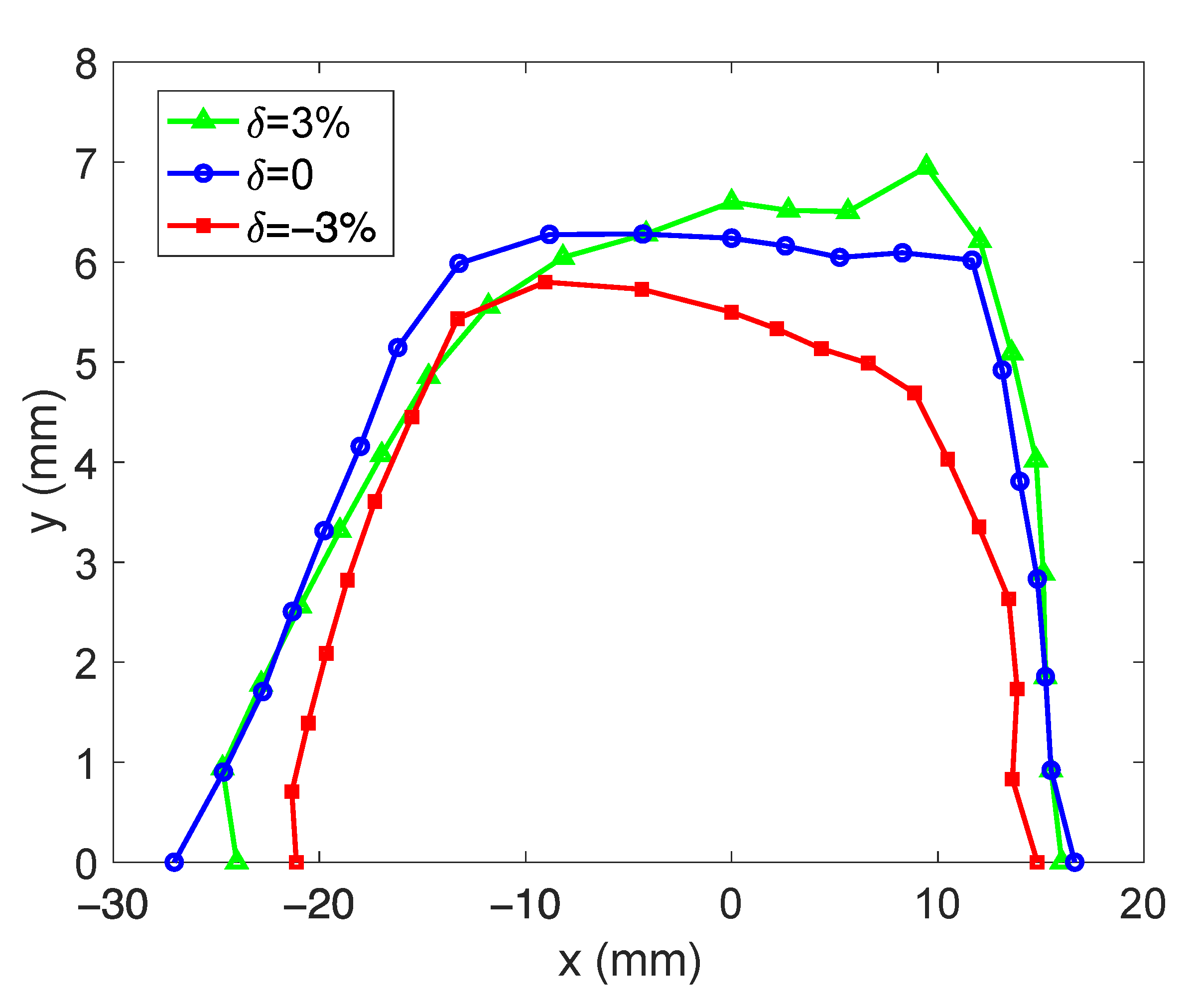
The DDBA lattice employs three families of sextupole magnets, namely SF, SD1, and SD2, for chromaticity correction, and two families of harmonic sextupole magnets, S1 and S2. Octupole magnets are not utilized, resulting in a total of three knobs for nonlinear optimization (SF, SD1 with fixed strength used for chromaticity correction). During optimization, we utilized the OPA code [27] to optimize the resonance driving terms (RDT) while fixing the corrected chromaticity to (1, 1). The optimized solutions were imported into the Elegant code [28] for tracking. Figure 4 shows the on- and off-momentum dynamics aperture (DA) in six dimensions (6D) at the injection point (at the center of LSS), including synchrotron radiation and RF cavity. The 6D DA is large and maintains no significant reduction even for off-momentum, making it highly suitable for off-axis injection.
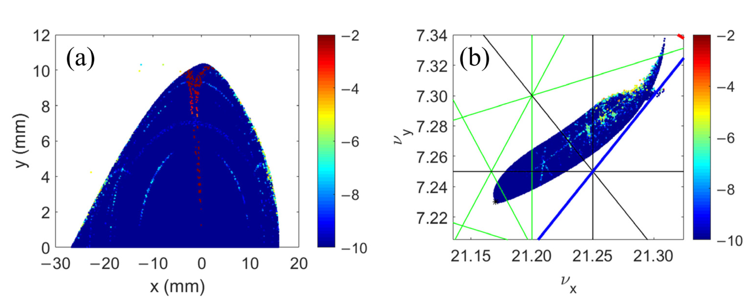
Frequency map analysis (FMA) [29] was employed to analyze the DDBA lattice. FMA is a numerical method based on fine Fourier techniques, which provides a clear representation of the global dynamics of many multidimensional systems. FMA transforms the particle coordinate space (x, y) into the frequency space (νx, νy), where regular motion appears as a fixed point and irregular motion diffuses, manifesting as changes in tunes with the number of turns. The diffusion rate is defined as the following formula:
D r = log 10 ( Δ ν x 2 + Δ ν y 2 N ) ,
where Δνx and Δνy are, respectively, the differences in x and y tunes from the first and second half of the tracking, and N is the number of turns. And a smaller Dr indicates more stable particle motion. Figure 5 displays the results of FMA, where particles were tracked for 1024 turns, and Dr was calculated based on the tunes from the first 512 turns and the last 512 turns. In Figure 5b, resonance lines up to the fifth order are plotted, with the blue lines representing second-order resonances, red lines representing third-order resonances, black lines representing fourth-order resonances, and green lines representing fifth-order resonances. From Figure 5b, it can be found that the particles do not cross any potentially dangerous resonance lines, which indicates that the lattice has good nonlinear dynamics performance.
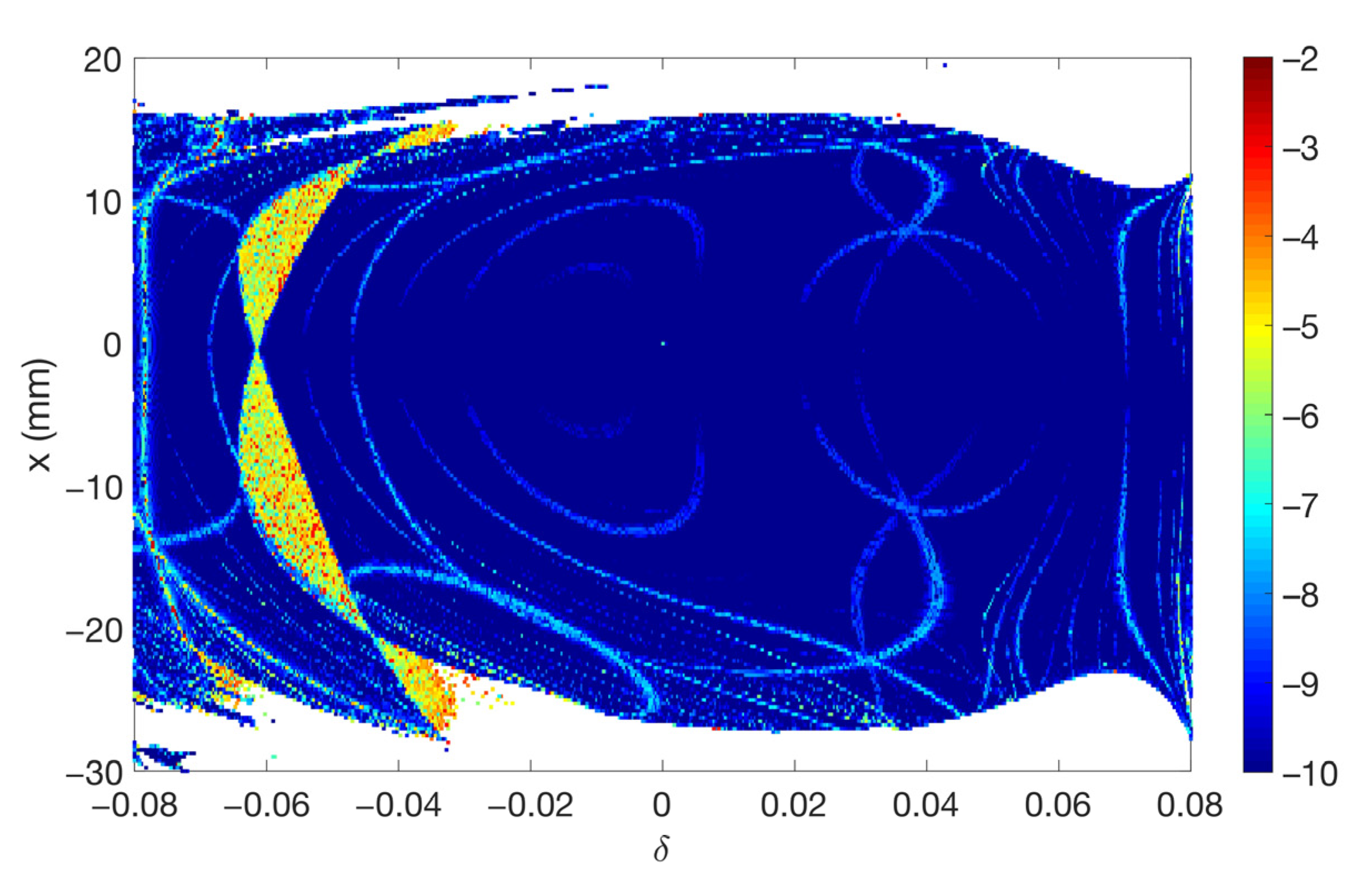
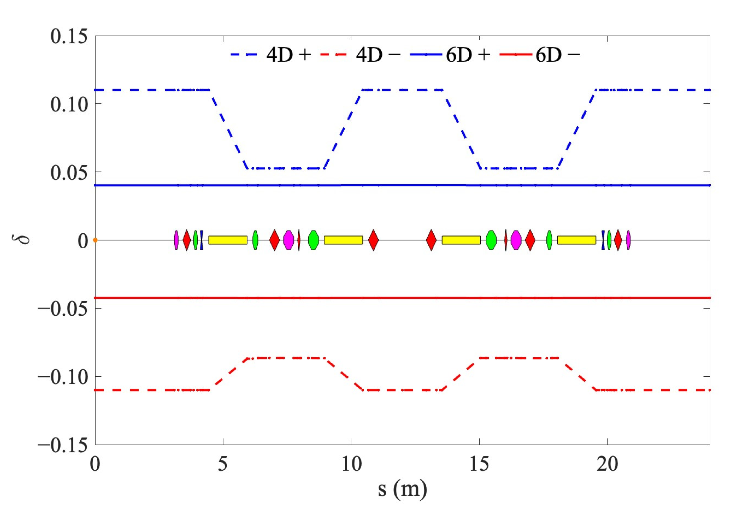
Figure 6 demonstrates the tune shift with momentum deviation ranging from −8% to 8%. It can be seen that the vertical tune of the lattice crosses the half-integer resonance when the momentum deviation approaches −8%. Combined with the FMA results of off-momentum shown in Figure 7, it can be observed that no particle loss occurs when crossing the half-integer resonance [30], indicating that the lattice has good momentum acceptance and excellent off-momentum dynamics. We also performed 4D and 6D tracking for the local momentum aperture (LMA), and the results are presented in Figure 8. It can be seen that the 4D LMA is very large, with a momentum acceptance of approximately 11% at the injection LSS. However, the 6D tracking of the LMA is limited by the RF acceptance, which is approximately 4%. Such a large LMA is very favorable for the beam’s Touschek lifetime [31], and we will discuss the Touschek lifetime of the beam after considering the IBS effect in the next section.

4. Intra-Beam Scattering (IBS) and Touschek Scattering

The IBS effect is caused by small-angle Coulomb scattering between charged particles in a bunch [32,33]. It is generally more severe in MBA lattices due to ultra-low emittance, which leads to a high density of electron bunches. This results in severe IBS effects, subsequently increasing the emittance and energy spread of the beam in its final equilibrium state. To decrease the natural emittance of the storage ring, the MBA lattice usually designs the bending magnets with weak fields. This results in smaller synchrotron radiation losses and longer damping times. The IBS effect is closely related to the damping time, and the longer the damping time, the more severe the IBS effect. For a specific lattice structure, the natural emittance of the beam is proportional to the square of its energy, while the IBS growth rate is inversely proportional to the cube of its energy. Therefore, under the combined effects of IBS, synchrotron radiation damping, and quantum excitation, there exists an optimized energy value at which the equilibrium emittance of the storage ring is minimized.
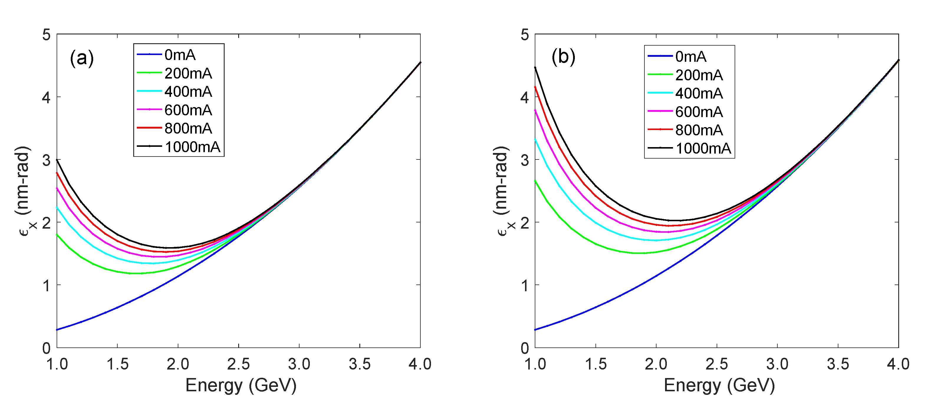
The relationship between beam energy and equilibrium emittance under different beam currents was simulated based on the storage ring parameters presented in Table 1. The IBS effect of this DDBA lattice was simulated in 80% bunch filling mode with 1% and 0.1% transverse coupling, respectively, using the Elegant code to calculate the IBS effect, and the results are shown in Figure 9. As can be seen in Figure 9, the minimum equilibrium emittance of the DDBA lattice occurs at a beam energy of approximately 1.5–2.0 GeV as the beam current increases at the transverse coupling of 1%. At the transverse coupling of 0.1%, the minimum equilibrium emittance of the DDBA lattice occurs at a beam energy of about 1.8–2.2 GeV as the beam current increases. At lower beam energies, the equilibrium emittance is primarily determined by the combined effects of synchrotron radiation damping and IBS effect due to the small horizontal emittance and high IBS growth rate. At higher energies, the equilibrium emittance is primarily determined by quantum excitation and synchrotron radiation damping, which is approximately equal to the natural emittance of the beam at zero beam current. In this paper, we selected a beam energy of 3 GeV because, at this energy, the IBS effect is negligible, and it is suitable for producing hard X-rays. Due to the low magnet strength of this DDBA lattice, the ability to boost the beam energy of this storage ring to 4 GeV is retained for subsequent upgrades.
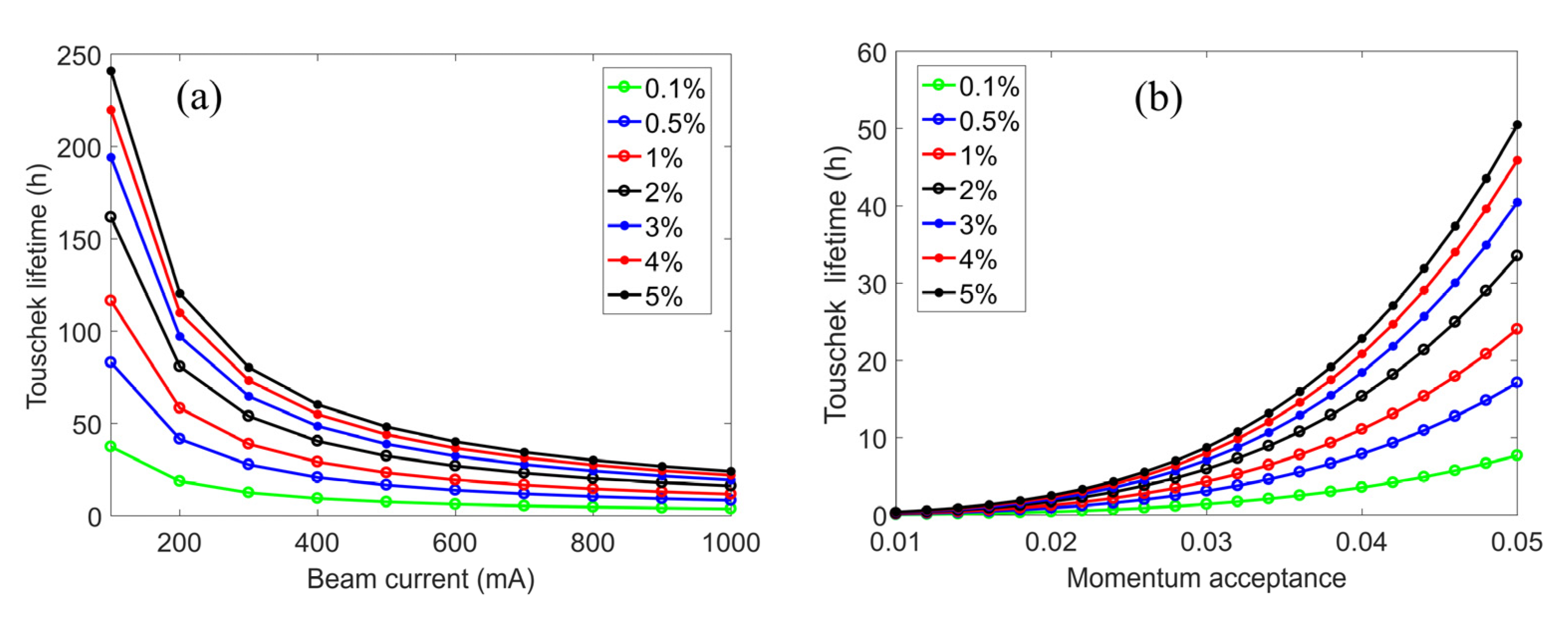
Touschek scattering is a large-angle elastic scattering process between electrons inside a bunch. The Touschek effect is related to IBS, but specifically refers to scattering events that result in a significant transfer of momentum from the transverse to the longitudinal planes. In contrast, IBS refers to multiple small-angle scattering events. If the change in longitudinal momentum is significant, the momentum deviation of one or both electrons may exceed the momentum acceptance of the storage ring, resulting in the loss of electrons from the bunch. In low-emittance storage rings, Touschek scattering is the primary factor that limits beam lifetime. We calculated and analyzed the Touschek lifetime of the beam for various beam currents, transverse couplings, and momentum acceptances, and the findings are presented in Figure 10. For Figure 10a, the momentum acceptance of the storage ring was set to a fixed value of 4.06% in the calculation, which is consistent with the nonlinear dynamics performance of the designed DDBA lattice, as shown in Figure 8. For Figure 10b, the beam current was fixed at 1000 mA in the calculation. The RF acceptance is about 5.26% when the RF voltage is 6.1 MV. We analyze the Touschek lifetime by restricting the maximum value of momentum aperture to 5%, i.e., not more than the minimum value of LMA in Figure 8.
The brilliance of a storage ring light source is proportional to the beam current and inversely proportional to the product of the horizontal and vertical emittances, where the horizontal emittance is determined by the lattice structure and the beam current is limited by instability thresholds. Therefore, third-generation storage ring light sources generally increase the brilliance of the light source by reducing the vertical emittance. However, this approach can decrease the Touschek lifetime of the beam. Magnet alignment and transverse coupling correction can reduce the vertical emittance of the storage ring to the quantum limit [34]. Due to its small horizontal emittance, the DLSR has a very low Touschek lifetime. Therefore, the DLSR is typically operated at full coupling to increase the Touschek lifetime. In this DDBA lattice, with a transverse coupling of only 0.1% and a beam current of 1000 mA, the Touschek lifetime remains at 3.74 h. This is sufficient for Top-up operation, demonstrating that the DDBA lattice can operate at very low transverse coupling. We investigated the Touschek lifetime under larger transverse coupling. At 2% coupling with a beam current of 1000 mA, the Touschek lifetime is about 16.17 h, consistent with that of a general third-generation light source operating under a beam current of about 200 mA. If the DDBA lattice operates at 5% coupling at 1000 mA, its Touschek lifetime is as high as 24.09 h. The DDBA lattice has a high Touschek lifetime in either case.

5. Photon Performance

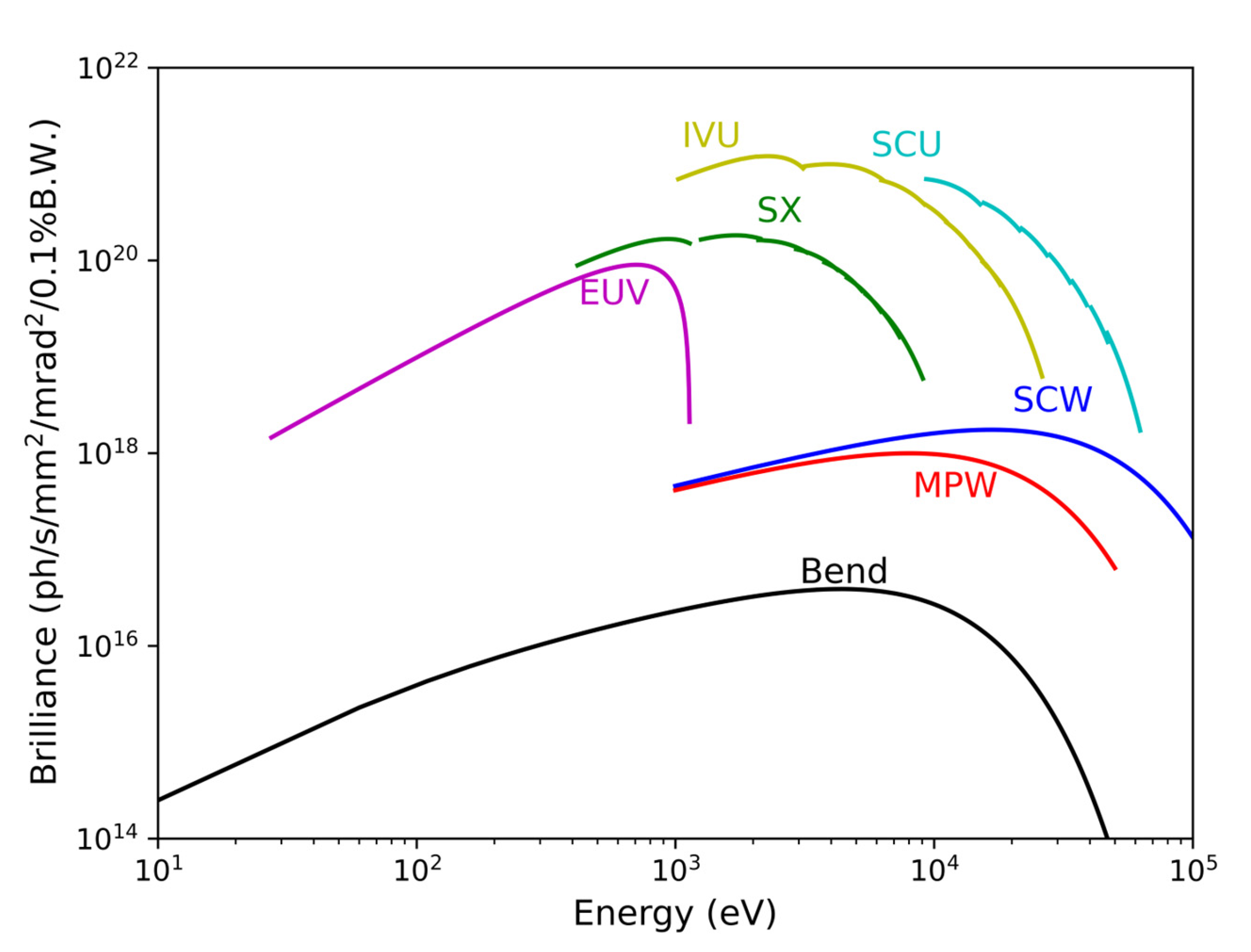
Initially, five types of insertion devices (IDs), which include in-vacuum undulators (IVU), multiple wigglers (MPW), APPLE-II type elliptically polarized undulators (EPUs), superconducting (SC) wigglers, and SC undulators, will be adopted to cover the whole energy range from extreme-ultraviolet (EUV) to hard X-ray. The typical parameters of these IDs are summarized in Table 3. Brilliances of these IDs, calculated using the code SPECTRA [35], are shown in Figure 11. The brilliance of third-generation storage rings is typically in the order of 1020 ph/s/mm2/mrad2/0.1%BW, and the brilliance of the DLSR is normally in the order of 1022 ph/s/mm2/mrad2/0.1%BW. From Figure 11, it can be seen that the design in this paper can reach the 1021 ph/s/mm2/mrad2/0.1%BW, which is between the third-generation storage rings and the DLSRs.

6. Discussions and Conclusions

Most DLSRs, in operation, under construction, or in the planning phase, that adopt a hybrid MBA or HOA MBA structure normally require magnets with very high magnetic field strength. Although stronger focusing can reduce the emittance of the electron beam and thus increase the brilliance of X-rays, it inevitably reduces the aperture of the vacuum chamber, which is not favorable for achieving high current operation. Furthermore, the DA and MA of the MBA lattice are generally small, which poses great challenges to the beam injection and Touschek lifetime.
Based on the emerging DDBA lattice structure, the design of very compact intermediate-energy storage ring light sources to fill the gap between the third-generation and fourth-generation light sources in China is given, to serve as a dedicated X-ray light source for the materials research in SZLab, a newly established research institute in Suzhou, China.
By using advanced insertion device technologies, which include IVU, MPW, APPLE-II type EPUs, SC wigglers, and SC undulators, we are expecting high photon performances to fulfill the diverse requirements of most users from the material science communities, e.g., structural materials, energy materials, information and communication technology materials, and some frontier functional materials, to name a few.

Author Contributions

Conceptualization, C.L. and J.C.; methodology, C.L.; software, C.L. and H.W.; validation, C.L., J.C. and Q.Z.; formal analysis, C.L.; investigation, C.L., H.W. and K.W.; resources, J.C.; data curation, C.L. and H.W.; writing—original draft preparation, C.L.; writing—review and editing, C.L., J.C., H.W., Q.Z. and K.W.; project administration, J.C.; funding acquisition, C.L. and J.C. All authors have read and agreed to the published version of the manuscript.

Funding

This work was supported by the National Natural Science Foundation of China, grant number 12305161 and Suzhou Laboratory Youth Talent Strategic Subject, grant number QN202415.

Institutional Review Board Statement

Not applicable.

Informed Consent Statement

Not applicable.

Data Availability Statement

The data presented in this study are available upon request from the corresponding author.

Acknowledgments

We acknowledge support from the Shanghai Advanced Research Institute and Suzhou Laboratory.

Conflicts of Interest

The authors declare no conflicts of interest.

References

  1. Zhao, Z.T. Storage ring light sources. Rev. Accel. Sci. Technol. 2010, 03, 57. [Google Scholar] [CrossRef]
  2. Einfeld, D.; Plesko, M.; Schaper, J. First multi-bend achromat lattice consideration. Synchrotron Radiat. 2014, 21, 856–861. [Google Scholar] [CrossRef] [PubMed]
  3. Tavares, P.F.; Leemann, S.C.; Sjöström, M.; Andersson, Å. The MAX IV storage ring project. Synchrotron Radiat. 2014, 21, 862–877. [Google Scholar] [CrossRef] [PubMed]
  4. Tavares, P.F.; Dmour, E.A.; Andersson, Å.; Cullinan, F.; Jensen, B.N.; Olsson, D.K.; Sjöström, M.; Tarawneh, H.; Thorin, S.; Vorozhtsov, A. Commissioning and first-year operational results of the MAX IV 3 GeV ring. Synchrotron Radiat. 2018, 25, 1291–1316. [Google Scholar] [CrossRef]
  5. Liu, L.; Milas, N.; Mukai, A.H.; Resende, X.R.; de Sá, F.H. The Sirius project. Synchrotron Radiat. 2014, 21, 904–911. [Google Scholar] [CrossRef]
  6. Raimondi, P.; Benabderrahmane, C.; Berkvens, P.; Biasci, J.C.; Borowiec, P.; Bouteille, J.-F.; Brochard, T.; Brookes, N.B.; Carmignani, N.; Carver, L.R.; et al. The Extremely Brilliant Source storage ring of the European Synchrotron Radiation Facility. Commun. Phys. 2023, 6, 82. [Google Scholar] [CrossRef]
  7. Raimondi, P.; Carmignani, N.; Carver, L.R.; Chavanne, J.; Farvacque, L.; Le Bec, G.; Martin, D.; Liuzzo, S.M.; Perron, T.; White, S. Commissioning of the hybrid multibend achromat lattice at the European Synchrotron Radiation Facility. Phys. Rev. Accel. Beams 2021, 24, 110701. [Google Scholar] [CrossRef]
  8. Borland, M.; Berenc, T.; Sun, Y.; Sajaev, V. Lower emittance lattice for the Advanced Photon Source Upgrade using reverse bending magnets. In Proceedings of the NAPAC2016, Chicago, IL, USA, 9–14 October 2016; pp. 877–880. [Google Scholar]
  9. Jiao, Y.; Xu, G.; Cui, X.H.; Duan, Z.; Guo, Y.Y.; He, P.; Ji, D.H.; Li, J.Y.; Li, X.Y.; Meng, C.; et al. The HEPS project. Synchrotron Radiat. 2018, 25, 1611–1618. [Google Scholar] [CrossRef]
  10. Agapov, I.; Antipov, S.; Bartolini, R.; Brinkmann, R.; Chae, Y.C.; Einfeld, D.; Hellert, T.; Hüening, M.; Jebramcik, M.; Keil, J.; et al. Petra IV storage ring design. In Proceedings of the IPAC2022, Bangkok, Thailand, 12–17 June 2022; pp. 1431–1434. [Google Scholar]
  11. Tanaka, H. Current status of the SPring-8 upgrade project. Synchrotron Radiat. News 2014, 27, 23–26. [Google Scholar] [CrossRef]
  12. Jang, G.S.; Shin, S.; Yoon, M.; Ko, J.; Yoon, Y.D.; Lee, J.; Oh, B.-H. Low emittance lattice design for Korea-4GSR. Nucl. Instrum. Methods Phys. Res. A 2022, 1034, 166779. [Google Scholar] [CrossRef]
  13. Alekou, A.; Bartolini, R.; Bartolini, R.; Carmignani, N.; Walker, R.; Pulampong, T.; Liuzzo, S.M. Study of a double triple bend achromat (DTBA) lattice for a 3 GeV light source. In Proceedings of the IPAC2016, Busan, Republic of Korea, 8–13 May 2016; pp. 2940–2942. [Google Scholar]
  14. Zhao, Y.; Jiao, Y.; Li, Z.; Liu, W.; Wang, S. Improving the MWI threshold of the modified hybrid-7BA lattice design for SAPS. Nucl. Instrum. Methods Phys. Res. A 2023, 1056, 168565. [Google Scholar] [CrossRef]
  15. Kim, J.; Huang, X.; Raimondi, P.; Safranek, J.A.; Song, M.; Tian, K. A hybrid multi-bend achromat lattice design for SSRL-X. In Proceedings of the IPAC2022, Bangkok, Thailand, 12–17 June 2022; pp. 207–209. [Google Scholar]
  16. Loulergue, A.; Blanco-Garcia, O.R.; Blanco-García, O.; Gamelin, A.; Nadji, A.; Tordeux, M.A.; Brunelle, P.; Foosang, W.; Nadolski, L. TDR baseline lattice for SOLEIL II upgrade project. In Proceedings of the IPAC2023, Venice, Italy, 7–12 May 2023; pp. 689–691. [Google Scholar]
  17. Streun, A.; Aiba, M.; Böge, M.; Calzolaio, C.; Ehrlichman, M.; Negrazus, M.; Riemann, B.; Vrankovic, V. Swiss Light Source upgrade lattice design. Phys. Rev. Accel. Beams 2023, 26, 091601. [Google Scholar] [CrossRef]
  18. Karantzoulis, E.; Barletta, W. Aspects of the Elettra 2.0 design. Nucl. Instrum. Methods Phys. Res. A 2019, 927, 70. [Google Scholar] [CrossRef]
  19. Bai, Z.; Feng, G.; He, T.; Li, W.; Li, W.; Liu, G.; Wang, L.; Yang, P.; Zhang, S. Progress on the storage ring physics design of Hefei advanced light facility (HALF). In Proceedings of the IPAC2023, Venice, Italy, 7–12 May 2023; pp. 703–706. [Google Scholar]
  20. Hellert, T.; Steier, C.; Venturini, M. Lattice correction and commissioning simulation of the Advanced Light Source upgrade storage ring. Phys. Rev. Accel. Beams 2022, 25, 110701. [Google Scholar] [CrossRef]
  21. Farvacque, L.; Carmignani, N.; Chavanne, J.; Franchi, A.; Le Bec, G.; Liuzzo, S.; Nash, B.; Perron, T.; Raimondi, P. A low-emittance lattice for the ESRF. In Proceedings of the IPAC2013, Shanghai, China, 12–17 May 2013; pp. 79–81. [Google Scholar]
  22. Verdier, A. Resonance free lattices for A.G. machines. In Proceedings of the PAC1999, New York, NY, USA, 29 March–2 April 1999; pp. 398–400. [Google Scholar]
  23. Cai, Y.; Bane, K.; Hettel, R.; Nosochkov, Y.; Wang, M.-H.; Borland, M. Ultimate storage ring based on fourth-order geometric achromats. Phys. Rev. Accel. Beams 2012, 15, 054002. [Google Scholar] [CrossRef]
  24. Nishimori, N. A new compact 3GeV light source in Japan. In Proceedings of the IPAC2022, Bangkok, Thailand, 12–17 June 2022; pp. 2402–2406. [Google Scholar]
  25. Klysubun, P.; Sudmuang, P.; Pulampong, T.; Chanwattana, T.; Jummunt, S.; Sunwong, P.; Prawanta, S.; Kwankasem, A.; Juntong, N.; Phimsen, T. SPS-II: A 4th generation synchrotron light source in southeast Asia. In Proceedings of the IPAC2022, Bangkok, Thailand, 12–17 June 2022; pp. 764–768. [Google Scholar]
  26. Bartolini, R.; Abraham, C.; Apollonio, M.; Bailey, C.P.; Cox, M.P.; Day, A.; Fielder, R.T.; Hammond, N.P.; Heron, M.T.; Holdsworth, R.; et al. Double-double bend achromat cell upgrade at the Diamond Light Source: From design to commissioning. Phys. Rev. Accel. Beams 2018, 21, 050701. [Google Scholar] [CrossRef]
  27. Project Web Site. Available online: http://ados.web.psi.ch/opa/ (accessed on 20 December 2024).
  28. Borland, M. Elegant: A flexible SDDS-compliant code for accelerator simulation. In Proceedings of the 6th International Computational Accelerator Physics Conference, Darmstadt, Germany, 11–14 September 2000. Advanced Photon Source Report 2000, No. LS-287. [Google Scholar]
  29. Robin, D.; Steier, C. Global dynamics of the advanced light source revealed through experimental frequency map analysis. Phys. Rev. Lett. 2000, 85, 558. [Google Scholar] [CrossRef]
  30. Jiao, Y.; Duan, Z. Statistical analysis of the limitation of half integer resonances on the available momentum acceptance of the High Energy Photon Source. Nucl. Instrum. Methods Phys. Res. A 2017, 841, 97–103. [Google Scholar] [CrossRef]
  31. Nagaokaa, R.; Baneb, K.L.F. Collective effects in a diffraction-limited storage ring. Synchrotron Radiat. 2014, 21, 937–960. [Google Scholar] [CrossRef]
  32. Piwinski, A. Intra-beam-scattering. In Proceedings of the 9th International Conference on High Energy Accelerators, Stanford, CA, USA, 2–7 May 1974; SLAC: Stanford, CA, USA, 1974; pp. 405–409. [Google Scholar]
  33. Bjorken, J.D.; Mtingwa, S.K. Intrabeam scattering. Part. Accel. 1983, 13, 115–143. [Google Scholar]
  34. Dowd, R.; Boland, M.; LeBlanc, G.; Tan, Y.-R.E. Achievement of ultralow emittance coupling in the Australian Synchrotron storage ring. Phys. Rev. Accel. Beams 2011, 14, 012804. [Google Scholar] [CrossRef]
  35. Tanaka, T.; Kitamura, H. SPECTRA: A synchrotron radiation calculation code. Synchrotron Radiat. 2001, 8, 1221–1228. [Google Scholar] [CrossRef] [PubMed]
Figure 1. Schematic diagram of a storage ring light source.
Applsci 15 02541 g001
Figure 2. Schematic diagram of the MBA lattice structure (assuming M = 7, M represents the number of bending magnets in one cell) and dispersion function (green line) trend of (a) hybrid 7BA and (b) HOA 7BA. The blue rectangles in the figure represent the dipoles, the red polygons represent quadrupoles, and the green polygons represent sextupoles.
Applsci 15 02541 g002
Figure 3. Optical functions of one DDBA cell.
Applsci 15 02541 g003
Figure 4. 6D DA of on- and off-momentum at the injection point (at the center of LSS).
Applsci 15 02541 g004
Figure 5. FMA of the optimized DA, tracked for 1024 turns: (a) x-y space, (b) tune space. The color bar represents the diffusion rate. Blue color denotes more regular motion and red color more chaotic.
Applsci 15 02541 g005
Figure 6. Momentum dependent tune shift.
Applsci 15 02541 g006
Figure 7. Off-momentum FMA. The color bar represents the diffusion rate. Blue color denotes more regular motion and red color more chaotic.
Applsci 15 02541 g007
Figure 8. LMA of one cell. The yellow rectangle represents the dipoles, the red and blue shapes represent the quadrupoles, and the magenta and green shapes represent the sextupoles.
Applsci 15 02541 g008
Figure 9. Equilibrium emittance versus beam energy for different beam currents at (a) 1% transverse coupling; (b) 0.1% transverse coupling.
Applsci 15 02541 g009
Figure 10. Touschek lifetime versus beam current for different transverse couplings (a); Touschek lifetime versus momentum acceptance for different transverse couplings (b).
Applsci 15 02541 g010
Figure 11. Brilliance of planned IDs.
Applsci 15 02541 g011
Table 1. Ring parameters.
ParameterValue
Beam energy3 GeV
Circumference288 m
Lattice type12 × DBA
Tunes21.17, 7.23
Horizontal emittance2.57 nm rad
Energy spread8.64 × 10−4
Natural chromaticity−51.60, −30.45
Corrected chromaticity1.0, 1.0
Momentum compaction factor8.23 × 10−4
Energy loss per turn0.625 MeV
Damping partition numbers1.46, 1, 1.54
Damping time6.33 ms, 9.22 ms, 5.97 ms
Long straight section12 × 6.20 m
Short straight section12 × 1.86 m
Twiss at LSS (betax, betay, etax)18.0 m, 3.20 m, 0 m
Twiss at SSS (betax, betay, etax)3.41 m, 2.85 m, 0.065 m
RF frequency 499.654 MHz
Harmonic number480
RF voltage4.0 MV
RF bucket height4.06%
RMS bunch length3.58 mm
Table 2. Specifications of main magnets.
MagnetNameLengthStrengthBore Diameters
Combined dipolesB1.50 m0.87 T, −5.27 T/m-
QuadrupolesQ10.30 m22.37 T/m50 mm
Q20.10 m−7.37 T/m50 mm
Q30.40 m24.33 T/m50 mm
Q40.10 m7.37 T/m50 mm
Q50.40 m22.12 T/m50 mm
SextupolesS10.15 m687.58 T/m256 mm
S20.15 m−824.57 T/m256 mm
SD10.20 m−368.87 T/m256 mm
SF0.40 m430.02 T/m256 mm
SD20.40 m−483.10 T/m256 mm
Table 3. Typical parameters of planed IDs.
ID TypePeriod (mm)Number PeriodsMax B(T)
IVU221901.15
MPW100131.6
Apple-II (EUV)75531.08
Apple-II (SX *)56710.44
SC wiggler48224.2
SC undulator101162.0
* SX: soft X-ray.
Disclaimer/Publisher’s Note: The statements, opinions and data contained in all publications are solely those of the individual author(s) and contributor(s) and not of MDPI and/or the editor(s). MDPI and/or the editor(s) disclaim responsibility for any injury to people or property resulting from any ideas, methods, instructions or products referred to in the content.