Article

Two-Dimensional Topology Optimization of Headtube in Electric Scooter Considering Multiple Loads

Department of Mechanical Engineering, Keimyung University, Daegu 42601, Republic of Korea
*
Author to whom correspondence should be addressed.
Appl. Sci. 2025, 15(5), 2829; https://doi.org/10.3390/app15052829
Submission received: 23 January 2025 / Revised: 3 March 2025 / Accepted: 4 March 2025 / Published: 5 March 2025
(This article belongs to the Special Issue Mechanical Engineering Reliability Optimization Design)

Abstract

:
The safety and structural integrity of electric scooters have gained considerable attention owing to their increasing use in personal mobility and the associated accident rates. This study applied topology optimization to the headtube of an electric scooter, which is a critical component susceptible to structural failure under diverse load conditions. A finite element model was developed to simulate the behavior of the headtube under 16 single-load conditions, followed by optimization for multiple loads. The optimized design demonstrated an enhanced material distribution, balancing the lightweight construction and structural robustness. Collision performance analysis revealed an improvement of at least 51% in the strain energy distribution compared with that of existing commercial models. These results underscore the potential efficacy of topology optimization in enhancing the safety and reliability of personal mobility devices. Moreover, topology optimization can provide a systematic framework for designing critical structural components.

1. Introduction

Electric scooters have become a hallmark of personal mobility and have been rapidly adopted globally. The popularity of electric scooters is driven by their user-friendly operation and the widespread availability of shared services, such as Lime and Alpaca, which considerably increase their accessibility. Additionally, electric scooters contribute to reducing traffic congestion in tourist hotspots. In cities like Paris and Barcelona, electric scooters account for 45–60% of personal mobility [1]. This growing demand has propelled the expansion of the personal mobility industry, including sharing services, at a rate of 10.3%, with market research forecasting significant growth in the future [2,3]. However, their rapid proliferation has been accompanied by a substantial increase in accidents involving these scooters. In South Korea, accident rates have surged by 282%, whereas in the USA, injuries related to electric scooters have tripled from 4583 in 2014 to 14,641 in 2018 [4]. These accidents are often more severe than car accidents because of their direct impact on riders, highlighting the urgent need for improved safety measures.
Efforts to mitigate accidents have focused on enhancing driving regulations and laws to reduce driver-induced accidents. However, these measures do not address accidents caused by scooter malfunctions. Safety concerns are often compromised by designs driven by cost-effectiveness and the desire for lightweight structures at the expense of rigorous safety standards. Despite being preventable, accidents owing to the quality defects of electric scooters persist. Previous studies have attempted to address this issue by improving the structural integrity of scooters through material and design modifications, such as adopting magnesium alloy frames [5,6] and ergonomic designs [7,8,9]. These innovations have improved rigidity and safety while managing lightweight structures. Despite these advancements, design improvements have primarily relied on engineering expertise and designer intuition rather than a systematic design framework.
Design optimization offers a robust solution to the limitations of conventional design methods for electric scooters. Design optimization, known for its systematic, efficient, and automated approach across various engineering fields, surpasses empirical methods by minimizing objective functions (e.g., maximum equivalent stress) while satisfying constraints (e.g., weight limits), even when dealing with multiple design variables. The benefits of design optimization are widely recognized in the automotive [10,11,12,13], maritime [14], healthcare [15,16], robotics [17], construction [18,19], aerospace [20,21], and other fields [22,23,24,25]. Specifically, existing studies in automotive engineering primarily focus on multi-material optimization, whereas robotic engineering research emphasizes the optimization of kinematic flexibility and dynamic stability [26,27,28]. Similarly, topology optimization has been widely applied in the design of automotive and robotic structures. However, research on its application to electric scooters remains limited owing to the unique structural and loading characteristics of personal mobility devices.
Topology optimization is a powerful numerical method that optimizes the material distribution within a design space to maximize performance under specific loads, boundary conditions, and constraints [29]. By systematically removing nonessential material, lightweight and structurally robust designs are produced. However, the effectiveness of topology optimization is highly dependent on the load conditions [30]. For example, a vertical structure optimized for normal loads may struggle to maintain its structural integrity under lateral forces. This highlights the need to incorporate multiple loading scenarios into the optimization process, as most existing studies have focused on singular loading conditions [31], potentially overlooking the diverse forces encountered in real-world applications.
This study aimed to enhance the structural safety of electric scooters by applying topology optimization to the headtube, a known structural weakness, under multiple-load conditions. By adopting this approach, this study aimed to prevent structural failures and improve the overall safety of electric scooters. A representative electric scooter was modeled as a finite element (FE) model, and topology optimization of the headtube was conducted for 16 single-load scenarios. Subsequently, topology optimization was performed by jointly considering multiple-load conditions. Finally, the optimized design was analyzed, and its collision performance was compared with those of two market-leading models.

2. Design Optimization

In this study, the topology optimization of the headtube of an electric scooter is organized into analysis and update stages: an FE analysis-based structural behavior analysis stage, and an analysis-based design variable update stage (Figure 1). Section 2.1 presents the FE modeling for topology optimization. Section 2.2 and Section 2.3 present topology optimization under single and multiple loads, respectively. The corresponding results are also analyzed.

2.1. Pixel-Based FE Modeling of Electric Scooter Headtube

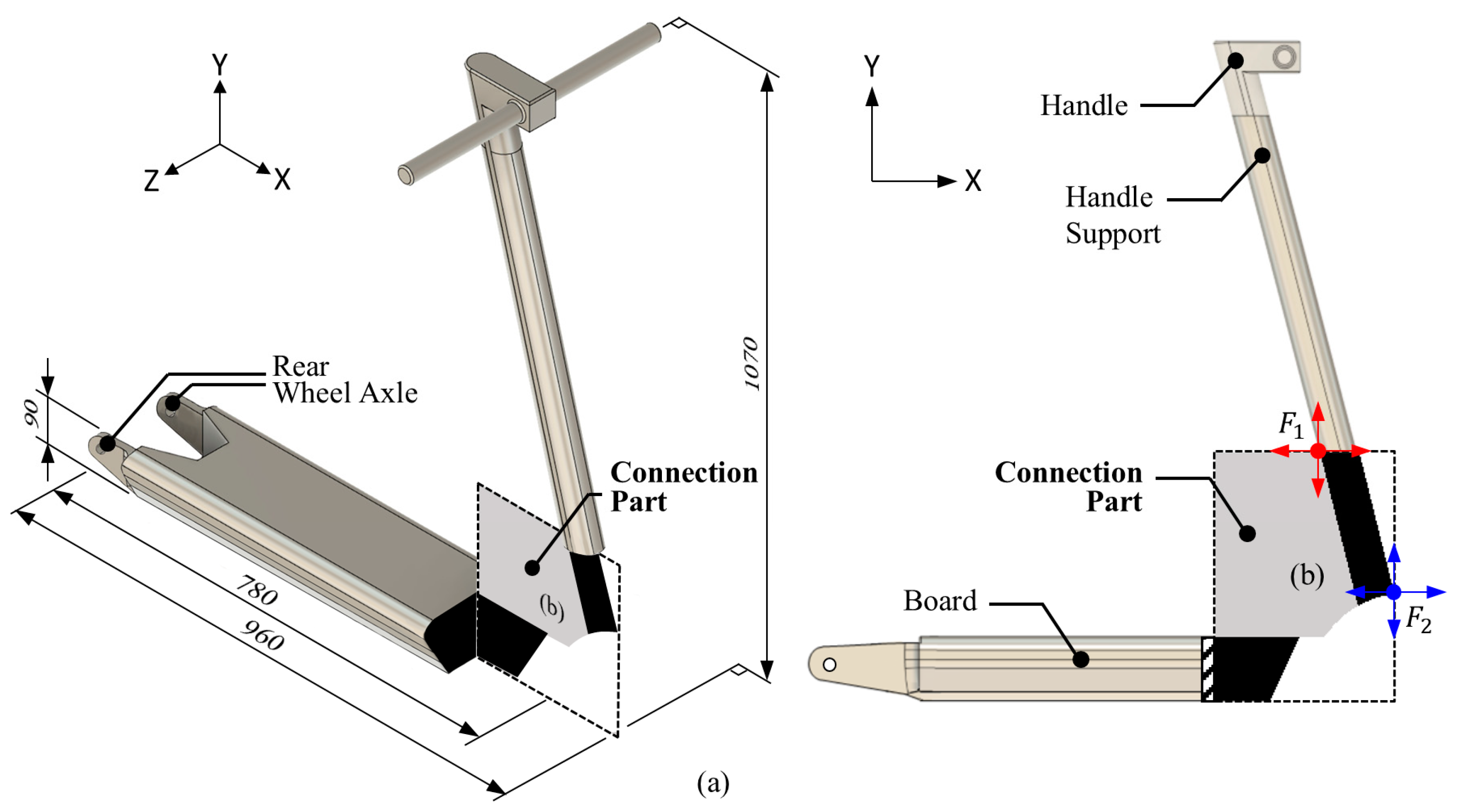
Figure 2a shows the FE model of the headtube of an electric scooter (Ninebot Max G30, Segway Ninebot, Beijing, China). The headtube serves as the connection between the handle support and the deck. To represent the headtube, the design area was modeled as a rectangle measuring 274 mm in length and 350 mm in height (Figure 2b). The maximum density is represented as black pixels in Figure 2a, and hollowness is assigned a minimum density (white pixels). For topology optimization, the headtube connecting the handle support and footrest was designated as the design area, excluding the sections that would interfere with the front wheel. Owing to the scooter’s symmetrical structure, maximum stress during a frontal plane collision occurs along the sagittal (longitudinal) plane. To reflect this characteristic and structural behavior and enhance topology optimization, the 3D shape was simplified into a 2D FE model.
The FE model was built using 23,975 pixel-based bilinear elements, each measuring 2 mm × 2 mm. The pixel- (2D) or voxel- (3D) based approach superimposes a grid of equally sized rectangular elements on the target structure and has been successfully used in computational biomechanics to construct micro-FE models [32,33,34].
The load points were selected at the top-left and bottom-right corners of the handle support, and the applied forces from the user and front wheel were used. All degrees of freedom in all nodes at the left end of the board were restrained. Equation (1) represents the modulus of elasticity of each element obtained by converting the element density based on solid isotropic material penalization. The Poisson ratio of all components was 0.3 [35,36].
E i ρ i = ρ i 3 E 0
where E i is the reference modulus of elasticity of the i -th FE, ρ i is the relative density of the i -th FE, and E 0 (equal to 1) is the modulus of elasticity when the relative density is 1.

2.2. Topology Optimization: Single-Load Conditions

Methodology

Topology optimization iteratively redistributes materials in the design domain to determine the optimal material arrangement. The control mechanism is a self-enhancing system in which more loads attract a larger mass. The update scheme in topology optimization adds material to parts with relatively high strain energy and removes material from parts with relatively low strain energy.
Single-load conditions were applied to the nodes of the structure as concentrated forces, combining each of the four directions at two load points. The design variable was the density of each element. For topology optimization, the total strain energy under each of the 16 load conditions was selected as the objective function to be minimized, and the perimeter constraint volume fraction was implemented. Topology optimization [37] is formulated as follows:
min ρ f ( ρ ) = i = 1 N ( ρ i ) 3 u i T k 0 u i subject to g ( ρ ) = i = 1 N ρ i V 0 = VF 0.001 ρ i 1
where ρ i is the density of each element as a design variable, N is the total number of elements, u i is the displacement vector, k 0 is the stiffness matrix of the elements, V 0 is the volume of the total design area, and V F is the volume fraction. The volume fraction (0.2) and filter size (4 pixels) were applied as hyperparameters. To reduce numerical instabilities in topology optimization, the sensitivity was filtered [38,39] as follows:
f ^ ρ i = 1 ρ i j = 1 N r min d i s t ( i , j ) j = 1 N r min d i s t ( i , j ) ρ j f ρ j
where d i s t ( i , j ) represents the distance between the centers of the i -th and j -th elements and j denotes an element satisfying the condition of d i s t i , j r m i n , where r m i n is the filter size. The design completion criteria are defined by the maximum allowable tolerance of the design variables between iterations. Topology optimization was performed using the Optimality Criteria Method [40], which can be formulated as
ρ i n e w = max ( ρ min , ρ i m ) if ρ i B i η max ( ρ min , ρ i m ) ρ i B i η if max ( ρ min , ρ i m ) < ρ i B i η < min ( 1 , ρ i + m ) min ( 1 , ρ i + m ) if min ( 1 , ρ i + m ) ρ i B i η
where m is the positive move limit, and η is the numerical damping coefficient, set to 0.5.
The optimality condition for updating the design variable is derived from the method introduced by Bendsøe [37] and later refined by Sigmund [34] for topology optimization, as follows: The design variable B i , which is determined from the optimality condition, is given by Equation (5):
B i = p ( ρ i ) p 1 u i T k 0 u i λ V ρ i
where λ is the Lagrangian multiplier, determined using the bi-sectioning algorithm, and the denominator represents the sensitivity of the objective function. Topology optimization was initially performed under 16 single-load conditions to evaluate the structural response of the headtube under various force applications. However, as electric scooters experience complex and varying loads during operation, it was necessary to extend the optimization framework to consider multiple loading conditions. To achieve this, representative load cases were selected based on the observed structural behavior patterns, ensuring that the multiple-load optimization accounted for realistic force interactions while maintaining computational efficiency.

2.3. Topology Optimization: Multiple-Load Condition

Methodology

Enhancing the driving safety of electric scooters through topology optimization requires considering diverse loading conditions. To address this, topology optimization was performed under four representative load conditions (Figure 3). By incorporating multiple loads, the proposed method enables the development of structurally optimized and complex headtube designs.
The design variables and parameters remained consistent with those described in Section 2.2. Four load conditions were selected to represent each group, and the results of the 16 load conditions were summarized. Topology optimization considering multiple loads is formulated as follows:
min ρ f ( ρ ) = k = 1 M i = 1 N c k ( ρ i ) 3 u i ( k ) T k 0 u i ( k ) ,
where c k is a normalized weighting factor for the k -th load condition ( c 1 4 = 0.25 ) and M is the total number of load conditions.

3. Numerical Validation: Comparison of Collision Performance

Methodology

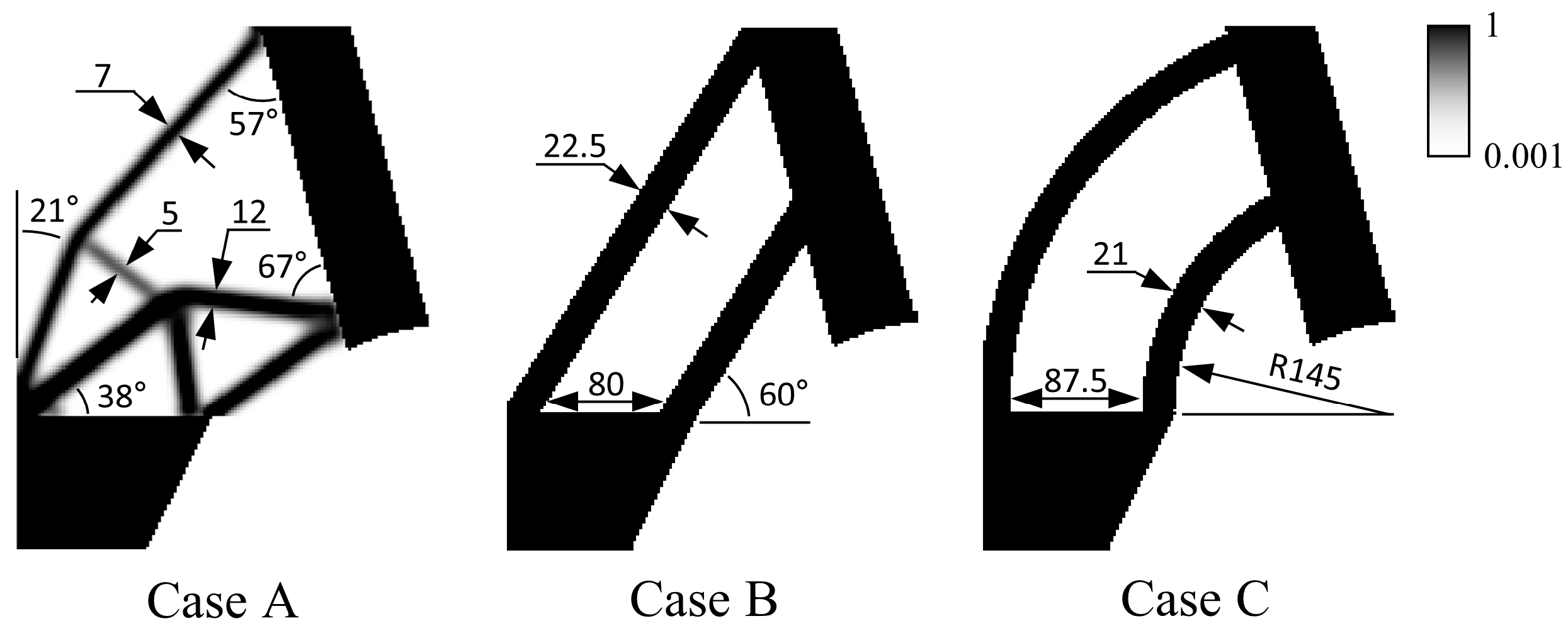
To evaluate the effectiveness of topology optimization under multiple loads, a collision performance comparison was conducted using two commercially available models. The cubic headtube of the Ninebot MAX (Segway Ninebot, Beijing, China) and toroid headtube of Minimoters Dualtron Eagle (Minimotors, Busan, Korea) were selected for comparison (Figure 4). Each model was analyzed under identical boundary conditions, four representative load conditions, and multiple-load scenarios.
A 2D FE analysis was performed under a plane stress condition using an in-house MATLAB R2022a code. This program was selected for its ability to handle large-scale optimization problems involving 23,975 design variables. All calculations were performed on an HP workstation OMEN 40 L (Intel(R) Core™ i9-12900K, 3.20 GHz, 64 GB, Santa Clara, CA, USA). The optimization process converged in approximately 215 iterations with a total computation time of 6 h.

4. Results

4.1. Topology Optimization for Single-Load Conditions

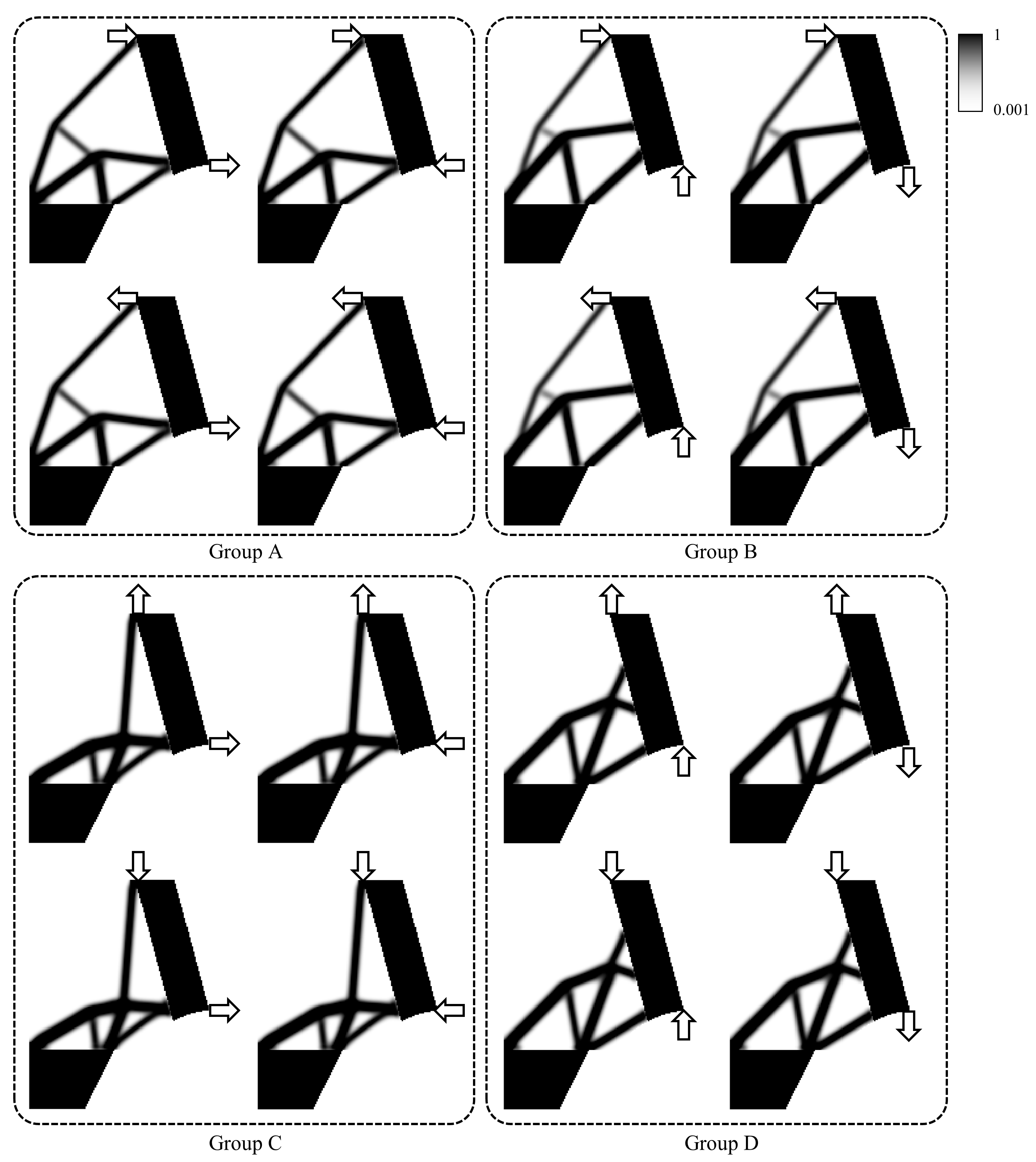
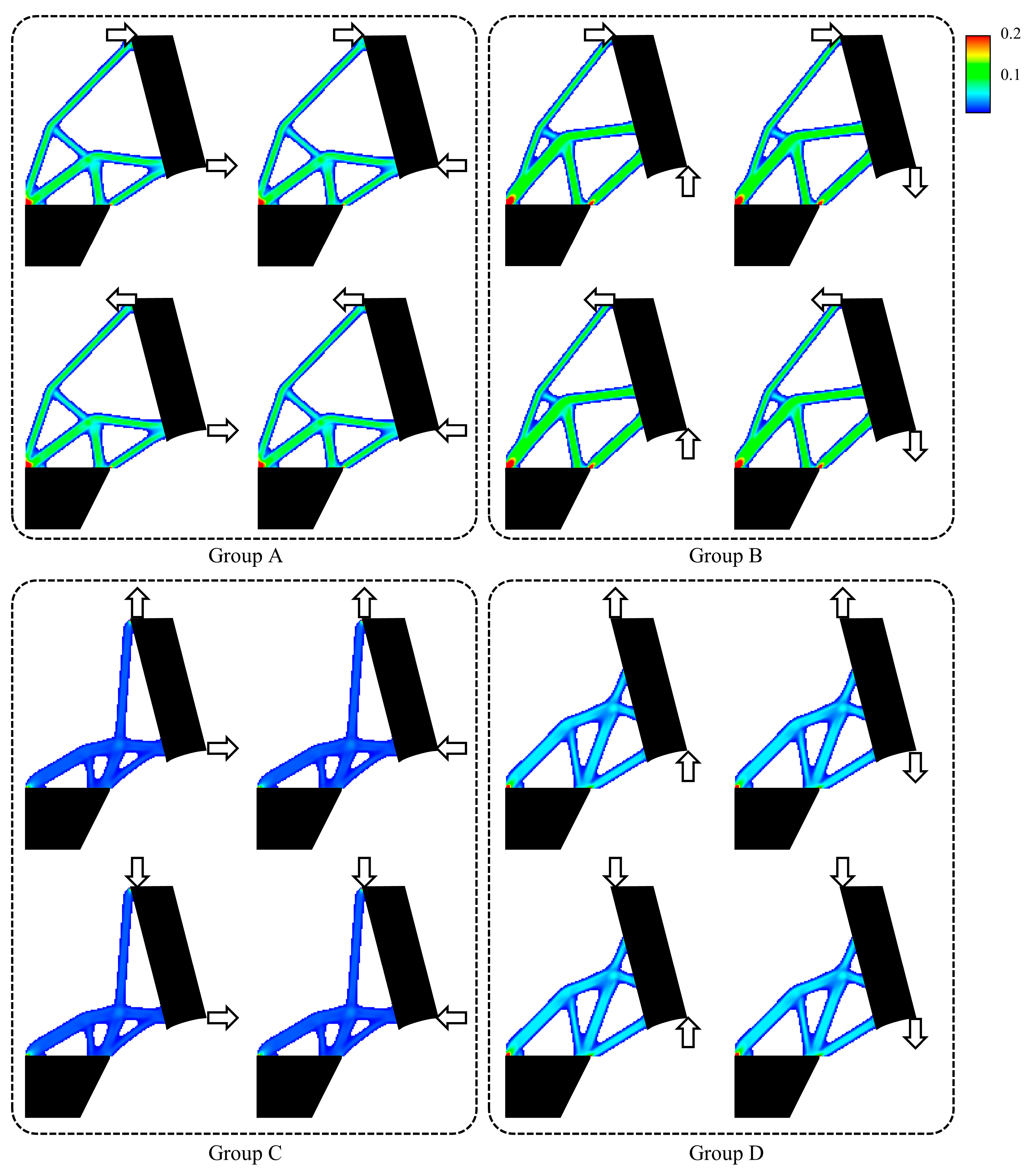
Figure 5 shows the topology optimization results of the headtube according to the loads applied to the handle-supported part of the electric scooter. The results indicate that the 16 load conditions can be divided into four groups according to the axis (X, Y) along which the load is applied. Figure 6 shows the strain energy distribution of the topology optimization results. Within each group, the compliance values of the design domain and the strain energy of each element remain the same.
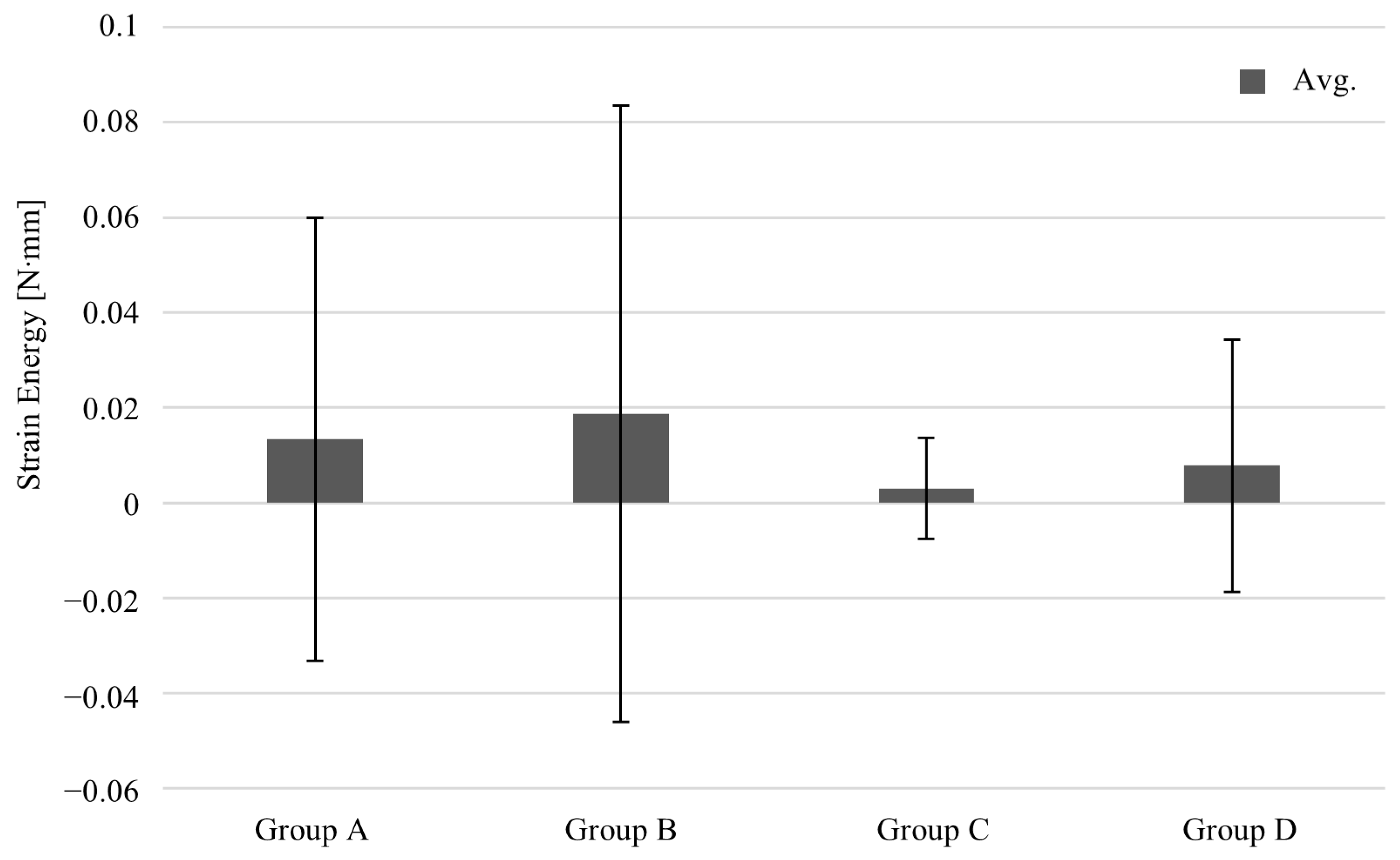
Topology optimization under 16 single-load conditions showed that the loads were divided into four groups. This classification indicates that the various loading conditions experienced while driving an electric scooter can be summarized into four types. The final optimization used multiple loads from Groups A–D (Table 1), ensuring that all potential collision scenarios were considered. As a result, Group C showed the lowest mean and standard deviation of strain energy (Figure 7).
As shown in Figure 6, Group C exhibits the lowest compliance. This result is attributed to the distance between the fixed nodes and the axis on which the load is applied (the displacement boundary condition given to the nodes of the backboard is a fixed support that restrains both rotation and translation, not a frictionless support). The distance from the fixed support to the axis on which the load is applied increases the stress. This phenomenon can be explained by the positioning of the fixed nodes at the rear of the scooter, with the load application axis located close by. Consequently, Group C achieves the lowest compliance owing to the minimal distance between the applied load axis and the fixed support.

4.2. Topology Optimization for Multiple-Load Conditions

Figure 8 shows the comparison of the targets and results of topology optimization considering multiple loads. Overall, the optimized result is similar to the structure of Groups A and B. However, the upper structure of the headtube appears to tilt forward due to the influence of Group B. Notably, the connection points of the board and handle support remain unchanged from Group A, indicating that this location is likely the optimal design for the headtube.
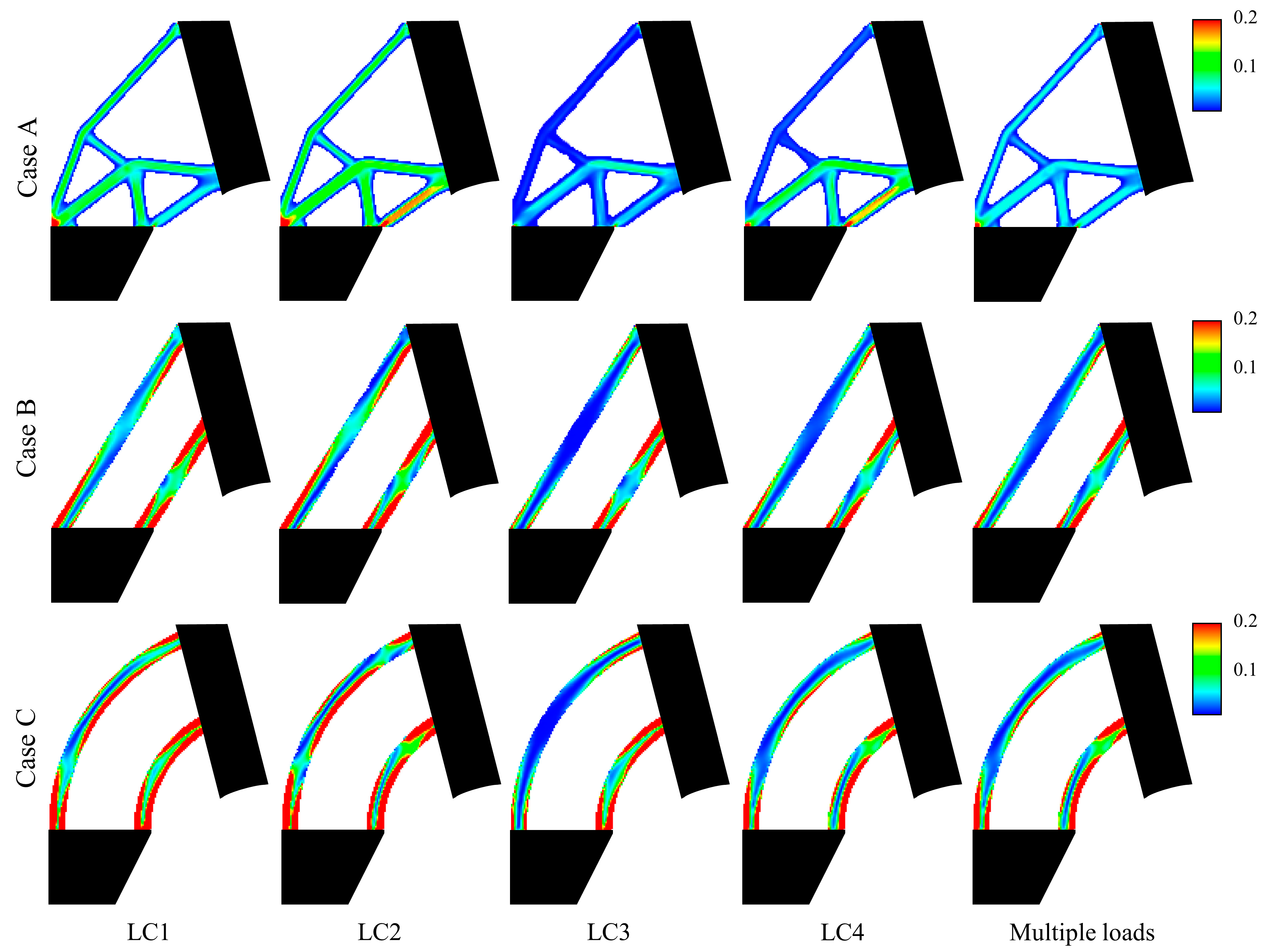
The strain energy distributions in the comparison targets and optimized results were compared under five load conditions (four single-load conditions and multiple loads). As shown in Figure 9, the comparison target models (Cases B and C) exhibit nonuniform strain energy distributions over the entire domain. Conversely, as shown in Figure 10, the topology optimization result (Case A) exhibits a more uniform strain energy distribution in the connection area than the other cases. This quantitatively confirms that the optimized design distributes strain energy more evenly compared to the comparison models (Cases B and C). Furthermore, the optimized design (Case A) demonstrated at least a 51% improvement in collision performance compared to the commercial models (Table 2). Additionally, the optimized design reduces compliance by distributing the strain energy evenly throughout the structure (standard deviation of 0.0155–0.0673 N·mm). However, the comparison commercial models exhibited strain energy concentration with standard deviations between 0.0752 and 0.3546 N·mm. Positioning the headtube closer to the front wheel increases the strain, intensifying the energy concentration within the structure.

5. Discussion

This study successfully demonstrates how single-load topology optimization can be extended to multiple-load conditions to achieve an optimal structural configuration. The results indicate that the optimized structure integrates key features from different load cases, resulting in a more robust and efficient design.
The final optimized structure closely resembles the configurations of Groups A and B, confirming that topology optimization effectively generates optimal designs for complex structures subjected to multiple loads. Unlike designs strictly derived from a single-load condition, the optimized configuration integrates structural features from multiple groups, particularly Groups A and B, to accommodate multidirectional and multi-axial loads. This adaptability highlights the robustness of topology optimization in addressing varying load conditions, offering valuable insights for future structural developments and providing a deeper understanding of topology optimization under diverse loading scenarios.
Additionally, the optimized design improves the load distribution, reducing the strain energy concentration and enhancing the overall performance. Specifically, the topology optimization result (Case A) exhibits a more uniform strain energy distribution than the comparison commercial models. This aligns with established structural optimization theories, which suggest that an ideal optimized structure evenly distributes stress and utilizes all parts of the structure efficiently. Moreover, the optimized headtube was also analyzed in terms of its behavior under each of the four load conditions. Figure 9 shows that the individual load could not achieve a uniform strain energy distribution in the Case A structure. However, the results of Case A, considering all three loads, indicate a more uniform strain energy distribution. This means that the topology optimization structure is designed to cope with complex multidirectional and multiaxial loads when driving an electric scooter, not a design optimized for a single load. This result is consistent with the findings of Jang et al. [14], who determined that the strain energy distribution of trabecular architecture becomes more uniform during optimization to support various daily activities.
Existing electric scooters are simple in structure and easy to manufacture but are not designed to consider the various load conditions that can occur while driving. Therefore, it should be emphasized that topology optimization results considering multiple loads are safer than those of existing commercial models. Table 2 clearly shows that the collision performance of the optimized design increased by at least 51% compared with that of the existing commercial models. Overall, topology optimization appears to be promising for improving the driving safety of electric scooters.
Although the optimized headtube design demonstrates a more uniform strain energy distribution, localized stress concentrations may still occur owing to two main factors. First, while the optimized headtube design demonstrates a more uniform strain energy distribution, certain regions may still experience localized stress concentrations owing to geometric transitions, material redistribution, and external loading conditions. One critical area is the steering column–headtube junction, which is subject to torsional loads from steering and lateral impacts. In this region, sudden material changes can cause localized stress amplification. Second, another potential stress concentration area is the lower fork connection point, where the braking forces and front-wheel impact loads are directly transferred to the headtube. This region experiences high compressive and shear stresses, which can lead to premature fatigue failure if not correctly designed.
Although topology optimization design has been successfully performed under multiple loading conditions, some limitations and additional work are required to apply this methodology to real-world problems. First, in the modeling stage, the design of the electric scooter was simplified, and detailed structures were excluded. Consequently, while the optimization results may differ from the actual model, the design simplification significantly reduced the analysis time. Second, topology optimization was performed by assuming plane stress and two dimensions. However, owing to its symmetrical structure, an electric scooter is subjected to maximum stress in the longitudinal or sagittal plane. Nevertheless, previous studies have demonstrated the effectiveness of sagittal plane-based assessment methods in healthcare applications [41,42].
A major challenge in this study was demonstrating the feasibility of the proposed design using topology optimization considering multiple loads. Even though several researchers have used larger FE models than the model in this study, their objective was to determine a lightweight design. Conversely, this study performed topology optimization to improve the driving safety of electric scooters. Other important aspects are the large array size required for optimization and the additional computational cost incurred owing to the management of the arrays in the optimization algorithm. A 3D analysis with an equivalent resolution will require preparing and managing thousands of design variables. Therefore, the efficiency of topology optimization should be improved in future work.

6. Conclusions

This study proposed a design for the headtube of an electric scooter to improve driving safety using topology optimization. Conventional electric scooter designs emphasize material changes or ergonomic adjustments to enhance the riding comfort. In contrast, the proposed approach leverages topology optimization under multiple loading conditions, resulting in a structurally optimized headtube with enhanced stiffness and impact resistance. The headtube structure was reconstructed by applying compliance minimization optimization to achieve an optimal structure, effectively reducing the strain energy. The results demonstrate that the optimized design achieves at least a 51% improvement in collision performance compared to conventional commercial models, highlighting the practical benefits of topology optimization in real-world applications. These findings emphasize the importance of considering multiple loads in the design process, as this leads to a more reliable and safer structure capable of withstanding complex impact scenarios. Future research should explore complete 3D topology optimization, fatigue analysis, and material constraints to refine the structural performance and manufacturability of optimized electric scooter components.

Author Contributions

Conceptualization, M.G.K. and J.J.K.; methodology, M.G.K. and J.W.C.; software, M.G.K. and J.W.C.; validation, M.G.K. and J.J.K.; formal analysis, M.G.K. and J.W.C.; investigation, M.G.K. and J.W.C.; resources, J.J.K.; data curation, J.J.K.; writing—original draft preparation, M.G.K. and J.W.C.; writing—review and editing, J.W.C. and J.J.K.; visualization, J.W.C. and J.J.K.; supervision, J.J.K.; project administration, J.J.K.; funding acquisition, J.J.K.; All authors have read and agreed to the published version of the manuscript.

Funding

This paper was supported by the Korea Institute for Advancement of Technology (KIAT) grant funded by the Korea Government (MOTIE). (P0020536, HRD Program for Industrial Innovation).

Institutional Review Board Statement

Not applicable.

Informed Consent Statement

Not applicable.

Data Availability Statement

The original contributions presented in the study are included in the article, further inquiries can be directed to the corresponding author.

Acknowledgments

The authors would like to thank the technical support from Ansys Korea.

Conflicts of Interest

The authors declare no conflicts of interest.

References

  1. Zagorskas, J.; Burinskiene, M. Challenges Caused by Increased Use of E-Powered Personal Mobility Vehicles in European Cities. Sustainability 2020, 12, 273. [Google Scholar] [CrossRef]
  2. Kim, Y.W.; Park, W.B.; Cho, J.S.; Hyun, S.Y.; Lee, G. The New Recreational Transportation on the Street: Personal Mobility, Is It Safe? J. Trauma Inj. 2018, 31, 125–134. [Google Scholar] [CrossRef]
  3. Jang, Y.; Ku, D.; Lee, S. Environmental Benefit Calculation on Personal Mobility. Chem. Eng. Trans. 2021, 89, 289–294. [Google Scholar] [CrossRef]
  4. Oh, J.; Kim, J. Where to Ride? An Explorative Study to Investigate Potential Risk Factors of Personal Mobility Accidents. Int. J. Environ. Res. Public Health 2021, 18, 965. [Google Scholar] [CrossRef]
  5. Dong, H.B.; Zhang, W. Lightweight Design of Electric Scooter Frame by Finite Element Optimization. Adv. Mater. Res. 2011, 201–203, 49–53. [Google Scholar] [CrossRef]
  6. Mesicek, J.; Jancar, L.; Ma, Q.-P.; Hajnys, J.; Tanski, T.; Krpec, P.; Pagac, M. Comprehensive View of Topological Optimization Scooter Frame Design and Manufacturing. Symmetry 2021, 13, 1201. [Google Scholar] [CrossRef]
  7. Chou, J.-R.; Hsiao, S.-W. An Anthropometric Measurement for Developing an Electric Scooter. Int. J. Ind. Ergon. 2005, 35, 1047–1063. [Google Scholar] [CrossRef]
  8. Hsia, S.Y.; Chou, Y.T. Analysis of Welding Fatigue on Electric Scooter Using CAE Approach. Appl. Mech. Mater. 2013, 291–294, 920–924. [Google Scholar] [CrossRef]
  9. Shivhare, G.; Kundu, K.; Narayan, J.; Dwivedy, S.K. Design and Modeling of a Compact Lightweight Electric-Scooter. In Proceedings of the 2021 International Conference on Computational Performance Evaluation (ComPE), Shillong, India, 1–3 December 2021; IEEE: Piscataway, NJ, USA, 2021; pp. 944–949. [Google Scholar]
  10. Yang, R.J.; Chahande, A.I. Automotive Applications of Topology Optimization. Struct. Optim. 1995, 9, 245–249. [Google Scholar] [CrossRef]
  11. Jang, G.-W.; Yoon, M.-S.; Park, J.H. Lightweight Flatbed Trailer Design by Using Topology and Thickness Optimization. Struct. Multidiscip. Optim. 2010, 41, 295–307. [Google Scholar] [CrossRef]
  12. Kumagai, M.; Otomori, M.; Ide, T.; Yamada, T.; Izui, K.; Nishiwaki, S. Design Study of Lightweight Automatic Transmission Parts for Vehicles Using Level Set-Based Topology Optimization. In SAE Technical Papers; SAE International: Warrendale, PA, USA, 2016. [Google Scholar]
  13. Tyflopoulos, E.; Lien, M.; Steinert, M. Optimization of Brake Calipers Using Topology Optimization for Additive Manufacturing. Appl. Sci. 2021, 11, 1437. [Google Scholar] [CrossRef]
  14. Jang, I.G.; Kim, K.-S.; Kwak, B.M. Conceptual and Basic Designs of the Mobile Harbor Crane Based on Topology and Shape Optimization. Struct. Multidiscip. Optim. 2014, 50, 505–515. [Google Scholar] [CrossRef]
  15. Jang, I.G.; Kim, I.Y. Computational Study of Wolff’s Law with Trabecular Architecture in the Human Proximal Femur Using Topology Optimization. J. Biomech. 2008, 41, 2353–2361. [Google Scholar] [CrossRef] [PubMed]
  16. Kim, J.J.; Jang, I.G. Image Resolution Enhancement for Healthy Weight-Bearing Bones Based on Topology Optimization. J. Biomech. 2016, 49, 3035–3040. [Google Scholar] [CrossRef] [PubMed]
  17. Briot, S.; Goldsztejn, A. Topology Optimization of Industrial Robots: Application to a Five-Bar Mechanism. Mech. Mach. Theory 2018, 120, 30–56. [Google Scholar] [CrossRef]
  18. Beghini, L.L.; Beghini, A.; Katz, N.; Baker, W.F.; Paulino, G.H. Connecting Architecture and Engineering through Structural Topology Optimization. Eng. Struct. 2014, 59, 716–726. [Google Scholar] [CrossRef]
  19. Baandrup, M.; Sigmund, O.; Polk, H.; Aage, N. Closing the Gap towards Super-Long Suspension Bridges Using Computational Morphogenesis. Nat. Commun. 2020, 11, 2735. [Google Scholar] [CrossRef]
  20. Zhu, J.-H.; Zhang, W.-H.; Xia, L. Topology Optimization in Aircraft and Aerospace Structures Design. Arch. Comput. Methods Eng. 2016, 23, 595–622. [Google Scholar] [CrossRef]
  21. Wang, J.; Zhu, J.; Hou, J.; Wang, C.; Zhang, W. Lightweight Design of a Bolt-Flange Sealing Structure Based on Topology Optimization. Struct. Multidiscip. Optim. 2020, 62, 3413–3428. [Google Scholar] [CrossRef]
  22. Yu, Y.; Jang, I.G.; Kwak, B.M. Topology Optimization for a Frequency Response and Its Application to a Violin Bridge. Struct. Multidiscip. Optim. 2013, 48, 627–636. [Google Scholar] [CrossRef]
  23. Tian, Y.; Liu, X.; Xu, Q.; Luo, Q.; Zheng, H.; Song, C.; Zhu, Z.; Gao, K.; Dang, C.; Wang, H.; et al. Bionic Topology Optimization of Fins for Rapid Latent Heat Thermal Energy Storage. Appl. Therm. Eng. 2021, 194, 117104. [Google Scholar] [CrossRef]
  24. Chen, Y.; Meng, F.; Huang, X. Creating Acoustic Topological Insulators through Topology Optimization. Mech. Syst. Signal Process. 2021, 146, 107054. [Google Scholar] [CrossRef]
  25. Rezaei, S.; Kadkhodapour, J.; Hamzehei, R.; Taherkhani, B.; Anaraki, A.P.; Dariushi, S. Design and Modeling of the 2D Auxetic Metamaterials with Hyperelastic Properties Using Topology Optimization Approach. Photonics Nanostructures—Fundam. Appl. 2021, 43, 100868. [Google Scholar] [CrossRef]
  26. Chen, X.; Yang, L.; Gong, Y.; Liu, K. Lightweight design of multi-material body structure based on material selection method and implicit parametric modeling. Proc. Inst. Mech. Eng. Part D J. Automob. Eng. 2024, 16, 22–34. [Google Scholar] [CrossRef]
  27. Sun, J.; Hu, H. Dynamic Topology Optimization of Flexible Multibody Systems. Nonlinear Dyn. 2024, 112, 11711–11743. [Google Scholar] [CrossRef]
  28. Yao, P.; Zhou, K.; Lin, Y.; Tang, Y. Light-Weight Topological Optimization for Upper Arm of an Industrial Welding Robot. Metals 2019, 9, 1020. [Google Scholar] [CrossRef]
  29. Nozawa, S.; Serhat, G. Topology and Fiber Path Optimization of Composite Structures: A Critical Review. Mater. Des. 2025, 251, 113699. [Google Scholar] [CrossRef]
  30. Huang, D.; Zhou, S.; Yan, X. Multi-objective topology optimization design of thermal-mechanical coupling structure based on FPTO method. Optim. Eng. 2024, 26, 53–81. [Google Scholar] [CrossRef]
  31. Kim, M.G.; Kim, J.S.; Kim, J.J. 2-D Topology Optimization of the Connection Part of the Electric Kickboard in Case of Front Collision. J. Korean Soc. Precis. Eng. 2022, 39, 841–848. [Google Scholar] [CrossRef]
  32. Verhulp, E.; van Rietbergen, B.; Huiskes, R. Comparison of Micro-Level and Continuum-Level Voxel Models of the Proximal Femur. J. Biomech. 2006, 39, 2951–2957. [Google Scholar] [CrossRef]
  33. Van Rietbergen, B.; Huiskes, R.; Eckstein, F.; Rüegsegger, P. Trabecular Bone Tissue Strains in the Healthy and Osteoporotic Human Femur. J. Bone Miner. Res. 2003, 18, 1781–1788. [Google Scholar] [CrossRef] [PubMed]
  34. Van Rietbergen, B.; Müller, R.; Ulrich, D.; Rüegsegger, P.; Huiskes, R. Tissue Stresses and Strain in Trabeculae of a Canine Proximal Femur Can Be Quantified from Computer Reconstructions. J. Biomech. 1999, 32, 165–173. [Google Scholar] [CrossRef] [PubMed]
  35. Bendsøe, M.P. Optimal Shape Design as a Material Distribution Problem. Struct. Optim. 1989, 1, 193–202. [Google Scholar] [CrossRef]
  36. Rozvany, G.I.N.; Zhou, M.; Birker, T. Generalized Shape Optimization without Homogenization. Struct. Optim. 1992, 4, 250–252. [Google Scholar] [CrossRef]
  37. Sigmund, O. A 99 Line Topology Optimization Code Written in Matlab. Struct. Multidiscip. Optim. 2001, 21, 120–127. [Google Scholar] [CrossRef]
  38. Sigmund, O. Design of Material Structures Using Topology Optimization. Doctoral Dissertation, Technical University of Denmark, Kongens Lyngby, Denmark, 1994. [Google Scholar]
  39. Sigmund, O. On the Design of Compliant Mechanisms Using Topology Optimization. Mech. Struct. Mach. 1997, 25, 493–524. [Google Scholar] [CrossRef]
  40. Bendsøe, M.P. Optimization of Structural Topology, Shape, and Material; Springer: Berlin/Heidelberg, Germany, 1995; ISBN 978-3-662-03117-9. [Google Scholar]
  41. Prima, S.; Ourselin, S.; Ayache, N. Computation of the Mid-Sagittal Plane in 3-D Brain Images. IEEE Trans. Med. Imaging 2002, 21, 122–138. [Google Scholar] [CrossRef]
  42. Yoon, C.H.; Kim, H.S.; Ju, J.H.; Jee, W.H.; Park, S.H.; Kim, H.Y. Validity of the Sonographic Longitudinal Sagittal Image for Assessment of the Cartilage Thickness in the Knee Osteoarthritis. Clin. Rheumatol. 2008, 27, 1507–1516. [Google Scholar] [CrossRef]
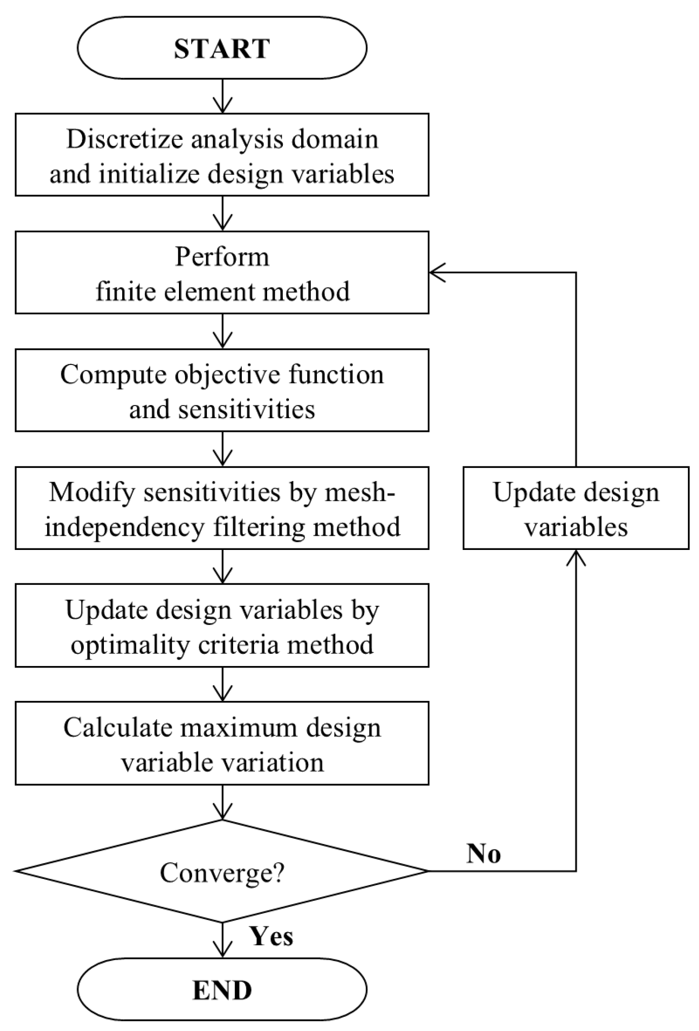
Figure 1. Flowchart of the topology optimization algorithm.
Applsci 15 02829 g001
Figure 2. Electric scooter (Ninebot MAX). (a) Detailed specifications in 2D and 3D diagrams (dimensions shown in millimeters), including loading and boundary conditions. (b) Design area.
Applsci 15 02829 g002
Figure 3. Load and boundary conditions for topology optimization considering multiple loads. Red and blue arrows indicate the applied forces at F 1 (upper point) and F 2 (lower point), respectively.
Applsci 15 02829 g003
Figure 4. Two commercial models for comparison of topology optimization considering the multiple-load conditions.
Applsci 15 02829 g004
Figure 5. Topology optimization results of the electric scooter headtube according to the load conditions. The arrows indicate the direction of the applied loads; the horizontal arrows represent the forces in the x-direction, and the vertical arrows denote the forces in the y-direction.
Applsci 15 02829 g005
Figure 6. Strain energy distribution of electric scooter headtube according to load condition. The arrows indicate the direction of applied loads: horizontal arrows represent forces in the x-direction, while vertical arrows denote forces in the y-direction.
Applsci 15 02829 g006
Figure 7. Average and standard deviation of strain energy from topology optimization results for each group.
Applsci 15 02829 g007
Figure 8. Topology optimization considering multiple loads (Case A) and two commercial models for comparison (Case B and Case C).
Applsci 15 02829 g008
Figure 9. Collision performance of topology optimization design considering multiple loads (Case A) and two models (Case B and Case C) for comparison.
Applsci 15 02829 g009
Figure 10. Comparison of the average values of strain energy for each model (Cases A, B, and C) under different loading conditions.
Applsci 15 02829 g010
Table 1. Topology optimization results for each group.
GroupGroup AGroup BGroup CGroup D
Compliance [ N · m m ]
164.39108231.9428936.7663296.38500
Strain   Energy   [ N · m m ] Max.3.778935.224810.719362.16243
Avg.0.013290.018750.002970.00779
Std.0.046560.064740.010600.02661
Iteration56431248123
Table 2. Collision performance of the topology optimization (A) and two target models (B and C).
Loading Condition (LC)Model
(Case)
Compliance
[ N · m m ]
Strain   Energy   [ N · m m ]
Max.Avg.Std.
LC 1A167.5879 3.96340.01350.0485
B484.8086 3.9177 0.0392 0.1696
C891.5683 14.6701 0.0721 0.3375
LC 2A241.9688 5.3093 0.01960.0673
B427.5641 3.6456 0.0346 0.1374
C858.5088 20.5374 0.0694 0.3546
LC 3A63.81700.62260.00520.0155
B282.5795 2.83430.02800.1154
C447.6028 8.5388 0.03620.1990
LC 4A138.1978 1.9685 0.0112 0.0367
B225.33501.7904 0.0182 0.0752
C414.54327.4465 0.0335 0.1596
Multiple LoadsA105.0518 2.3131 0.0085 0.0290
B298.7380 2.23400.02410.1022
C549.4200 9.1967 0.0444 0.2050
Disclaimer/Publisher’s Note: The statements, opinions and data contained in all publications are solely those of the individual author(s) and contributor(s) and not of MDPI and/or the editor(s). MDPI and/or the editor(s) disclaim responsibility for any injury to people or property resulting from any ideas, methods, instructions or products referred to in the content.