Article

Transcritical R744 Supermarket Refrigeration System Integrated with a Heat-Driven Ejector Chiller

by
Ayan Sengupta
1,
Paride Gullo
2,*,
Vahid Khorshidi
3 and
Mani Sankar Dasgupta
1
1
Smart Building Lab, Department of Mechanical Engineering, BITS, Pilani 333031, Rajasthan, India
2
Institute of Mechanical and Electrical Engineering, University of Southern Denmark (SDU), Alsion 2, 6400 Sønderborg, Denmark
3
Danfoss A/S, Nordborgvej 81, 6430 Nordborg, Denmark
*
Author to whom correspondence should be addressed.
Appl. Sci. 2025, 15(6), 2955; https://doi.org/10.3390/app15062955
Submission received: 15 January 2025 / Revised: 27 February 2025 / Accepted: 5 March 2025 / Published: 10 March 2025
(This article belongs to the Section Energy Science and Technology)

Abstract

:
The subcooling potential of a novel R717-based waste heat-driven multi-ejector chiller (HEC) integrated with an R744 refrigeration system was evaluated for use in supermarkets. The performance was compared with an R744 refrigeration system coupled to R718- and R600a-based HECs, an R744 system equipped with parallel compression (PC), and a standard R744 booster system (CB) in various warm and hot climatic locations. Integration of the R717-based HEC was found to improve the coefficient of performance by 3.7% at 27 °C to 12.1% at 45 °C compared to the R718, and by 1.6% at 27 °C to 7.6% at 45 °C compared to the R600a-based system. The energy-saving potential of the R717 system (6.2% to 9.4%) was also found to be higher than that of the R718 (0.7% to 2.8%) and R600a systems (2.5% to 6.6%). The use of the existing high-pressure controllers of the CB system was found to impose a relatively lower penalty on the system performance compared to the controllers of the PC system. Although the integration of the R718 system incurred a significantly lower additional investment, the recovery time of the R600a-based HEC (2.3–4.8 years) was found to be the shortest.

1. Introduction

Supermarkets are a highly energy-intensive industry, requiring about ~3.5% of the total national electricity in some industrialized nations [1], mainly due to their refrigeration systems [2]. These systems make supermarkets a significant contributor to the indirect emissions of greenhouse gases. In addition, the majority of the commercial refrigeration systems around the globe still operate on high-global warming potential (GWP) synthetic refrigerants, like R404A and R22 [3]. Leakage of these refrigerants thus makes supermarkets a significant contributor to the direct emission of greenhouse gases as well. Meanwhile, enactment of several legislative acts (e.g., reference [4]) have enforced stricter regulations on the use of these high-GWP refrigerants, and they are stipulated to be phased out within a given timeframe. This has encouraged the scientific community to look for suitable alternatives to these high-GWP refrigerants. Several low-GWP refrigerants, including hydro-fluoro-olefins (HFOs) [5], are under consideration. However, HFO usage has given rise to different types of challenges, such as the proliferation of persistent, bio-accumulative, and toxic (PBT) chemicals with potential contamination of soil and water. Therefore, there is substantial investment risk, as in the near future these chemicals could come under restricted usage. Natural refrigerants like R744 appear to be a more dependable solution and a long-term alternative. However, technology development around natural refrigerants has yet to mature. One of the most promising natural refrigerants, R744, suffers from the fact that the efficiency of the refrigeration system rapidly declines with a rise in ambient temperature due to transcritical operation. To overcome such challenges, several technological innovations have been proposed in recent times, such as parallel compression [6], evaporative cooling [7], various subcooling techniques [8,9], waste heat recovery using an organic Rankine cycle [10], use of ejectors [11,12,13], pressure exchangers [14], etc.
There is an enormous amount of waste heat available in supermarkets due to the transcritical operation of R744 systems, which is generally used to meet the district and space heating demands in cold weather locations. However, for supermarkets operating in warm and hot climates, the heating demand is either modest or absent. This necessitates the rejection of the excessive amount of heat to the outdoor air, which is simply wasted. Instead, this heat could be utilized in various ways to improve the efficiency of R744 refrigeration systems. These include powering an organic Rankine cycle to generate electricity, which in turn can be used to partially meet the electricity demand of the refrigeration unit itself [10]. The waste heat can also be utilized for powering either an absorption cycle [15] or a heat-driven ejector chiller [16,17]. These waste heat-driven cycles can be deployed in supermarkets for subcooling the R744 at the gas-cooler outlet. Although substantial research is already available on the integration of absorption cycles with R744 systems [15,18,19], the literature lacks extensive studies on the usage of heat-driven ejector chillers (HEC). Kumar et al. [20] reported an investigation on a heat-driven ejector cycle integrated with a single-stage R744 refrigeration unit. Several refrigerants were evaluated, among which R32 was identified to be the most suitable for the heat-driven cycle. The integrated system was reported to improve the cooling capacity by 10% to 50% over a single-stage refrigeration unit. However, the utilization of the heat-driven ejector unit for subcooling the R744 cycle was not explored in that study. Yadav and Sarkar [21] reported an investigation on an R1234ze(E)-based heat-driven ejector cycle coupled to a single-stage R744 refrigeration system. The integration of an internal heat exchanger in the R744 system with an economizer in the heat-driven system was reported to provide the maximum coefficient of performance (COP). However, adoption of the heat-driven ejector system was reported to increase the installation cost by 1.5 times over the standard R744 system. Ierin et al. [22] reported R1233zd(E) to be a more suitable working fluid compared to R245ca and R601b for the heat-driven ejector cycle. The integration of the heat-driven cycle was reported to improve the COP of the system by 32.7% over a standard single-stage R744 refrigeration system. A major issue with the configuration reported in [22] was the integration of a generator at the outlet of the low-stage compressor to extract heat. This is expected to limit the operating temperature of the generator, which would affect the system performance due to the low discharge temperature of R744. However, due to the limited operating conditions explored in [20,21,22], it was difficult to evaluate the suitability of the heat-driven units in locations experiencing higher ambient temperatures.
Further, none of the above literature was dedicated to the usability of natural refrigerants for the HEC unit. Usage of synthetic refrigerants, including HFOs, is not desirable due to their adverse impact on the environment. Also, none of the studies were dedicated to R744 supermarket refrigeration systems, nor were ejector control strategies or field measurements involved. Apart from this, the concept of a multi-ejector in the HEC unit was not explored in these studies. Recently, an investigation of a heat-driven ejector cycle coupled to an R744 refrigeration system was reported by Sengupta et al. [16] for use in supermarkets. Several environmentally friendly refrigerants were assessed, among which R717 was identified as the best working fluid for the HEC. The combined usage of a multi-ejector rack in the heat-driven cycle and parallel compression in the R744 system was reported to enhance the COP from 4.2% to 23.9% and reduce the annual energy consumption from 2.1% to 9.5% over a standard R744 system in the investigated locations. However, it was reported that the adoption of this new technology would be difficult due to the complexity of its control strategy and intricate circuitry. In particular, developing new controllers for this new technology would be difficult for any manufacturer, as it would require large investments. Further, the use of R717 in a sector like supermarkets could be challenging due to local regulatory measures. Hence, the present work aims to evaluate the potential of this novel subcooling technology in addressing these challenges, focusing on its accessibility and affordability from a practical perspective.
The present study focused on evaluating the potential of a novel R744 refrigeration system equipped with an R717-based heat-driven multi-ejector chiller (HEC) for possible use in supermarkets. The multi-ejector rack of the R717-based HEC consisted of five fixed-geometry ejectors [16]. The performance of the novel configuration was compared with several baselines in terms of COP and energy savings at various warm and hot climatic locations, including India (Chennai and Delhi), the Middle East (Riyadh), the U.S.A. (Phoenix, Tucson, and Las Vegas), and Thailand (Bangkok). Natural refrigerants like R718 and R600a were explored as potential alternatives to R717 for use in the HEC unit. The key performance parameters and the challenges associated with their usage were also addressed to gain better insight. The multi-ejector racks of the R718- and R600a-based HEC were equipped with six to eight fixed-geometry ejectors. Adoption of new technology is always challenging due to the complex nature of its circuitry, which gives rise to the need to develop a new set of controllers, which may increase the investment cost. To counteract this challenge, the performance of the proposed system was also assessed at the optimal operating conditions of a conventional R744 booster system (CB) and a parallel compression-based R744 system (PC). The impact of the shift from the optimal operating conditions on the waste heat recovery potential of the HEC unit and the overall system performance was evaluated to determine the suitability of the existing high-pressure controllers. The economic aspect of the novel subcooling technology was also evaluated in terms of the additional investment incurred due to the integration of R717-, R718-, and R600a-based HECs with the existing R744 refrigeration unit. It is important to note that the supermarket system with a CO2 ejector was not included in the present study due to the following reasons:
  • Inclusion of subcooling is expected to degrade the performance of the CO2 ejector. As subcooling lowers the temperature of the motive stream, it leads to a reduction in the pressure lift, entrainment ratio, and the efficiency of the ejector. This would lead to ineffective utilization of the CO2 ejectors.
  • Inclusion of the CO2 ejector and the associated control systems would further increase the total investment cost.

2. Materials and Methods

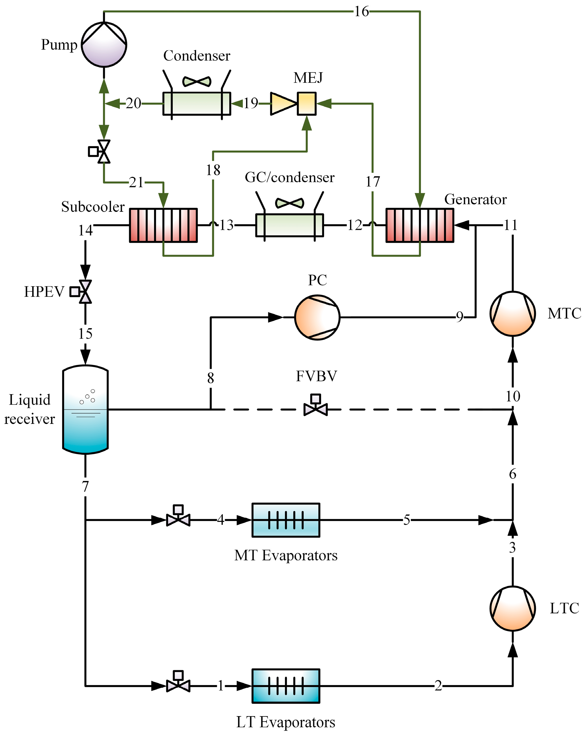
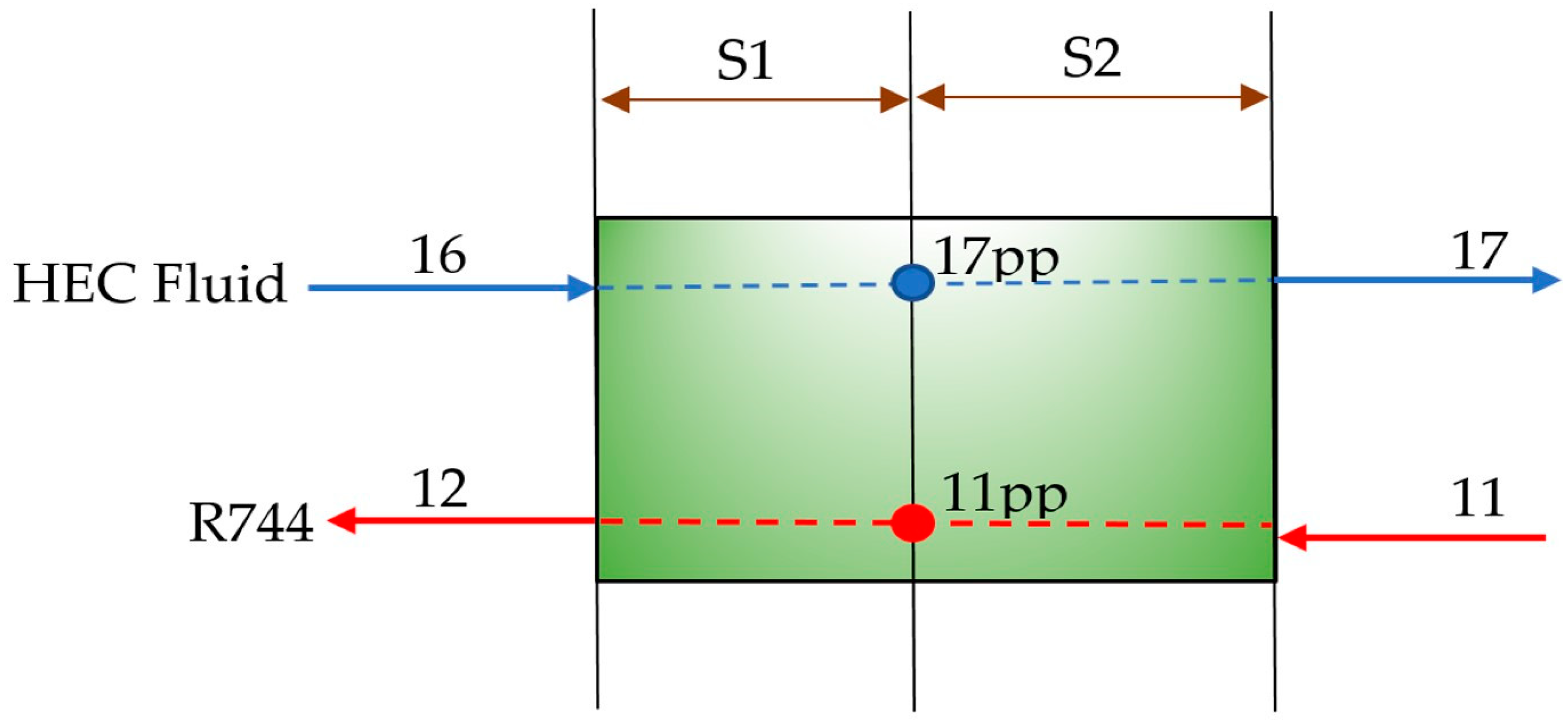
2.1. System Description

The layout of the proposed R744 supermarket refrigeration system coupled to a heat-driven multi-ejector chiller is depicted in Figure 1 [16]. The R744 system includes low-temperature (LT) evaporators and medium-temperature (MT) evaporators for use in LT and MT display cabinets. The low-stage compressors (LTC) are used to pressurize the refrigerant from the outlet of the LT evaporators up to the MT level. The superheat at the outlets of the LT and MT is maintained by the expansion valves upstream of the LT and MT evaporators, respectively. The combined flow from the outlet of the LTC and MT evaporators is pressurized by the medium-stage compressor (MTC) up to the gas-cooler/condenser (GC) pressure. The flash vapor accumulated in the receiver tank is handled by the parallel compressor (PC), which pressurizes the vapor up to the GC pressure. However, below 13 °C outdoor air temperature, the PC was assumed to be switched off [16,23], as the amount of flash vapor in the receiver is generally low. In that case, the vapor is bypassed down to the MT level using the flash vapor bypass valve (FVBV), which also regulates the receiver pressure. Instead of rejecting the entire heat into the ambient air in the GC, a part of this heat could be utilized to drive a heat-driven ejector chiller system (HEC) for subcooling the R744 at the GC outlet. The HEC unit comprises an evaporator/subcooler, a condenser, a generator, a multi-ejector rack (MEJ), a pump, and an expansion valve. A heat source is required for the generator. When integrated with the R744 refrigeration system, this external heat was supplied by the combined high-temperature R744 stream from the discharge of the medium-temperature (MT) and parallel compressors. The heated fluid at the outlet of the generator was fed to the multi-ejector rack (MEJ) as the motive stream. The MEJ rack consists of five fixed-geometry ejectors having different sizes [16]. The detailed specifications of the ejectors used in the HEC cycle are reported in [16]. The high-temperature, high-pressure vapor from the generator enters the motive nozzle of the ejector. The expansion of the motive flow in the nozzle creates low pressure at the nozzle outlet. This causes entrainment of the low-pressure vapor from the evaporator of the HEC (i.e., subcooler of R744 system). The MEJ lifts the refrigerant from the subcooler pressure up to the heat rejection pressure of the condenser. The refrigerant vapor, while passing through the condenser, rejects the heat into the ambient air. A part of the liquid refrigerant from the condenser outlet is pumped back to the generator. The remaining HEC fluid is throttled down to the pressure of the subcooler, in order to extract the heat from the R744 coming from the GC. This causes the temperature of the R744 at the GC outlet to further reduce below the ambient temperature. The subcooled R744 is then expanded down to the receiver pressure through the high-pressure expansion valve (HPEV). The HPEV is also used to regulate the GC pressure.

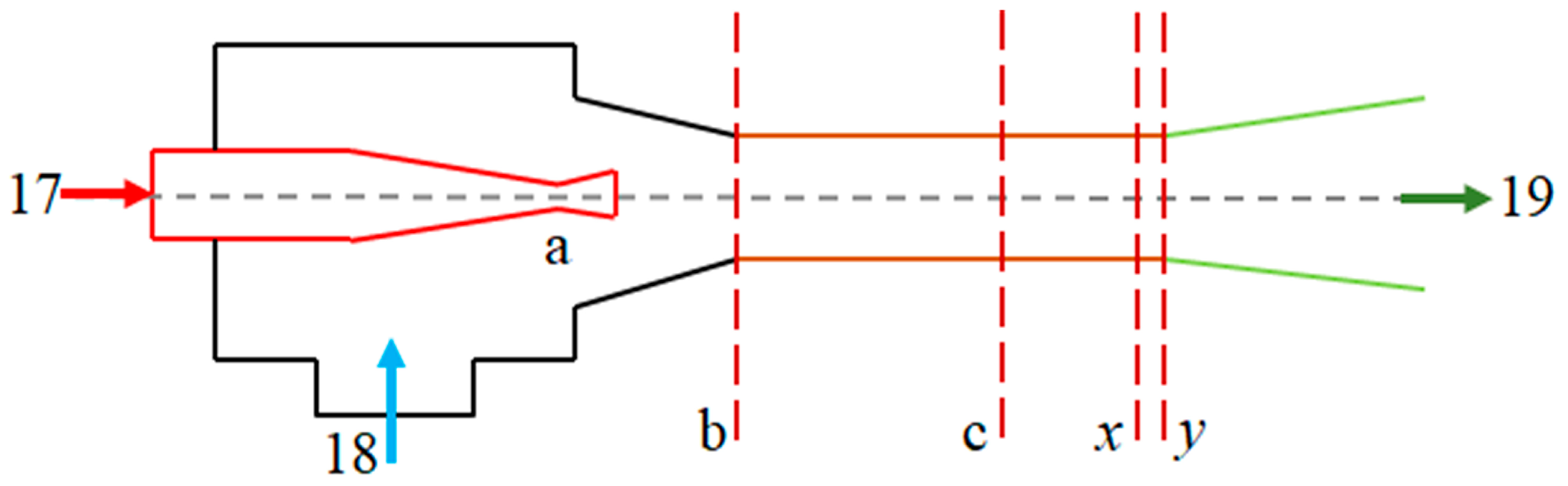
2.2. Mathematical Modeling and Simulation

The set of equations used to model the proposed system are presented in Equations (1)–(15). The following assumptions were taken into consideration in the present study [16]:
  • Steady state operations;
  • Drop in pressure in the heat exchangers and the pipelines were neglected;
  • Constant pressure in the mixing chamber of the ejector;
  • Heat losses/gains from the components were neglected;
  • Kinetic energy of the fluid stream at the inlet of the nozzle and outlet of the diffuser of the ejector were neglected.
The refrigeration load in the MT evaporators was estimated using Equation (1) [11] based on the data obtained from the field measurements reported in [23]. The load had a linear variation from 100 kW to 190 kW with the rise in the outdoor air temperature from 10 °C to 35 °C, respectively. However, the refrigeration load was considered to be fixed at 100 kW at temperatures below 10 °C [23]. The LT refrigeration load ( Q ˙ L T ) was considered to be fixed at 35 kW [16].
Q ˙ M T = 3.6 T a m b + 64
where, T a m b was the outdoor air temperature. The refrigerant flow rates through the LT and MT evaporators were calculated using Equation (2) and Equation (3), respectively.
m ˙ 1 = Q ˙ L T h 2 h 1 = Q ˙ L T h 2 h 7
m ˙ 2 = Q ˙ M T h 5 h 4 = Q ˙ M T h 5 h 7
The refrigerant flow rate handled by the parallel compressor (PC) was calculated using Equation (4).
m ˙ 4 = m ˙ 6 ( 1 x 15 ) m ˙ 6
where, m ˙ 6 m ˙ 6 = m ˙ 1 + m ˙ 2 was the refrigerant flow rate through the MTC compressor, and x 15 was the vapor fraction of the two-phase R744 after expansion in the HPEV (Figure 1). The global efficiencies of the R744 compressors were calculated based on the correlations [24] summarized in Table 1. P s u c , and P d i s were the suction and discharge pressures across the R744 compressors.
The simplified layout of the generator is shown in Figure 2. The generator section of the HEC unit was divided into two sections, S1 and S2, in order to calculate the specific enthalpy of the refrigerants at the section ’11pp’ and ’17pp’. In the generator, the pinch-point temperature (pp) was considered to be 3 K [25].
At state 11pp, the specific enthalpy of R744 was estimated by energy balance in the S2 section of the generator (Equation (5)).
h 11 p p = h 11 m ˙ 8 ( h 17 h 17 p p ) m ˙ 5
At state 17pp, the phase of the HEC fluid was considered as saturated liquid, while at the state 17, the phase was considered as saturated vapor. m ˙ 8 in Equation (5) was the mass flow rate of the working fluid in the HEC cycle through the generator, while m ˙ 5 was the mass flow rate of R744 through the generator. At state 12, the specific enthalpy of R744 was estimated by energy balance in the S1 section of the generator (Equation (6)).
h 12 = h 11 p p m ˙ 8 ( h 17 p p h 16 ) m ˙ 5
The heat removed in the subcooler by the HEC fluid (Equation (7)) was determined iteratively by adjusting a set of variables, which included the GC pressure, degree of subcooling, and the generator temperature [16]. These variables were adjusted in such a way that the heat extracted by the HEC fluid exactly matched the heat rejected by the R744 in the subcooler (Equation (8)) [16]. The pinch-point temperature in the subcooler was assumed to be 3 K [25].
Q ˙ R 744 s u b = m ˙ 5 h 13 T a m b + a p p , P G C h 14 T 13 D O S , P G C
Q ˙ H E C s u b = m ˙ 7 h 18 h 21 = h 20
where, m ˙ 7 was the flow rate of the HEC fluid in the subcooler, app was the approach temperature at the gas-cooler (GC) outlet, DOS was the subcooling degree, and P G C was the pressure in the gas-cooler. The phase of the HEC fluid at the state 20 (Figure 1) was considered as saturated liquid.
The schematic of the ejector section in the HEC cycle is shown in Figure 3. A 1D flow approach similar to that reported in [26] was used to model the ejector.
The velocity of the HEC fluid at state b was calculated from Equation (9) [26]. The velocity of the HEC fluid at state 17 was neglected.
u b = 2 η n o z h 17 h b s P m i x , s 17
where, h b s was the specific enthalpy of the HEC fluid expanding via a reversible adiabatic process, and P m i x was the mixing chamber pressure. The actual specific enthalpy of the motive fluid at the nozzle outlet (section b) was determined by taking into consideration the various losses inside the motive nozzle ( η n o z ) using Equation (10) [26].
η n o z = h 17 h b h 17 h b s
The velocity of the HEC fluid at the nozzle outlet was calculated using Equation (11) [16,26]. Since the increase in entropy during the expansion of the suction stream was very small, the process was assumed to be isentropic [26].
u f = 2 η n o z h 18 h f P m i x , s 18
The specific enthalpy of the refrigerant at section x (Figure 3) was determined by taking into account the losses in the mixing chamber ( η m i x ) using Equation (12) [26].
h x = h 17 + ω h 18 1 + ω 1 2 u b + ω u f 1 + ω η m i x 2
The specific enthalpy of the refrigerant stream at the outlet of the diffuser (State 19 (Figure 3)) was estimated using energy balance across the diffuser section (Equation (13)) [26]. The losses in the diffuser section were taken into account in terms of the efficiency of the diffuser ( η d i f f ).
h 19 = h x + h 19 s P 19 , s x h x η d i f f
The entrainment ratio of the ejector defined as the ratio of the suction to the motive flow rate, was computed using Equation (14) [26].
ω = 2 η n o z h 17 h b s 2 h 19 s h x η d i f f η m i x 2 h 19 s h x η d i f f η m i x 2 h 18 h f = m 7 m 8
The algorithm employed for solving the set of equations governing the functioning of the ejector of the HEC system was obtained from [16,26]. The efficiencies of the nozzle, mixing chamber, and the diffuser section of the ejector were taken as 90%, 80%, and 90% respectively [25].
The efficiency of the proposed system was evaluated in terms of COP, which was estimated using Equation (15).
C O P = Q ˙ L T + Q ˙ M T W ˙ L T C + W ˙ M T C + W ˙ P C + W ˙ f a n + W ˙ P u m p
where, the power required by the LT ( W ˙ L T C ), MT ( W ˙ M T C ), and PC ( W ˙ P C ) compressors were estimated using the correlations for the global efficiencies summarized in Table 1. The power needed by the gas-cooler and condenser fans ( W ˙ f a n ) was assumed to account for about 3% of the total heat rejected in the respective heat exchangers [23]. For the HEC cycle, the pump’s power consumption was calculated using the global efficiency (Equation (16)) reported in [27].
η p u m p g = 0.00026 Δ P d s 2 + 0.025 Δ P d s + 0.002
where, Δ P d s was the difference in pressure between the discharge and suction lines of the pump.
The annual energy consumption by the modified R744 systems was calculated using Equation (17).
A E C = i W ˙ i f i
where, W ˙ i was the power consumed by the investigated systems when operating at the i-th outdoor air temperature and f i was the number of times the i-th temperature was experienced (hours) at a specific location. The frequency of occurrence of a specific temperature at the selected locations (Figure 4) was calculated utilizing the weather files from EnergyPlus [28]. In the present investigation, only warm and hot climatic locations were considered due to the operational constraints of the HEC unit, which is discussed later. Additionally, locations with similar temperature distributions (like Chennai and Bangkok) were evaluated due to the difference in electricity tariffs (~17%). The electricity tariff was expected to have a significant impact on the recovery time associated with the additional investment made on the HEC unit.
The recovery time for the additional investment made (AIRT) on the HEC unit was determined using Equation (18).
A I R T = I n c r e a s e   i n   C a p i t a l   c o s t   ( $ ) E n e r g y   s a v i n g s   kWh × E l e c t r i c i t y   t a r i f f   ( $ kWh )
The energy savings in Equation (18) were computed by considering the PC system as the baseline. Electricity tariffs at various locations considered in the present study were extracted from [29]. The specific installation cost of the R717-based HEC was considered as $434/kWcooling [25]. Due to unavailability of the cost associated with the R718- and R600a-based HECs in the literature, specific installation costs were assumed to be the same as that of R717. The maximum outdoor air temperature that is experienced at a given location was considered to be the design condition. For the present study, the running cost of the HEC system was neglected [25].
The LT and MT evaporators were maintained at −32 °C and −8 °C, respectively, according to the field measurements from [23]. The degrees of superheat for the R744 system and HEC system were considered as 10 K and 4 K [23,25], respectively. The approach temperature (app) at the GC was taken as 2 K [24]. Below 13 °C ambient temperature, the pressure of the receiver tank was set to 35 bar by the FVBV, while beyond 13 °C, the receiver pressure was optimized. The condensing temperature for the HEC cycle was considered to be 7 K above the outdoor air temperature [16], while the lowest temperature for the R744 condenser was set to 9 °C [24]. The R717-based HEC unit was operated only when the outdoor air temperature was above 24 °C [16]. When the temperature ranged from 13 °C to 24 °C, the proposed system operated without the HEC but with the parallel compressors; however, when it was below 13 °C, the parallel compressors were turned off and the system was operated as a standard booster system with the FVBV. The proposed system was optimized for maximizing the COP across the entire range of ambient temperatures by iteratively adjusting the gas-cooler pressure, generator temperature, and the degree of subcooling to balance the heat exchange in the subcooler while maintaining a 3 K pinch constraint in the subcooler and the generator. The refrigerant properties were taken from REFPROP [30] and simulation was performed in MATLAB [31].

3. Results and Discussion

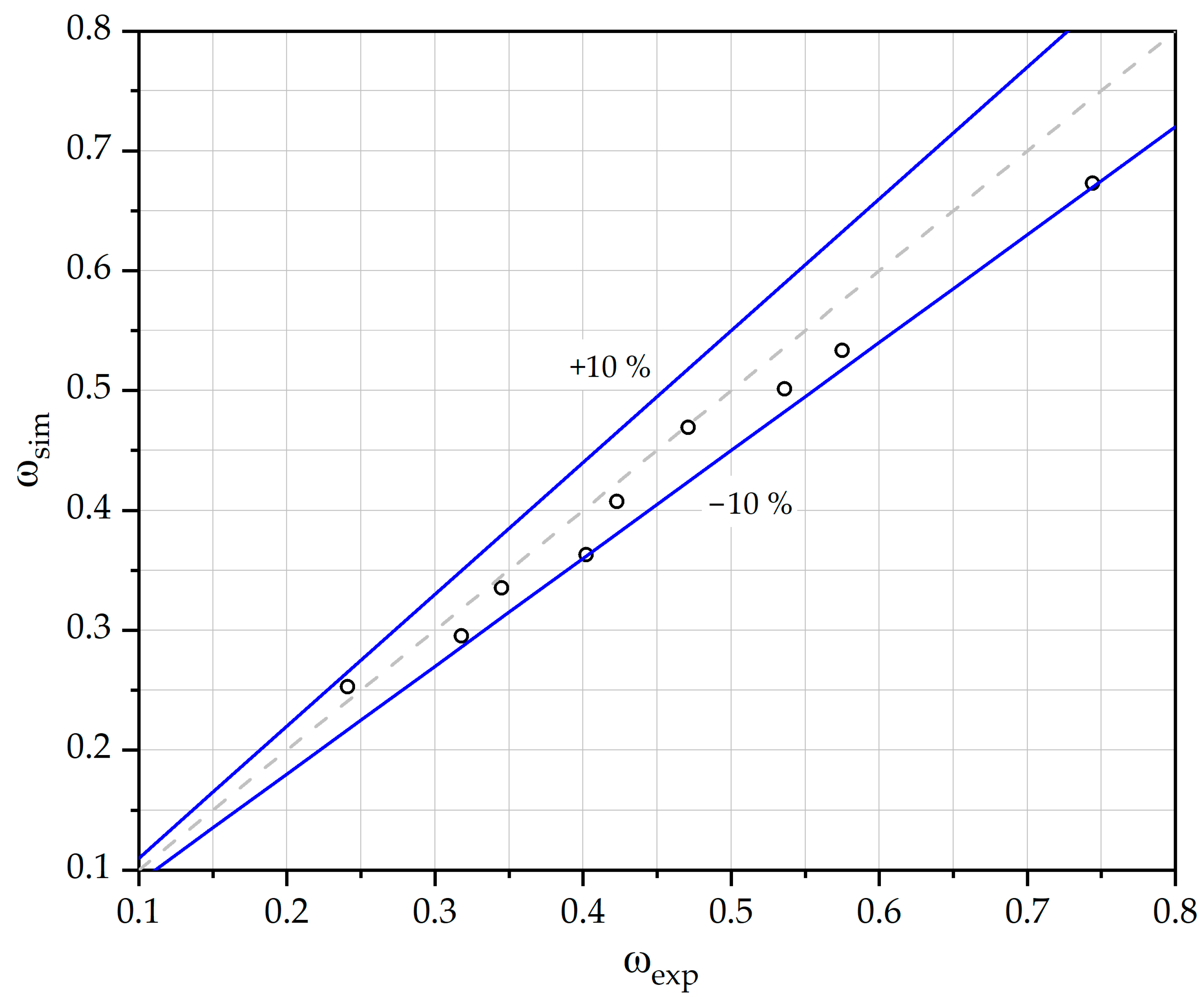
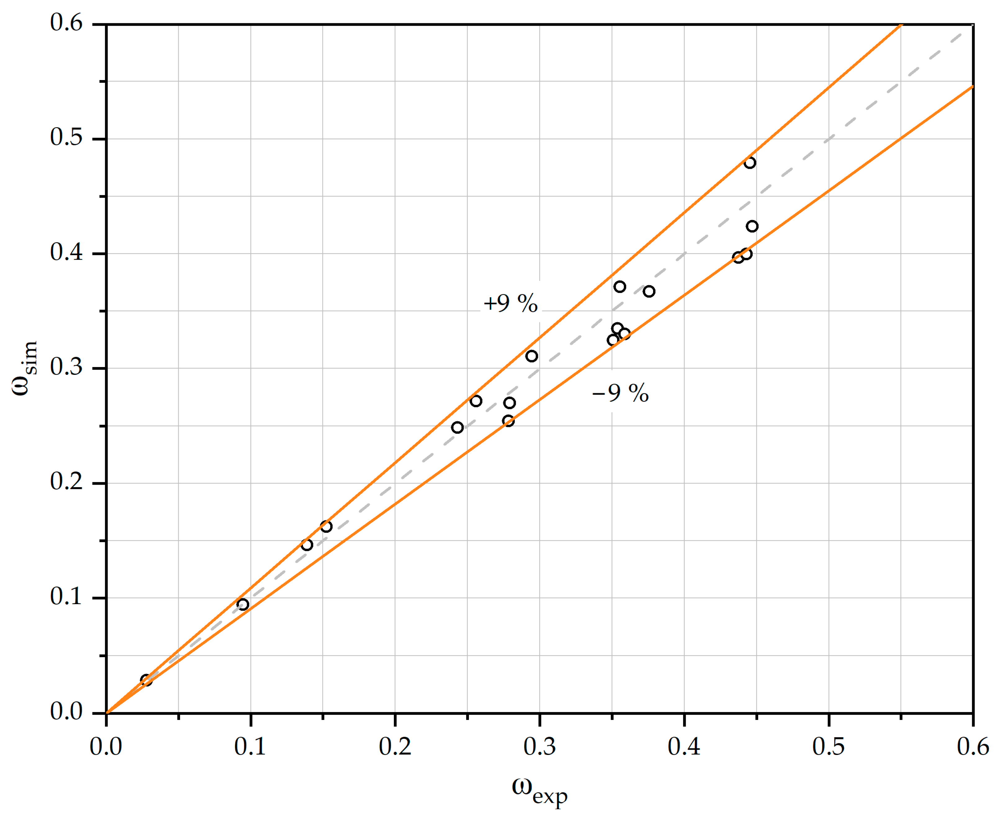
3.1. Experimental Validation of the Ejector Model

The set of equations governing the working of the ejector was validated against published experimental data available for R245fa and R134a as the working fluid [32,33]. The validation was carried out for the generator and condensing temperature ranges of 90 °C to 100 °C and 8 °C to 16 °C for R245fa [32] and 75 °C to 85 °C and 26 °C to 42 °C for R134a [33]. The percentage deviation in terms of discrepancy in the entrainment ratio was found to be within ±10% for R245fa (Figure 5) and ±9% for R134a (Figure 6). The ejector model was also validated with experimental results of an R141b ejector in our previous study [16] and was found to have an accuracy of ±9%. This ascertains the accuracy of the ejector model in capturing the behavior of an actual ejector.

3.2. Experimental Validation of the HEC and the R744 Refrigeration System

The model of the HEC system was validated against available experimental data [34] with R600a as the working fluid in our previous study [16]. The percentage deviation in the COP and entrainment ratio were found to be within ±4.8% and ±0.1%, respectively. The model of the R744 refrigeration system equipped with parallel compression (PC) was also validated in our previous study [16] against published experimental data [7] with percentage deviation within ±10%.

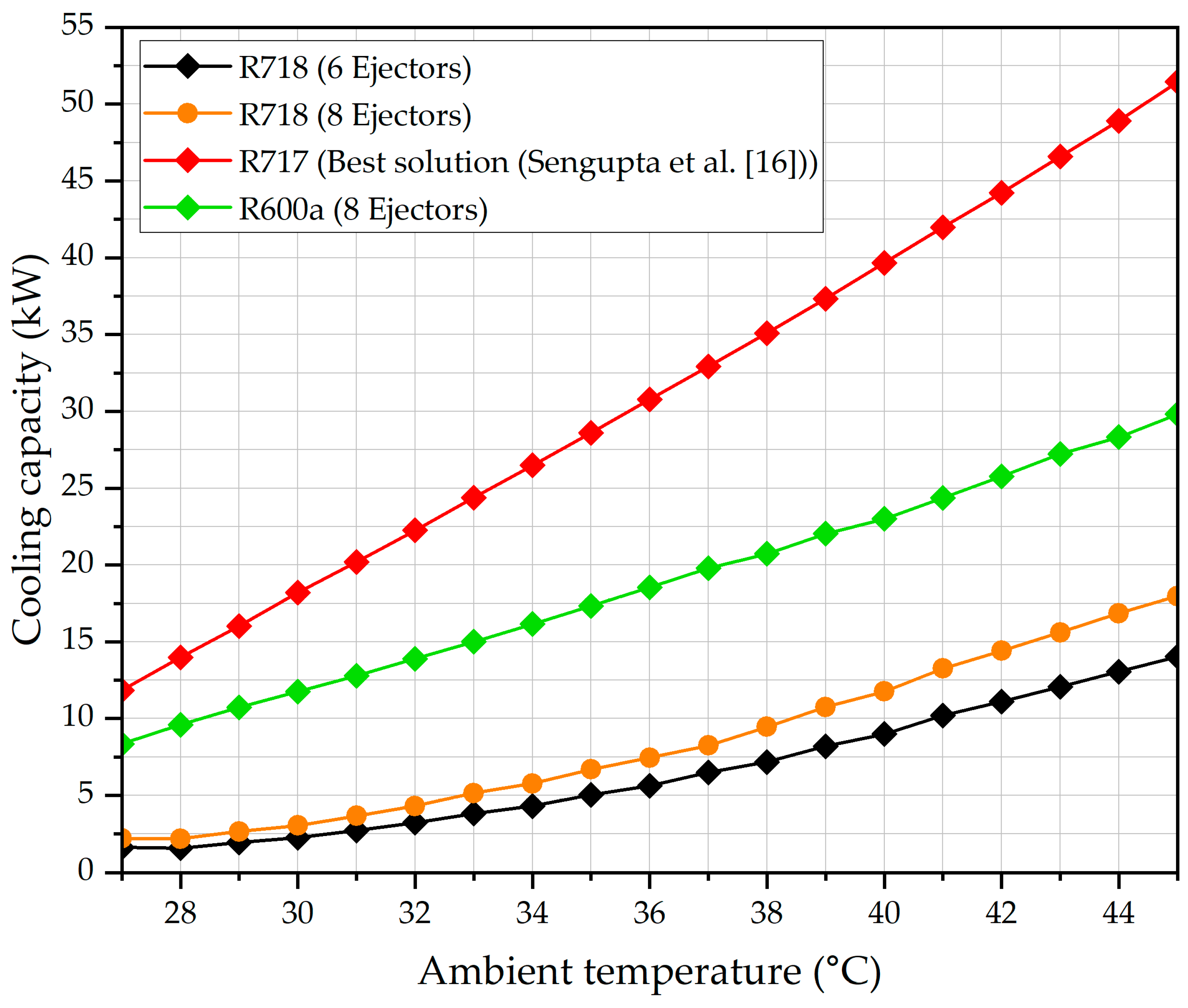
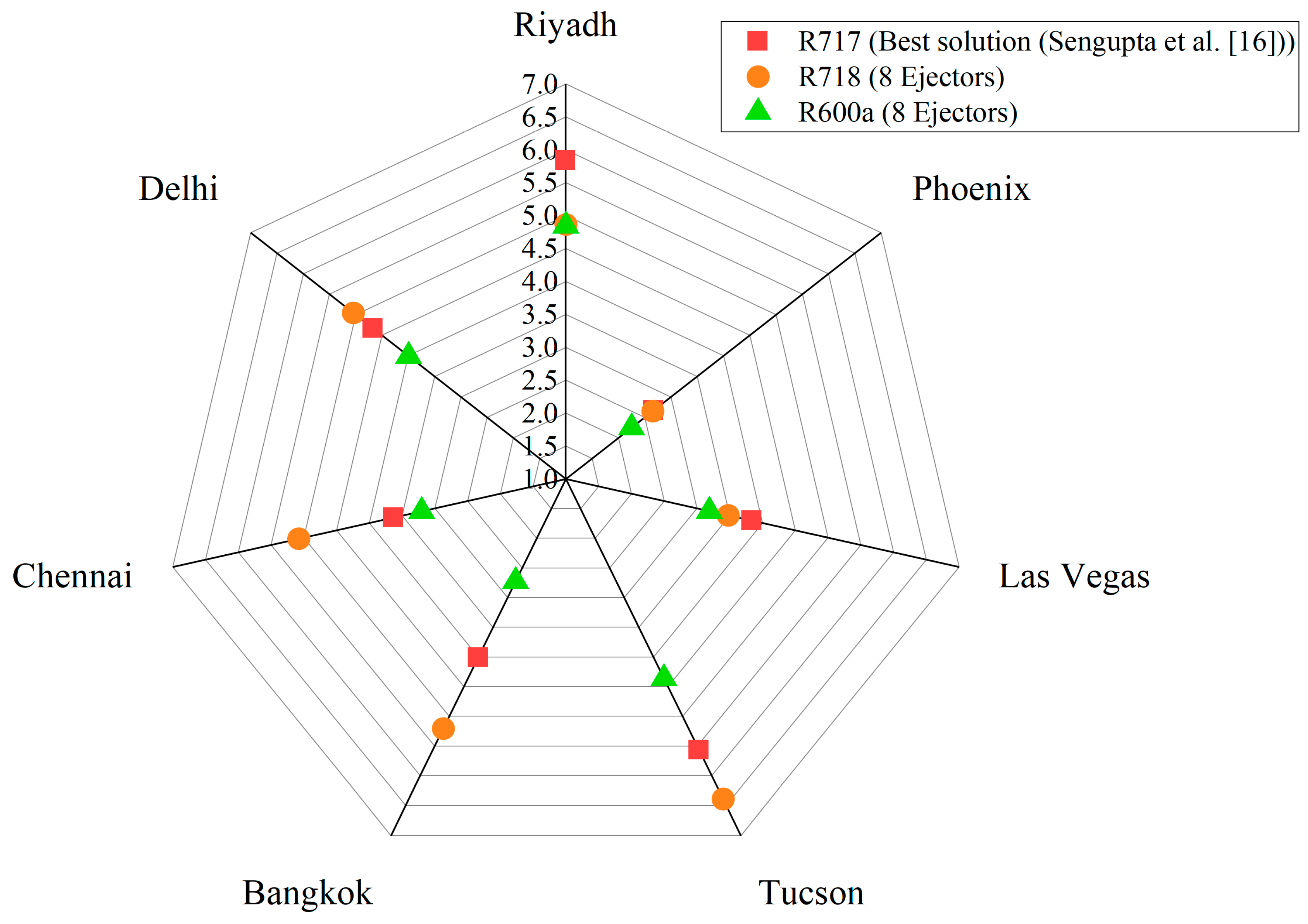
3.3. Performance Comparison of the Proposed System with R717, R718, and R600a as the Refrigerant for the HEC Cycle

The COP of the proposed system was contrasted with several baseline systems. These included an R744 refrigeration system coupled to R718- and R600a-based HECs having six to eight fixed-geometry ejectors in the multi-ejector rack (MEJ). The performance was also compared with an R744 system equipped with parallel compression (PC) and a standard R744 booster system (CB), both without the heat-driven cycle. The results are depicted in Figure 7. Even though the difference in the operating GC pressure was small (Figure 8), the R717-based system having five ejectors was found to outperform the six-ejector-based R718 system by 3.8% at 27 °C to 12.0% at 45 °C ambient temperature, while the same accounted for 3.6% at 27 °C to 10.7% at 45 °C, compared to the eight-ejector-based R718 system. This was due to the fact that the cooling capacity of the R718-based HEC was significantly lower compared to the R717-based system (Figure 9). Switching from six to eight operating ejectors enhanced the capacity of the R718-based HEC from 14 kW to 18 kW at 45 °C ambient temperature, while the same for the R717-based system was around 51 kW. The lower the cooling capacity, the lower the degree of subcooling achieved by the HEC unit. This resulted in the higher accumulation of flash vapor in the liquid receiver of the R744 refrigeration system due to an increase in the quality of the refrigerant entering the receiver. This further increased the power consumed by the parallel compressors, which eventually lowered the system’s efficiency. The lower cooling capacity of the R718-based HEC is attributed to its intrinsic thermo-physical properties. The higher latent heat of vaporization of R718 (Figure 10) signifies that it would require lower mass flow rates compared to R717 for extracting the same amount of heat. However, due to relatively lower vapor density (Figure 11), the volumetric refrigeration capacity is significantly lower than R717. Thus, with the given number of ejectors, the volume of refrigerant flow handled is lower. To accommodate larger volume flow rates, the number of R718 ejectors had to be increased to more than eight. Larger flow rates would lead to higher heat extraction from the R744 in the subcooler. For instance, the use of 14 R718 ejectors reduced the inferiority margin in COP to 5.8% compared to the R717 system; however, the use of more than eight ejectors may not be practically feasible due to escalation in the investment cost. It could also be observed that the R718-based system was able to outperform the PC system only at an outdoor air temperature above 30 °C (Figure 7), while the R717-based HEC was reported to outperform the PC system beyond 24 °C [16]. This significantly reduced the operational range of the R718-based HEC (Figure 12). As a result, the R718-based HEC could be utilized for a relatively smaller fraction of time in a year compared to the R717 system. Below 30 °C, the cooling capacity of the R718-based HEC reduced to less than 2.7 kW at the cost of relatively higher GC pressure compared to the PC system. As a result, the increase in the power required by the parallel compressors was more dominant in governing the system performance compared to the benefits obtained from subcooling at temperatures lower than 30 °C. Thus, the R718-based HEC failed to provide any energy advantage over the PC system below 30 °C and hence was switched off. In that case, the R744 system was operated as the PC system (Figure 12) below 30 °C outdoor air temperature. The R717-based HEC was also found to be superior compared to the eight-ejector-based R600a system by 1.6% at 27 °C to 7.6% at 45 °C ambient temperature. The lower performance of the R600a system was attributed to the fact that its cooling capacity was relatively lower than that of the R717 system (Figure 9). Even with eight ejectors, the cooling capacity of the R600a unit was found to be lower than the R717. This is attributed to its lower volumetric refrigeration capacity compared to R717 (Figure 10 and Figure 11). This indicates that to produce the same cooling effect, the volume flow rate required for R600a is relatively higher than required for R717. With eight ejectors, the volume of refrigerant handled is not sufficient to provide a similar cooling capacity as that of R717. This necessitates the utilization of more than eight ejectors for R600a as well. However, the COP of the R600a-based HEC was found to be higher compared to the R718 system due to relatively higher volumetric refrigeration capacity (Figure 10 and Figure 11). Additionally, the generator temperature of the R718-based HEC was found to be relatively higher than it was in the R600a and R717 systems (Figure 13).

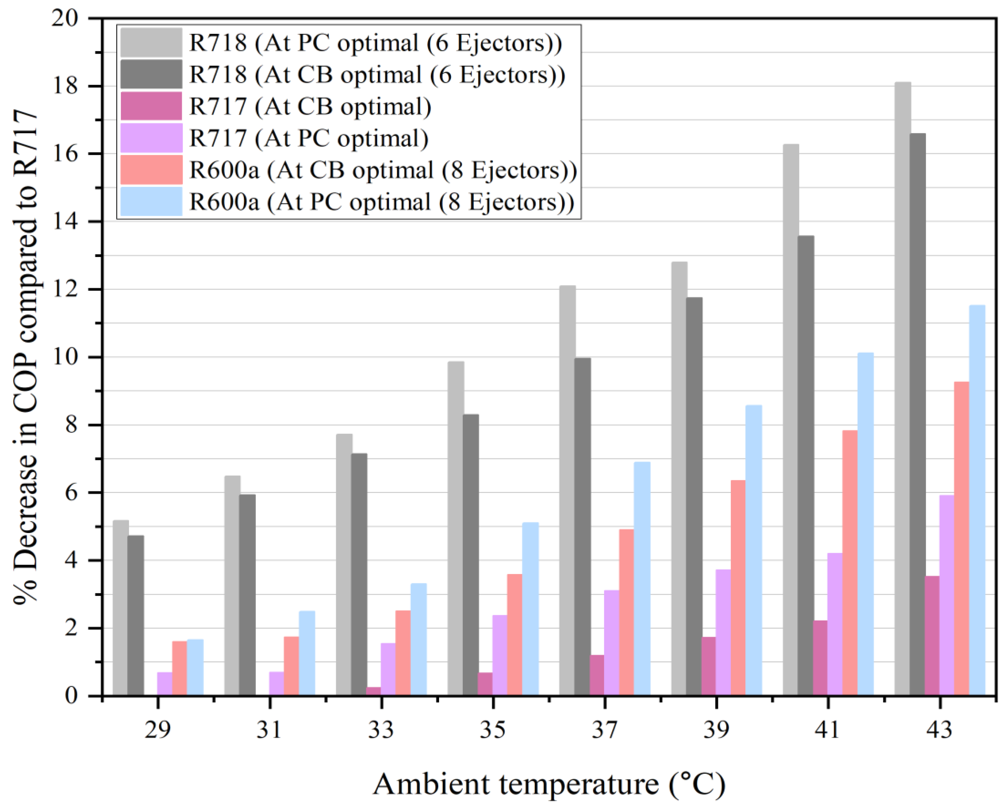
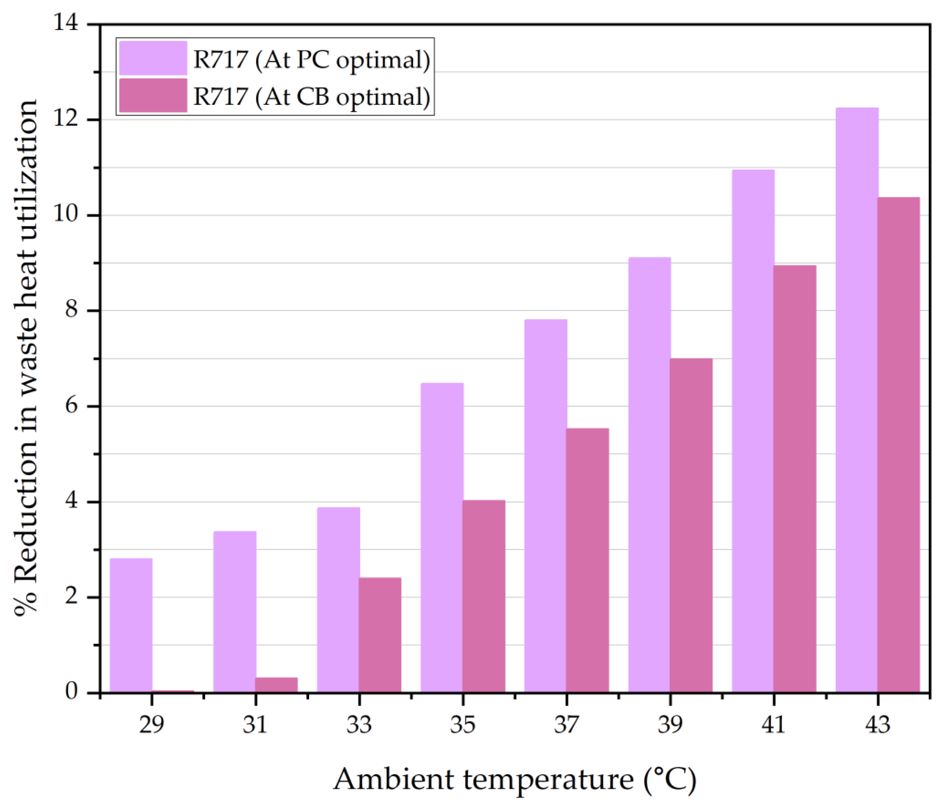
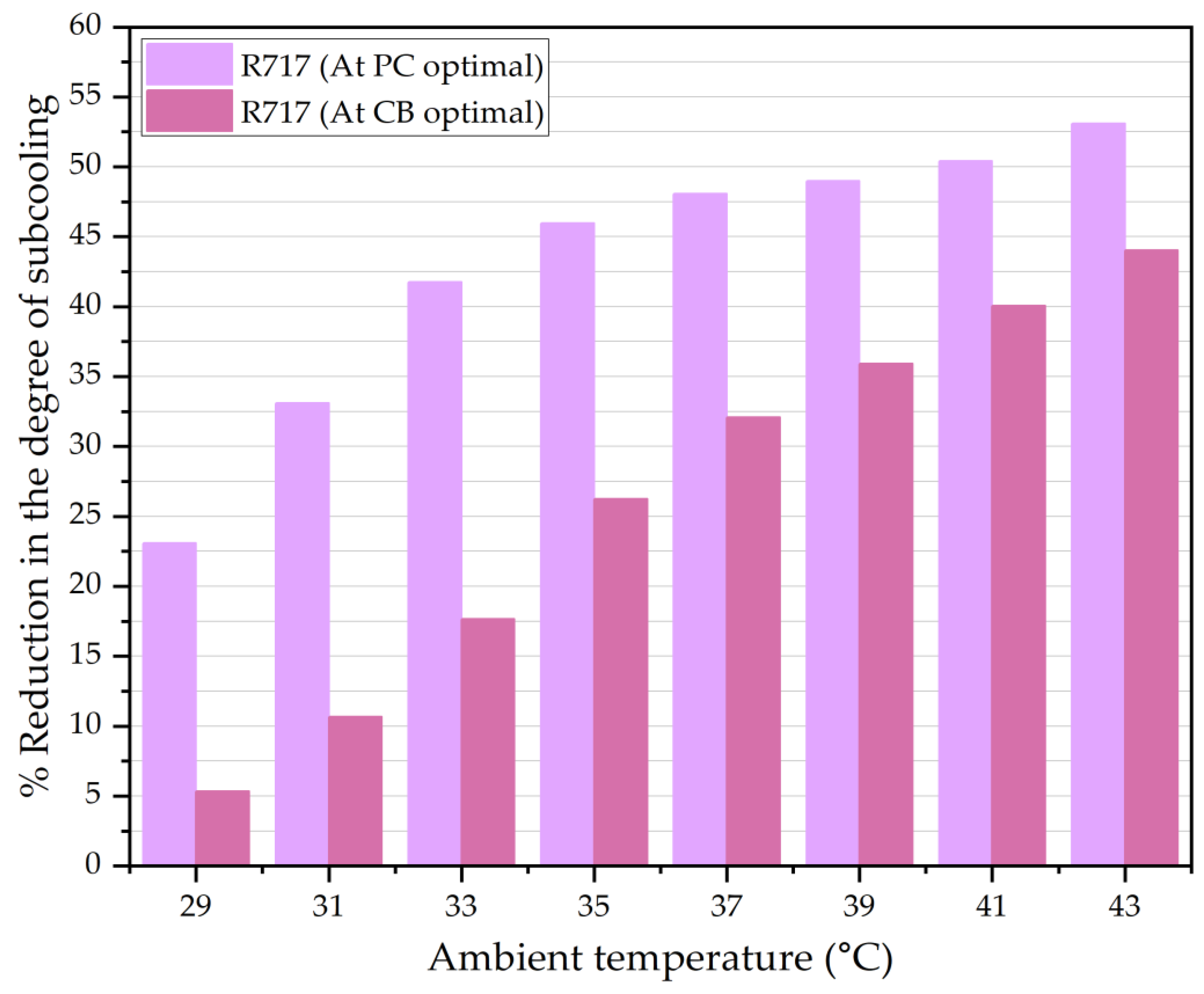
3.4. Impact of Operating the Proposed System at the Optimal Conditions of the Conventional R744 Systems

Adoption of new technology is always challenging due to the complex nature of its circuitry, which gives rise to the need to develop a new set of controllers, which may increase the investment cost. This section evaluates the suitability of the existing high-pressure controllers for use in the proposed system. The R744 refrigeration system integrated with the R717-based HEC was operated at the optimum high-side pressure of the PC system. The results are depicted in Figure 14. Below 32 °C ambient temperature, the penalty on the COP of the proposed system was found to be below 1%. However, as the ambient temperature increased, the deviation was found to rise from 1.5% at 33 °C to 5.9% at 43 °C. This was attributed to the fact that below 32 °C, the difference in the optimal high-side pressure (Figure 15) between the proposed and the PC system was relatively lower (<2.5%), while the same was found to increase by 9.9% at 43 °C ambient temperature. Operating the system at a GC pressure lower than the optimum reduced the quantity of heat extracted from the R744 in the generator (Figure 16), which further reduced the cooling capacity of the HEC and hence the degree of subcooling achieved was relatively lower (Figure 17). As a result, operating the proposed system at the optimal pressure of the PC system resulted in higher flash vapor generation in the liquid receiver, which increased the power consumption significantly. The performance of the proposed system was found to be highly sensitive to the operating GC pressure. At 29 °C ambient temperature, a 2% shift from the optimal pressure reduced the generator heat input by 2.8% and the degree of subcooling by 23%. However, it was interesting to observe that the penalty on the COP was relatively less when the proposed system was operated at the optimum pressure of the CB system (Figure 14). Since the optimum high-side pressure for the CB system was higher compared to that of the PC system (Figure 15), the heat extraction in the generator was relatively higher (Figure 16), which led to higher heat extraction in the subcooler (Figure 17). As a result, the use of the high-pressure controllers of the CB system was found to impose a lower penalty on the system performance compared to the controllers of the PC system. The R744 system integrated with the R718-based HEC also showed a similar trend (Figure 14). However, the penalty with R718 was significantly higher compared to the R717-based HEC. As observed from the previous analysis, the cooling capacity of the R718 system ranged from 2.2 kW to 17.98 kW when operated at its optimal conditions (Figure 9). However, use of the existing high-pressure controllers of the CB and the PC system further reduced its cooling capacity due to operation at relatively lower GC pressure (Figure 8 and Figure 15). Shift from the optimal operating conditions also led to performance depreciation of the R600a-based HEC. However, the penalty imposed with R600a was significantly lower compared to R718.

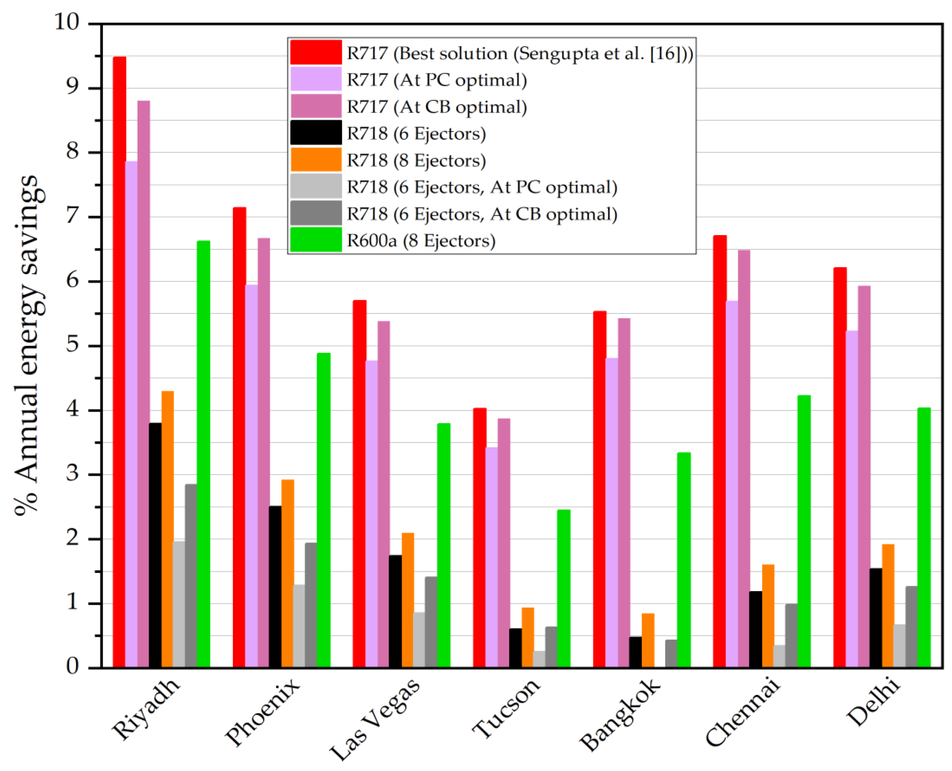
3.5. Energy Savings Comparison Among the Investigated Systems

The energy savings obtained by the investigated systems over the PC system are shown in Figure 18. The energy consumed by the R744 refrigeration system integrated with the R717-based HEC was found to be the lowest at all the selected locations. Among all the locations, the highest energy savings were obtained by the refrigeration unit operating in Riyadh, and the lowest savings were obtained in Tucson. Although the operational time of the R717-based HEC (Figure 11) was the highest in Chennai and Bangkok (i.e., ~96% of the time in a year), the energy savings in these locations were relatively lower than the system operating in Riyadh. This was due to the fact that the ambient temperature went beyond 35 °C for a greater period of time within a year in Riyadh (~20%) compared to Chennai (6.6%) and Bangkok (2%). The improvement margin in COP compared to the PC system was found to increase with the rise in the outdoor air temperature (Figure 7). This signifies that the proposed system was capable of higher energy savings at locations where the ambient temperatures greater than 35 °C were experienced for a significant period of time in a year. The energy-saving potential of the R718-based HEC operating in all the locations was found to be significantly lower compared to the R717-based HEC. This was due to its relatively shorter operating range (Figure 11) compared to the R717-based HEC, which reduced its usage by 22.9% in Riyadh, 24.2% in Phoenix, 18.9% in Las Vegas, 26. 5% in Tucson, 64.2% in Bangkok, 56.0% in Chennai, and 33.0% in Delhi. Switching from six to eight operational R718 ejectors improved the energy savings by 13.3% in Riyadh, 16.8% in Phoenix, 20.6% in Las Vegas, 54.0% in Tucson, 79.0% in Bangkok, 36.0% in Chennai, and 25.0% in Delhi. The R718 systems operating in Bangkok and Tucson were only able to achieve energy savings lower than 1% due to significantly lower operating times (Figure 11). Energy savings obtained by the R600a-based HEC were found to be lower than those of the R717 system at all the selected locations. However, with the same number of operating ejectors, the energy-saving potential of the R600a system was found to be significantly higher compared to the R718 system. It was previously found that the use of existing high-pressure controllers led to depreciation in the system performance due to the shift from optimal operating conditions. This was also reflected in the annual energy savings achieved by the R744 refrigeration unit when operated at the optimal pressure of the PC and the CB systems. The shift from the optimal conditions reduced the energy-saving potential in Riyadh by 17.0% and 7.2% when operated at the optimal pressures of the PC and the CB systems, respectively. A similar trend was observed at other locations. Operating the R718 system at the optimal high-side pressure of the PC and the CB systems in Riyadh reduced its energy-saving potential by 48% and 25%, respectively. Thus, the use of the existing high-pressure controllers of the CB system was found to impose a comparatively lower penalty on the system performance than the controllers of the PC system.

3.6. Economic Analysis of the Investigated Systems

The economic performance of the proposed system was also evaluated in terms of the additional investment incurred upon the integration of the HEC system with the pre-existing R744 refrigeration unit. The savings achieved by the R717-, R718-, and R600a-based systems in terms of energy cost are depicted in Figure 19. Although the proposed system was able to achieve the highest energy savings in Riyadh (Figure 18), the savings in the electricity cost were relatively higher in Chennai. This was due to the higher electricity tariff structure prevailing in Chennai (0.103 $/kWh) compared to Riyadh (0.048 $/kWh). Among all the locations, the cost savings obtained by the proposed system were found to be the highest in Phoenix due to relatively higher tariff (0.166 $/kWh) compared to the other locations. Even though the tariff structure was found to be the highest in the U.S. locations, the savings achieved by the system installed in Tucson and Las Vegas were found to be lower compared to Chennai. This was attributed to the fact that the energy savings achieved in Chennai were comparatively higher than in these U.S. locations (Figure 18). Although the energy savings obtained by the proposed system operating in Delhi were relatively higher, the savings in the electricity cost in Bangkok were higher due to the higher tariff (0.12 $/kWh). As expected, the savings in the electricity cost achieved by the R718- and R600a-based HEC were found to be significantly lower compared to the R717-based HEC unit. However, savings with the R600a-based HEC were found to be higher compared to the R718 unit due to its higher energy-saving potential (Figure 18).
Figure 20 compares the AIRT of the investigated systems at the selected locations. The installation cost of the R717-based HEC unit was found to be significantly higher compared to the R718-based HEC. For instance, the installation of the R717 unit in Riyadh cost around $23,436, while installation of the R718 unit accounted for about $8246. This was attributed to the fact that the capacity of the R717-based HEC unit (55 kW) was relatively higher compared to the R718 unit (~18 kW) at the design condition (Figure 8). The higher the capacity of the HEC unit, the higher its installation cost [25]. It was interesting to observe that the AIRT of the R718 units in Riyadh, Phoenix, and Las Vegas were lower compared to the R717 unit even though its energy saving potential was much lower (Figure 18). However, the recovery time associated with the additional investment made on the R717-based HEC in the remaining locations was found to be relatively lower than that of the R718 unit. The lower installation cost of the R718-based HEC played a key role in lowering the AIRT in Riyadh, Phoenix, and Las Vegas. However, due to significantly lower savings in the electricity cost at the remaining locations (Figure 19), the AIRT associated with the R718 unit was found to be higher than the R717-based HEC. Even though the energy savings obtained by the R717 system were higher compared to the R600a system, the AIRT of the R600a-based HEC was found to be relatively lower in all the selected locations. This was primarily attributed to the lower cost of the R600a-based HEC compared to the R717 unit and significantly higher savings in the electricity cost compared to the R718 unit.

3.7. Selection of the Most Suitable Refrigerant for the HEC Unit and Associated Challenges

From the preceding discussions, R717 was found to be a better solution for the HEC unit compared to R718 and R600a in terms of energy savings. However, R600a provided the lowest AIRT in all the warm and hot climatic locations. Although R717 and R600a are environmentally friendly refrigerants, there are some challenges associated with their usage in supermarkets, where crowd density can be high. The major issue with R717 is its higher level of toxicity (ASHRAE classification = B2L). To counteract this issue, R717 systems can be installed on rooftops to avoid accidents due to leakage. At room temperature, the density of R717 is usually lower than air, which will cause the R717 vapor to rise during leakages. The risk associated with the leakage can be effectively handled if adequate ventilation facilities are available in supermarkets in which the R717-based HEC is installed in the machinery room. Additionally, it is important that the high-pressure relief (safety) valves or overflow valves are integrated with the R717-based HEC to prevent explosion or bursting due to excessive pressure rise in the HEC unit. In case the government regulations restrict the usage of R717 in supermarkets, R600a can be used as a viable alternative. However, R600a is considered to be highly flammable (ASHRAE classification = A3). The R600a-based HEC unit should be isolated from the sales area of the supermarket. Also, measures should be taken to reduce the charge of R600a in the HEC unit by introducing a secondary fluid in between the R744 refrigeration system and the R600a-based HEC unit. This is also applicable for the R717-based HEC unit. It is important to note that the lower flammability limit of R600a is relatively higher compared to other hydrocarbon refrigerants like R290, and its auto-ignition temperature is as high as 460 °C. It is very unlikely that the temperature in the machinery room will reach this limit. If possible, the machinery room should be free of ignition sources. In case these sources cannot be completely isolated, they should be turned off before the lower flammability limit is reached. For this purpose, the machinery room should be equipped with gas detection sensors and proper ventilation and fire extinguishing facilities should be available. R718, being non-toxic as well as non-flammable, can also be adopted as an alternative for the HEC unit. However, the penalty on the system performance with R718 would be significantly higher. R718 is considered to be the ultimate refrigerant; however, at this point, the technological advancements around R718 are not yet matured for its adoption in the HEC circuit. At present, R717 is identified as the best refrigerant for the HEC unit; however, necessary safety measures should be taken for its use in supermarkets.

4. Conclusions

The performance of a novel R744 refrigeration system coupled to a R717-based heat-driven multi-ejector chiller (HEC) was assessed for possible use in supermarkets. The energy-saving potential of the novel system at various warm and hot climatic locations was compared with several baseline systems, including an R744 refrigeration system coupled to R718- and R600a-based HECs, an R744 refrigeration system equipped with parallel compression (PC), and a standard R744 booster system (CB). The performance of the investigated systems was also evaluated at the optimal operating conditions of the PC and CB systems to determine the suitability of the existing high-pressure controllers, as developing a new set of controllers is expected to increase the investment cost. The economic aspect of the investigated systems was also assessed in terms of the additional investment required for the procurement of the HEC unit, providing better insight into this novel subcooling technology. The following conclusions were obtained from the study:
  • The integration of an R717-based HEC was found to improve the COP of the R744 refrigeration system by 3.7% at 27 °C to 12.1% at 45 °C compared to the R718-based HEC, and 1.6% at 27 °C to 7.6% at 45 °C compared to the R600a-based HEC unit;
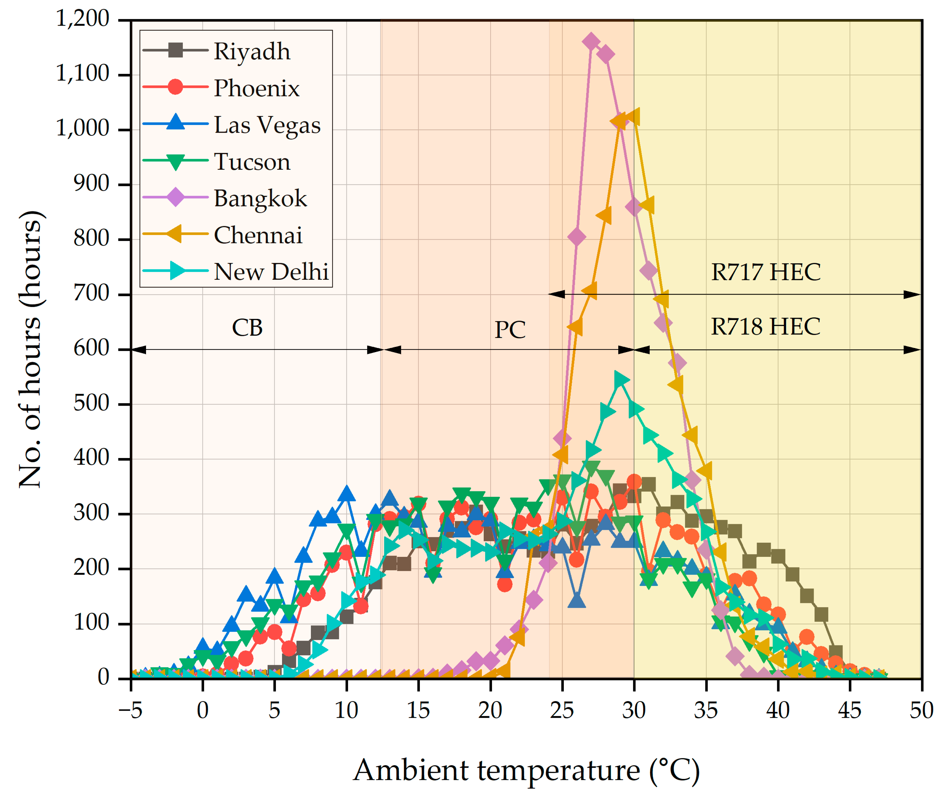
  • The R718-based HEC was found to be effective at outdoor air temperatures above 30 °C, while the R717 system could be operated beyond 24 °C. This tended to reduce the operational range of the R718 system;
  • Even with eight ejectors, the cooling capacities of the R718- and R600a-based HECs were found to be lower by 67% and 42%, respectively, compared to the five-ejector integrated R717 system;
  • The use of CB high pressure controllers with the proposed system was found to impose relatively less penalty in the system performance compared to the high pressure controllers of the PC system;
  • The energy-saving potential of the R744 refrigeration system integrated with the R717-based HEC (6.2% to 9.4%) was found to be relatively higher compared to the R718 (0.7% to 2.8%) and R600a-based HECs (2.5% to 6.6%);
  • Although the additional investment incurred due to the installation of the R718-based HEC was significantly lower compared to the R717 and R600a systems, the AIRT associated with the R600a-based HEC (2.3–4.8 years) was found to be relatively lower than the R717 (2.7–5.8 years) and R718 systems (2.7–6.4 years) in all the selected locations.
  • Even though the initial investment was high, R717 was found to be the best refrigerant for the HEC unit in terms of energy savings; however, necessary safety measures are required to be taken for use in sectors like supermarkets. R718 can definitely be an alternative to R717 in the future, once the technology associated with it becomes matured.

Author Contributions

Conceptualization, A.S., P.G. and V.K.; methodology, A.S. and P.G.; software, A.S.; validation, A.S.; formal analysis, A.S.; investigation, A.S.; writing—original draft preparation, A.S.; writing—review and editing, A.S., P.G., V.K. and M.S.D.; visualization, A.S.; supervision, P.G., V.K. and M.S.D. All authors have read and agreed to the published version of the manuscript.

Funding

This research received no external funding.

Institutional Review Board Statement

Not applicable.

Informed Consent Statement

Not applicable.

Data Availability Statement

The original contributions presented in this study are included in the article. Further inquiries can be directed to the corresponding author.

Conflicts of Interest

Author Vahid Khorshidi was employed by the company Danfoss A/S. The remaining authors declare that the research was conducted in the absence of any commercial or financial relationships that could be construed as a potential conflict of interest.

Nomenclature

appApproach temperature (K)
AECAnnual energy consumption (kWh)
AIRTAdditional investment recovery time (years)
CBConventional booster system
COPCoefficient of performance
DOSDegree of subcooling (K)
fFrequency of ambient temperature (hours)
FVBVFlash vapor by-pass valve
GCGas cooler
GWPGlobal warming potential
hSpecific enthalpy (kJ/kg)
HECHeat driven ejector chiller
HFOHydro-fluoro-olefin
HPEVHigh pressure expansion valve
LTLow temperature
LTCLow temperature compressor
m ˙ Mass flow rate (kg/s)
MEJMulti-ejector rack
MTMedium temperature
MTCMedium temperature compressor
PPressure (kPa)
ppPinch point temperature (K)
PBTPersistent, bio-accumulative, and toxic
PCParallel compressor
Q ˙ Refrigeration load (kW)
sSpecific entropy (kJ/kg-K)
TTemperature (°C)
uVelocity (m/s)
W ˙ Power consumption (kW)
xQuality of refrigerant
Subscripts
ambAmbient
diffDiffuser
disDischarge
expExperimental
mixMixing chamber
nozNozzle
satSaturation
simSimulation
subSub-critical
sucSuction
vapVapor
Greek
ηEfficiency
ωEntrainment ratio
ρ Density (kg/m3)

References

  1. Tassou, S.A.; Ge, Y.; Hadawey, A.; Marriott, D. Energy consumption and conservation in food retailing. Appl. Therm. Eng. 2011, 31, 147–156. [Google Scholar] [CrossRef]
  2. Lundqvist, P. Recent Refrigeration Equipment Trends in Supermarkets: Energy Efficiency as Leading Edge; Academia Press: Cambridge, MA, USA, 2000. [Google Scholar]
  3. Schönenberger, J.; Hafner, A.; Banasiak, K.; Girotto, S. Experience with ejectors implemented in a R744 booster system operating in a supermarket. In Proceedings of the 11th IIR Gustav Lorentzen Conference on Natural Refrigerants, Hangzhou, China, 31 August–2 September 2014. [Google Scholar]
  4. Schulz, M.; Kourkoulas, D. Regulation (EU) No 517/2014 of the European Parliament and of the Council of 16 April 2014 on fluorinated greenhouse gases and repealing Regulation (EC) No. 842/2006. Off. J. Eur. Union 2014, 2014, L150/195-230. [Google Scholar]
  5. What Are HFOs? Available online: https://advancedmaterials.honeywell.com/be/en/hfo-facts/what-are-hfos (accessed on 2 April 2024).
  6. Chesi, A.; Esposito, F.; Ferrara, G.; Ferrari, L. Experimental analysis of R744 parallel compression cycle. Appl. Energy 2014, 135, 274–285. [Google Scholar] [CrossRef]
  7. Lata, M.; Gupta, D.K. Simulation and performance evaluation of trans-critical CO2 refrigeration system with modified evaporative cooled finned tube gas cooler in Indian context. Appl. Therm. Eng. 2021, 186, 116500. [Google Scholar] [CrossRef]
  8. Liu, X.; Yu, K.; Wan, X.; Li, X. Performance evaluation of CO2 supermarket refrigeration system with multi-ejector and dedicated mechanical subcooling. Energy Rep. 2021, 7, 5214–5227. [Google Scholar] [CrossRef]
  9. Casi, Á.; Aranguren, P.; Araiz, M.; Sanchez, D.; Cabello, R.; Astrain, D. Performance assessment of an experimental CO2 transcritical refrigeration plant working with a thermoelectric subcooler in combination with an internal heat exchanger. Energy Convers. Manag. 2022, 268, 115963. [Google Scholar] [CrossRef]
  10. Bellos, E.; Tzivanidis, C. Incorporation of an organic Rankine cycle in a transcritical booster CO2 refrigeration system. Int. J. Energy Res. 2020, 44, 7974–7988. [Google Scholar] [CrossRef]
  11. Pardiñas, Á.; Hafner, A.; Banasiak, K. Integrated R744 ejector supported parallel compression racks for supermarkets. Experimental results. In Proceedings of the 13th IIR Gustav Lorentzen Conference on Natural Refrigerants, Valencia, Spain, 18–20 June 2018. [Google Scholar]
  12. Singh, S.; Hafner, A.; Maiya, M.P.; Banasiak, K.; Neksa, P. Multiejector CO2 cooling system with evaporative gascooler for a supermarket application in tropical regions. Appl. Therm. Eng. 2021, 190, 116766. [Google Scholar] [CrossRef]
  13. Toffoletti, G.; Barta, R.B.; Grajales, S.M.; Liu, H.; Ziviani, D.; Groll, E. Experimental comparison of cycle modifications and ejector control methods using variable geometry and CO2 pump in a multi-evaporator transcritical CO2 refrigeration system. Int. J. Refrig. 2025, 169, 226–240. [Google Scholar] [CrossRef]
  14. Saeed, M.Z.; Hafner, A.; Thatte, A.; Gabrielii, C.H. Simultaneous implementation of rotary pressure exchanger and ejectors for CO2 refrigeration system. In Proceedings of the 15th IIR Gustav Lorentzen Conference on Natural Refrigerants, Trondheim, Norway, 13–15 June 2022. [Google Scholar]
  15. Guruchethan, A.M.; Reddy, Y.S.K.; Maiya, M.P.; Hafner, A. Performance evaluation of absorption cooling assisted transcritical CO2 refrigeration systems. Int. J. Refrig. 2023, 155, 362–374. [Google Scholar] [CrossRef]
  16. Sengupta, A.; Gullo, P.; Khorshidi, V.; Dasgupta, M.S. Waste heat utilization: Energy and economic benefits from multi-ejector chiller sub-cooling R744 supermarket refrigeration systems. Energy 2024, 312, 133657. [Google Scholar] [CrossRef]
  17. Mastrullo, R.; Mauro, A.W.; Napoli, G.; Viscito, L. Thermo-economic optimization and environmental analysis of a waste heat driven multi-ejector chiller for maritime applications. Case Stud. Therm. Eng. 2024, 54, 104081. [Google Scholar] [CrossRef]
  18. Arora, A.; Singh, N.K.; Monga, S.; Kumar, O. Energy and exergy analysis of a combined transcritical CO2 compression refrigeration and single effect H2O-LiBr vapour absorption system. Int. J. Exergy 2011, 9, 453–471. [Google Scholar] [CrossRef]
  19. Bellos, E.; Tzivanidis, C. Enhancing the performance of a CO2 refrigeration system with the use of an absorption chiller. Int. J. Refrig. 2019, 108, 37–52. [Google Scholar] [CrossRef]
  20. Kumar, K.; Gupta, H.K.; Kumar, P. Analysis of a hybrid transcritical CO2 vapor compression and vapor ejector refrigeration system. Appl. Therm. Eng. 2020, 181, 115945. [Google Scholar] [CrossRef]
  21. Yadav, V.K.; Sarkar, J. Thermodynamic, economic, and environmental analyses of various novel ejector refrigeration subcooled transcritical CO2 systems. Int. J. Energy Res. 2021, 45, 16115–16133. [Google Scholar] [CrossRef]
  22. Ierin, V.; Chen, G.; Volovyk, O.; Shestopalov, K. Hybrid two–stage CO2 transcritical mechanical compression–ejector cooling cycle: Thermodynamic analysis and optimization. Int. J. Refrig. 2021, 132, 45–55. [Google Scholar] [CrossRef]
  23. Karampour, M.; Sawalha, S. State-of-the-art integrated CO2 refrigeration system for supermarkets: A comparative analysis. Int. J. Refrig. 2018, 86, 239–257. [Google Scholar] [CrossRef]
  24. Gullo, P.; Elmegaard, B.; Cortella, G. Energy and environmental performance assessment of R744 booster supermarket refrigeration systems operating in warm climates. Int. J. Refrig. 2016, 64, 61–79. [Google Scholar] [CrossRef]
  25. Lillo, G.; Mastrullo, R.; Mauro, A.W.; Trinchieri, R.; Viscito, L. Thermo-economic analysis of a hybrid ejector refrigerating system based on a low grade heat source. Energies 2020, 13, 562. [Google Scholar] [CrossRef]
  26. Chen, J.; Havtun, H.; Palm, B. Investigation of ejectors in refrigeration system: Optimum performance evaluation and ejector area ratios perspectives. Appl. Therm. Eng. 2014, 64, 182–191. [Google Scholar] [CrossRef]
  27. Viscito, L.; Lillo, G.; Napoli, G.; Mauro, A.W. Waste heat driven multi-ejector cooling systems: Optimization of design at partial load; seasonal performance and cost evaluation. Energies 2021, 14, 5663. [Google Scholar] [CrossRef]
  28. EnergyPlus. Available online: https://energyplus.net/weather (accessed on 2 April 2024).
  29. Electricity Prices Around the World. Available online: https://www.globalpetrolprices.com/electricity_prices/ (accessed on 2 April 2024).
  30. Lemmon, E.W.; Bell, I.H.; Huber, M.L.; McLinden, M.O. NIST Standard Reference Database 23: Reference Fluid Thermodynamic and Transport Properties-REFPROP, Version 10.0; National Institute of Standards and Technology, Standard Reference Data Program: Gaithersburg, MD, USA, 2018.
  31. The MathWorks, Inc. MATLAB, Version: 9.13.0 (R2022b). Available online: https://www.mathworks.com (accessed on 2 April 2024).
  32. Shestopalov, K.O.; Huang, B.J.; Petrenko, V.O.; Volovyk, O.S. Investigation of an experimental ejector refrigeration machine operating with refrigerant R245fa at design and off-design working conditions. Part 2. Theoretical and experimental results. Int. J. Refrig. 2015, 55, 212–223. [Google Scholar] [CrossRef]
  33. Li, F.; Li, R.; Li, X.; Tian, Q. Experimental investigation on a R134a ejector refrigeration system under overall modes. Appl. Therm. Eng. 2018, 137, 784–791. [Google Scholar] [CrossRef]
  34. Śmierciew, K.; Gagan, J.; Butrymowicz, D.; Karwacki, J. Experimental investigations of solar driven ejector air-conditioning system. Energy Build. 2014, 80, 260–267. [Google Scholar] [CrossRef]
Figure 1. Schematic of the R744 refrigeration unit equipped with parallel compression and HEC [16].
Applsci 15 02955 g001
Figure 2. Simplified layout of the generator.
Applsci 15 02955 g002
Figure 3. Sectional view of the ejector.
Applsci 15 02955 g003
Figure 4. Bin-hour temperature distribution at the selected locations.
Applsci 15 02955 g004
Figure 5. Experimental validation of the entrainment ratio of an R245fa ejector.
Applsci 15 02955 g005
Figure 6. Experimental validation of the entrainment ratio of an R134a ejector.
Applsci 15 02955 g006
Figure 7. COP comparison among the investigated systems.
Applsci 15 02955 g007
Figure 8. Optimum operating gas-cooler pressures for the R717-, R718-, and R600a-based R744 refrigeration systems.
Applsci 15 02955 g008
Figure 9. Comparison of cooling capacities between R717-, R718-, and R600a-based systems.
Applsci 15 02955 g009
Figure 10. Specific enthalpy of vaporization (kJ/kg) of the refrigerants at various temperatures.
Applsci 15 02955 g010
Figure 11. Vapor density of the refrigerants at various temperatures.
Applsci 15 02955 g011
Figure 12. Operational ranges of the R717- and R718-based HECs.
Applsci 15 02955 g012
Figure 13. Optimum generator temperatures for the R717-, R718-, and R600a-based HECs.
Applsci 15 02955 g013
Figure 14. Performance depreciation due to use of existing optimal high-pressure strategy.
Applsci 15 02955 g014
Figure 15. Comparison of the optimum gas-cooler pressure.
Applsci 15 02955 g015
Figure 16. Impact on the waste heat utilization due to shift from optimum operation.
Applsci 15 02955 g016
Figure 17. Percentage reduction in the subcooling potential due to shift from optimum operation.
Applsci 15 02955 g017
Figure 18. Comparison of the energy savings obtained by the various systems.
Applsci 15 02955 g018
Figure 19. Savings on the electricity cost by the investigated systems.
Applsci 15 02955 g019
Figure 20. AIRT comparison of the R717- and R718-based HEC units at various locations.
Applsci 15 02955 g020
Table 1. Global efficiencies of the R744 compressors.
CompressorOperating ModeGlobal Efficiency [24]
LTCSubcritical η L T C = 0.0012 P d i s P s u c 2 0.0087 P d i s P s u c + 0.6992
MTCSubcritical η M T C s u b = 0.1155 P d i s P s u c 2 + 0.5762 P d i s P s u c 0.0404
MTCTranscritical η P C s u b = 0.172 P d i s P s u c 2 + 0.7095 P d i s P s u c 0.0373
PCSubcritical η M T C t r a n s = 0.0021 P d i s P s u c 2 0.0155 P d i s P s u c + 0.7325
PCTranscritical η P C t r a n s = 0.0788 P d i s P s u c 2 + 0.3708 P d i s P s u c + 0.2729
Disclaimer/Publisher’s Note: The statements, opinions and data contained in all publications are solely those of the individual author(s) and contributor(s) and not of MDPI and/or the editor(s). MDPI and/or the editor(s) disclaim responsibility for any injury to people or property resulting from any ideas, methods, instructions or products referred to in the content.

