Article

Calculation Schemes for Determining Contact Stresses in Railway Rails

by
Valerii Kosarchuk
1,
Volodymyr Tverdomed
2 and
Olha Bambura
1,3,*
1
Department of Mechanical Engineering and Digital Technologies, State University of Infrastructure and Technologies, 9 Kyrylivska Str., 04071 Kyiv, Ukraine
2
Department of Railway Track and Track Management, State University of Infrastructure and Technologies, 9 Kyrylivska Str., 04071 Kyiv, Ukraine
3
Department of Process Control, AGH University of Krakow, 30 Adama Mickiewicza al., 30-059 Krakow, Poland
*
Author to whom correspondence should be addressed.
Appl. Sci. 2025, 15(6), 2970; https://doi.org/10.3390/app15062970
Submission received: 14 February 2025 / Revised: 2 March 2025 / Accepted: 6 March 2025 / Published: 10 March 2025
(This article belongs to the Section Mechanical Engineering)

Abstract

:
One of the tasks of ensuring the safe and sustainable operation of railway transport is to assess the life cycle of the railway track and its elements—in particular, rails. It is known that the main cause of their failure is the development of defects that arise as a result of contact of rails with the wheels of rolling stock—contact fatigue defects. Modern approaches to predicting the contact-fatigue endurance of railway rails and wheels of rolling stock are based on the use of the kinetic theory of damage. The basis of such predictions is the calculation of the stress–strain state of rails under the action of combinations of external force and temperature influences, which is associated with the need to solve spatial boundary value problems of contact interaction. The complexity of such problems necessitates the use of numerical methods, such as the finite element method in particular, for their solution. This paper considers the features of constructing calculation schemes for such problems. Attention is primarily paid to assessing the influence of some design parameters of the rail track and wheels on the magnitude and distribution of stresses in the contact zone. The results will be useful for understanding the physical processes of damage accumulation, the occurrence and development of defects in rails and wheels, as well as for developing methods for predicting the contact fatigue endurance of important elements of railway infrastructure.

1. Introduction

Recently, there have been many publications of the results of research on modeling the life cycle of railway rails [1,2,3]. The relevance of this topic is associated with the need to plan certain types of repair work on the track, since these models make it possible to predict the durability of the track depending on its operating conditions [4]. A railway track is a complex spatial structure consisting of many elements, including rails, sleepers, spacers, fasteners, as well as ballast. All these components of the upper structure of the track differ significantly in shape, dimensions, materials, and mechanical and thermophysical properties. Rails often fail due to direct interaction with the wheels of rolling stock and require repair and replacement and therefore are the most valuable component of the railway track. One of the main causes of rail damage is the formation of specific defects that are of a contact-fatigue nature [5,6,7,8]. The main types of such defects on the rail surface include cracks on the lateral side of the rail head (head checking), surface metal delamination (spalling), localized metal chipping on the running surface (flaking), horizontal delamination of the rail head due to the appearance and growth of internal cracks under the running surface (squats) or propagation of cracks originating from the rail’s lateral edges (shells) [7,9,10]. All these defects are related to the formation of external fatigue cracks (on running surfaces) and internal (at some depth below the running surface) and their subsequent interaction during propagation.
External cracks occur as a result of the exhaustion of the plastic properties of the thin surface layers of the rail material due to the cyclic action of high contact stresses, combined with shear stresses caused by wheel slippage in longitudinal and transverse directions, compressive stresses from rail bending, shear stresses from compressed rail torsion, and residual technological stresses. Thus, microcracks (head checking) on the side face of the rail head in curved sections of the track appear in places with increased material hardness, which is the result of deformation hardening of the surface layers due to the action of high tangential stresses during micro-slipping of the wheels. Areas with increased hardness are very narrow (less than 0.5 mm) and are located periodically at a distance from 2 to 5 mm from each other (Figure 1a). Cracks propagate downward from the lateral edge at an angle of ~45° to the direction of movement and penetrate the metal at an angle of ~15° to the face surface.
At the same time, in the middle part of the rail head, such surface cracks are located chaotically (Figure 1b), which indicates that the wheels slip relative to the rail which occurs in various directions and the entire rolling surface is subjected to work hardening. At the same time, in the central part of the rail head, such surface cracks are distributed chaotically (Figure 1b), indicating that wheel slippage relative to the rail occurs in various directions and the entire running surface is subjected to work hardening. The thickness of the work-hardened layer depends on the properties of the rail and wheel materials, their relative hardness, technological stresses, temperature, etc., and can reach several millimeters.
For internal cracks, the mechanism of formation is different. It is associated with the cyclic action of contact stresses (shear stresses from wheel micro-slippage have a negligible effect on their magnitude), which can cause plastic deformation of the rail material at a certain depth from the running surface (starting from 2 mm and beyond, depending on the axial load). Given the complexity of loading processes (stress trajectories are non-proportional) and their cyclic nature, deformation accumulation (ratcheting) occurs, leading to the exhaustion of the plastic properties of the material and the formation of cracks, which subsequently develop through fatigue mechanisms. The initiation sites of cracks are influenced by material homogeneity, purity, anisotropy of mechanical properties, the distribution of residual technological stresses, and many other factors.
As such, predicting the service life of rails and rolling stock wheels (as they undergo similar defect formation processes) remains a highly challenging engineering problem. These predictions are based on calculating the stress–strain state of rails under combinations of external mechanical and thermal influences.
Recently, there has been a growing interest in mathematical modeling of the processes of defect initiation and development under conditions of contact interaction between rails and wheels [11,12,13,14,15]. The life cycle of a rail consists of several stages, the duration of which varies significantly [2]. Considering only the evolution of rail defects, we can distinguish three main stages: defect initiation, its gradual growth, and transition into a critical state, i.e., its growth to dangerous sizes, at which the rail requires repair or removal from the track. Modeling each stage has its own specifics. Most studies aim to predict the moment of initiation of an isolated defect in the form of a crack, using both analytical and numerical methods to calculate the stress–strain state of rails in the zones of contact interaction with the rolling stock wheels, addressing relevant boundary value problems in the mechanics of solids. A critical review of known approaches to such calculations is the aim of this work. For modeling crack growth processes, including their interaction and determination of critical defect sizes, the mathematical framework of fracture mechanics is utilized. Such models, however, are beyond the scope of this study.

2. Materials and Methods

A significant advantage of mathematical modeling methods is the possibility of conducting numerical experiments, the purpose of which is to establish the qualitative and quantitative influence of some operational factors and track parameters on the stress–strain characteristics in the wheel–rail contact zone. The computational scheme of any boundary value problem in the mechanics of solids consists of three components: the geometry model of the object, boundary condition models, and material property models. To solve contact mechanics problems, analytical [16] and semi-analytical methods [17], the finite element method [18], boundary integral equations method [19], fast Fourier transform methods [20], and even artificial intelligence techniques [21] are employed.

2.1. Analytical Solution of the Contact Problem

The problem of normal contact between two elastic massive bodies, where the equations of the contacting surfaces are quadratic, was first solved by H. Hertz in 1882. He determined that when the characteristic size of the contact area is significantly smaller than the characteristic radii of curvature of the contacting surfaces, the contact area is elliptical. Simple formulas for determining the dimensions of the contact area, contact pressure distribution, and stress–strain parameters remain relevant today—they are used in many normative documents to estimate stress levels in the contact of various components (gear teeth, railway rails and wheels, rolling bearings, etc.). Another important application of these formulas is the verification and calibration of numerical methods used to solve more complex contact problems. Furthermore, as will be shown later, Hertz’s solution is used to build simplified models of boundary conditions for force loading when solving contact problems using numerical methods; hence, we will examine it in more detail.
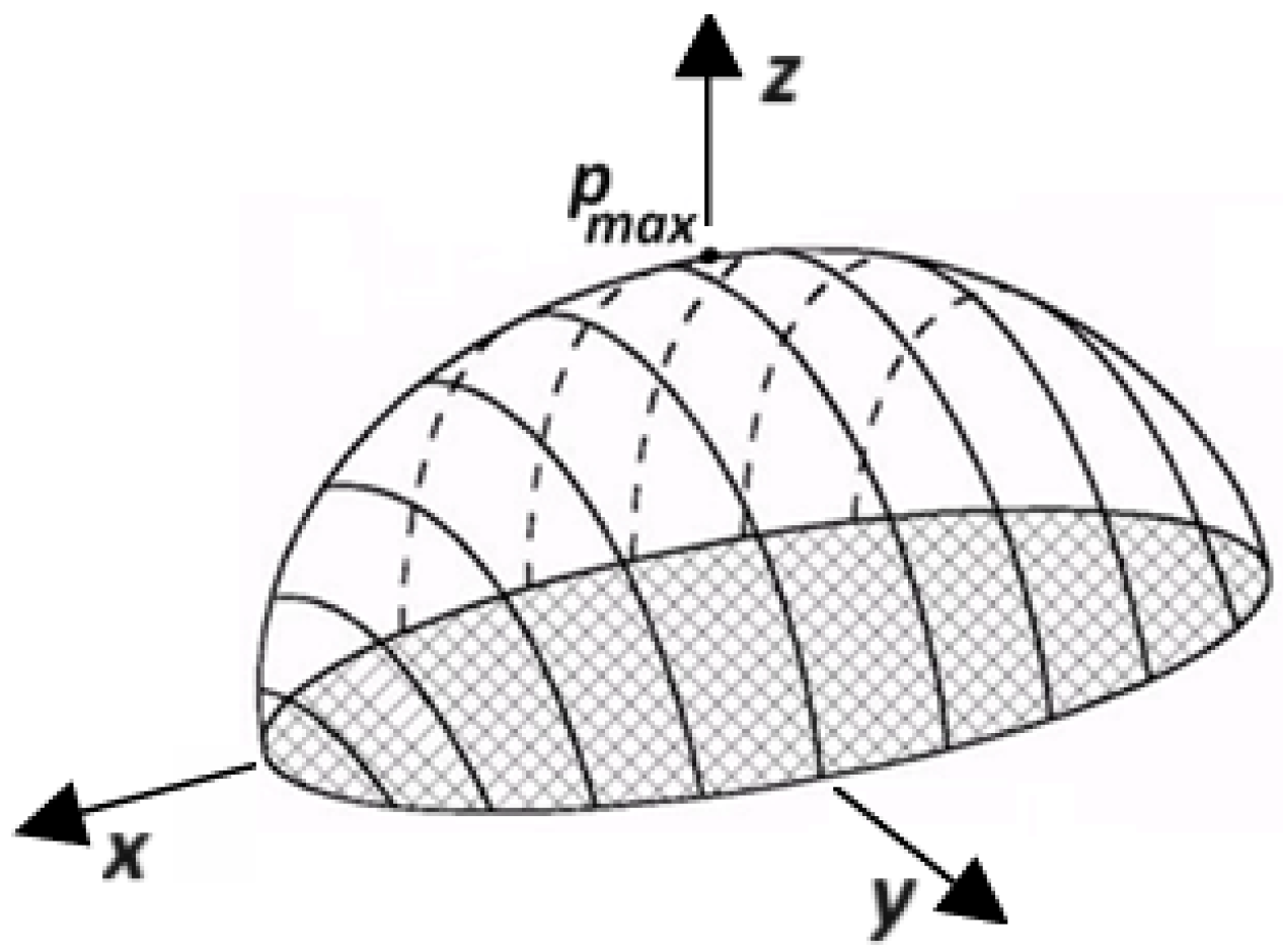
According to Hertz’s theory, under normal contact conditions (friction forces are neglected, and shear stresses on the contact area are absent), the distribution of contact pressure (Figure 2) on the elliptical area can be described as follows [16]:
p x , y = p m a x 1 x 2 a 2 y 2 b 2 , p m a x = 3 P 2 π a b ,
where a and b are the major and minor semi-axes of the ellipse along the principal axes x and y , respectively; P —is the resultant normal force.
The lengths of the ellipse axes are calculated using the formulas:
a = m 3 π 4 P K 1 + K 2 A + B 3 , b = n 3 π 4 P K 1 + K 2 A + B 3 .
Positive constants A ,   B are determined from the system of equations:
A + B = 1 2 1 r 11 + 1 r 12 + 1 r 22 + 1 r 21 , B A = 1 2 1 r 11 1 r 12 2 + 1 r 22 1 r 21 2 + 2 1 r 11 1 r 12 1 r 22 1 r 21 c o s 2 ψ 1 2 ,
where r 11 ,   r 12 ,   r 22 ,   r 21 —are the principal relative radii of curvature of the contacting surfaces. In the case of contact between a new rail and wheel,
r 11 = R w —the radius of curvature of the wheel at the contact point (nominal wheel radius at the rolling circle).
r 12 = r w —the radius of curvature of the wheel profile (for a conical profile r 12 );
r 22 = r r —the radius of curvature of the rail head at the contact point, r 21 for a straight rail in the vertical plane.
ψ —is the angle between the planes in which the principal radii of curvature r 11 ,   r 12 (for standard railway wheels with a conical profile ψ = 0 ).
For a railway wheel according to the DSTU 4835:2008 standard [22] and a rail according to the DSTU 4344:2004 standard [23] under central contact conditions: R w = 478.5   мм, r r = 500   мм. For the so-called conformal wheel profile [24], where the contour of the ridge zone (starting from the nominal rolling circle and ending with the radial transition to the ridge) is a mirror reflection of the corresponding part of the head of a moderately worn rail, r w = 514   мм.
The dimensions of the contact area depend on the relationship between the elastic properties of the wheel and rail materials. Therefore, coefficients are included in Formula (2):
K 1 = 1 υ 1 2 π E 1 , K 2 = 1 υ 2 2 π E 2 ,
where E 1 ,     E 2   are the moduli of elasticity, and υ 1 ,   υ 2   —are the Poisson’s ratios of the wheel and rail materials, respectively.
The coefficients m and n re related to the calculation of elliptical integrals and are determined by interpolation from tables [25], depending on the value of the parameter β , which is equal to
β = a r c c o s B A A B = a r c c o s 1 R w 1 r w 1 r r 1 R w + 1 r w + 1 r r .
At the center of the contact zone, the compressive normal stresses are as follows:
σ x = p m a x 2 ν + 1 2 ν b a + b ,     σ y = p m a x 2 ν + 1 2 ν a a + b , σ z = p m a x .
At the extreme points of the major axes of the ellipse (on the boundaries of the contact area), equal in magnitude positive radial and negative tangential stresses act:
σ x = σ y = p m a x 1 2 ν b a e 2 1 e A r t h e 1 ,   x = ± a   ,   y = 0 ; σ y = σ x = p m a x 1 2 ν b a e 2 1 b a e a r c t g a e b   ,   y = ± b   ,   x = 0 ,
where e = 1 b 2 a 2 —is the eccentricity of the ellipse.
The maximum shear stresses τ m a x will act at a point on the vertical axis z , passing through the center of the ellipse, at a certain distance from the surface of the bodies, depending on the value of the eccentricity e and the elastic properties of the material. The variation of τ m a x for b a = 0.6 and υ = 0.25 is illustrated by the data in Table 1 [26].
In strength calculations, the value of the stress intensity (Mises equivalent stress) is usually used:
σ e q v = 1 2 σ x σ y 2 + σ y σ z 2 + σ z σ x 2
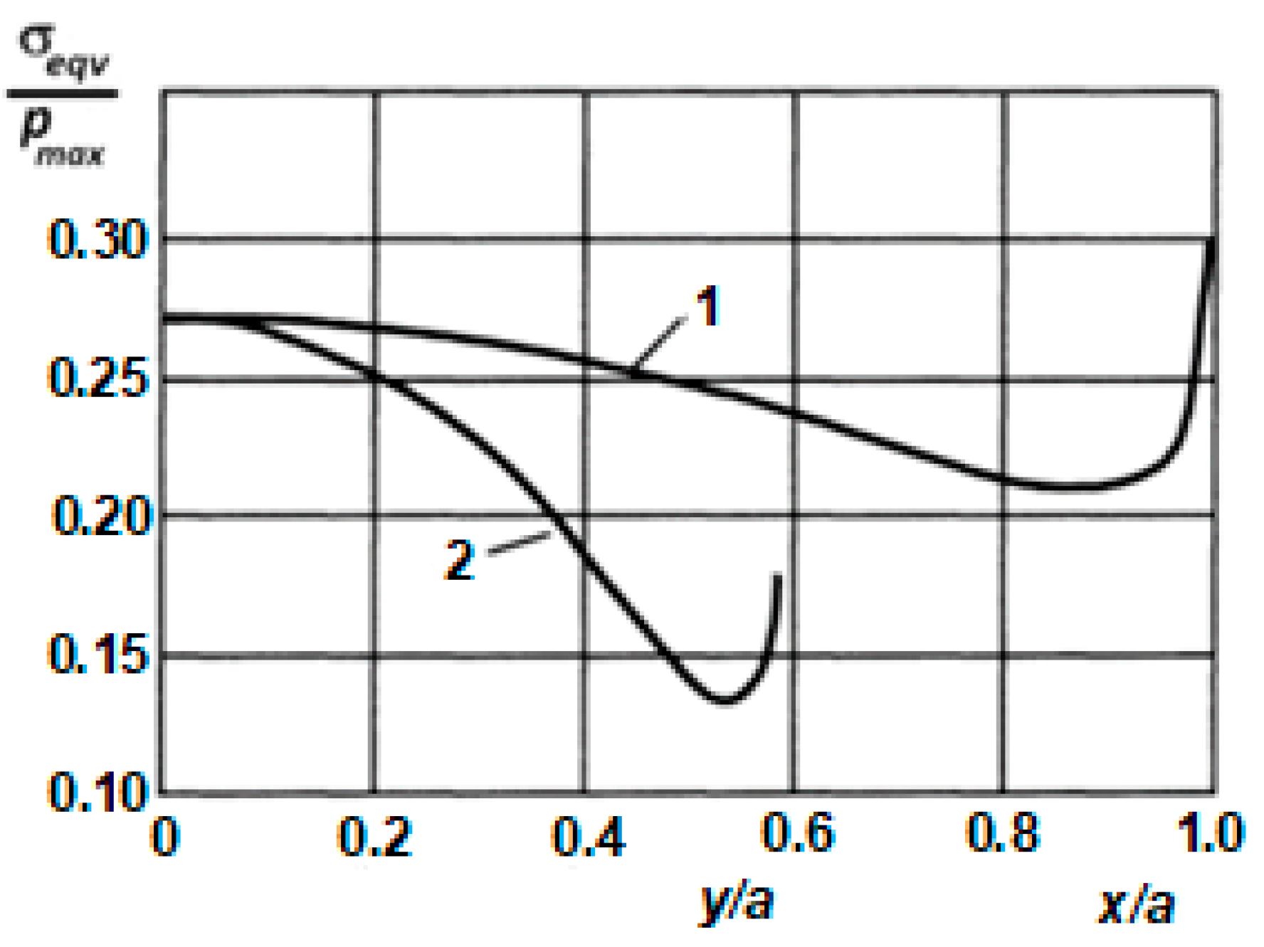
Figure 3 [26] illustrates how, under the above conditions, the relative equivalent stress σ e q v p m a x varies at points along the semi-axes of the ellipse.
From the presented data, it can be concluded that the highest stresses occur at the center of the ellipse and at a point on the ellipse’s boundary that is farthest from its center. At the center, all three principal stresses are compressive (although not necessarily equal in magnitude), while at the boundary, a plane stress state is realized with normal stresses of different signs. This aspect is crucial for understanding the formation of a crack network on the running surface (see Figure 1b).
During vehicle movement, the position of the wheelset relative to the rails, and hence the location of the contact area, constantly changes due to transverse oscillations of wagons and locomotives, wheelset imperfections, varying degrees of wear of wheels and rails, etc. Similarly, the directions of principal stresses and maximum shear stresses on the contact surfaces also change. For the surface material layers, which have exhausted their plastic properties, the level of these stresses may be sufficient to cause the formation of microcracks that will further develop through fatigue mechanisms.
Mathematical modeling of these processes is a rather complex task, even with the use of powerful numerical methods and modern computers, because many factors influencing the formation of surface microdefects are difficult to formalize and remain insufficiently studied experimentally (e.g., the distribution of residual technological stresses, material anisotropy and inhomogeneity, surface roughness, etc.).
Typically, when mathematically modeling this problem, the analysis is limited to the stress state at points where maximum stresses occur (at a certain depth beneath the center of the contact ellipse), as this is where internal cracks originate.
The Hertz theory is used to estimate the level of maximum contact stresses in strength calculations of parts of various shapes that come into contact with each other. The main limitation of this theory is the assumption of an elastic nature of interaction and the implementation of point contact. Nevertheless, the Hertz solution is often used to model surface loads when calculating contact stresses using numerical methods. This allows us to simplify and speed up the solution of many contact problems, especially spatial ones.
These calculations form the basis of many models for predicting contact-fatigue durability and wear of railway components [11,12,13,27,28,29,30,31,32]. Therefore, let us examine the features of constructing computational schemes for such problems.

2.2. Computational Schemes for Rails—Wheels Contact Problems

The success of solving contact interaction problems between rails and rolling stock wheels depends on the accuracy of the computational schemes, the choice of numerical method, software, and the computational power of the equipment. This explains why the results of different studies are often difficult to compare, not only quantitatively but sometimes even qualitatively. In this work, we will limit ourselves to considering the modeling of the stress state of rails using software implementing the finite element method.
Today, computing technology and available software for solving spatial contact problems have limited capabilities. Therefore, researchers have to use simplified versions of all components of the calculation scheme in problems of contact interaction of rails and wheels. Here, it is appropriate to recall A. Einstein’s statement: “Everything should be made as simple as possible, but not simpler.”
Notable examples are the first attempts at numerical modeling of such problems.
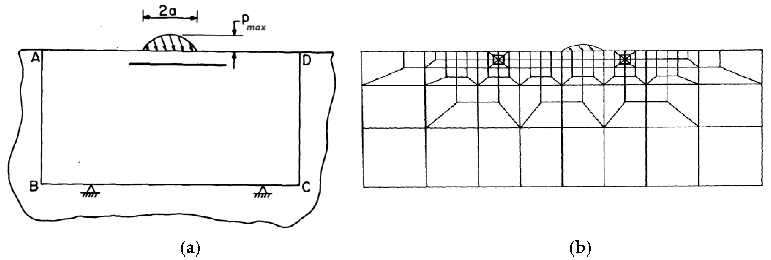
In works [33,34], a physical model of surface failure of bodies under friction conditions due to the initiation and growth of internal cracks was proposed. Given the computational limitations of that time, numerical modeling of this process was restricted to a plane problem (Figure 4a). For numerical modeling, the ADINA software package was used, and the finite element mesh is shown in Figure 4b.
These works continue to attract attention even today because they demonstrated that high-quality results can be obtained even with relatively simple computational schemes. However, it is clear that the accuracy of stress and deformation determination with such a sparse mesh is very low. Let us highlight some features of the computational scheme shown in Figure 4, which have been utilized in many subsequent works for calculating the stress–strain state of rails.
The first feature concerns the method of load application. In some works [11,27], a stationary load is defined, distributed over an elliptical contact area whose dimensions are determined by Formula (2), while the intensity of the distributed load is described by law (1). To improve calculation accuracy, the finite element mesh in the contact zones must be significantly refined (of course, taking into account the capabilities of computational equipment, as the number of calculations is estimated to grow exponentially with decreasing element size).
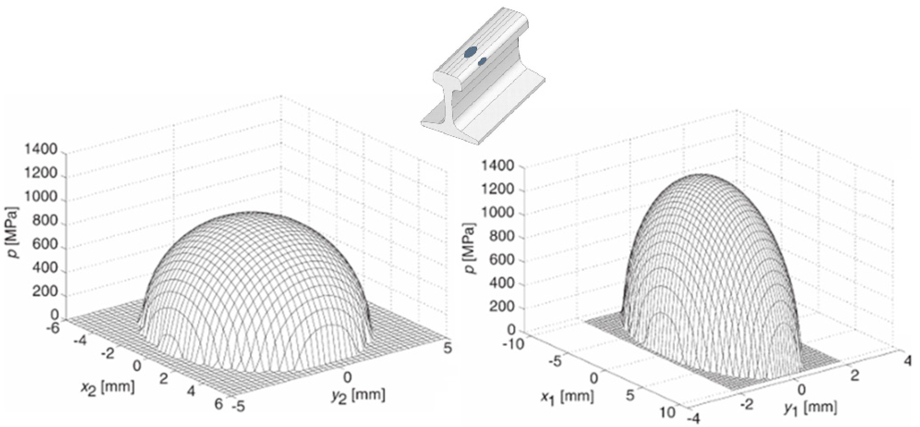
To apply the load, it is necessary to calculate the values of the contact pressure for the known coordinates of each mesh node within the elliptical contact area and define them as normal surface nodal forces. In works [11,27], a specialized program is used for this purpose. Figure 5 shows the distribution of contact pressures under conditions of a two-point contact between the wheel and rail on curved track sections [27].
One advantage of this method of load application is the ability to account for the influence of tangential forces that arise due to wheel slippage relative to the rails. Their nodal values can be calculated considering different coefficients of friction for rolling and sliding in longitudinal and transverse directions relative to the rail axis:
q x x , y = μ x p x , y ;   q y x , y = μ y p x , y ,
where q x x , y and q y x , y —are the magnitudes of tangential forces at the contact point with coordinates x , y ; μ x and μ y —are the coefficients of friction in the longitudinal and transverse directions, which may vary for each contact zone in the case of two-point contact.
This approach simplifies the solution of contact problems (especially in three-dimensional formulations) significantly but has some disadvantages that affect the accuracy of stress and deformation calculations for real wheel–rail friction pairs. It should be noted that this method can only be used when Hertzian theory conditions are satisfied. Therefore, it is not applicable to areas where conformal contact conditions exist (i.e., the initial contact occurs not at a point but over a sufficiently large area). This applies particularly to worn rails as well as certain combinations of profiles of new rails and wheels.
The main source of error in this method lies in its inability to account for the evolution of the contact patch as plastic deformations occur, which significantly impacts the calculated stress levels. Nonetheless, the simplicity of this scheme outweighs potential inaccuracies in contact stress calculations, which is why it is widely used for assessing the fatigue life of rails under conditions of rolling and sliding friction [11,27,28,29,32]. It should be noted, however, that such assessments, for the reasons mentioned above, are conservative in most cases.
The second feature of the computational scheme in Figure 4 is the refinement of the finite element mesh in stress concentration zones. Theoretically, the accuracy of stress calculations increases exponentially as element size decreases, so in practice, the number of elements often needs to be balanced against the capabilities of computational equipment. Under these circumstances, mesh refinement is performed only in the contact zones between rails and wheels. Optimal element sizes in the contact zone can be estimated by comparing calculated stress values with theoretical ones using Formulas (6 – 8) [30,35].
In work [35], it is noted that even for sufficiently refined meshes, errors may exceed 25%. Therefore, it is essential to ensure node consistency between finite element meshes on the contact surfaces. Often, the contact of two disks is considered as a model problem [11,30,35,36,37]. There is an exact analytical solution to this problem. This allows us to estimate the accuracy of the numerical solution and select the optimal parameters of the calculation scheme, for example, the degree of condensation of the finite element mesh. To achieve sufficient (<5%) accuracy in determining contact stresses, the average linear dimensions of elements, modeled as tetrahedrons, should not exceed 0.5 mm [30]. In this case, the calculated durability can be compared with experimental results, as this mechanical testing scheme is straightforward to implement and widely used.
The accuracy of stress level assessment in the wheel–rail contact zone depends not only on the degree of finite element mesh refinement. It is also necessary to take into account factors related to the track design, such as
  • The stiffness of the sub-rail foundation, which affects deflections and angles of the rail twisting under wheel loads;
  • The inclination of the rail base relative to the sub-rail foundation;
  • The degree of outer rail elevation in curved track sections;
  • Track gauge width;
  • The profiles of the contact surfaces.
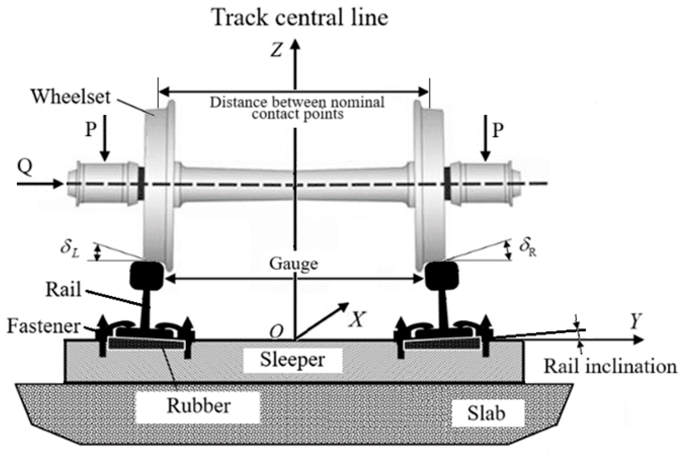
Incorporating these factors significantly complicates the computational scheme shown in Figure 6. Therefore, we will examine which of these factors should be prioritized and which can be considered secondary.
In most studies that attempted to calculate rail durability based on crack initiation criteria, the stresses from rail bending and torsion were not considered. Indeed, when comparing the levels of these stresses with contact stresses, the latter are significantly higher.
In work [38], based on the simplified method of calculating rails proposed in paper [39], the maximum compressive normal stresses in the head of a type R50 rail from bending and compressed torsion were calculated for a curved section of metro track with a 400 m radius. Even considering dynamic loading, these stresses did not exceed 100 MPa. The maximum equivalent contact stresses, calculated using the finite element method for a straight track section with the same rail type, were approximately 610 MPa at a depth of 3.12 mm [14]. Therefore, for tunnel track sections of metro systems, which exhibit high stiffness, the bending and torsion stresses can be neglected. Including these stresses may only affect the distribution of shear contact stresses τ y z and τ z x , whose magnitudes are approximately 200 MPa [14].
For tracks on wooden sleepers, which have significantly lower stiffness in the vertical plane, greater rail deflections will result in a slight decrease in contact stresses due to an increased contact area.
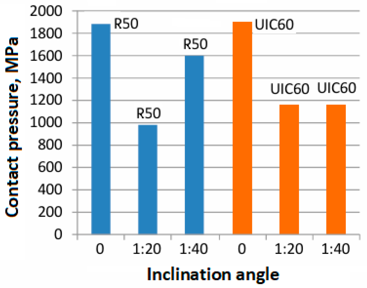
A significant factor affecting the level of contact stresses is the inclination angle of the rail base relative to the sub-rail foundation (rail inclination; see Figure 6), which is adjusted using special rubber pads. In Ukraine, the standard rail inclination value for railways with a gauge width of 1520 mm is 1:20. For European railways with a gauge width of 1435 mm, this angle can be 1:20, 1:30, or 1:40, depending on the country. The dependence of the maximum contact pressure on the rail inclination for two types of rails is shown in Figure 7. For UIC60 rails, the value of the contact pressure depends little on the rail inclination angle; only in the absence of a slope p m a x does it increase significantly.
In [14], it is shown that in the case of a single-point contact of a railway wheel according to DSTU 4835:2008 [22] with rails R50, R65 according to DSTU 4344:2004 [23], the use of a 1:20 rail inclination provides minimal contact stress values ~ 600 MPa (Figure 8).
This is due to the fact that there is no inclination of the conical part of the wheel rolling surface to the rail rolling surface and the condition δ L = δ R = 0 is fulfilled (see Figure 6). For nonlinear wheel profiles, the magnitude of contact stresses under these conditions increases significantly (up to 1020 MPa for a wheel with a conformal profile [24]), leading to the rapid wear of new rails. For UIC60 rails, the value of the contact stresses depends little on the rail inclination angle; only in the absence of a slope p m a x does it increase significantly (up to 1092 MPa).
The rail inclination can change due to the compression of pads, partial destruction of sleepers, fasteners, etc. If the rail inclinations in the track vary, the wheelset shifts toward the rail with a greater inclination angle. In this case, dynamic (impact) two-point contact occurs, with the contact patches located in the same transverse plane (see Figure 5). The absence of rail inclination significantly increases the level of contact stresses.
A similarly significant impact on contact stress levels is exerted by the magnitude of the outer rail elevation in curved track sections. In such cases, the inclination angles δ L and δ R (see Figure 6) will be different in magnitude and will not be equal to zero. Consequently, contact stress levels will increase on both rails. However, in this situation, the contact patches on the outer rail will be located in different transverse planes, with the distance between them depending on the track curvature radius. When calculating the influence of rail elevation on contact stress levels, it is necessary to consider the possible redistribution of wheel loads on the rails caused by unbalanced centrifugal acceleration and the eccentric position of the vehicle’s center of mass. This effect will be more pronounced for taller vehicles. However, the magnitude of this influence on the level of contact stresses remains an open question, as there are few examples of such calculations in the literature [40].
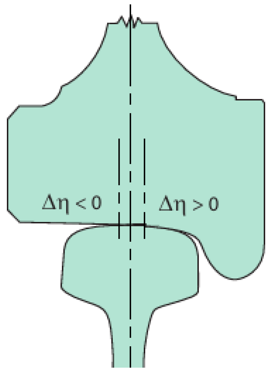
The position of the wheelset relative to the two rails in the track also affects contact stress levels, even on straight track sections. During movement, the bogie of the rolling stock undergoes transverse oscillations, leading to different combinations of wheel–rail contact zones. This results in changes in the size and shape of contact patches and, accordingly, significant variations in stress distribution. In certain cases, two-point contact with impact interaction between the flanges of the rolling stock wheels and the rails may occur. Works [41,42] present the results of mathematical modeling of the interaction between 60Е2 rails and wheels with S 1002 profiles. Calculations of contact stresses using the finite element method in the elastic formulation were performed for straight track sections with a rail inclination angle of 1:40 for two levels of static wheel loads: 60 and 90 kN. The possibility of lateral displacements of the wheel relative to the rail was also considered. The term “lateral displacement” refers to the distance η between the symmetry axis of the rail and the plane of the wheel’s rolling circle (Figure 9). Positive η values correspond to the rolling plane being to the right of the rail’s symmetry axis, while negative values indicate the lateral side of the rail approaching the wheel flange. For a nominal track gauge width of 1435 mm and a distance of 1425 mm between the inner faces of the wheelset flanges, the calculated lateral displacement is +3 mm from the neutral position of the wheelset relative to the track’s symmetry line. Lateral displacements of the wheelset relative to the track can range from +7.5 mm to −3 mm. At η = −3 two-point contact occurs as shown in Figure 5.
Figure 10 shows how the maximum normal stresses change depending on the magnitude of the wheelset’s lateral displacement relative to the track for two levels of wheel load. The figure also illustrates the calculated shapes of contact patches for several values of η (the sizes of the images are kept constant for convenience).
The data indicate that, as the rail’s lateral side approaches the wheel flange, the contact patch gradually loses its elliptical shape, and its area decreases by nearly 20%, while maximum stresses localize in a relatively small zone. The difference between the maximum stress values for different contact zones reaches 300 MPa, indicating a significant influence of track gauge width on contact stress levels.
Certain combinations of rail inclination, rail elevation in curves, and track gauge width can clearly be used to reduce contact stress levels. However, such analysis requires multivariate calculations for each pair of rail and wheel profiles.
Compatibility assessments of different rail and wheel types are presented in many studies [14,43,44,45,46,47,48,49]. The primary goal of such research is to select the optimal geometric dimensions and shapes of the working surfaces of rails and wheels. However, the set of optimization criteria is quite broad. In [44], profile compatibility is evaluated based on criteria such as
  • Contact should be single-point and conformal;
  • The rolling surfaces should have equivalent conicity that maximizes the wavelength of the bogie’s lateral oscillations and meets the requirements of the international standard UIC Code 519 [50].
In works [43,45,46,47,48,49], the optimality criterion is taken as the minimum value of equivalent stresses in the contact zone, a decrease in the wear rate of the rail and wheel material, or a decrease in the accumulation rate of contact fatigue damage. The data presented in these works show that the influence of the wheel–rail friction pair profiles is significant, and this factor should be taken into account first.
In [14], contact stresses were calculated for six combinations of R50, R65, and UIC60 rails with wheels having standard conical [22] and nonlinear wear-resistant [24] profiles. The smallest contact stresses ( σ e q v   ~ 600 MPa) were observed for R50 and R65 rails with a standard wheel, the largest ( σ e q v   ~ 1070 MPa) for the combination of R65 rail with a wheel having a nonlinear profile. It is obvious that an increase in the contact stresses will lead to a rapid accumulation of fatigue defects in new rails, especially for metro tracks with increased stiffness and small axial loads.
However, for worn rails on mainline tracks, this same combination, according to [51], is the most advantageous. In mountainous regions with small-radius curves, the standard profile is preferable [52]. The issue of choosing optimal profiles is very complex, if we take into account their gradual change during operation due to wear. Therefore, in most cases, recommendations for choosing “optimal” rail and wheel profiles will apply to homogeneous rolling stock and a certain track design. It should be noted that to assess the effectiveness of rail and wheel profiles, economic indicators related to the costs of grinding rails, turning wheel treads, and energy consumption for train traction should also be included [51,52]. However, a detailed analysis of the known approaches is beyond the scope of this work.
It is obvious that, in addition to the design parameters of the track, the level of contact stresses will also be influenced by the factors of the force interaction of rails and wheels. The analysis of theoretical and experimental methods for determining the forces of interaction of rolling stock with the railway track deserves a separate publication, since there are a lot of works in this direction. Let us mention only the excellent monographs [53,54,55], which have already become classics, as well as some review articles [56,57,58].
In a simplified form, the force interaction between rails and wheels in the case of single-point contact is shown in the scheme (Figure 11), which shows the resultant forces and moments that arise as a result of slipping, and which are actually distributed over the contact area.
Typically, the problem of the stress–strain state in the contact zone is solved in a quasi-static formulation, increasing the values of vertical, lateral, and longitudinal forces by dynamic coefficients, which are determined through modeling or experimentally using special vehicles with appropriate measuring equipment.
In dynamic models, the vehicle and track, excluding the rails, are considered rigid multi-mass systems. Rails are modeled either as beams on a continuous elastic foundation (Timoshenko beams) [59] or as discrete supports (sleepers) with random viscoelastic characteristics [60]. Comparisons of modeling results with experimental data at different speeds on real track sections show that vertical forces are modeled with good accuracy (the relative error, depending on speed, ranges from 1.2% to 23%) [61]. Such a large spread of relative error is due to the fact that such estimates were made for different operating conditions. In real conditions, spatial oscillations of rolling stock and track occur. These oscillatory processes are influenced by many factors that cannot be fully taken into account in discrete dynamic models. The worst modeling results were obtained for ordinary main railway lines, and the best for special ones (metro and test sites).
The accuracy of lateral force estimation is significantly lower, which, according to [62], is primarily due to discrepancies between modeled and actual wheel and rail profiles.

3. Results and Discussion

Railways with the corresponding infrastructure are the most important part of the transport industry in most countries. The problem of ensuring their safe operation and sustainable functioning and development is a complex and multifaceted task. The life cycle of a track, as one of the most important elements of the railway infrastructure, depends on many factors, which can be divided conditionally into several groups.
The factors influencing the external environment include daily temperature fluctuations, humidity, dustiness and others, which are associated with the climate zone, terrain characteristics, and soil. The influence of such factors (for example, changes in climatic conditions and large-scale natural disasters) can be spontaneous and difficult to foresee, and even more difficult to predict their impact on the life cycle of a track [63].
Organizational factors include the quality of management, the level of automation on the railway, professional training of personnel, traffic, the organization and volumes of passenger and freight transportation, as well as their documentation, excess loads of trains, the availability of modern lubrication equipment, etc. Only some of the listed factors can be formalized and used as parameters of mathematical models for resource forecasting. It is sometimes quite difficult to foresee the consequences of some management decisions related to the organization of railway transportation or the implementation of railway construction and reconstruction projects [64]. Economic factors (affiliation with private, joint-stock or state structures, the volume and distribution of financing, etc.) are closely related to organizational factors and have a significant impact on the development of railways.
The factors combined into the operational group, unlike those listed above, are mostly subject to formal description and their influence can be modeled, which allows the improvement of the methods of predicting the life cycle of the track. These include the geometric characteristics of the elements of the track superstructure, the design features of the rolling stock, the physical and mechanical characteristics of the main materials, train movement modes, and others [29,30,31,32,36,37,38,43,44,52,65,66]. The influence of these factors can be assessed by means of natural, laboratory, and numerical experiments.
To conduct field experiments on existing road sections, it is necessary to obtain permission from the administration, since this is related to traffic safety and often to changes in traffic. In addition, such experiments can last for several months and are often very expensive. Difficulties in conducting laboratory experiments are often associated with the impossibility of reproducing the operating conditions of individual structural elements with sufficient accuracy. For example, many methods are used to assess the level and nature of contact stress distribution: electrical tensometry, the coordinate grid method, polarization-optical methods, methods of applying brittle or optically transparent coatings, hardness measurements, and others. However, all of them provide only qualitative results. Therefore, at present, increasing the accuracy of predicting the durability and residual life of railway infrastructure elements is associated mainly with the use of numerical calculation methods.
To obtain reliable results in numerical modeling of the contact interaction of the wheel and rail, it is important to correctly specify or formulate all components of the finite element method calculation scheme—a geometric model, a model of force and kinematic conditions, and a model of physical and mechanical properties of the material. In order to take into account, the main design features of the upper track structure, namely the rail inclination angle, track width, and the elevation of the outer rail in curves, it is necessary to consider a sufficiently complete geometric model of the track, which contains the entire wheel pair, which rests on two rail threads (see Figure 6). Additionally, such a model can be used to assess the influence of the stiffness of the sub-rail base on the level of contact stresses. However, if the sub-rail base is considered as completely elastic, then a change in its stiffness has little effect on the level of maximum contact stresses [63]. A significant effect can be if there is a local change in stiffness (for example, due to the destruction of the sleeper). But for this, the sub-rail base should be considered unequally elastic [60], which significantly complicates the calculations. The indicated scheme (see Figure 6) will also be useful for assessing the influence of the bending stiffness of the rolling stock bogie axis on the stressed state of the rail. Significant bending of the bogie axis in the vertical plane can change the position of the contact points of the wheels with the rails, and this will affect the level of contact stresses.
For quasi-static stress analysis of rails on straight track sections, external vertical P and lateral Q forces should be applied to the bogie axis (see Figure 6). In this case, there will be three or two contact zones (in the case of conformal profiles or when Q = 0). Solving such a problem requires quite powerful computers, so it is often limited to considering the right half of the calculation scheme in Figure 6. However, in this case, the analysis of the influence of the above-mentioned design factors is significantly complicated and, in most cases, only approximate results can be obtained.
The results of calculations by various authors, given in Section 2.2, show that the above-mentioned track design parameters must be taken into account first in the calculations of the stress state of the rails.
Within the framework of one publication, it is impossible to consider other extremely important factors that affect the accuracy of the assessment of the level of contact stresses. Such factors include the initial distribution of technological stresses, mechanical properties of the wheel and rail materials, the magnitude and nature of the change in axial and lateral loads, consideration of friction, anisotropy of materials, temperature, etc. These issues are somehow related to the formulation of the physical model of the finite element method. In such cases, it is advisable to first consider the contact interaction using 2D and 3D fragments of the wheel and rail in order to obtain high-quality results. Such an approximate formulation of the contact problem is advisable to use for modeling surface plastic deformation under conditions of rolling with slipping, analyzing the influence of surface roughness on the stress–strain state of surface layers of parts, stress concentration on defects (inclusions and microcracks) of the material, etc. The authors plan to consider these aspects in subsequent publications.

4. Conclusions

Forecasting contact fatigue endurance, wear and destruction of railway rails and wheels of rolling stock is based on estimates of the stress–strain state of parts, which is associated with the need to solve boundary value problems of contact interaction. Such calculations are also necessary for understanding the physical processes of damage accumulation, the occurrence and development of defects in rails and wheels. These processes are influenced by many factors, which can be conditionally divided into three groups—structural (geometric parameters of the rail and wheel, types of fasteners, types of sleepers, rail inclination angles, rail elevation in curves, track width, etc.), technological (material, heat treatment, residual stresses, wheel and rail hardness ratio, etc.), and operational (speed, slippage, temperature, lubrication, etc.).
The complexity of the comprehensive analysis of the influence of the specified groups of factors is associated with the synergistic effects of their action, and therefore such an analysis is very complex and requires multivariate calculations. In this work, the authors deliberately limited themselves to considering the influence of only some design parameters of the rail track and wheels on the magnitude and distribution of stresses in the contact zone.
This work presents the basic formulas for a simplified analytical solution to the contact problem based on Hertz’s theory, which is still widely used in many regulatory documents to assess the magnitude of stresses in the contact of parts for various purposes, including rails and wheels.
The modern approach to solving contact problems is to use numerical methods, in particular, the finite element method (FEM). When using numerical methods, the accuracy of calculating the stress–strain state depends on several factors: software capabilities, computer processing power, and the accuracy of the calculation scheme. The FEM calculation scheme consists of a geometric model, a model of force and kinematic conditions, and a model of physical and mechanical properties of the material.
In this work, the main attention is paid to the consideration of the features of constructing a geometric model of the MSE, which would allow assessing the influence of some factors related to the design of the track (in particular, the rigidity of the sub-rail base, the inclination of the rail sole to the sub-rail base, the amount of elevation of the outer rail in curved sections of the track, the track width and the profiles of the contact surfaces) on the magnitude of the contact stresses. This possibility is provided only by a sufficiently complete geometric model, which is shown in Figure 6. Consideration of the contact interaction using 2D and 3D fragments of the wheel and rail gives only qualitative results; therefore, such problems should be used for modeling surface plastic deformation under conditions of rolling with slipping, analyzing the influence of surface roughness on the stress–strain state of the surface layers of parts, stress concentrations on defects (inclusions and microcracks) of the material, etc.
It is obvious that the level of contact stresses can be controlled to some extent by using certain combinations of rail inclination, rail elevation in curves, and wheel and rail profiles. These issues should be reflected in new editions of regulatory documents related to the design of railway infrastructure elements.
At present, it is problematic to expect from such contact interaction models results that would exactly correspond to the real stresses in the wheel–rail pair. In this work, the influence of only five different design parameters on the magnitude of contact stresses was estimated. The use of superposition methods to assess the joint influence of these factors is currently impossible, since contact problems are nonlinear even for elastic materials. Therefore, the search for optimal values of the factors considered in the work is a very difficult task from a mathematical point of view.
Future progress in this issue will be associated with the use of artificial intelligence methods. Thus, in work [67], an artificial neural network was used to find the position of the contact points of bodies. To train the network, equilibrium configurations of elastic bodies of various geometric shapes and sizes were calculated. To calculate such configurations, the condition of the minimum potential energy of the system of bodies was used. In this case, certain restrictions for the implementation of contact were taken into account, which follow from Hertz’s theory (see Section 2.1).
In the works [21,68], artificial intelligence models are used to estimate the friction coefficients in the contact of surfaces of real materials that have a certain roughness. As is known, the real contact area differs significantly from the nominal one; therefore, the average value of the coefficient of static friction will depend on the microrelief of the contacting surfaces, as well as on the mechanical properties of the surface layers of the material. In the indicated works, artificial neural networks were trained both on experimentally obtained profiles of real surfaces and on artificially generated models of rough surfaces. Experimental data on hardness, contact pressure, contact spot shape, friction coefficients, etc., can be added to such surface models. Also, such a network can be linked to the results of calculations of contact problems using the finite element method. Therefore, the rational accumulation of experimental and computational data on the estimation of the magnitude and distribution of contact stresses will allow creating the necessary knowledge base for training neural networks. In the future, such intelligent systems can be used to estimate contact stresses in rails and wheels of rolling stock. This will allow for more precise estimates of rail and wheel durability, as well as to assess the combined impact of the factors considered in this article on these estimates. Such models can be useful for finding ways to constructively and technologically improve the railway track in order to increase the durability of its life cycle and ensure the safe and sustainable operation of railway transport.

Author Contributions

Conceptualization, V.T. and O.B.; methodology, V.K.; validation, V.K., V.T. and O.B.; formal analysis V.T. and O.B.; investigation, V.K.; resources, V.T.; data curation, V.K.; writing—original draft preparation, V.K., V.T. and O.B.; writing—review and editing, V.K., V.T. and O.B.; visualization, O.B. All authors have read and agreed to the published version of the manuscript.

Funding

This work is supported by AGH University of Science and Technology under research program No. 16.16.130.942.

Institutional Review Board Statement

Not applicable.

Informed Consent Statement

Not applicable.

Data Availability Statement

The data is contained in the article and in the cited sources. No permission from third parties is required for the publication of the data provided.

Conflicts of Interest

The authors declare no conflict of interest.

References

  1. Elkhoury, N.; Hitihamillage, L.; Moridpour, S.; Robert, D. Degradation Prediction of Rail Tracks: A Review of the Existing Literature. Open Transp. J. 2018, 12, 88–104. [Google Scholar] [CrossRef]
  2. Semaan, N.; Zayed, Т. An assessment model for structural performance of subway systems. Int. J. Sci. Environ. Technol. 2014, 3, 1943–1968. [Google Scholar]
  3. Shur, E.A. Quality, Service Failure Rate, and Prospects of Rail Perfection. In Proceedings of the Internationales Symposium “Schienenfehler” Tagungsbericht, Brandenburg an der Havel, Germany, 16–17 November 2000; pp. 6-1–6-10. [Google Scholar]
  4. INNOTRACK Project No. TIP5-CT-2006-031415O. D4.1.4-Rail Degradation Algorithms. December 2009; 40p. Chalmers Railway Mechanics. Available online: https://www.charmec.chalmers.se/innotrack/deliverables/sp4/d414-f3-rail_degradation_algorithms.pdf (accessed on 2 March 2025).
  5. Edel, K.-O.; Budnitzki, G.; Schnitzer, T. Schienenfehler. Beanspruchung und Schädigung von Eisenbahnschienen; Springer Vieweg: Wiesbaden, Germany, 2021; 606p. [Google Scholar]
  6. Magel, E.E. Rolling Contact Fatigue: A Comprehensive Review; Technical Report 11/24; U.S. Department of Transportation, Federal Railroad Administration, Office of Railroad Policy and Development: Washington, DC, USA, 2011; 132p.
  7. Track Inspector Rail Defect Reference Manual; U.S. Department of Transportation, Federal Railroad Administration, Office of Railroad Safety: Washington, DC, USA, 2015; Revision 2; 82p.
  8. Olver, A.V. The mechanism of rolling contact fatigue: An update. Proc. Inst. Mech. Engng. Part J J. Eng. Tribol. 2005, 219, 313–330. [Google Scholar] [CrossRef]
  9. Edel, K.-O. Systematisierung der Schienenfehler. In Proceedings of the Internationales Symposium “Schienenfehler” Tagungsbericht, Brandenburg an der Havel, Germany, 16–17 November 2000; pp. 1-1–1-15. [Google Scholar]
  10. UIC Code 712. In Rail Defects, 4th ed.; International Union of Railways: Paris, France, 2002; 107p, ISBN 2-7461-0341-9.
  11. Ringsberg, J.W. Life prediction of rolling contact fatigue crack initiation. Int. J. Fatigue 2001, 23, 575–586. [Google Scholar] [CrossRef]
  12. Zwierczyk, P.T.; Váradi, K. Frictional contact FE analysis in a railway wheel-rail contact. Period. Polytech. Mech. Eng. 2014, 58, 93–99. [Google Scholar] [CrossRef]
  13. Sladkowski, A.; Sitarz, M. Analysis of wheel-rail interaction using FE software. Wear 2005, 258, 1217–1223. [Google Scholar] [CrossRef]
  14. Kosarchuk, V.V.; Danilenko, É.I.; Agarkov, A.V. Effect of railcar wheel tire profiles on the contact stress level in subway rails. Strength Mater. 2020, 52, 398–406. [Google Scholar] [CrossRef]
  15. Trummer, G.; Marte, C.; Scheriau, S.; Dietmaier, P.; Sommitsch, C.; Six, K. Modelling wear and rolling contact fatigue: Parametric study and experimental results. Wear 2016, 366–367, 71–77. [Google Scholar] [CrossRef]
  16. Johnson, K.L. Contact Mechanics; Cambridge University Press: Cambridge, UK, 1985; 452p, ISBN 978-0-521-25576-9. [Google Scholar]
  17. Aleshin, V.V. On Applications of Semi-Analytical Methods of Contact Mechanics. Front. Mech. Eng. 2020, 6, 30. [Google Scholar] [CrossRef]
  18. Telliskivi, T.; Olofsson, U. Contact mechanics analysis of measured wheel-rail profiles using the finite element method. J. Rail Rapid Transit. 2000, 215, 65–72. [Google Scholar] [CrossRef]
  19. Pohrt, R.; Li, Q. Complete Boundary Element Formulation for Normal and Tangential Contact Problems. Phys. Mesomech. 2014, 17, 334–340. [Google Scholar] [CrossRef]
  20. Wang, Q.; Sun, L.; Zhang, X.; Liu, S.; Zhu, D. FFT-Based Methods for Computational Contact Mechanics. Front. Mech. Eng. 2020, 6, 61. [Google Scholar] [CrossRef]
  21. Kalliorinne, K.; Larsson, R.; Pérez-Ràfols, F.; Liwicki, M.; Almqvist, A. Artificial Neural Network Architecture for Prediction of Contact Mechanical Response. Front. Mech. Eng. 2021, 6, 579825. [Google Scholar] [CrossRef]
  22. DSTU GOST 4835:2008; Cars Wheelsets of Mainline Railway Cars with a Gauge of 1520 mm. Derzhspozhyvstandart: Kyiv, Ukraine, 2008; 14p.
  23. DSTU 4344:2004; Ordinary Rails for Broad Gauge Railways. Derzhspozhyvstandart: Kyiv, Ukraine, 2005; 28p.
  24. Kozlovsky, A.; Taran, Y.; Staroseletsky, M.; Esaulov, V.; Gubenko, S.; Sładkowski, A.; Shramko, A. Improvement of Profiles of the Working Surface for Carload and Locomotive Wheels. In Proceedings of the Vth International Science Conference for Middle and Eastern European Countries, Katowice, Poland, 3–5 July 2002. 7p. [Google Scholar]
  25. Cooper, D.H. Tables of Hertzian Contact-Stress Coefficients; Report R-3R7; University of Illinois, Coordinated Science Laboratory: Urbana, IL, USA, 1968; 34p. [Google Scholar]
  26. Lundberg, G.; Sjövall, H. Stress and Deformation in Elastic Solids; Publ. No. 4; Institute of Theory of Elasticity, Chalmers University of Technology: Göteborg, Sweden, 1958. [Google Scholar]
  27. Ringsberg, J.W.; Josefson, B.L. Finite element analyses of rolling contact fatigue crack initiation in railheads. Proc. Inst. Mech. Eng. Part F J. Rail Rapid Transit. 2001, 215, 243–259. [Google Scholar] [CrossRef]
  28. Urassa, P.; Habte, H.S.; Mohammedseid, A. Crack influence and fatigue life assessment in rail profiles: A numerical study. Front. Built Environ. 2023, 9, 1304557. [Google Scholar] [CrossRef]
  29. Wang, Y.; Xiao, H.; Zhang, Z.; Cui, X.; Chi, Y.; Nadakatti, M. The formation, development and classification of rail corrugation: A survey on Chinese metro. Railw. Eng. Sci. 2025, 33, 43–61. [Google Scholar] [CrossRef]
  30. Krishna, V.V.; Hossein-Nia, S.; Casanueva, C.; Stichel, S.; Trummer, G.; Six, K. Rail RCF damage quantification and comparison for different damage models. Rail. Eng. Sci. 2022, 30, 23–40. [Google Scholar] [CrossRef]
  31. Zhang, S.; Liu, Q.; Spiryagin, M.; Wu, Q.; Ding, H.; Wen, Z.; Wang, W. Gaps, challenges and possible solution for prediction of wheel–rail rolling contact fatigue crack initiation. Railw. Eng. Sci. 2023, 31, 207–232. [Google Scholar] [CrossRef]
  32. Jaifu, A.; Raeon, S.; Pimsarn, M. Study of fatigue crack initiation location of wheel and rail under rolling contact using finite element method. MATEC Web Conf. 2018, 192, 02012. [Google Scholar] [CrossRef]
  33. Suh, N.P. The delamination theory of wear. Wear 1973, 25, 111–124. [Google Scholar] [CrossRef]
  34. Suh, N.P.; Sin, H.-C. Surface Traction and Crack Propagation in Delamination Wear; Report LMP/TRB-81-03; Laboratory for Manufacturing and Productivity, School of Engineering, Massachusetts Institute of Technology: Cambridge, MA, USA, 1981; 188p. [Google Scholar]
  35. Esaulov, V.P.; Sladkovskii, A.V. Determination of the digitizing errors generated in the finite-element computation of railway wheels. Strength Mater. 1990, 22, 740–743. [Google Scholar] [CrossRef]
  36. INNOTRACK Report D 4.3.5 “Simulation of Materials Deformation and RCF”. 2009; 43p. Chalmers Railway Mechanics. Available online: https://www.charmec.chalmers.se/innotrack/deliverables/sp4/d435-f3-simulation_material_deformation_rcf.pdf (accessed on 2 March 2025).
  37. Liu, B.; Stefano, B. Analysis of Wheel-Roller Contact and Comparison with the Wheel-Rail Case. Urban Rail Transit. 2015, 1, 215–226. [Google Scholar] [CrossRef]
  38. Kosarchuk, V.; Aharkov, О.; Tverdomed, V. Life assessment of rails by criterion of occurrence of fatigue cracks. Transp. Syst. Technol. 2021, 38, 194–200. [Google Scholar] [CrossRef]
  39. van Belkom, A. A simplified method for calculating load distribution and rail deflections in track, incorporating the influence of sleeper stiffness. Adv. Struct. Eng. 2020, 23, 2358–2372. [Google Scholar] [CrossRef]
  40. Sun, L.P.; Zhang, J.; Zhang, J. Analyses on Wheel-Rail Contact Using Finite Element Method during Passing through Curved Track. In Proceedings of the International Conference on Measuring Technology and Mechatronics Automation, Zhangjiajie, China, 11–12 April 2009; pp. 728–731. [Google Scholar] [CrossRef]
  41. Kleiner, O.; Schindler, C. Untersuchungen zur Beanspruchung von Rad und Schiene. EI-Der Eisenbahningenieur 2009, 60, 12–18. [Google Scholar]
  42. Kleiner, O.; Schindler, C. Geometrie und Druckspannungen im Rad/Schiene-Kontakt. EI-Der Eisenbahningenieur 2011, 62, 9–12. [Google Scholar]
  43. Bogojević, N.; Lučanin, V.; Tatić, B. Influence of wheel profiles on rolling contact fatigue and wear rate of railway wheels. Mech. Transp. Commun. 2013, 11, VI-34–VI-40. [Google Scholar]
  44. Gerlici, J.; Lack, T. Contact geometry influence on the rail/wheel surface stress distribution. Рrocedia Eng. 2010, 2, 2249–2257. [Google Scholar] [CrossRef]
  45. Choi, H.Y.; Lee, D.H.; Song, C.Y.; Lee, J. Optimization of rail profile to reduce wear on curved track. Int. J. Precis. Eng. Manuf. 2013, 14, 619–625. [Google Scholar] [CrossRef]
  46. Jahed, H.; Farshi, B.; Eshraghi, M.A.; Nasr, A. A numerical optimization technique for design of wheel profiles. Wear 2008, 264, 1–10. [Google Scholar] [CrossRef]
  47. Wang, J.; Ren, Z.; Chen, J.; Chen, L. Study on Rail Profile Optimization Based on the Nonlinear Relationship between Profile and Wear Rate. Math. Probl. Eng. 2017, 2017, 6956514. [Google Scholar] [CrossRef]
  48. Magel, E.E.; Kalousek, J. The application of contact mechanics to rail profile design and rail grinding. Wear 2002, 253, 308–316. [Google Scholar] [CrossRef]
  49. Ye, Y.; Sun, Y.; Dongfang, S.; Shi, D.; Hecht, M. Optimizing wheel profiles and suspensions for railway vehicles operating on specific lines to reduce wheel wear: A case study. Multibody Syst. Dyn. 2021, 51, 91–122. [Google Scholar] [CrossRef]
  50. UIC Code 519: Method for Determining the Equivalent Conicity; Ed. No 1; International Union of Railways: Paris, France, 2004; 99p.
  51. Blokhina, G.S. Criterion of Economic Efficiency of Introduction of Railway Wheels with New Profiles of Rolling Surface. Probl. Increasing Effic. Infrastruct. 2001, 5, 16–20. [Google Scholar]
  52. Korotenko, M.L.; Zabolotny, O.M.; Neduzha, L.O.; Nesterenko, N.M.; Yagoda, D.O. Experimental study of wear of tires of VL11M electric locomotives with different profiles. Bull. Dnipropetr. Natl. Univ. Railw. Transp. Named After Acad. V. Lazaryan 2005, 8, 53–57. [Google Scholar] [CrossRef]
  53. Garg, V.K.; Dukkipati, R.V. Dynamics of Railway Vehicle Systems; Academic Press: Orland, CA, USA, 1984; 407p. [Google Scholar] [CrossRef]
  54. Kalker, J.J. Three-Dimensional Elastic Bodies in Rolling Contact; Kluwer Academic Publishers: Dordrecht, The Netherlands, 1990; 314p. [Google Scholar] [CrossRef]
  55. Iwnicki, S. (Ed.) Handbook of Railway Vehicle Dynamics; Taylor & Francis Group, LLC: Boca Raton, FL, USA; London, UK; New York, NY, USA, 2006. [Google Scholar] [CrossRef]
  56. Sharma, R.C. Recent Advances in Railway Vehicle Dynamics. Int. J. Veh. Struct. Syst. 2012, 4, 52–63. [Google Scholar] [CrossRef]
  57. Knothe, K. History of wheel/rail contact mechanics from Redtenbacher to Kalker. Veh. Syst. Dyn. 2008, 46, 49–66. [Google Scholar] [CrossRef]
  58. Eickhoff, B.M.; Evans, J.R.; Minnis, A.J. A review of modelling methods for railway vehicle suspension components. Veh. Syst. Dyn. 1995, 24, 469–496. [Google Scholar] [CrossRef]
  59. Wen, Z.; Xiao, G.; Xiao, X.; Jin, X.; Zhu, M. Dynamic vehicle–track interaction and plastic deformation of rail at rail welds. Eng. Fail. Anal. 2009, 16, 1221–1237. [Google Scholar] [CrossRef]
  60. Darenskiy, A.; Vitolberg, V.; Fast, D.; Klymenko, A.; Leibuk, Y. A mathematical model of the rail track presented as a bar on elastic and dissipative supports under the influence of moving loads. MATEC Web Conf. 2017, 116, 03002. [Google Scholar] [CrossRef]
  61. Sun, Y.Q.; Cole, C.; Spiryagin, M. Monitoring vertical wheel–rail contact forces based on freight wagon inverse modelling. Adv. Mech. Eng. 2015, 7. [Google Scholar] [CrossRef]
  62. Xia, F.; Cole, C.; Wolfs, P. Wheel rail contact forces prediction and validation with field tests. In Proceedings of the Conference on Railway Engineering, Perth, Australia, 7–10 September 2008; pp. 73–82. [Google Scholar]
  63. Palin, E.J.; Stipanovic Oslakovic, I.; Gavin, K.; Quinn, A. Implications of climate change for railway infrastructure. WIREs Clim. Chang. 2021, 12, e728. [Google Scholar] [CrossRef]
  64. Senić, A.; Dobrodolac, M.; Stojadinović, Z. Development of Risk Quantification Models in Road Infrastructure Projects. Sustainability 2024, 16, 7694. [Google Scholar] [CrossRef]
  65. Sharma, S.K.; Kumar, A. Ride performance of a high-speed rail vehicle using controlled semi active suspension system. Smart Mater. Struct. 2017, 26, 055026. [Google Scholar] [CrossRef]
  66. Gallyamov, D.I.; Ovchinnikov, D.V. Effects of rail canting on the contact stress and pressure in the wheel–rail system. Russ. Railw. Sci. J. 2023, 82, 9–17. [Google Scholar] [CrossRef]
  67. Goodbrake, С.; Motiwale, S.; Sacks, M.S. A neural network finite element method for contact mechanics. Comput. Methods Appl. Mech. Eng. 2024, 419, 116671. [Google Scholar] [CrossRef]
  68. Tanzim, N.; Nbhan, S.; Liew, T.H.; Chin, C.W.; Yousif, B.F. ANN for Tribological Applications. In Proceedings of the ASME International Mechanical Engineering Congress and Exposition, Lake Buena Vista, FL, USA, 13–19 November 2009; Paper No 10161. pp. 13–16. [Google Scholar] [CrossRef]
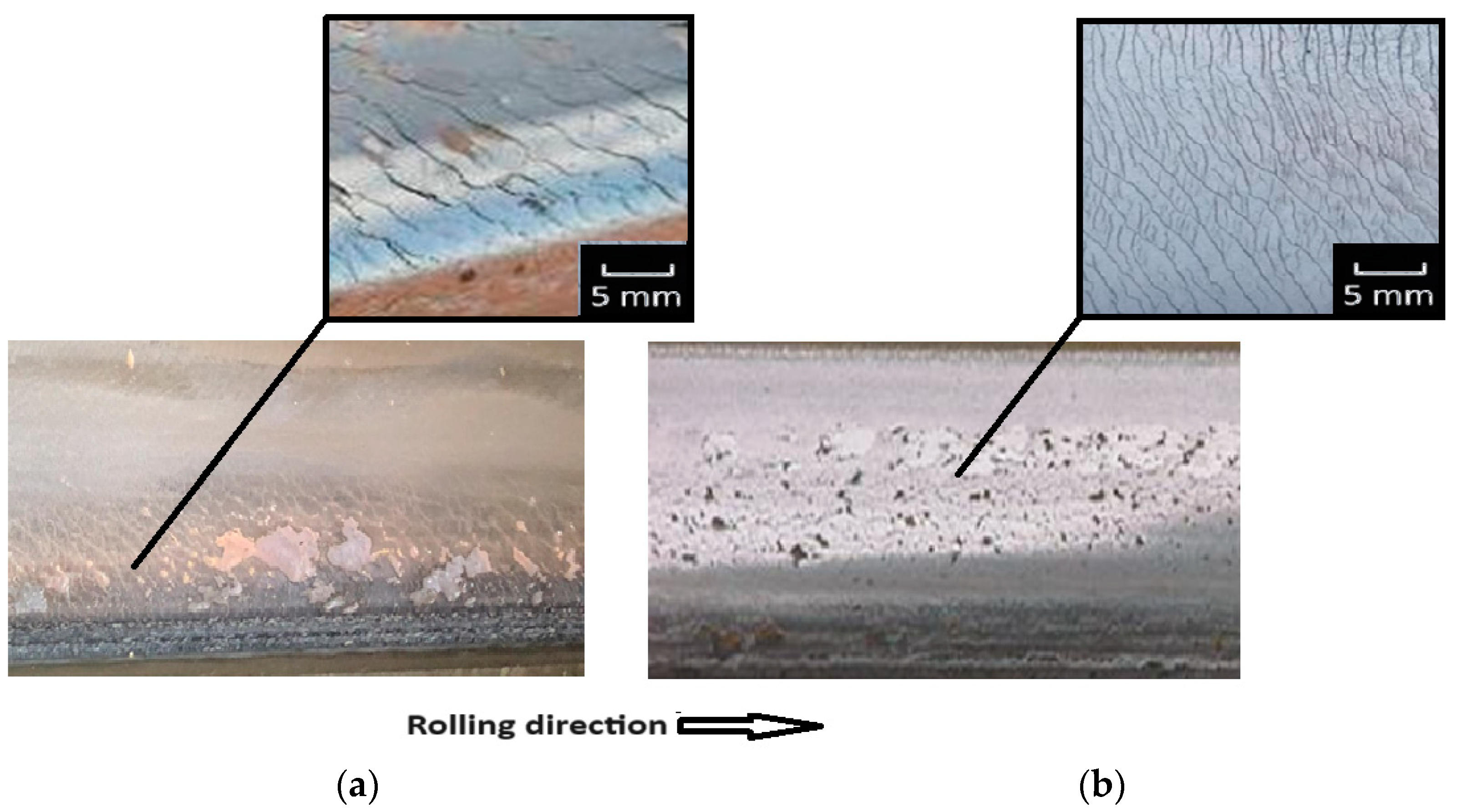
Figure 1. Surface microcracks on rails of the Kyiv Metro in curved track sections: (a) on the lateral side of the rail; (b) in the central part of the rail head.
Applsci 15 02970 g001
Figure 2. Distribution of normal pressure on the contact area.
Applsci 15 02970 g002
Figure 3. Graphs showing the variation in relative equivalent stresses at points along the major (1) and minor (2) semi-axes of the ellipse.
Applsci 15 02970 g003
Figure 4. Loading scheme (a) and finite element model (b) of the problem [34].
Applsci 15 02970 g004
Figure 5. Distribution of normal pressure under two-point contact conditions.
Applsci 15 02970 g005
Figure 6. Refined computational scheme for the interaction of rails with rolling stock wheels.
Applsci 15 02970 g006
Figure 7. Dependence of contact pressure on rail inclination.
Applsci 15 02970 g007
Figure 8. Dependence of contact stresses on rail inclination.
Applsci 15 02970 g008
Figure 9. Scheme for measuring the lateral displacement of the wheelset.
Applsci 15 02970 g009
Figure 10. Dependence of maximum normal stresses on the magnitude and direction of wheel lateral displacement relative to the rail.
Applsci 15 02970 g010
Figure 11. Force interaction scheme of a wheel and rail.
Applsci 15 02970 g011
Table 1. Dependence τ m a x p m a x on the size of the contact patch and the distance from the surface.
b a 00.20.40.60.81.0
z b 0.7850.7450.6650.5900.5300.480
τ m a x p m a x 0.3000.3220.3250.3230.3170.310
Disclaimer/Publisher’s Note: The statements, opinions and data contained in all publications are solely those of the individual author(s) and contributor(s) and not of MDPI and/or the editor(s). MDPI and/or the editor(s) disclaim responsibility for any injury to people or property resulting from any ideas, methods, instructions or products referred to in the content.