Article

Numerical Simulation Study on Cavitation Characteristics of Circular Arc Spiral Gear Pump at High Speed

School of Mechatronics Engineering, Henan University of Science and Technology, Luoyang 471003, China
*
Author to whom correspondence should be addressed.
Appl. Sci. 2025, 15(6), 3141; https://doi.org/10.3390/app15063141
Submission received: 22 December 2024 / Revised: 3 February 2025 / Accepted: 4 February 2025 / Published: 13 March 2025
(This article belongs to the Section Mechanical Engineering)

Abstract

:
To investigate the effect of the number of teeth on the cavitation characteristics of the cavity at high speed, a simulation model of the flow field with six to nine teeth of the gear pump is created. To study the influence of the number of teeth on the internal cavitation characteristics of the circular arc spiral gear pump and its outlet flow characteristics under high-speed conditions. The results show that the gear pump cavitation characteristics are significantly affected by the number of teeth and the speed; as the number of teeth increases, the extent of the effect of cavitation on the outlet flow decreases significantly. The critical speeds at which the gas volume fraction of the six- to nine-teeth gear pump changes significantly are 9000 RPM, 9000 RPM, 10,000 RPM, and 10,000 RPM, respectively, and after exceeding these critical speeds, the volumetric efficiency begins to decrease while the gas content in the cavity increases abruptly, which seriously affects the continuity and stability of the outlet flow. In addition, when designing gear pumps, increasing the number of teeth helps to inhibit cavitation, improve volumetric efficiency, and reduce pulsating flow.

1. Introduction

In the field of hydraulic transmission, gear pumps, as fundamental fluid machinery, directly affect the efficiency and reliability of the entire system. With the rapid development of industrial automation and mechatronics technology, the working performance of gear pumps has put forward higher requirements, especially its high-speed trend, which is increasingly obvious. High-speed gear pumps can reduce the size of the pump while maintaining the required operating conditions, thereby reducing the energy costs of the entire hydraulic system [1,2,3,4,5]. Compared to traditional involute gear pumps, arc spiral gear pumps have smaller flow pulsations and no trapped oil phenomenon, making them more suitable for high-speed and highly stable working environments [6]. However, gear pumps face a series of challenges in their development towards higher speeds. Among these, the most critical issue is the oil suction cavitation phenomenon. When the pressure in a region of the liquid drops below the saturation vapor pressure, the liquid phase undergoes a phase change into a gas phase. This phenomenon, known as cavitation, not only leads to reduced pumping efficiency but can also cause vibrations and noise, affecting the system’s stability and lifespan [7,8]. These issues severely restrict the trend of gear pumps towards higher-speed operation. Therefore, studying cavitation problems is crucial for improving the high-speed performance of gear pumps.
Numerous scholars have conducted extensive research into the cavitation problem in gear pumps. Campo et al. [9,10] proposed a dynamic mesh method to simulate the transient cavitation flow under gear rotation, finding that the cavitation gas phase is primarily concentrated in the gear teeth meshing-out region and intensifies with increasing rotational speed. Concli et al. [11] used the Kunz model to simulate the three-dimensional cavitation flow of oil, noting that cavitation is more likely to occur on the back of the gear teeth as the rotational speed increases. Ransegnola et al. [12] considered the interaction between gear vibration, side clearance, and oil cavitation in bearings, using the HYGESim tool to calculate the hydraulic characteristics of the pump.
Regarding the impact of cavitation on pump performance, Liu et al. [13] investigated the flow characteristics of rotor pumps under cavitation conditions through numerical simulation. TAO et al. [14] studied the cavitation behavior of reversible pump-hydraulic turbines in pump mode using both experimental and numerical simulation methods. Yan et al. [15] explored the cavitation phenomenon in axial piston pumps, adjusting the radius of the indexing circle and the piston chamber to suppress cavitation and reduce flow pulsations. Kang et al. [16] revealed the cavitation behavior of micro high-speed fuel pumps under various operating conditions. Zhao et al. [17] analyzed the effect of inlet pressure on the volumetric efficiency of high-speed fuel gear pumps, finding that severe cavitation occurs when the inlet pressure falls below a certain threshold, resulting in volumetric efficiency below the design value. Novakovic et al. [18] demonstrated the influence of hydraulic oil quality on the performance of external gear pumps. Han et al. [19] used fluent software to analyze the fluid dynamics of micro-segmented gear pumps, investigating the impact of cavitation on outlet flow characteristics. Ouyang et al. [20] found that cavitation intensifies under conditions of high speed, low load, high gear modulus, and low viscosity. Chao et al. [21] explored the effect of fluid temperature on pump cavitation. Yang et al. [22] discussed the influence of suction pressure on the limiting speed. Zhou et al. [23] analyzed the effect of tooth profile parameters on the performance parameters of gear pumps, including flow, torque, and radial force, noting that flow rate, axial force, and torque vary nonlinearly with the modulus and tooth width and linearly with the tooth number. However, the study of cavitation on circular gear pump characteristics has not yet been addressed. So far, scholars around the world have carried out in-depth studies on the cavitation phenomenon in spur gear pumps at conventional speeds and have already accumulated relatively rich theoretical and experimental data. However, for the circular-arc gear pump, especially under high-speed operating conditions, the influence and characteristics of the cavitation phenomenon in its internal flow field have not been fully explored. This study is of great value in guiding the design improvement of circular arc gear pumps and enhancing their reliability and efficiency in a high-speed operation.
For the cavitation problem at high speed, circular arc spiral gear pumps are chosen as the object of study. Theoretical analysis and simulation are used to investigate the impact of the tooth number on the internal cavitation of gear pumps under high-speed operating conditions, and the cavitation evolution of the pump is analyzed under a set of tooth number conditions, with an emphasis on the relationship between the speed, tooth number, gas volume fraction, and volumetric efficiency. The results show that increasing the number of teeth can effectively reduce cavitation, improve volumetric efficiency, and decrease flow pulsation. These insights are valuable for engineers and designers, guiding the development of more efficient and reliable gear pumps. Additionally, this research helps reduce energy costs and enhance overall system performance.

2. Materials and Methods

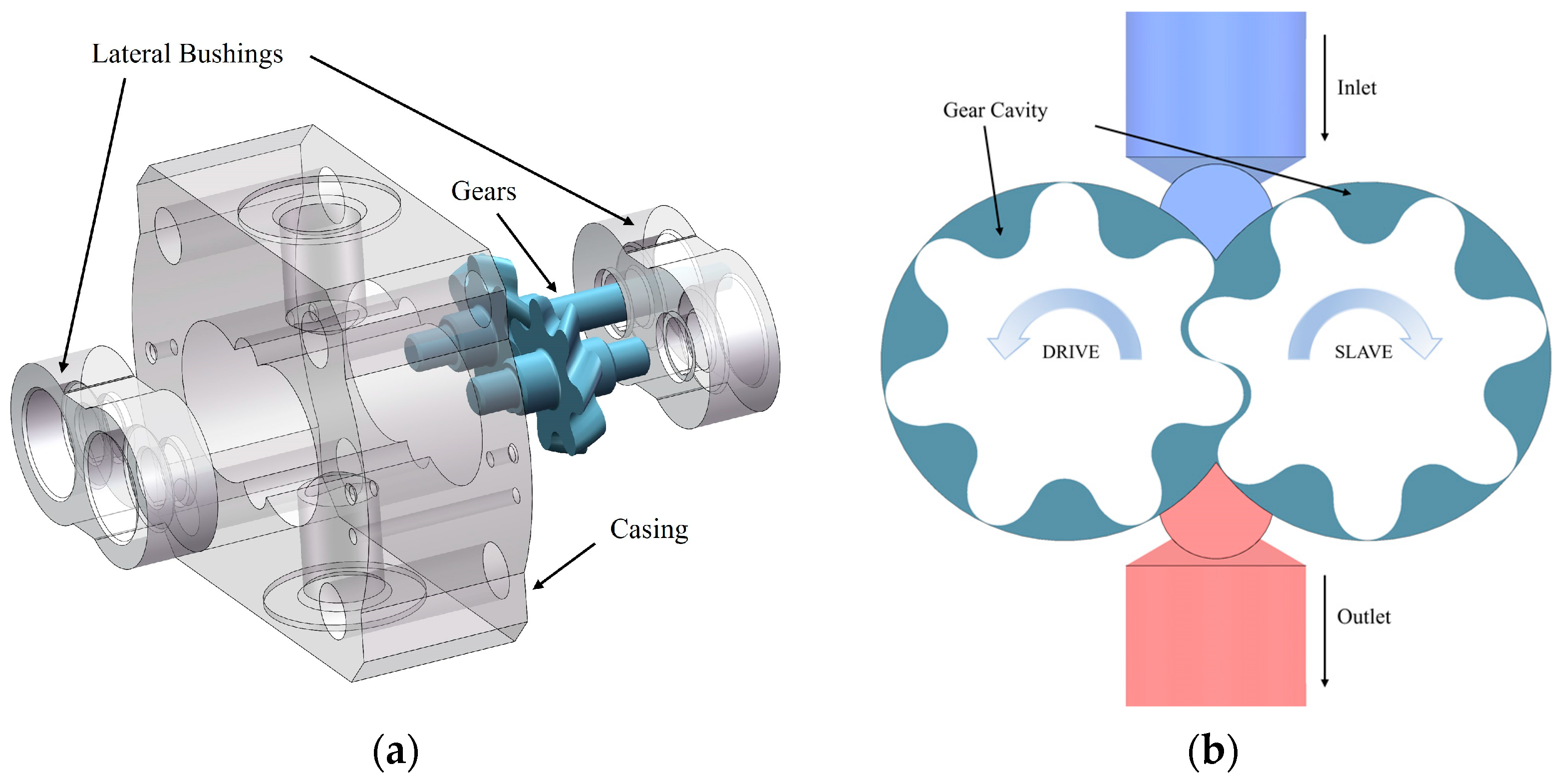
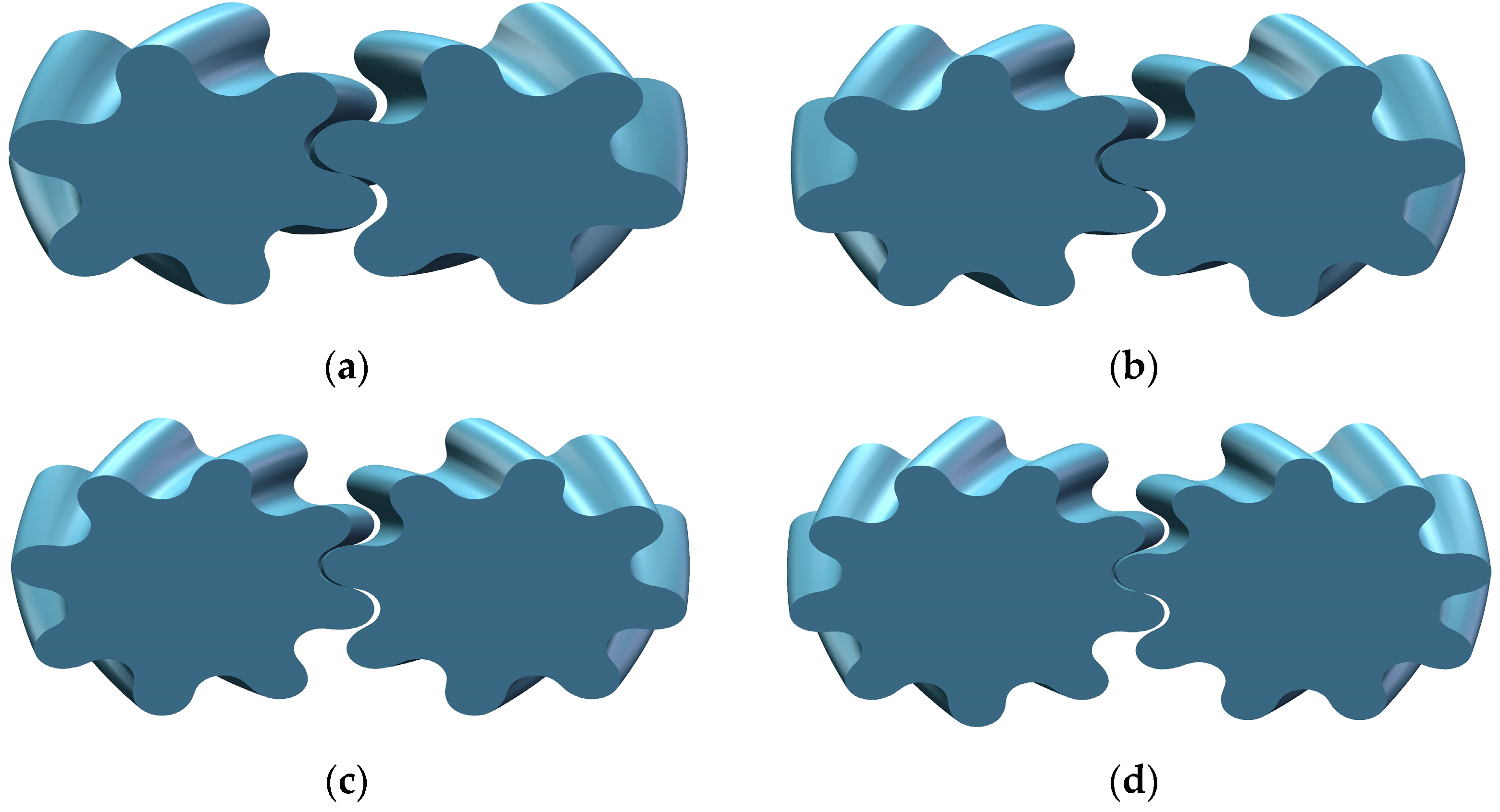
2.1. Design of Gear Pump Structural Parameters

The parameters of the circular arc spiral gear pump model are inlet pressure 0.1 MPa, outlet pressure 5 MPa while the pressure angle of the gear is taken to be 14.5°, which helps to reduce the pressure pulsation and the radial force on the gears [24]. For this purpose, the mathematical model of a six- to nine-teeth arc gear pump is created, and the effect of the tooth number on cavitation characteristics under different working conditions is assessed (set the speed as 7000–11,000 RPM).
According to the gear pump parameters in Table 1, Creo 10.0.0.0 software is used to create the physical model of the gear pump, and Figure 1a shows the structure of a gear pump group, which mainly includes the main wheel, the driven wheel, the case, and the lateral bushings.
Smooth arcs are used at the root and top of the teeth on the face profile of the gear, and the intermediate transitions of the teeth are connected by sinusoidal curves. During the operation of circular arc spiral gears, the contact point on any cross-section is only a single point, i.e., the degree of end-face overlap is lower than 1, which is not conducive to a smooth gear pump operation. To improve the axial overlap and ensure that the gear continues to rotate, the spiral design is introduced. This design enhances the contact between the gears and thus improves its working performance [25]. Therefore, the circular arc spiral gear pump is theoretically free from the phenomenon of trapped oil, which reduces the wear and the operating noise caused by the trapped oil. The schematic diagram of the gear pump operation principle is shown in Figure 1b.
As shown in Table 1, for the same outside diameter of gear with four different numbers of teeth, that is, De = 25.36 mm, other geometric parameters of the gears with six to nine teeth are as follows: the inlet and outlet diameters are 12.5 mm, and the clearance between the top of the housing is 40 µm while the tooth top clearance is 30 µm.
As shown in Figure 2, to maintain the axial overlap of one, the corresponding helix angle β reduces as the number of teeth increases. Under the premise of maintaining the same outer diameter size, the rise in the number of teeth results in an increase in the number of gear cavities, but reduces the gear pump’s working volume.

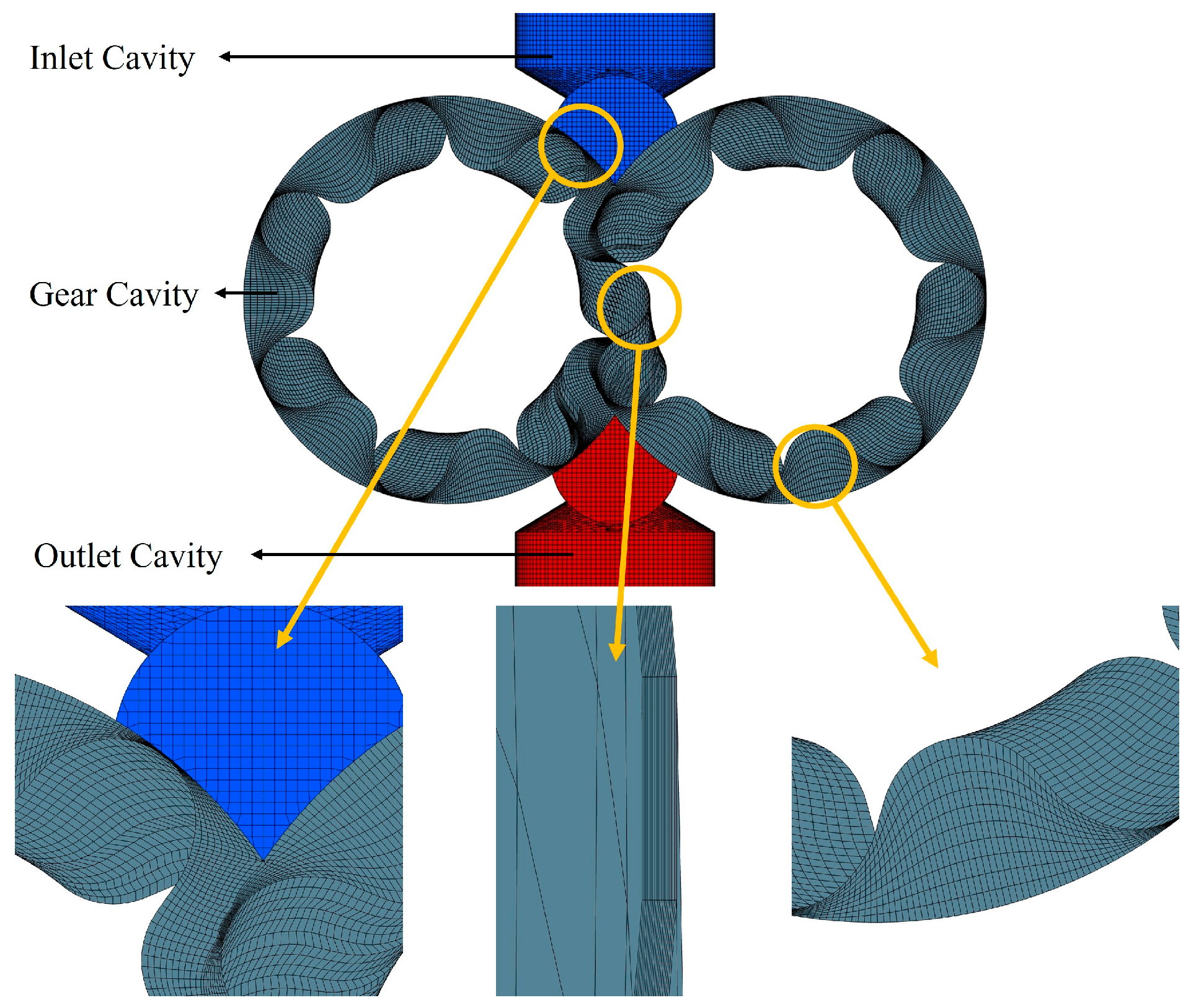
2.2. Mesh Division and Boundary Conditions

As shown in Figure 3, using the seven-teeth gear as an example, the internal flow field of a circular arc spiral gear pump can be extracted as follows, and Simerics MP+ version 6.0.0 software can be used for mesh division and numerical simulation. Pumplinx is a professional computational fluid dynamics software designed to simulate fluid flow in pumps and other fluid machinery and is widely used in industry for its robustness and accuracy in simulating complex fluid dynamics problems. The whole mesh area is divided into three main parts: the inlet cavity, gear cavity, and outlet cavity. In order to ensure the mesh quality while reducing the simulation error, a quadrilateral-structured mesh is used for the gear domain.
Set a standard atmospheric pressure for the suction inlet boundary condition of the circular arc spiral gear pump; the outlet pressure of the pressurized oil is 5 MPa, the speed is 7000–10,000 RPM, the gas mass fraction is 5 × 10⁻⁵, the density of the hydraulic oil of the conveying medium is 800 kg/m3, and the dynamic viscosity is 0.007 Pa   ·   s . The computational model selects the turbulence model and cavitation model, in which the turbulent flow model is set to a standard model. The default converge criterion is 0.1 for transient simulations; the rest of the settings are kept as default.
Pumplinx provides three formats for numerical solving, namely an upwind solving format, a central solving format, and a second-order upwind solving format. In this paper, the simulations are set up to select the second-order upwind for the velocity-based solution format and the upwind for the pressure-based solution format. Both the ‘turbulent kinetic energy’ and the ‘turbulent energy dissipation rate’ are set as upwind.
The gear pump rotates five cycles in total, in which the time step of rotation of each tooth is 30, and each step corresponds to a rotation of 1.714°; then, 210 steps are rotated per circle. The mesh motion is handled using a dynamic mesh approach to accurately capture the transient cavitation effects during gear meshing. Compare the outlet flow at the corresponding time step in two adjacent cycles to ensure the periodic stability of the simulation results. When the relative difference is less than 5%, the simulation is considered to achieve the stability requirement, and the resulting stable state is used for analysis.

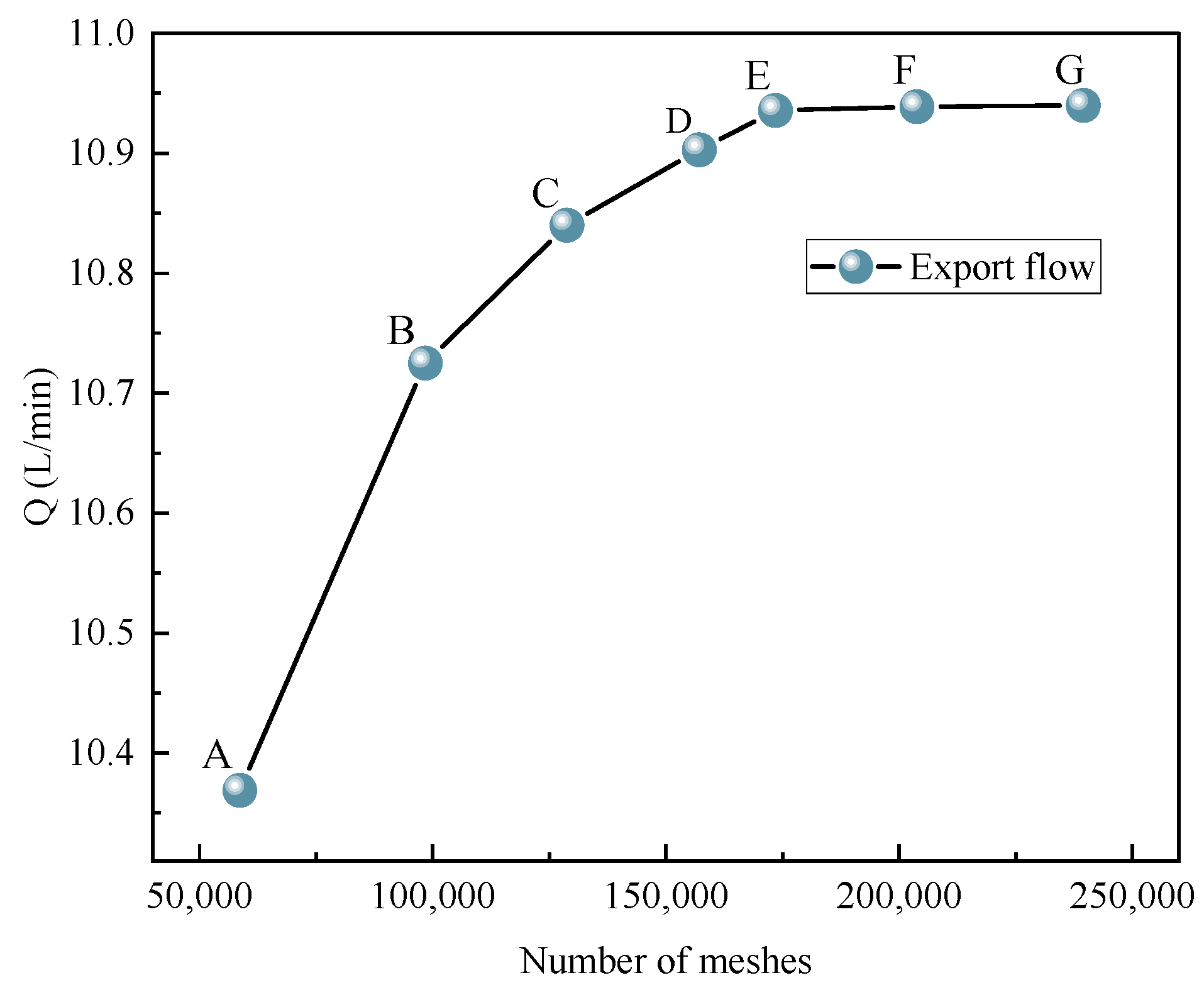
2.3. Mesh Independence Verification

Considering the cavitation model’s high demands on the mesh number and quality, taking the seven-teeth gear pump as an example, six computational models with different numbers of meshes are generated by adjusting the mesh division scale.
Figure 4 shows the effect of different mesh numbers on the outlet flow Q. The calculation results fluctuate greatly when the number of cells is less than 1.73 × 10⁵ (E point). Compared with point E, the average outlet flow calculation error of points A, B, C, and D is 5.18%, 1.92%, 0.87%, and 0.3%, respectively. As the number of cells gradually increases from point E to point G, the calculation results of the outlet flow are relatively stable. Compared with point E, the average outlet flow calculation errors of point F and point G are 0.029% and 0.04%, respectively.
For calculation accuracy and reduction in computer resource consumption, it is determined that the optimal number of cells for the seven-teeth gear pump calculation model is 1.73 × 10⁵. As shown in Figure 3, this model is divided into 480 circumferential mesh layers, 15 axial mesh layers, 10 radial mesh layers, and 20 inter-tooth clearance mesh layers. Using a similar meshing strategy, we obtain the meshing numbers of the six-teeth, eight-teeth, and nine-teeth gear pump models, which are 1.72 × 10⁵, 1.74 × 10⁵, and 1.94 × 10⁵, respectively.

2.4. Turbulence Model and Cavitation Model

Assuming that the hydraulic oil is an incompressible and continuous medium, the hydraulic oil in the gear pump is subjected to the high-speed rotary motion of the gears, and the flow characteristics are complex, so the oil flow is regarded as turbulent while the k-ε turbulence model is chosen here to describe the turbulent state. k-ε model is a two-equation model, which describes the turbulence effect by introducing the turbulent kinetic energy k and turbulent dissipation rate ε; it is one of the most widely used turbulence models because of its robustness, economy, and reasonable prediction of large-scale turbulence it is also often used in the calculation of the cavitation flow [26], whose equation is:
t ( ρ k ) + x j ( ρ u j k ) = x j ( μ + μ t σ k ) k x j + A A = G k + G b ρ ε Y m t ( ρ ε ) + x j ( ρ u j ε ) = x j ( μ + μ t σ ε ) ε x j + B B = C 1 ε ε k ( G k + C 3 ε G b ) C 2 ε ρ ε 2 k
where G k is the turbulent kinetic energy generated by the mean velocity gradient, G b is the turbulent kinetic energy generated by the buoyancy force, and Y m is the effect of compressibility on the expansion of the turbulent pulsation.
μ t is the turbulent viscosity, which can be calculated as follows:
μ t = ρ C μ k 2 ε
k for the turbulent kinetic energy, ε for the flow energy dissipation rate, and the five empirical constants C 1 ε , C 2 ε , C μ , σ k , and σ ε   are 1.44, 1.92, 0.9, 1.0, and 1.3.
Cavitation is a phase change process; the pressure change of the flow field leads to the mutual transformation of gas and liquid phases; how to describe the mass transfer between the two phases becomes a key issue in the numerical simulation of cavitation [27]. The gas phase in the cavitation regions is assumed to behave as an ideal gas, which simplifies the calculations and is a reasonable approximation to the conditions studied. In the present paper, the cavitation model proposed by Singhal et al. [28,29] is adopted, which takes into account the effects of phase change, pressure variations, vacuole movement, and the change in density of the medium with gas content. Its basic expression is as follows:
t Ω ( t ) ρ f v d Ω + σ ρ v v σ n f v d σ = σ D f + u l σ f f v n d σ + Ω R e R c d Ω
where   ρ   represents the density of the gas-bearing fluid, f v is the mass fraction of the vapor, v is the fluid velocity, v σ is the fluid surface velocity, D f is the vapor diffusion coefficient, u t is the turbulent viscosity, σ f is the turbulent Schmidt number, R e is the vapor generation rate, and R c is the gas phase condensation rate. The R-P equation is the description of the cavitation growth process under ideal conditions, and the model expression is as follows:
r d 2 r d t 2 + 3 2 d r d t 2 + 2 σ ρ l r + 4 μ l ρ l r d r d t = P v P ρ l
where r stands for the bubble radius, P stands for the liquid pressure, σ stands for the surface tension coefficient, ρ l stands for the oil fluid density, and P v stands for the saturated vapor pressure of oil. Because cavitation takes place at pressures below the saturated vapor pressure, it is assumed that the pressure in the interior of the bubble is equal to the saturated vapor pressure at room temperature. If we ignore the second derivative, surface tension, and viscosity terms, Equation (4) can be simplified as:
d r d t = 2 3 P v P ρ l
The steam generation rate and gas phase condensation rate can be obtained as follows:
R e = C e ρ l ρ v 2 p ρ v 3 ρ 1 1 / 2 1 f v f g , P P v R c = C c ρ l ρ v 2 p ρ v 3 ρ 1 1 / 2 f v , P > P v
Considering the effects of vapor and non-condensable gases in the oil, the mixture density of the fluid ρ can be calculated as follows:
1 ρ = f v ρ v + f g ρ g + 1 f v f g ρ l
where ρ v is the density of the steam, ρ g is the density of the air, and f g is the fraction of the mass of the air in the fluid.
The volume fraction of the cavitation gas is expressed as follows:
V g = V s V t × 100 %
where V g is the gas volume fraction, V s is the cavitating region volume, and V t is the volume of the gear pump cavity.

2.5. Gear Pump Outlet Flow and Volumetric Efficiency

The gear pump volumetric efficiency can be calculated as follows:
η v = Q a Q t Q t = V n
where η v is the volumetric efficiency, Q a is the actual average discharge rate of the pump, Q t is theoretical average pump outlet flow, V is the theoretical flow rate of the gear pump per revolution of the pump, and n is the gear pump speed.
Under ideal conditions, without considering the oil viscosity and leakage, the theoretical displacement of a single rotation of the gear pump is calculated by the swept area method.
V = B 2 π R a 2 4 z R 2 2 c o s π 2 z s i n π 2 z

3. Results and Discussion

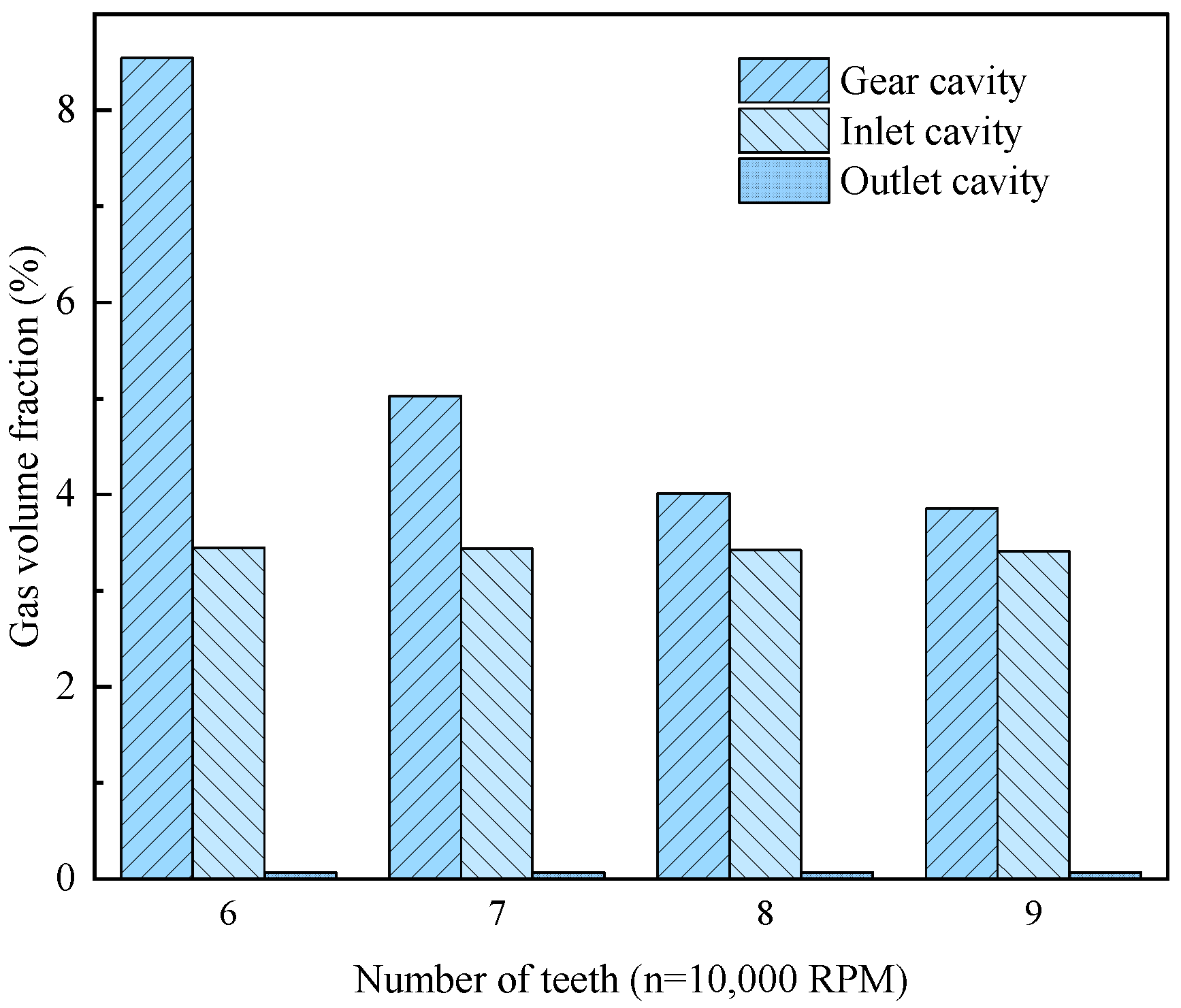
3.1. The Influence of the Number of Teeth on the Volume Fraction of Gas in Key Parts

The cavitation phenomenon in gear pumps most often occurs in the gear meshing area, near the unloading groove and the inlet and outlet area of the pump, where the gear meshing area is prone to bubbles due to severe pressure changes. Although the unloading groove reduces trapped oil, it may cause a pressure drop. The inlet and outlet areas, especially the inlet area, are prone to cavitation due to the increase in the flow rate and the decrease in the pressure. Leakage flow from side faces and radial clearances can also cause pressure drops. Relatively speaking, the phenomenon of trapped oil does not occur in the circular arc gear pump, so it is not necessary to consider the cavitation problem caused by the unloading tank [30,31].
As shown in Figure 5, the distribution of the gas volume fraction of the pump at a speed of 10,000 RPM exhibits an order from high to low: gear cavity region, inlet cavity, and outlet cavity. The area of cavitation severity is mainly in the meshing gap and meshing area. The gas content in the gear cavity region decreases significantly with the increase in the number of gear teeth, and the volume fraction of gas in the gear cavity decreases by 54.89% for tooth number nine compared to tooth number six. Compared to the inlet and outlet cavities in the different tooth numbers, the gas content is roughly the same, with an average value of about 3.42% and 0.69%, respectively, and a very small difference. The total gas volume fraction inside gear pumps with six and nine teeth is 12.06% and 7.33%, respectively, and the total gas content inside the pump with tooth number nine is reduced by 39.22% compared to that with tooth number six.
Because the gas content of the gear pump into and out of the mouth is less affected by the number of teeth, the focus of the discussion is the volume fraction of gas in the gear cavity.

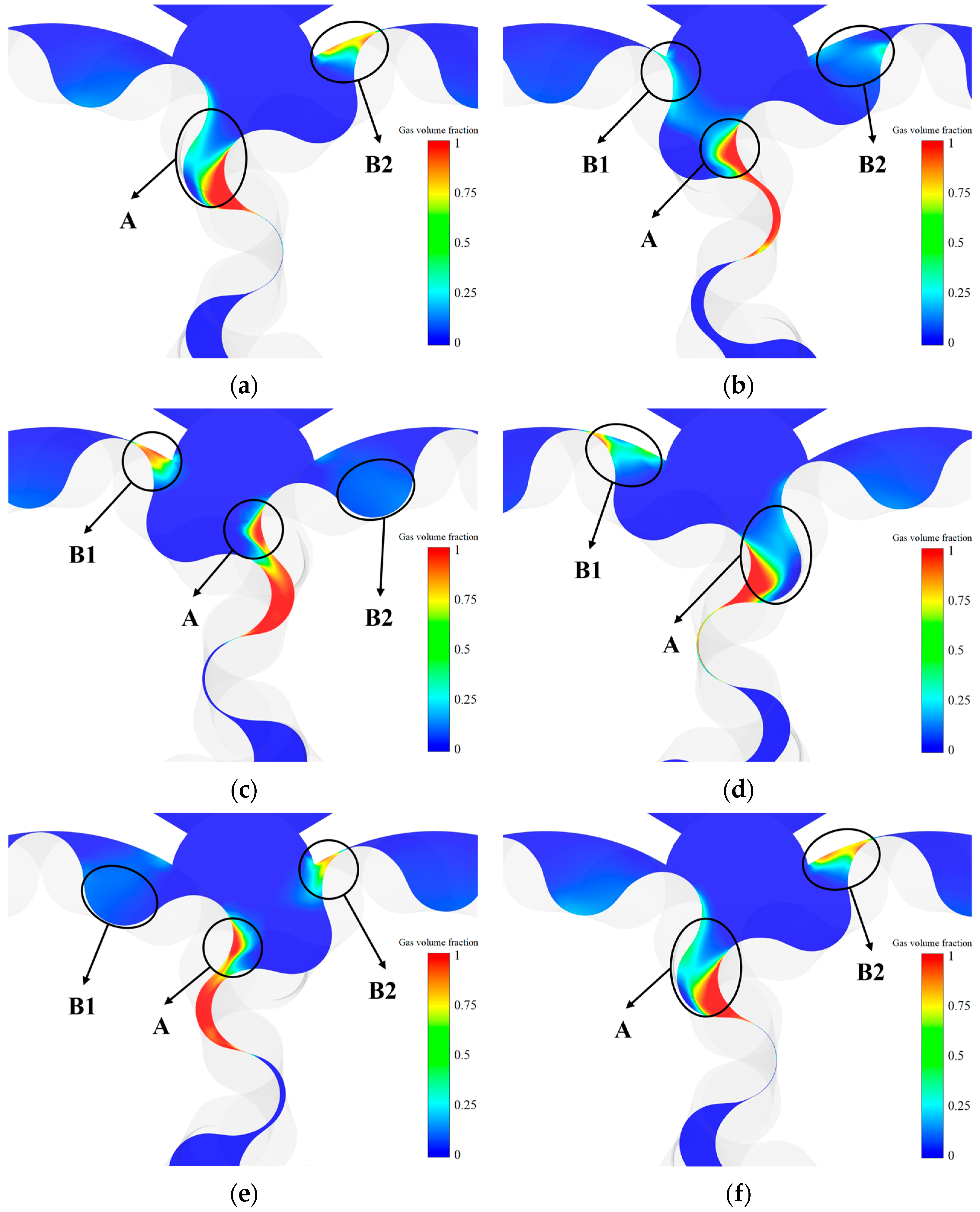
3.2. Cavitation Evolution Process of Gear Cavity

Take a seven-teeth gear pump as an example; analyze the cavitation process of a gear meshing rotation of 51.43° (a full cycle of rotation requires a turn of 360°, which is 0.006 s, i.e., 1.667 × 10⁻⁵ s per degree, and with a number of teeth of seven, while the gear rotation of a pair of gears involved in the angle of 51.43° and 8.57 × 10⁻⁴ s of time, the study focuses on the cavitation of a pair of engaging gear teeth during this process). The cavitation and evolution process of a seven-teeth gear pump can be obtained by numerical simulation. Figure 6 shows the cavitation cloud image of the middle section under different rotation angles. Six consecutive results are taken, with a 10.29° interval between each result. In Figure 6, A represents the location where cavitation occurs near the gear meshing point area, and B represents the location at which cavitation occurs between the rotor and the pump body.
Figure 6 clearly shows the cavitation gas distribution in the pump’s internal flow field at an initial 0°. The gas is mainly concentrated near the gear meshing point, while it is less distributed in the B1 and B2 regions far from the meshing zone. As the gears rotate, the cavitation phenomenon experiences a complete cycle of formation, evolution, and final disappearance during the process from 0° to 51.43°. Meanwhile, the cavitation cloud image at 0° and 51.43° showed a high consistency. During the gear pump operation, each time the tooth profile of one gear rotates to the corresponding location of the adjacent tooth profile on another gear, the cavitation phenomenon generated at the location is consistent, indicating that this cavitation has periodic characteristics.
In the process from 0° to 30.86°, with the expansion of the space between the teeth, serious cavitation occurred between the two teeth and near the meshing area while the cavitation area reached its maximum at 20.57°. Meanwhile, the cavitation area on the back of the driven gear in region A decreases with the increase in the rotation angle. From 30.86° to 51.43°, the cavitation area on the back of the drive gear in region A also decreases with the increase in the rotation angle. The dynamic change and periodicity of cavitation in the gear pump are revealed by this process.
According to the analysis of region B1 in Figure 6a–f, the cavitation phenomenon of region B1 underwent a process of formation, evolution, and disappearance at the Figure 6b–e moment. At Figure 6c 20.57°, many cavitation bubbles are formed, and at Figure 6e 41.14°, bubbles gradually fall off and break into small bubbles.
According to the analysis of region B2 in Figure 6a–f, it can be seen that at the time of Figure 6e-a–b-c, the cavitation phenomenon of region B2 underwent a process of formation, evolution, and disappearance. Many cavitation bubbles are formed at Figure 6f 51.43°, and the bubbles gradually fall off and break into small bubbles at Figure 6c 50.57°.

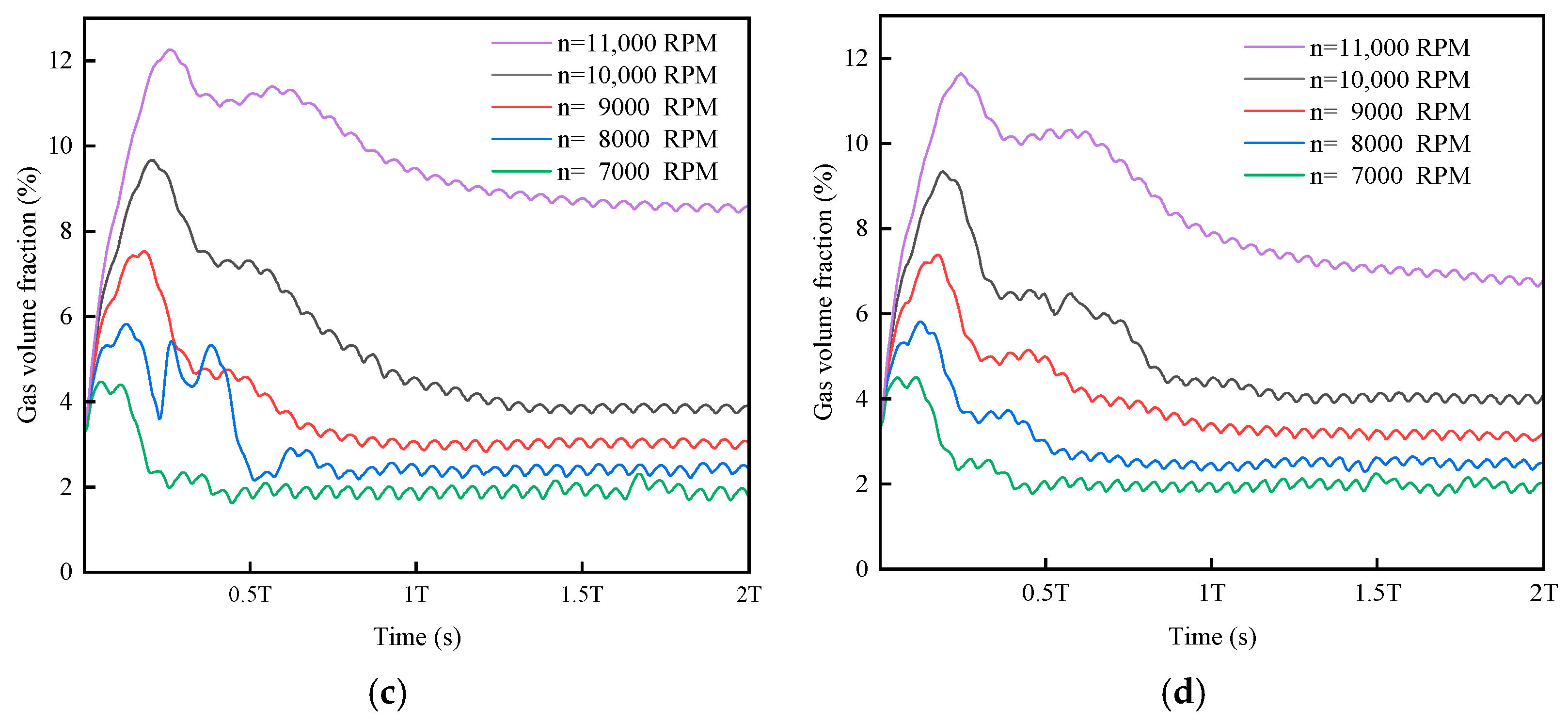
3.3. Influence of Speed on the Volume Fraction of Gas in the Gear Cavity

The gear pump with the number of teeth six and seven is set at a speed of 7000 to 10,000 RPM, while the number of teeth eight and nine is set at a speed of 7000 to 11,000 RPM. The effect of speed on the volume fraction of gas in the gear cavity was analyzed.
The significant effect of speed on the gas volume fraction in the gear cavity while keeping the gear outer diameter the same can be seen in Figure 7. As the speed increases, the peak gas volume fraction values for different numbers of teeth show an increasing trend. Taking 10,000 RPM as an example, the peak gas volume fraction of the six-teeth pump is the highest, reaching 11.51%. The peak values of seven-teeth, eight-teeth, and nine-teeth pumps are 10.35%, 9.67%, and 9.31%, respectively. Under other speed conditions, a similar trend is also shown; that is, as the number of teeth increases, the peak gas volume fraction gradually reduces.
Comparing the curves in Figure 7, it can be seen that at 7000 RPM, the gas content in the pump of all six to nine teeth show erratic fluctuation curves. However, as the speed continues to increase after the gear pump runs steadily, the fluctuation of the gas volume fraction becomes more stable.
As is clear from the data in Table 2, when other gear parameters are kept unchanged, the number of teeth has relatively little influence on the cavitation phenomenon at 7000 RPM, 8000 RPM, and 9000 RPM, respectively, and the average values of the cavitation phenomenon for each number of teeth at different speeds are 1.9%, 2.46%, and 3.15%, respectively. Taking the six-teeth model as an example, the growth rate of the air content in the gear cavity shows a marked unevenness as the speed increases from 7000 RPM to 10,000 RPM, which is 31.4%, 33.5%, and 158% successively. The air content of the pump increases abruptly, especially as the speed increases from 9000 RPM to 10,000 RPM. This indicates that there is a critical speed under this working condition, and when the speed exceeds 9000 RPM, the gear cavity will experience a serious cavitation phenomenon. A similar trend is observed for models with other tooth numbers, with critical speeds of seven to nine teeth being 9000 RPM, 10,000 RPM, and 10,000 RPM, respectively.

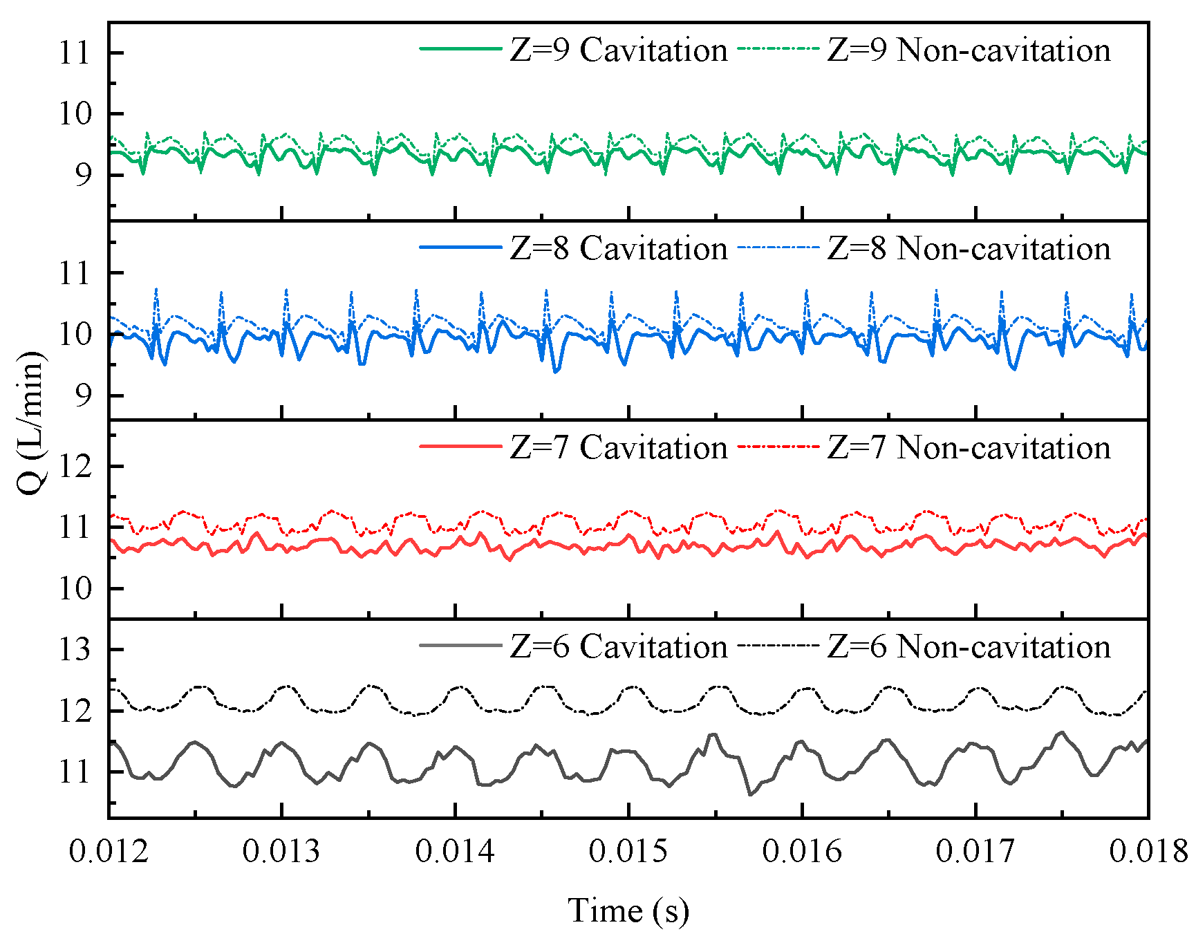
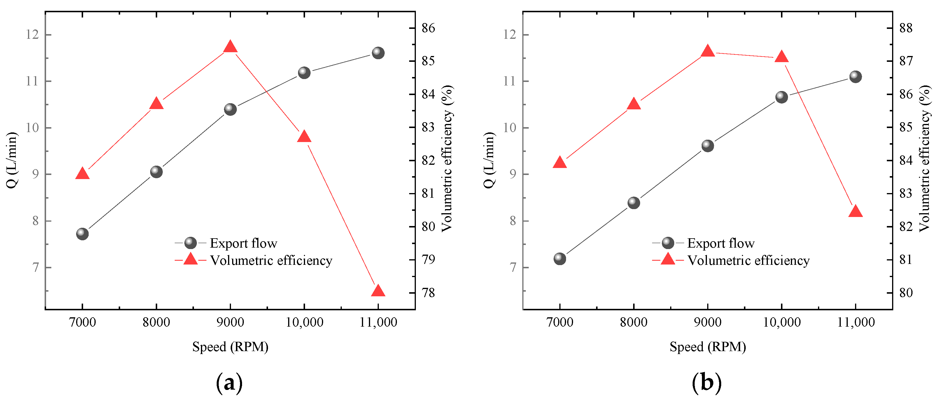
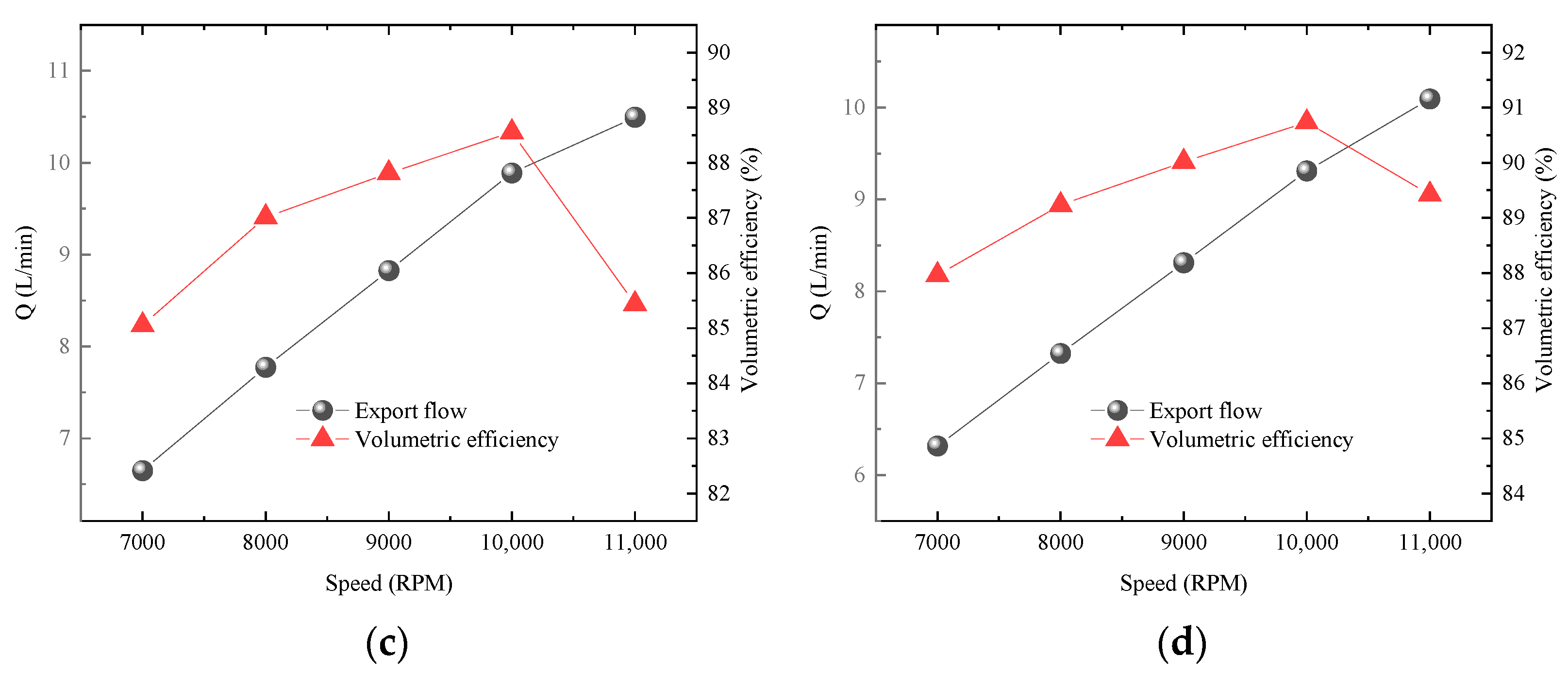
3.4. Influence of Cavitation on Flow Characteristics

A comparative analysis of four different numbers of teeth is conducted to analyze the influence of the number of teeth flow characteristics and performance under operating conditions with an inlet and outlet pressure difference of 5 MPa. These graphs, shown in Figure 8, depict in detail the influence of cavitation on the flow characteristics for gear pumps with six to nine teeth over a cycle.
Figure 8 shows the curves of the outlet flow Q under cavitated and non-cavitated conditions for gear pumps with six to nine teeth at a speed of 10,000 RPM. A curve of the gear pump after stable operation is selected for analysis, and the results show that the outlet flow presents obvious periodicity, while the influence of cavitation on the pump outlet flow varies significantly with the number of teeth.
Among them, the smallest reduction in flow due to cavitation is achieved with the nine-teeth gear pump, only 0.165 L/min, while the outlet flow of the six-teeth, seven-teeth, and eight-teeth gear pump is reduced by 0.992 L/min, 0.369 L/min, and 0.245 L/min, respectively. It can be seen that as the number of teeth increases, the output flow of the gear pump is affected by cavitation to a decreasing degree. The average outlet flow of six- to nine-teeth gear pumps is 11.18 L/min, 10.66 L/min, 9.89 L/min, and 9.31 L/min, respectively, and the volumetric efficiencies are 82.69%, 87.09%, 88.55%, and 90.73%.
Figure 9 shows the relationship between the outlet flows as well as the volumetric efficiency and speed for gear pumps with six to nine teeth, with each data point corresponding to the outlet flow and volumetric efficiency at that speed.
According to the flow calculation formula for external gear pumps, it can be concluded that there is a positive relationship between the pump outlet flow and speed under fixed displacement. This means that as the speed rises, so does the output. However, this linear relationship is not unlimited and fails once the speed exceeds a certain threshold. This is because too high a speed may result in the gear pump not being able to efficiently draw in the required oil and ensure that the tooth cavities are filled with oil, which can cause problems such as cavitation, vibration, and noise, as well as reduce the pump’s volumetric efficiency; this can impair the gear pump’s normal operation. Therefore, when the speed increases to the critical point where the volumetric efficiency begins to decrease, the gear pump is considered to have reached its critical speed.
From Figure 9, the gear pump outlet flow shows an increasing distribution with the increase in speed, while the volumetric efficiency shows an increasing and then decreasing trend with the speed. The speed is increased from 7000 RPM to 11,000 RPM; the export flow curve of the six-teeth gear pump changes most significantly; the slope of the flow curve slowly slows down, corresponding to the volumetric efficiency of 81.57%, 83.69%, 85.41%, 82.69%, and 78.02%, in order. At 9000 RPM, the volumetric efficiency reaches its highest value, then as the speed continues to increase, the volumetric efficiency starts to decrease, and the flow curve slope begins to slow down significantly. This situation is beyond the pump’s working capacity, which not only reduces the volumetric efficiency but may also cause damage to the normal operation of the gear pump and shorten its service life.
Gear pumps with other tooth numbers show similar trends: the seven-teeth gear pump’s volumetric efficiency peaks at 87.27% at 9000 RPM, while the eight- and nine-tooth gear pumps reach their highest volumetric efficiencies of 88.55% and 90.73% at 10,000 RPM, respectively. The conclusion is that as the number of teeth increases, so does the peak value of volumetric efficiency, and the critical speed corresponding to the peak volumetric efficiency also increases accordingly. This is due to the increase in the number of teeth, resulting in the gear volume ratio increasing, while the effective volume of the pump working is reduced, so that the theoretical displacement from six to nine teeth shows a downward trend, but this has a positive impact on the volumetric efficiency.
It can be seen from Figure 7, Figure 8 and Figure 9 that under the same conditions of inlet and outlet pressure difference, the gear pump speed increases within a certain range, and the volumetric efficiency and theoretical outlet flow per unit time are increased. However, once the speed reaches its respective critical values, the volume fraction of gas in the pump chamber will increase significantly, and the cavitation phenomenon will intensify, resulting in the volumetric efficiency beginning to decline. High speed will enhance the cavitation tendency of the fluid in the cavity, which will have an adverse influence on the output flow.

4. Conclusions

In this paper, the cavitation simulation of a circular arc spiral gear pump at high speed is carried out based on the CFD numerical method. The main research conclusions are the following:
Cavitation bubbles initially appear in the gap between the teeth. With the expansion in the volume of the meshing chamber, the bubbles gradually expand to near the gear meshing point area. At the end of the gear meshing, the bubbles begin to shrink and adhere to the gear surface, and then the large bubbles split into small bubbles, and finally separate from the gear surface.
Under the same outer diameter conditions of gears, as the number of teeth increases, the influence of cavitation on the outlet flow is significantly reduced. When the speed is 10,000 RPM, the volume efficiency of the seven- to nine-teeth gear pump is +5.32%, +7.09%, and +9.72% compared with that of the six-teeth gear pump.
When the speed of the pump exceeds its critical value, the gas content in the pump will increase sharply, resulting in serious cavitation, which will significantly shorten the service life of the pump. Therefore, in actual use, to making the pump speed exceed its critical speed should be avoided.
The number of teeth in a gear pump has a pronounced effect on the critical speed. When the number of teeth increases, the critical speed also increases. At an inlet and outlet pressure difference of 5 MPa, the limit speed of six-teeth and seven-teeth gear pumps is about 9000 RPM, and the critical speed of eight-teeth and nine-teeth is 10,000 RPM. When designing gear pumps, increasing the number of teeth is an effective strategy to help suppress cavitation, improve volumetric efficiency, and reduce flow pulsation.

Author Contributions

S.W.: Conceptualization, validation, formal analysis, writing—review and editing, project administration. H.W.: Investigation, formal analysis, writing—original draft, visualization. G.L.: Methodology, software, validation, funding acquisition. T.L.: Formal analysis, resources, data curation, supervision. All authors have read and agreed to the published version of the manuscript.

Funding

The research was supported by the Henan Province Science and Technology Research Project (Grant No. 242102220026) and Natural Science Foundation of Henan Province Project (Grant No. 252300420446).

Institutional Review Board Statement

Not applicable.

Informed Consent Statement

Not applicable.

Data Availability Statement

The detailed data are available upon request. The data are not publicly available due to privacy.

Conflicts of Interest

The authors declare no conflicts of interest.

Nomenclature

SymbolDescriptionUnit
ACenter distance[m]
BGear width[m]
RGear pitch circle radius[m]
R a Radius of toothed apex[m]
βHelix angle[°]
DeDiameter of tooth tip[m]
ZTooth number
nRotation speed[r/min]
G k ,   G b Turbulent kinetic energy[kg/(ms3)]
μ t Turbulent viscosity [ Pa   ·   s ]
C 1 ε ,   C 2 ε ,   C μ ,   σ k ,   σ ε Empirical constant
k Turbulent kinetic energy[m2/s2]
ε Flow energy dissipation rate[m2/s2]
f v Mass fraction of vapor
f g Mass fraction of air
v ,   v σ Fluid velocity, fluid surface velocity[m/s]
D f Vapor diffusion coefficient[m2/s]
σ f Turbulent Schmidt number
R e ,   R c Vapor generation rate, gas phase condensation rate
rBubble radius[m]
σ Surface tension coefficient
PPressure[MPa]
P v Saturated vapor pressure[Pa]
ρ ,   ρ v ,   ρ g ,   ρ l Density of gas-bearing fluid, density of steam, density of air, density of fluid in oil[kg/m3]
V g Gas volume fraction[m3]
V s Cavitating region volume[m3]
V t Volume of gear pump cavity[m3]
η v Volumetric efficiency[%]
Q a Actual average discharge rate of pump[L/min]
Q t Theoretical average pump outlet flow[L/min]
V Theoretical flow rate of gear pump per revolution of pump[m3]
TTime period for one complete rotation of gear pump[s]

References

  1. Ertürk, N.; Vernet, A.; Castilla, R.; Gamez-Montero, P.J.; Ferre, J.A. Experimental analysis of the flow dynamics in the suction chamber of an external gear pump. Int. J. Mech. Sci. 2011, 53, 135–144. [Google Scholar] [CrossRef]
  2. Gregory, W.P. External gear pumps for accurate and reliable metering duties. World Pumps 2006, 2006, 34–36. [Google Scholar] [CrossRef]
  3. Dearn, R. The fine art of gear pump selection and operation. World Pumps 2001, 2001, 38–40. [Google Scholar] [CrossRef]
  4. Antoniak, P.; Stryczek, J. Visualization study of the flow processes and phenomena in the external gear pump. Arch. Civ. Mech. Eng. 2018, 18, 1103–1115. [Google Scholar] [CrossRef]
  5. Stryczek, J.; Antoniak, P.; Jakhno, O.; Kostyuk, D.; Kryuchkov, A.; Belov, G.; Rodionov, L. Visualisation research of the flow processes in the outlet chamber–outlet bridge–inlet chamber zone of the gear pumps. Arch. Civ. Mech. Eng. 2015, 15, 95–108. [Google Scholar] [CrossRef]
  6. Chen, Y.; Xiong, D.F.; Li, Y.T.; Gao, Y.C.; Li, C.C.; Wang, B.Q.; Wang, J. Lubrication Characteristics of Gear End Face Friction Pairs of Aviation High-speed Gear Pumps. China Mech. Eng. 2024, 35, 1178–1187. [Google Scholar]
  7. Koukouvinis, P.; Naseri, H.; Gavaises, M. Performance of turbulence and cavitation models in prediction of incipient and developed cavitation. Int. J. Engine Res. 2017, 18, 333–350. [Google Scholar] [CrossRef]
  8. Lin, J.N.; Tseng, Y.T.; Chang, Y.Z.; Chou, Y.A.; Tsai, G.L.; Lan, T.S. Cavitation of Flow Field in Gear Pump. Sensor. Mater. 2022, 34, 2293. [Google Scholar] [CrossRef]
  9. Del Campo, D.; Castilla, R.; Raush, G.A.; Gamez Montero, P.J.; Codina, E. Numerical analysis of external gear pumps including cavitation. J. Fluids Eng. 2012, 134, 081105. [Google Scholar] [CrossRef]
  10. Del Campo, D.; Castilla, R.; Raush, G.A.; Gamez-Montero, P.J.; Codina, E. Pressure effects on the performance of external gear pumps under cavitation. J. Mech. Eng. Sci. 2014, 228, 2925–2937. [Google Scholar] [CrossRef]
  11. Concli, F.; Gorla, C. Numerical modeling of the power losses in geared transmissions: Windage, churning and cavitation simulations with a new integrated approach that drastically reduces the computational effort. Tribol. Int. 2016, 103, 58–68. [Google Scholar] [CrossRef]
  12. Ransegnola, T.; Zappaterra, F.; Vacca, A. A strongly coupled simulation model for external gear machines considering fluid-structure induced cavitation and mixed lubrication. Appl. Math. Model. 2022, 104, 721–749. [Google Scholar] [CrossRef]
  13. Liu, Y.Y.; Wang, L.Q.; Zhu, Z.C. Numerical study on flow characteristics of rotor pumps including cavitation. J. Mech. Eng. Sci. 2015, 229, 2626–2638. [Google Scholar] [CrossRef]
  14. Tao, R.; Xiao, R.F.; Wang, F.J.; Liu, W.C. Cavitation behavior study in the pump mode of a reversible pump-turbine. Renewable Energy 2018, 125, 655–667. [Google Scholar] [CrossRef]
  15. Yan, S.; Jiang, Y.; Hu, M.Y. Study on the cavitation suppression mechanism of axial piston pump. Int. J. Aerospace Eng. 2022, 1, 9913739. [Google Scholar] [CrossRef]
  16. Lian, J.; Wang, W.J.; Wang, X.Q.; Wang, X.C.; Zou, Y.Q.; Wu, G. Numerical simulation and experimental study on cavitation of micro high-speed fuel pump. Fluid Mach. 2024, 52, 58–66. [Google Scholar]
  17. Zhao, Z.J.; Fu, J.F.; Wei, S.J.; Wei, P.F.; Tong, L.; Jiang, Y. Analysis of the Influence Laws of Inlet Condition on the Volumetric Efficiency of the High-Speed Fuel Gear Pump. ICMAE 2022, 13, 184–189. [Google Scholar]
  18. Novakovic, B.; Radovanovic, L.; Zuber, N.; Radosav, D.; Dordevic, L.; Kavalic, M. Analysis of the influence of hydraulic fluid quality on external gear pump performance. Eksploat. Niezawodn. 2022, 24, 260–268. [Google Scholar] [CrossRef]
  19. Han, G.Z.; Huang, K.; Xiong, Y.S.; Kong, L.B.; Cang, D.J. Fluid analysis of the cavitation of the microsegment gear pump operating at high-pressure condition. J. Process Mech. Eng. 2023. [Google Scholar] [CrossRef]
  20. Ouyang, T.C.; Mo, X.Y.; Lu, Y.C.; Wang, J.X. CFD-vibration coupled model for predicting cavitation in gear transmissions. Int. J. Mech. Sci. 2022, 225, 107377. [Google Scholar] [CrossRef]
  21. Chao, Q.; Xu, Z.; Tao, J.F.; Liu, C.L.; Zhai, J. Cavitation in a high-speed aviation axial piston pump over a wide range of fluid temperatures. J. Power Energy 2022, 236, 727–737. [Google Scholar] [CrossRef]
  22. Yang, G.L.; Li, H.; Guo, J.X.; Zhang, Z.C.; He, H. Limiting Speed Characteristics of External Gear Pump Under the Influence of Suction Pressure. Chin. Hydraul. Pneum. 2021, 2, 91–94. [Google Scholar]
  23. Zhou, Y.; Hao, S.; Hao, M. Design and performance analysis of a circular-arc gear pump operating at high pressure and high speed. J. Mech. Eng. Sci. 2016, 230, 189–205. [Google Scholar] [CrossRef]
  24. Li, G.Q.; Zhang, L.F.; Han, W.F.; Deng, X.Z.; Feng, Y. Pulsation Characteristics Analysis and Tooth Profile Design of Double-circular-arc Helical Gear Pumps. China Mech. Eng. 2018, 29, 186–192. [Google Scholar]
  25. Castilla, R.; Gamez-Montero, P.J.; Campo, D.; Raush, G.; Garcia-Vilchez, M.; Codina, E. Three-Dimensional Numerical Simulation of an External Gear Pump With Decompression Slot and Meshing Contact Point. J. Fluids Eng. 2015, 137, 041105. [Google Scholar] [CrossRef]
  26. Wang, Y.; Huang, C.; Fang, X.; Yu, X.; Wu, X.; Du, T. Cloud cavitating flow over a submerged axisymmetric projectile and comparison between two-dimensional RANS and three-dimensional large-eddy simulation methods. J. Fluids Eng. 2016, 138, 061102. [Google Scholar] [CrossRef]
  27. Franc, J.-P.; Michel, J.-M. Fundamentals of Cavitation; Moreau, R., Ed.; Kluwer Academic Publishers: Dordrecht, The Netherlands, 2005; Volume 76, ISBN 1-4020-2232-8. [Google Scholar]
  28. Singhal, A.K.; Athavale, M.M.; Li, H.; Jiang, Y. Mathematical Basis and Validation of the Full Cavitation Model. J. Fluids Eng. 2002, 124, 617–624. [Google Scholar] [CrossRef]
  29. Yash, G.S.; Andrea, V.; Sadegh, D. Air Release and Cavitation Modeling with a Lumped Parameter Approach Based on the Rayleigh–Plesset Equation: The Case of an External Gear Pump. Energies 2018, 11, 3472. [Google Scholar] [CrossRef]
  30. Wu, B.; Ke, S.Y.; Wang, B.; Ye, Z.F. Study on Cavitation Performance of Three Gear Pump for Aircraft Engines. Mach. Build. Autom. 2022, 51, 61–64. [Google Scholar]
  31. Yang, J.L.; Lee, K.H.; Lee, C.H. Research on Cavitation Characteristics and Influencing Factors of Herringbone Gear Pump. CMES-Comp. Model. Eng. 2024, 139, 2917–2946. [Google Scholar] [CrossRef]
Figure 1. Schematic diagram of circular arc spiral gear pump. (a) Three-dimensional structural model of circular arc gear pumps; (b) Gear pump operating principle.
Applsci 15 03141 g001
Figure 2. Three-dimensional drawing of gears. (a) Z = 6; (b) Z = 7; (c) Z = 8; (d) Z = 9.
Applsci 15 03141 g002
Figure 3. A mesh model of the domain of the flow field domain of circular arc spiral gear pump. The mesh is divided into three parts, namely the inlet, gear, and outlet cavity.
Applsci 15 03141 g003
Figure 4. Impact of the number of cells on export flows.
Applsci 15 03141 g004
Figure 5. Gas volume fraction of each part of the gear pump with different numbers of teeth.
Applsci 15 03141 g005
Figure 6. Cavitation distribution in gears at different moments. (a) at moment 0°; (b) at moment 10.29°; (c) at moment 20.57°; (d) at moment 30.86°; (e) at moment 41.14°; (f) at moment 51.43°. Mark A for the location where cavitation occurs in the gear meshing point area; Mark B for the location where cavitation occurs between the gear and the pump body.
Applsci 15 03141 g006
Figure 7. Gas volume fraction curves corresponding to different speeds. The values of T for different gear speeds (7000–11,000 RPM) are 0.100857 s, 0.0075 s, 0.00667 s, 0.006 s, and 0.005454 s, respectively. (a) Z = 6; (b) Z = 7; (c) Z = 8; (d) Z = 9. (a,b) at 7000–10,000 rpm; (c,d) at 7000–11,000 rpm.
Applsci 15 03141 g007aApplsci 15 03141 g007b
Figure 8. Influence of cavitation on outlet flow.
Applsci 15 03141 g008
Figure 9. Relationship between outlet flow and volumetric efficiency and speed under different numbers of teeth. (a) Z = 6; (b) Z = 7; (c) Z = 8; (d) Z = 9. The left y-axis represents the export flow and the right y-axis represents the volumetric efficiency.
Applsci 15 03141 g009aApplsci 15 03141 g009b
Table 1. Geometric parameters of gears with 6–9 teeth.
Tooth Number6789
Center distance (mm)20.4821.0221.4621.828
Gear width (mm)4444
Helix angle (°)3025.71422.520
Table 2. Gas volume fraction table corresponding to different speeds.
Gas Volume Fraction7000 RPM8000 RPM9000 RPM10,000 RPM11,000 RPM
61.888%2.484%3.311%8.541%
71.886%2.443%3.117%5.036%
81.884%2.425%3.033%3.853%8.394%
91.935%2.485%3.123%4.014%6.665%
Average value1.898%2.459%3.146%
Disclaimer/Publisher’s Note: The statements, opinions and data contained in all publications are solely those of the individual author(s) and contributor(s) and not of MDPI and/or the editor(s). MDPI and/or the editor(s) disclaim responsibility for any injury to people or property resulting from any ideas, methods, instructions or products referred to in the content.

