Article

Risk Identification Method and Application of Roof Water Inrush Under Multi-Working Face Mining

1
College of Energy and Mining Engineering, Shandong University of Science and Technology, Qingdao 266590, China
2
College of Instrumentation & Electrical Engineering, Jilin University, Changchun 130022, China
3
School of Resources and Safety Engineering, Chongqing University, Chongqing 400044, China
*
Author to whom correspondence should be addressed.
Appl. Sci. 2025, 15(7), 3511; https://doi.org/10.3390/app15073511
Submission received: 13 February 2025 / Revised: 19 March 2025 / Accepted: 21 March 2025 / Published: 23 March 2025
(This article belongs to the Section Energy Science and Technology)

Abstract

:
Adjacent, multi-working face mining can expand the range of disturbed overburden, increasing the risk of triggering roof water inrush, which threatens the safe operation of coal mines. In this paper, we propose a risk identification method for roof water inrush under multi-working face mining conditions based on the theory of Key Strata and Full Mining Disturbance. Firstly, the key strata of the overburden are determined based on lithological and structural data from exploration boreholes. A formula is then derived to calculate the critical dimension (L) of the working face that could induce a fracture in the key stratum. The relationship between L and the combined width of the preceding and adjacent working faces is analyzed to assess whether the key stratum is fractured and how it affects the preceding working face. Finally, the height of the water-conducting fracture zone is predicted. The impact of repeated disturbances from multi-working face mining is evaluated to determine whether the height of the water-conducting fracture zone in the preceding working face increases, thereby enabling risk identification for roof water inrush under multi-working face mining conditions. Taking the multi-working faces of the Banji Coal Mine in Anhui Province as a case study, the predicted height of the water-conducting fracture zone is 60 m, with no risk of delayed roof water inrush in the preceding working face. Both numerical simulation results and field measurements of the development height of the water-conducting fracture zone confirm the effectiveness of this method. It is capable of accurately predicting the development height of the water-conducting fracture zone under multi-working face mining conditions and identifying the associated risk of roof water inrush, thus providing a valuable reference for ensuring safe mining operations in multi-working face mining conditions.

1. Introduction

After the extraction of coal seams, the original in situ stress field is disturbed, leading to significant movement of the overlying strata in the working face under the influence of mining activities. This movement results in the formation of fractures, which are known as water-conducting fracture zones [1,2,3]. These fractures can potentially connect the mined-out areas to roof water-bearing strata, creating artificial water-conducting pathways. Such pathways may increase the volume of water influx into the mine, cause the loss of groundwater resources, degrade the ecological environment of the mining area, and even trigger roof water inrush accidents, resulting in severe personnel and economic losses [4,5,6,7,8]. Zhang et al. [9] conducted a numerical simulation study on the spatiotemporal evolution of stress distribution during multi-working face mining. The results indicate that multi-working face mining leads to an expansion of the disturbed zone in the overlying strata, thereby increasing the likelihood of delayed roof water inrush accidents. Therefore, research on the risk identification of roof water inrush under multi-working face mining conditions is crucial for ensuring the safe operation of coal mines.
The key to the risk identification of roof water inrush lies in predicting the development height of the water-conducting fracture zone. Extensive research has been conducted by Chinese mining scholars on this topic. Zhang et al. [10,11] derived an empirical formula for the development height of the water-conducting fracture zone using statistical methods and theoretical analysis based on the equivalent permeability coefficient and groundwater hydraulic response. Zheng et al. [12] employed numerical simulation techniques to investigate the distribution of the stress field, displacement field, and plastic zone in the overlying strata and inferred the development height of the water-conducting fracture zone by integrating results from similar material simulation experiments and digital speckle experiments. Xu et al. [13] utilized fractal theory to study the evolution of overlying strata fractures and the development patterns of the water-conducting fracture zone during the advancement of the working face. They proposed a fracture location identification model for the overlying strata based on plate tectonics theory. In pursuit of more accurate predictions of the water-conducting fracture zone, Wu et al. [14] constructed a prediction dataset consisting of 122 fractured zones and developed prediction models using five machine learning algorithms, including linear regression. Chang et al. [15] focused on the working face under composite aquifers and employed methods such as staged upward drilling, water injection in boreholes, and numerical simulations to study the development height, morphological characteristics, and evolutionary processes of the water-conducting fracture zone during mining. Jing [16] and Xie et al. [17] investigated the use of distributed optical fiber monitoring to track the overlying strata deformation. They analyzed the correlation between changes in the optical fiber strain curves and the deformation, failure, and movement processes of the overlying strata in the mined area. Additionally, they explored the dynamic development process and mechanisms of the water-conducting fracture zone height and the fracture angles of the strata in the mined area. Issues related to measuring the heights of fracture and caving zones have been extensively studied by scientists worldwide, including in Europe, Australia, South America, and the United States [18,19,20,21,22]. Vlastos et al. [23] performed numerical simulations to analyze wave propagation in a medium characterized by a discrete distribution of fractures. The aim of their study was to investigate the dimensions and spatial distribution of fracture zones. Barlow et al. [24] conducted detailed analyses of the geometric characteristics of fracture zones and the stability of caving zones, utilizing advanced technologies such as laser scanning, groundwater seepage monitoring, and geological radar. Taucare et al. [25] employed topological methods to quantify the density of fracture zones within fault areas and explored their relationship with groundwater circulation.
While these studies provide valuable insights into the identification of water inrush risks, they have generally given limited consideration to the development patterns of water-conducting fracture zones and the identification of roof water inrush risks under conditions involving repeated disturbances from multi-working face mining. To address this gap, in the present study, we use the 110504 and 120501 working faces of the Banji Coal Mine as a case study and propose a method for identifying roof water inrush risks under multi-working face mining conditions. This method is based on the theory of Key Strata and Full Mining Disturbance, combining theoretical analysis, numerical simulations, and field data. This method effectively addresses the challenging issue of predicting the delayed development of water-conducting fracture zones during the continuous mining of multiple working faces. Integrating the key strata theory with the concept of full mining disturbance significantly improves both the accuracy and timeliness of assessing the risk of water inrush from the roof. The research findings hold significant practical implications for ensuring the safe operation of multi-working face mining [26,27].

2. The Theory of Key Strata and Full Mining Disturbance

Multi-working face mining can result in the expansion of the composite dimensions of the working face, which subsequently triggers the fracturing of the key strata within the overlying rock mass. This process increases the height of the water-conducting fracture zone, thereby elevating the risk of roof water inrush. When the height of the water-conducting fracture zone attains its maximum value under the prevailing geological conditions of the mining area, and no further increase in height occurs despite the continued expansion of the working face dimensions, this indicates that the failure of the overlying strata has reached a state of full mining disturbance. The working face dimension at which the failure of the overlying strata coincides with the maximum height of the water-conducting fracture zone is defined as the critical dimension of the working face [28].
Let the width of the preceding working face be denoted as L1, the width of the subsequent working face as L2, and the composite width of the multi-working face system as L3. The development of the water-conducting fracture zone and its relationship with the repeated disturbances induced by multi-working face mining are illustrated in Figure 1. The red line delineates the development extent of the water-conducting fracture zone following the extraction of working face L1, whereas the black line delineates the extent of the water-conducting fracture zone after the extraction of working face L2, indicating an increase in the height of the fracture zone.

2.1. Identification of Key Strata

In mining areas with multiple hard strata in the overburden, the strata that significantly influence the overall or partial movement of the rock mass are termed the key strata. When multiple strata undergo synchronous and coordinated deformation and failure, leading to surface subsidence, the lowest hard stratum is designated as the main key stratum. In contrast, if only a few strata within the rock mass experience coordinated deformation and failure without affecting the surface, the lower hard stratum is classified as a sub-key stratum. When the key strata fracture, the subsidence deformation of the overlying strata occurs in a coordinated and consistent manner [29,30].
The fracture of the key strata will result in the overall movement of all or a significant portion of the overlying strata. While multiple sub-key strata may exist within the overlying strata, there is only one main key stratum. Due to its superior strength, the main key stratum does not fracture concurrently with the sub-key strata. Fracturing of the main key stratum occurs only when its exposed area is sufficiently large enough to induce maximum stress that exceeds its strength limit. According to the key strata theory, when the main key stratum in the overburden fractures, a water-conducting fracture zone develops, extending to the top of the bedrock, with the height of this zone being equal to or greater than the thickness of the bedrock. Consequently, under similar geological conditions, the greater the distance of the main key stratum from the coal seam roof, the lower the risk of water inrush from the roof during mining operations [31,32].
The positions of the key strata are determined based on the load characteristics of the strata and their influence on the fracture sequence. This is achieved through a comprehensive stiffness and strength analysis of the strata [33,34].
The formula for identifying the position of the key strata based on stiffness is presented in Equation (1). In the identification process, calculations using E m + 1 h m + 1 2 i = 1 m h i γ i and γ m + 1 i = 1 m E i h i 3 are performed stratum by stratum, starting from the first stratum above the coal seam. When the m-th stratum satisfies Equation (1), the calculation process is terminated, and the (m + 1)-th stratum is designated as the first hard stratum. The position of the second hard stratum is then determined using the same method, and this procedure continues until the topmost hard stratum is identified. By identifying the positions of the hard strata, the locations of the overlying hard strata and the soft strata they influence are also determined.
E m + 1 h m + 1 2 i = 1 m h i γ i   >   γ m + 1 i = 1 m E i h i 3
In the equation, hi, γi, and Ei represent the thickness, unit weight, and elastic modulus of the i-th stratum (m, KN·m−3, GPa) (i = 1, 2, …, m, m + 1).
Strength identification primarily involves comparing the rupture distances of the hard strata to assess whether they will fracture simultaneously with the underlying key strata. Taking into account the influence of the stratum’s height relative to the coal seam and the fracture angle of the rock, the rupture distance for the j-th hard stratum is expressed using Equation (2).
S j = s j + 2 H j cot α
In the equation, sj represents the ultimate span of the j-th hard stratum (m); Hj denotes the distance from the j-th hard stratum to the upper surface of the coal seam (m); and α is the fracture angle of the stratum (°) (j = 1, 2, …, m, m + 1).
The ultimate span sj of the j-th hard stratum can be calculated using the following equation:
s j = h j 2 σ j q j
In the equation, σj represents the tensile strength of the j-th hard stratum (MPa); qj denotes the load borne by the j-th hard stratum (MPa).
The load qj borne by the j-th hard stratum can be determined using the following equation:
q j = E j h j 3 j = 1 m h j γ j j = 1 m E j h j 3
Evidently, the rupture distance of hard rock layers is of great significance in determining the critical layer position. To more intuitively demonstrate the influence of key rock-layer parameters on the rupture distance of a hard stratum, we studied the effects of the fracture angle and overburden stress on the rupture distance under the condition of determining the overburden structure. The overburden stress is characterized by the load transfer coefficient, and the larger the load transfer coefficient, the greater the load at the top interface of the bedrock. The relevant curves are illustrated in Figure 2 and Figure 3.
Our analysis reveals that as the rupture angle increases, the rupture distance of the hard rock layer decreases. Furthermore, the greater the overburden load, the smaller the rupture distance of the topmost fourth hard rock layer. Consequently, the position of the primary critical layer is influenced by the combined effect of the overburden stress and the loading from the upper layers. When the load is large or the rock layer rupture angle is large, there is a risk of overall rupture and structural instability of the overlying critical layers.
This finding highlights the significance of the rupture angle and overburden load as key parameters in determining the critical layer position. The inverse relationship between the rupture angle/overburden load and the rupture distance of the hard rock layers suggests that these factors need to be carefully considered when assessing the development and potential risks associated with the water-conducting fracture zone.

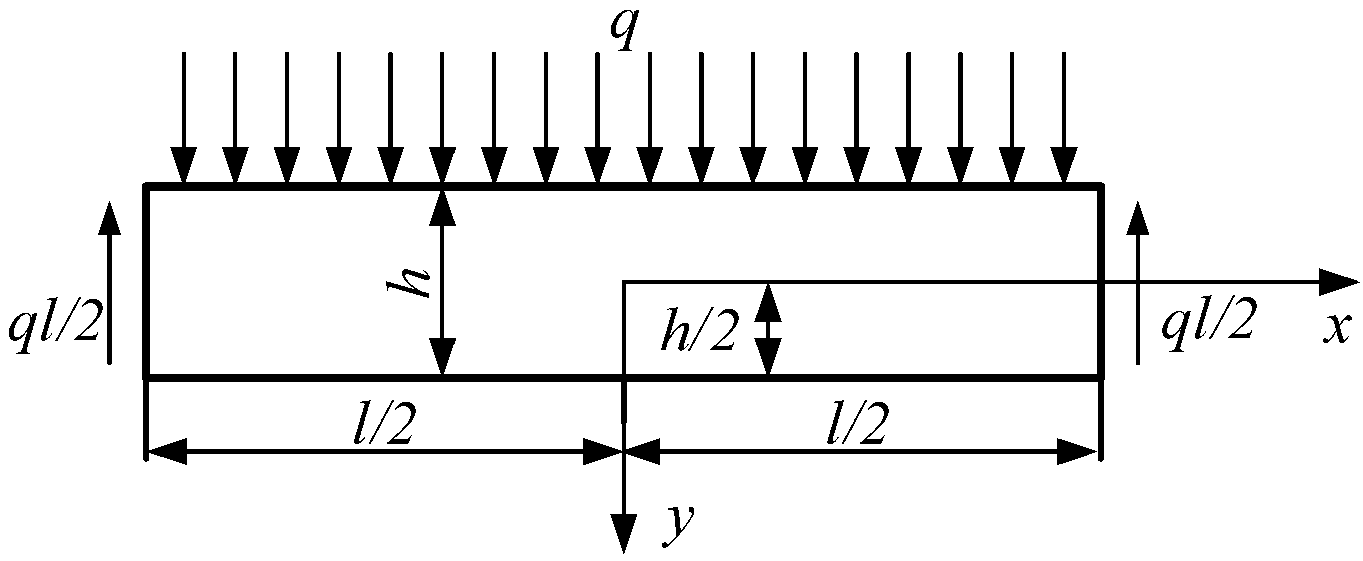
2.2. Critical Dimension Calculation

The void space created by mining in the working face is subsequently filled by the swelling characteristics of the roof strata. Swelling occurs only in the strata within the caving and fractured zones, while the strata in the bending and subsiding zones do not experience volumetric changes. When the swelling coefficient of the caving overburden approaches the residual swelling coefficient, the height of the water-conducting fracture zone reaches its maximum [28].
The void space Δk of the k-th key stratum is as follows:
k = M     i = 1 n h i ( K i   1 )
In the equation, M is the mining height (m); hi is the height of the i-th overlying stratum above the coal seam (m); Ki is the residual swelling coefficient of the i-th overlying stratum above the coal seam (i = 1, 2, …, n); and n is the overlying stratum number of the k-th key stratum.
The k-th key stratum prior to the initial fracture can be modeled as a simply supported beam. This beam experiences bending deformation under the combined effects of the overlying strata and its own weight. Utilizing the mechanical model of a simply supported beam subjected to a uniform load, as illustrated in Figure 4, the maximum deflection is calculated as follows:
ω max = 5 q k l k 4 384 E k I k max
In the equation, lk is the overhanging distance of the k-th key stratum (m); Ik is the moment of inertia of the cross-sectional area of the k-th key stratum with respect to the neutral axis (m4).
The fracture of the k-th key stratum in the overlying strata must simultaneously satisfy the following two conditions [35,36]: (1) The overhanging distance of the k-th key stratum must exceed its ultimate span at the time of initial fracture, implying that the dimensions of the working face must be sufficiently large. (2) The height of the free space below the k-th key stratum must be greater than the maximum deflection of the key stratum, as described by the following equation:
l k   >   s k 5 q k l k 4 384 E k I k   <   k
Therefore, when the thickness of the coal seam, as well as the lithology and structure of the overlying strata, are fixed, the ultimate span of the k-th key stratum must satisfy the following condition:
5 q k s k 4 384 E k I k   <   M     i = 1 n h i k i     1
Based on the above analysis, when the coal seam mining thickness and the lithology and structure of the overlying strata are fixed, for the k-th key stratum of rock, if its maximum span is sk, and the following condition is met,
5 q k s k 4 384 E k I k = M     i = 1 n h i k i     1
then the value of sk represents the critical span at which the overlying strata experience sufficient mining-induced disturbances. When the exposure distance lk of the k-th key stratum exceeds sk, the overlying strata are fully disturbed; when lk is less than sk, the overlying strata experience insufficient disturbance.
By solving Equations (2) and (9) simultaneously, the critical dimension of the working face for the fracture of the stratum is as follows:
L = 384 E k I k 5 q k M     i = 1 n h i k i     1 4 + 2 i = 1 n h i cot α
Clearly, the critical dimension of the working face for the fracture of the overlying strata is not only influenced by the intrinsic mechanical properties of the rock, but also closely related to the overburden load and the fragmentation characteristics of the underlying rock mass [37].

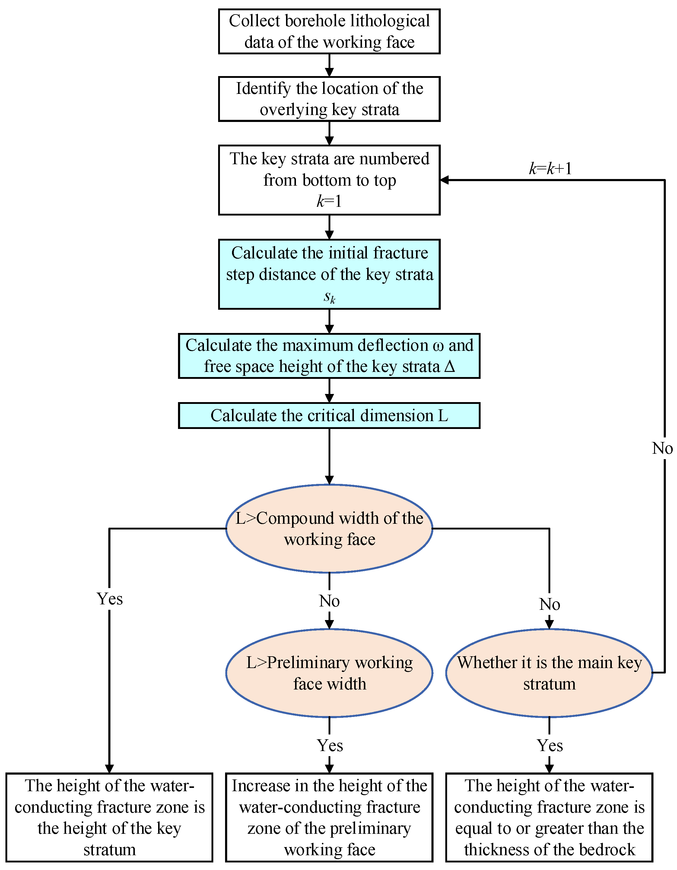
2.3. Prediction of the Development Height of Water-Conducting Fracture Zones

By integrating the identification of key strata with the calculation of critical dimensions, a predictive methodology for assessing the development height of water-conducting fracture zones influenced by multiple working faces is summarized, as illustrated in Figure 5.
  • When the critical dimension of the working face required for the fracture of the key stratum exceeds the combined width of the two working faces, the key stratum will remain intact, and the water-conducting fracture zone will not propagate upwards. Consequently, the maximum development height of the water-conducting fracture zone will be constrained to the height of the key stratum.
  • Conversely, when the critical dimension of the working face for the fracture of the key stratum is less than the combined width of the two working faces, the key stratum will fracture, allowing the water-conducting fracture zone to propagate upwards. In this scenario, the maximum development height of the water-conducting fracture zone will be limited to the height of the upper key stratum that has not yet fractured.
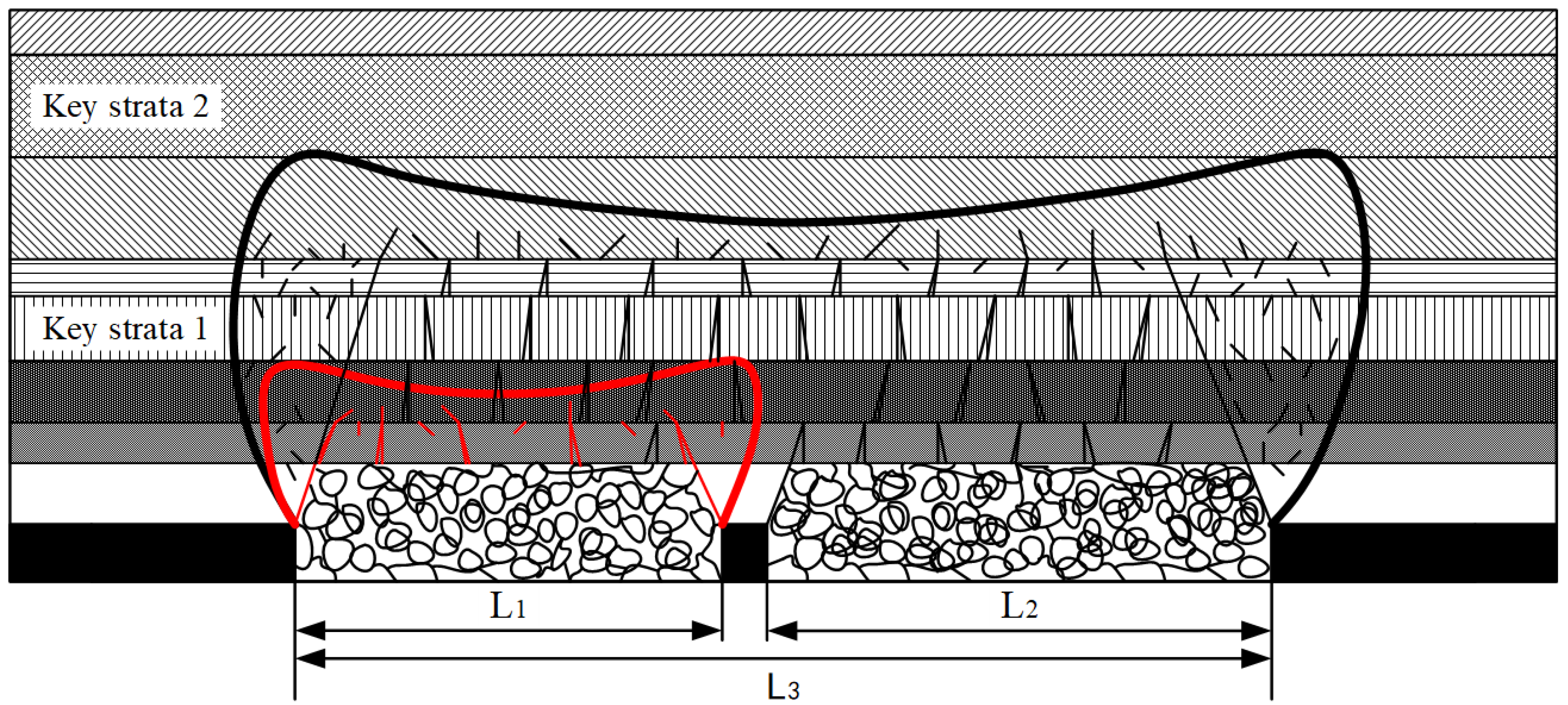
  • In cases where the critical dimension of the working face for the fracture of the key stratum is smaller than the combined width of the two working faces but greater than the width of the preceding working face, the mining-induced disturbance from the subsequent working face will result in an increase in the maximum development height of the water-conducting fracture zone in the preceding working face.
  • Finally, when the main key stratum fractures, the maximum development height of the water-conducting fracture zone will be equal to or greater than the thickness of the bedrock.
Figure 5. The process flow of the water-conducting fracture zone height prediction method.
Applsci 15 03511 g005

2.4. Identification of the Risk of Roof Water Inrush

Based on the theory of Key Strata and Full Mining Disturbance, in conjunction with the “Regulations on the Retention of Coal Pillars and Coal Mining near Buildings, Water Bodies, Railways, and Major Shafts”, the selection of the protective strata thickness must be made with careful consideration of several factors. These include the overall water content of the pore water-bearing strata in the newly formed loose strata, the development of underlying clay water-isolating strata, and the thickness of the oxidized zone. These factors should be evaluated separately for strong and medium water-bearing strata, strata without underlying water-isolating layers, and other water-bearing strata. The final determination of the protective strata thickness should be based on the properties of the medium-hard roof strata [38,39,40,41,42,43].

3. Engineering Application

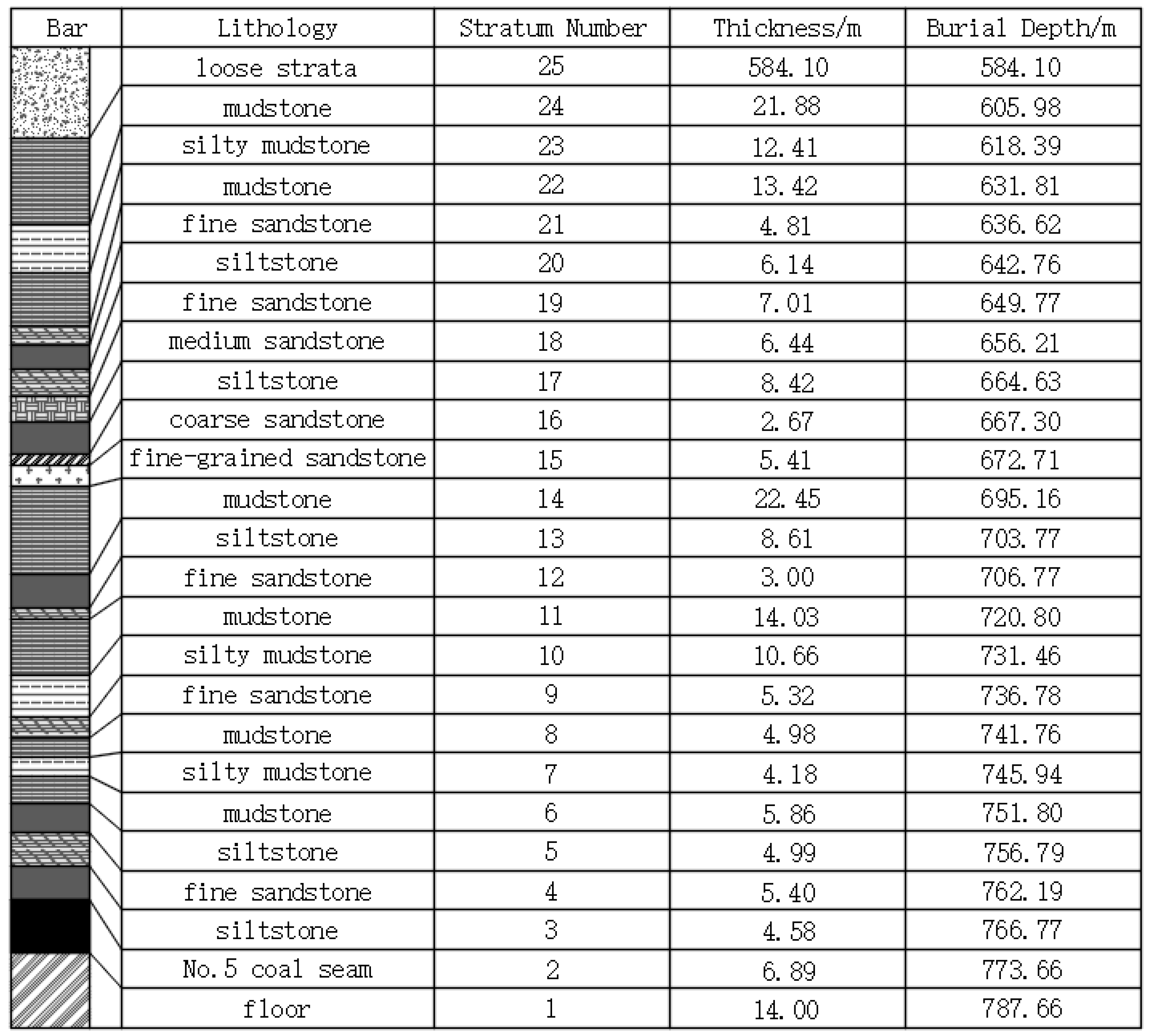
3.1. Engineering Overview

The Banji Coal Mine is located in Lixin County (116.2° E, 32.9° N), Bozhou City, Anhui Province, China, and primarily exploits the No. 5 coal seam. This seam has an average thickness of approximately 5.8 m, an average burial depth of about 770 m, and an average dip angle of approximately 8°. The 110504 and 120501 working faces are adjacent, with the 110504 face being the preceding face. The width of the 110504 working face is approximately 262 m, with a mining height of about 5.8 m. The 120501 working face has a width of about 270 m and a mining height of approximately 4 m. The combined mining width of both faces is 548 m, with a coal pillar width of 16 m (Figure 6; the coordinates are in the Beijing 2000 coordinate system).
The mining operations are influenced by the overlying water-bearing strata, which include the direct water-bearing strata, represented by the sandstone aquifer above the No. 9 coal seam, and the indirect water-bearing strata, which consist of the pore water-bearing strata in the newly formed loose strata. Under certain conditions related to the water-bearing strata and the structural characteristics of the overburden, mining disturbances may induce a risk of water inrush from the roof, posing a significant threat to the safety of coal seam extraction. The roof strata in the working face are primarily composed of medium-hard sandstone and mudstone. Based on exploration borehole data, the composite stratigraphic column of the working face is shown in Figure 7. The mechanical parameters employed in the numerical simulation model are estimated as follows: the compressive strength is 0.284 times the corresponding laboratory test value [44], while both the elastic modulus and tensile strength are 0.2 times the laboratory test values [45]. The physical and mechanical parameters of the composite strata at the working face are provided in Table 1.

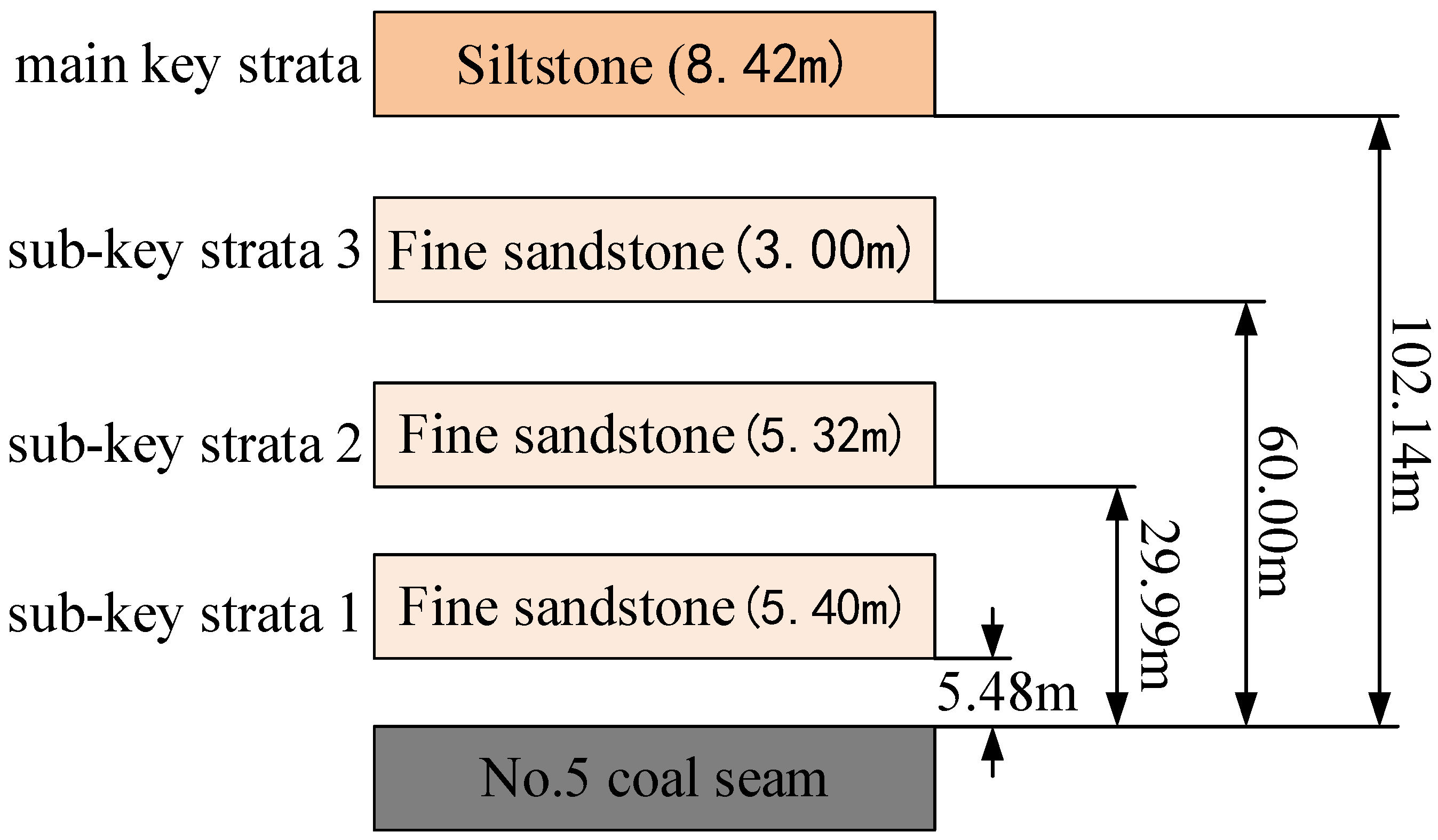
3.2. Engineering Theoretical Identification

The theoretical identification of the key strata position in the 120501 working face was performed using the key strata identification method, and the results are presented in Figure 8.
The theoretical calculation of the critical dimension for key strata failure in the 120501 working face was performed using the critical dimension calculation formula. The results of the calculations are presented in Table 2.
Based on the theory of Key Strata and Full Mining Disturbance, and with reference to the comprehensive physicomechanical parameters of the strata at the working face, it is predicted that when the mining height is 4 m, the maximum development height of the water-conducting fracture zone in the 120501 working face will reach 60 m. In contrast, the 110504 working face is not expected to face the risk of delayed water inrush from the roof.
The thickness of the protective strata should be no less than six times the thickness of the mined coal seam. Based on a mining height of 4 m, the protective strata thickness should not be less than 24 m.
The bedrock thickness of the 120501 working face ranges from 160 to 200 m. Given the predicted maximum height of the water-conducting fracture zone of 60 m, the protective strata thickness is estimated to range between 100 and 140 m. This exceeds the minimum requirement of 24 m, suggesting a low risk of water inrush from the roof.

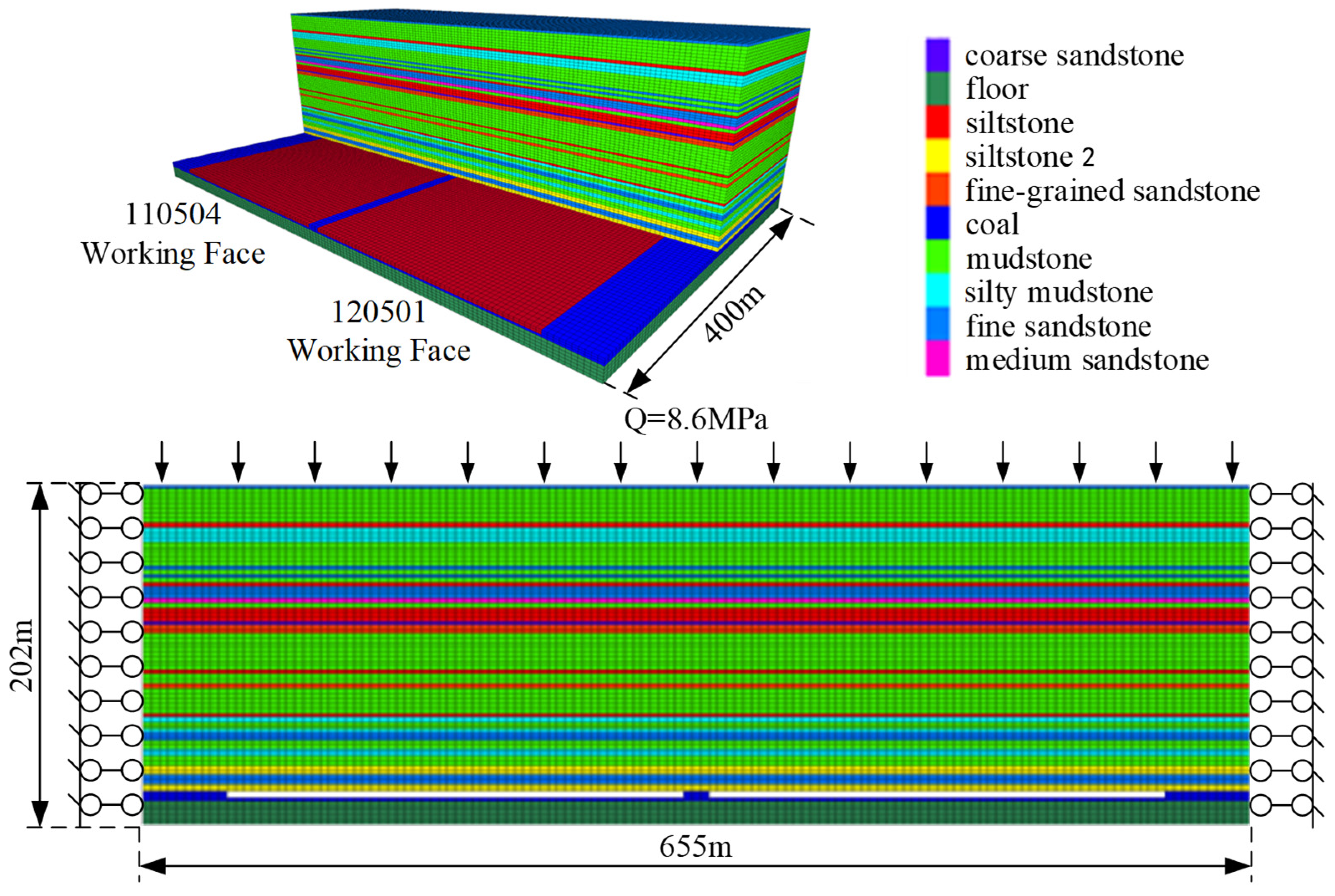
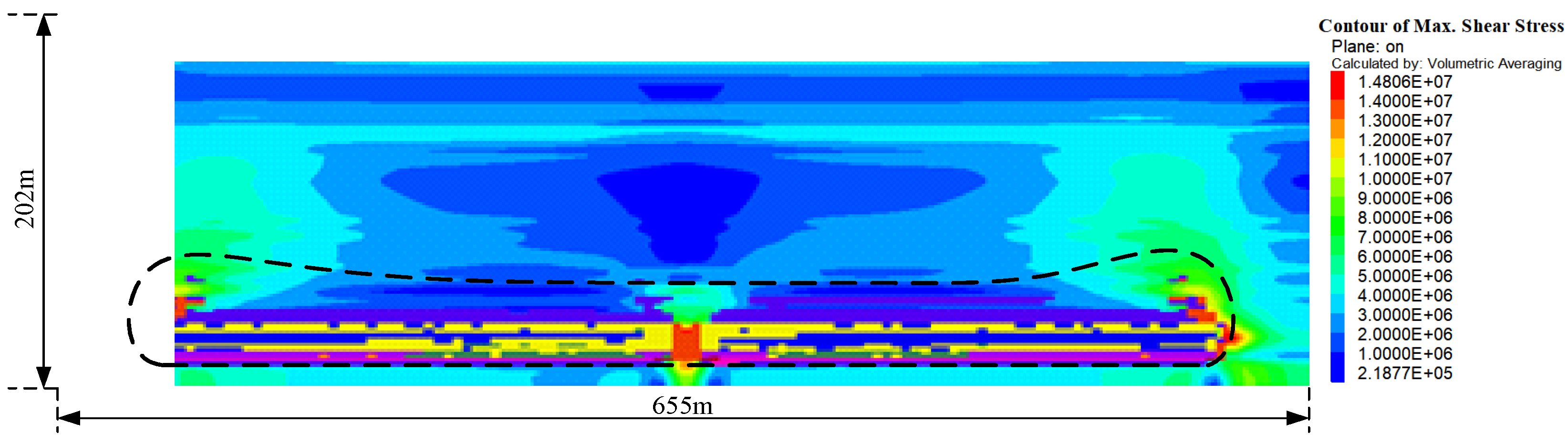
4. Numerical Simulation

FLAC3D is an internationally recognized software package for geotechnical engineering analysis, characterized by its powerful computational capabilities and extensive simulation features [46,47,48]. The maximum development height of the plastic zone can, to some extent, serve as an indicator of the development height of the water-conducting fracture zone in the overlying strata of the coal seam. Therefore, we employed FLAC3D 5.00 software to construct a model and conducted numerical simulations to validate the theoretical analysis by simulating the stress variations and plastic zone development during the coal seam excavation process.
A three-dimensional geological model composed of 35 strata was established by merging a small number of thin strata based on comprehensive geological data, as shown in Figure 9. The parameters were derived from internal laboratory testing reports. The model has a strike length of 400 m; two working faces are arranged in the dip direction, with a total length of 655 m and a grid spacing of 5 m. In the vertical direction, the model is divided according to different strata thicknesses, with unit thicknesses ranging from 3 to 5 m, totaling 202 m. The dimensions of the model are as follows: length (Y) × width (X) × height (Z) = 400 m × 655 m × 202 m. Horizontal constraints were applied to the model to reduce the influence of boundaries on the simulation results, with the bottom boundary fixed in velocity and the upper boundary free.
The presence of loose-confining, water-bearing strata significantly alters the mechanism by which the load from the overlying soil strata is transmitted to the interface at the top of the bedrock, compared to conditions where no water-bearing strata are present. In the case of loose-confining, water-bearing strata, the load from the overlying soil is uniformly transferred to the underlying bedrock through the water-bearing strata, facilitated by the mobility and replenishing effect of the confined water. During excavation, the load at the bedrock interface remains relatively constant. The loose-confining, water-bearing strata play a crucial role in the uniform transmission of this load. For instance, considering the overburden structure shown in Figure 7, with a loose strata thickness of 584.1 m and the pore water-bearing strata in the newly formed loose strata having a thickness of h = 65.88 m, the thickness of the overlying soil strata above the pore water-bearing strata in the newly formed loose strata is H = 518.22 m. The average unit weight of the soil is γ = 20 KN/m3, while the average unit weight of the water-bearing strata is γsat = 18 KN/m3. The total stress acting on the bottom boundary of the water-bearing strata is as follows:
σ = γ H + γ sat h = 11.55   Mpa
The pore pressure of the water-bearing strata is μ = 5.7 MPa.
The effective stress of the skeleton is
σ = σ u = 5.85   Mpa
The load acting on the bedrock interface is
P = u + 0.5 σ = 8.625   Mpa
Therefore, a gravitational load (Q) of 8.625 MPa is applied to the upper boundary based on the physical and mechanical properties of the comprehensive strata at the working face. The distance from the goaf to the top of the model is approximately 182 m. Equivalent horizontal stresses, considering the stress gradient, are applied in the front, back, left, and right directions, with a lateral pressure coefficient of 0.8. The intact coal-rock mass is modeled using the Mohr–Coulomb model, and the excavation step is set to 20 m. After the excavation of the 110504 working face is completed, the excavation of the 120501 working face continues.
Three displacement monitoring points were established above the center of the 110504 and 120501 working faces, positioned at heights of 50 m, 75 m, and 100 m above the coal seam roof. The monitoring points for the 110504 working face are designated as Points 1, 2, and 3, while those for the 120501 working face are designated as Points 4, 5, and 6. The vertical displacement monitoring results of the roof are illustrated in Figure 10, and the distribution of the plastic zone is presented in Figure 11 and Figure 12.
Based on the observations presented in Figure 10, the extraction process of the 110504 working face resulted in a systematic collapse and subsidence of the roof strata. In contrast, although the roof strata of the 120501 working face experienced some degree of disturbance, the extent of subsidence was relatively minor. Following the completion of extraction at the 110504 working face, the settlement data indicate that the overburden had essentially reached a state of stabilization. However, during the continued extraction of the 120501 working face, significant subsidence and deformation of the overburden were observed, while the overburden of the 110504 working face continued to experience considerable subsidence. These findings suggest that the extraction of the 110504 working face had not yet achieved a state of full mining disturbance.
As illustrated in Figure 11 and Figure 12, the water-conducting fracture zone exhibits an approximate ‘saddle shape,’ characterized by elevated regions on both sides and a slightly lower central section. Upon completion of mining in the 110504 working face, the maximum development height of the water-conducting fracture zone was observed to be approximately 60 m. Following the extraction of the 120501 working face, the overall change in the plastic zone of the overlying strata was minimal. In the dip direction of the working face, the extent of the plastic zone exhibited a slight increase; however, its maximum height remains less than that observed in the strike direction, where the plastic zone has remained essentially unchanged. This finding indicates that the development height of the water-conducting fracture zone has not undergone significant alteration. Concurrently, after the mining of the 120501 working face, the stress conditions within the newly formed loose strata and the protective strata of the pore water-bearing stratum have shown little to no change, suggesting that the repeated mining disturbances exert minimal influence on the pore water-bearing protective strata of the newly formed loose strata.

5. Field Monitoring Verification

Microseismic monitoring was used on the 120501 working face to assess the development height of the water-conducting fracture zone in the roof following the extraction of the No. 5 coal seam. The development height was determined based on the daily maximum values recorded by the microseismic monitoring system. From the official operation of the monitoring system on 2 December 2023 to the complete destruction of the measurement line on 30 May 2024, the effective monitoring period lasted approximately six months. Microseismic events with a magnitude of 0.2 or higher were considered in the analysis. The comprehensive analysis revealed that the maximum development height of the water-conducting fracture zone in the 120501 working face was 64 m, which aligns well with the predictions derived from this method, thereby validating the effectiveness of the proposed approach. The daily maximum development height of the roof microseismic events during the mining of the 120501 working face is illustrated in Figure 13. This figure specifically presents the maximum height of the hypocenters associated with these roof microseismic events.
Throughout the mining period, the 120501 working face did not experience any roof water inrush incidents. Despite the repeated disturbances caused by mining activities at the 120501 working face, the 110504 working face did not encounter any delayed roof water inrush incidents either, which is consistent with the findings of the numerical simulations.
The surface subsidence at different stages of the 110504 working face was analyzed using monitoring points, as illustrated in Figure 14 and Figure 15.
From the figures, it can be observed that as the 110504 working face continues to advance, the point of maximum surface subsidence progressively shifts towards the center of the working face, eventually stabilizing and forming a funnel-shaped subsidence profile. Following the extraction of the 120501 working face, a secondary subsidence event occurred in the 110504 working face. As shown in Figure 16, the overall pattern of this secondary subsidence remains relatively unchanged, with no abrupt or sudden sinking observed. Analysis of the roof height data for both working faces reveals that the roof height of the 120501 working face is lower than that of the 110504 working face, and no delayed water inrush phenomena were detected in the 110504 working face. This suggests that repeated mining activities did not lead to a significant increase in the roof height of either the 110504 or 120501 working faces. Given that the 120501 working face is adjacent to the 110504 working face and shares similar overlying rock strata, it can be inferred by analogy that the risk of water inrush induced by an abnormal increase in roof height due to repeated mining activities is minimal.

6. Discussion

  • Overview: The research conducted in the domain of water-conducting fracture zone development and water inrush risk within mining engineering has significantly enhanced our understanding of the interactions between mining activities and geological formations. Key contributions to this field include the development of empirical formulas and predictive models for assessing the height of water-conducting fracture zones, employing various methodologies such as statistical analysis, numerical simulations, and machine learning techniques. Noteworthy studies have demonstrated the correlation between mining operations, stress distribution, and the likelihood of delayed water inrush incidents. Furthermore, innovative monitoring techniques, including distributed optical fiber systems, have been employed to track deformation in the overlying strata, providing valuable insights into the dynamic processes associated with fracture zone development. In summary, the findings not only contribute to the theoretical framework of mining engineering, but also offer practical implications for enhancing safety and environmental sustainability in mining practices.
  • Novelty: This study introduces a novel risk identification method for roof water inrush under multi-working face mining conditions, grounded in the theory of Key Strata and Full Mining Disturbance. The proposed method incorporates the cumulative effects of repeated disturbances from multiple working faces and involves the derivation of a critical dimension formula for key strata failure. This formula is then applied to assess the delayed risk of water inrush from the roof of previously mined working faces. The predictive results obtained using this method provide a more accurate representation of the overall developmental characteristics of the water-conducting fracture zone.
  • Limitations: The method for identifying the risk of roof water inrush under multi-working face mining conditions, based on the Key Strata Theory and Full Mining Disturbance Theory, relies on certain idealized assumptions. However, the actual geological conditions encountered in coal mining are often more complex, exhibiting anisotropy in the strata and spatial variability in rock properties, which may affect the general applicability and accuracy of the critical dimension calculation formula. Moreover, the analysis combining the Key Strata Theory and the Full Mining Disturbance Theory does not fully account for some dynamic factors that arise during the mining process. For instance, variations in mining speed can influence stress distribution and fracture development in the roof; however, the impact of this factor on the risk assessment of roof water inrush is not comprehensively addressed in the theoretical framework of the study. Additionally, the accuracy of the microseismic event location is significantly influenced by geological conditions. The underground environment in mining areas is often characterized by complex geological structures, such as fracture zones, bedding variations, and ore body distributions, all of which may lead to irregular refraction, reflection, or attenuation of seismic waves during propagation, thereby affecting the precision of the monitoring data. Background noise interference during the monitoring process may also reduce the accuracy of event localization to some extent [49,50].
  • Outlook: Future work should focus on further considering the non-uniformity of geological structures and rock mechanical properties to refine the critical dimension calculation formula for the failure of the key strata. The introduction of probabilistic analysis methods could be beneficial in accounting for the variability and uncertainty of parameters such as rock properties, thus making the formula more representative of actual geological conditions. Moreover, comprehensive research into the mechanisms by which dynamic factors, such as mining speed, influence the risk of roof water inrush is warranted. These dynamic factors should be incorporated into existing theoretical models to enhance their predictive accuracy and applicability in real-world mining scenarios.

7. Conclusions

  • A method of risk identification for roof water inrush under multi-working face mining conditions, based on the theory of Key Strata and Full Mining Disturbance, has been proposed. This method comprehensively accounts for the effects of repeated disturbances from multiple working faces and involves the derivation of a critical dimension formula for the key strata at the working face. When the critical dimension of the working face of the key stratum exceeds the combined width of the two working faces, the maximum development height of the water-conducting fracture zone is determined to be equal to the height of the key stratum. In contrast, if this dimension is less than the combined width, the maximum development height of the water-conducting fracture zone corresponds to the height of the unfractured portion of the upper key stratum. Furthermore, if the critical dimension exceeds the width of the preceding working face but remains less than the combined width of the working faces, there exists a risk of delayed water inrush from the roof of the preceding working face. Additionally, when the main key stratum experiences fracturing, the maximum development height of the water-conducting fracture zone is either equal to or greater than the thickness of the bedrock.
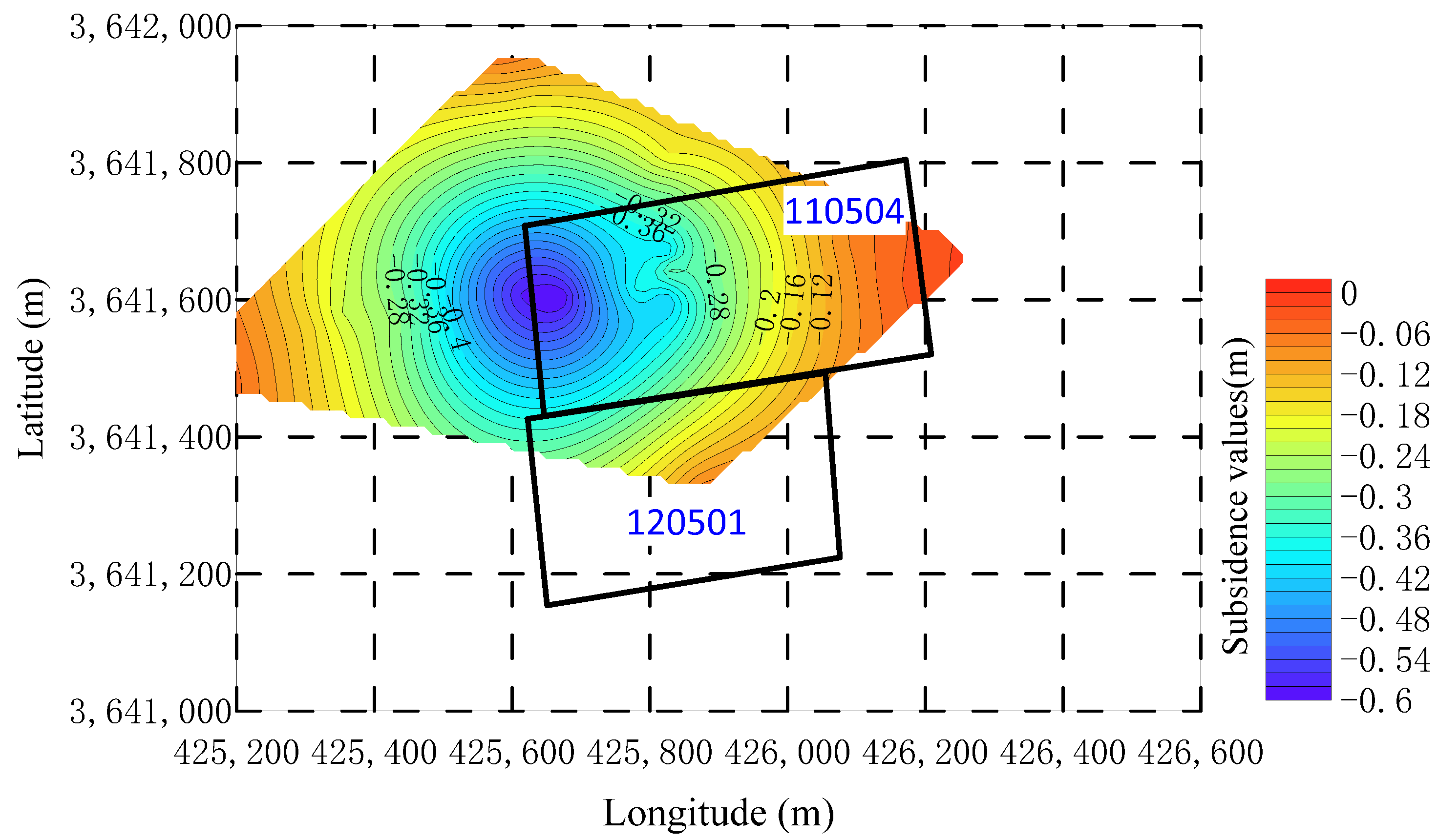
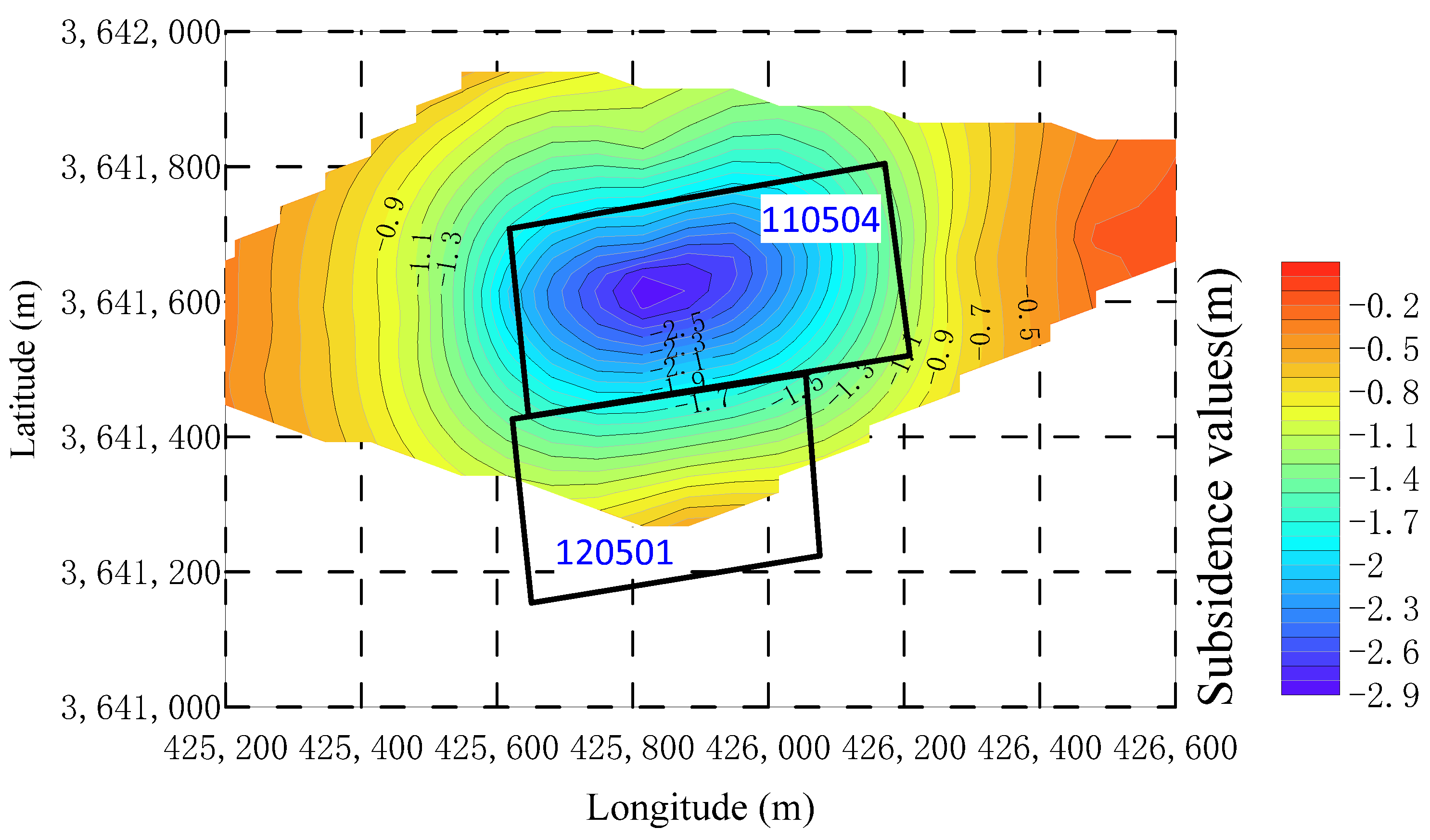
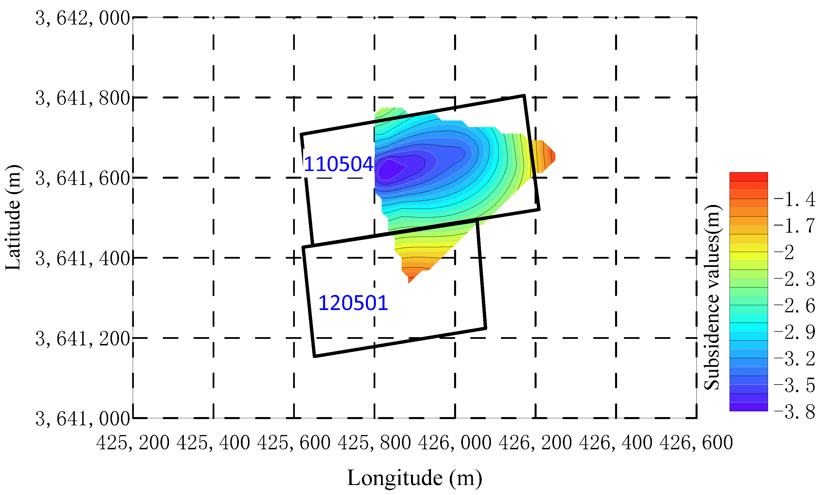
  • Based on the theory of Key Strata and Full Mining Disturbance, in conjunction with numerical simulation calculations, it was determined that, for a mining height of 4 m, the development height of the water-conducting fracture zone in the 120501 working face is approximately 60 m, with the protective strata thickness ranging from 100 to 140 m. Under these conditions, there is no risk of roof water inrush, and the adjacent 110504 working face is not at risk for delayed roof water inrush.
  • Microseismic monitoring was employed to measure the development height of the water-conducting fracture zone in the 120501 working face, which reached a maximum of 64 m. The development height of the water-conducting fracture zone in the 110504 working face remained unchanged, and no delayed roof water inrush was observed. The results align closely with the theoretical predictions, further validating the proposed method.

Author Contributions

Conceptualization, Z.H.; investigation, B.F. and Y.Z. (Yu Zhou); methodology, Z.H.; software, Y.Z. (Yongqiang Zhao) and X.L. (Xuebin Li); supervision, K.W. and X.L. (Xuesheng Liu); writing—original draft, Z.H.; writing—review and editing, K.W. and X.L. (Xuesheng Liu). All authors have read and agreed to the published version of the manuscript.

Funding

The research described in this paper was financially supported by the National Natural Science Foundation of China (No. 52204172, 52174122, and 52374218), the Excellent Youth Fund of Shandong Natural Science Foundation (No. ZR2022YQ49), and the Taishan Scholar Project in Shandong Province (No. tsqn202211150).

Institutional Review Board Statement

Not applicable.

Informed Consent Statement

Not applicable.

Data Availability Statement

The data used to support the findings of this study are available from the first author upon request.

Acknowledgments

The author would like to thank reviewers and editors for their kind work.

Conflicts of Interest

The authors declare no conflicts of interest.

References

  1. Gao, Y.F. “Four-zone” model of rockmass movement and back analysis of dynamic displacement. J. China Coal Soc. 1996, 21, 51–56. [Google Scholar] [CrossRef]
  2. Qi, T.Y.; Zhang, F.; Pei, X.M.; Feng, G.R.; Wei, H.R. Simulation research and application on response characteristics of detecting water-filled goaf by transient electromagnetic method. Int. J. Coal Sci. Technol. 2022, 9, 167–192. [Google Scholar] [CrossRef]
  3. Wu, F.F.; Gao, Z.Q.; Liu, H.D.; Yu, X.; Gu, H.Y. Theoretical discrimination method of water-flowing fractured zone development height based on thin plate theory. Appl. Sci. 2024, 14, 6284. [Google Scholar] [CrossRef]
  4. Gao, Z.J.; Ding, Z.Q.; Liu, J.T.; Wang, Z.Y.; Wang, S.; Liu, W.Y. Study on water distribution and migration characteristics of inverted saturated zone and unsaturated zone beneath rive. J. Shandong Univ. Sci. Technol. (Nat. Sci.) 2023, 42, 1–10. [Google Scholar] [CrossRef]
  5. Xu, J.L. Research and progress of coal mine green mining in 20 years. Coal Sci. Technol. 2020, 48, 1–15. [Google Scholar] [CrossRef]
  6. Ma, D.; Duan, H.Y.; Zhang, J.X.; Bai, H.B. A state-of-the-art review on rock seepage mechanism of water inrush disaster in coal mines. Int. J. Coal Sci. Technol. 2022, 9, 50. [Google Scholar] [CrossRef]
  7. Liu, X.S.; Song, S.L.; Tan, Y.L.; Fan, D.Y.; Ning, J.G.; Li, X.B.; Yin, Y.C. Similar simulation study on the deformation and failure of surrounding rock of a large section chamber group under dynamic loading. Int. J. Min. Sci. Technol. 2021, 31, 495–505. [Google Scholar] [CrossRef]
  8. Liu, W.T.; Li, H.; Zhao, J.Y.; Shen, J.J. Deformation and stability in coal seam mining under fluid–solid coupling. Geotech. Geol. Eng. 2024, 42, 4333–4348. [Google Scholar] [CrossRef]
  9. Zhang, Y.; Yang, J.K.; Zhang, J.X.; Sun, X.M.; Chen, C.; Zheng, X.Y.; Xu, H.C. Modeling the spatial and temporal evolution of stress during multiworking face mining in close distance coal seams. Adv. Civ. Eng. 2021, 2021, 5624972. [Google Scholar] [CrossRef]
  10. Zhang, S.; Zhang, D.S.; Feng, G.R. Quantitative evaluation and planning method of shallow surface water response in multi-face mining—Case study regarding Zhuanlongwan coal mine. J. Clean. Prod. 2022, 373, 133830. [Google Scholar] [CrossRef]
  11. Zhang, Y.J.; Cui, B.Y.; Wang, Y.N.; Zhang, S.; Feng, G.R.; Zhang, Z.J. Evolution law of shallow water in multi-face mining based on partition characteristics of catastrophe theory. Fractal Fract. 2023, 7, 779. [Google Scholar] [CrossRef]
  12. Zheng, L.L.; Wang, X.K.; Lan, H.; Ren, W.D.; Tian, Y.W.; Xu, J.; Tian, S.Y. Study of the development patterns of water-conducting fracture zones under karst aquifers and the mechanism of water inrush. Sci. Rep. 2024, 14, 20790. [Google Scholar] [CrossRef] [PubMed]
  13. Xu, J.B.; Yang, D.M.; Zhang, Z.Q.; Sun, Y.; Zhao, L.S. Study on fracture evolution and water-conducting fracture zone height beneath the sandstone fissure confined aquifer. Sustainability 2024, 16, 6006. [Google Scholar] [CrossRef]
  14. Wu, Z.Y.; Chen, Y.; Luo, D.Y. Comparative study of five machine learning algorithms on prediction of the height of the water-conducting fractured zone in undersea mining. Sci. Rep. 2024, 14, 21047. [Google Scholar] [CrossRef]
  15. Chang, X.K.; Wang, M.G.; Zhu, W.; Fan, J.M.; Liu, M.Y. Study on height development characteristics of water-conducting fracture zone in fully mechanized mining of shallow thick coal seam under water. Sustainability 2023, 15, 7370. [Google Scholar] [CrossRef]
  16. Chai, J.; Ma, Z.; Du, W.G.; Gao, J.B.; Huang, Z.M.; Zhang, D.D.; Yang, J.F. Dynamic evolution law analysis of overburden separation and water flowing fracture under mining based on distributed optical fiber and information entropy theory. Opt. Fiber Technol. 2023, 80, 103408. [Google Scholar] [CrossRef]
  17. Xie, J.L.; Wang, X.Z.; Qiao, W. In situ monitoring and analysis of the development characteristics of separation in internal overburden. Appl. Sci. 2024, 14, 6935. [Google Scholar] [CrossRef]
  18. Hisz, D.B.; Ebenhack, J.; Burbey, T.J.; Germanovich, L.N.; Murdoch, L.C. MultiComponent Deformation of a Dipping Fracture Zone during a Well Test. In Proceedings of the AGU Fall Meeting Abstracts, San Francisco, CA, USA, 14–18 December 2009. [Google Scholar]
  19. Hisz, D.B.; Ebenhack, J.; Germanovich, L.N.; Murdoch, L.C. Characterization of Fractured Rock during Well Tests using Tilt-X, a Portable Tiltmeter and Extensometer for MultiComponent Deformation measurements. In Proceedings of the AGU Fall Meeting Abstracts, San Francisco, CA, USA, 13–17 December 2010. [Google Scholar] [CrossRef]
  20. Gusev, V.; Maliukhina, E. Prediction of Water Conducting Fracture Zone. Int. J. Appl. Eng. Res. 2016, 11, 11. [Google Scholar]
  21. Poulsen, B.A.; Adhikary, D.; Guo, H. Simulating mining-induced strata permeability changes. Eng. Geol. 2018, 237, 208–216. [Google Scholar] [CrossRef]
  22. Bezruchko, K.A.; Prykchodchenko, V.F.; Prykchodchenko, O.V.; Hladka, M.O. Predicting zones of increased water inflows in local folded structures. Sci. Bull. Natl. Min. Univ. 2023, 4, 5–10. [Google Scholar] [CrossRef]
  23. Vlastos, S.; Liu, E.; Main, I.G.; Li, X.Y. Numerical simulation of wave propagation in media with discrete distributions of fractures: Effects of fracture sizes and spatial distributions. Geophys. J. Int. 2003, 152, 649–668. [Google Scholar] [CrossRef]
  24. Barlow, P.M.; Leake, S.A. Streamflow Depletion by Wells—Understanding and Managing the Effects of Groundwater Pumping on Streamflow; Circular 1376; U.S. Geological Survey Circular: Reston, VI, USA, 2012.
  25. Taucare, M.; Viguier, B.; Daniele, L.; Heuser, G.; Leonardi, V. Connectivity of fractures and groundwater flows analyses into the Western Andean Front by means of a topological approach (Aconcagua Basin, Central Chile). Hydrogeol. J. 2020, 28, 2429–2438. [Google Scholar] [CrossRef]
  26. Li, J.; He, Z.; Piao, C.; Chi, W.; Lu, Y. Research on Subsidence Prediction Method of Water-Conducting Fracture Zone of Overlying Strata in Coal Mine Based on Grey Theory Model. Water 2023, 15, 4177. [Google Scholar] [CrossRef]
  27. Ding, Z.W.; Wang, S.Y.; Liao, J.L.; Li, L.; Jia, J.D.; Tang, Q.B.; Li, X.F.; Gao, C.D. Reasonable Working-Face Size Based on Full Mining of Overburden Failure. Sustainability 2023, 15, 3351. [Google Scholar] [CrossRef]
  28. Guo, W.B.; Lou, G.Z. Definition and distinguishing method of critical mining degree of overburden failure. J. China Coal Soc. 2019, 44, 755–766. [Google Scholar] [CrossRef]
  29. Qian, M.G.; Miao, X.X.; Xu, J.L. Theoretical study of key stratum in ground control. J. China Coal Soc. 1996, 21, 2–7. [Google Scholar]
  30. Qian, M.G.; Miao, X.X.; He, F.L. Analysis of key block in the structure of voussoir beam in longwall mining. J. China Coal Soc. 1994, 19, 557–563. [Google Scholar] [CrossRef]
  31. Liu, X.S.; Fan, D.Y.; Tan, Y.L.; Ning, J.G.; Song, S.L.; Wang, H.L.; Li, X.B. New detecting method on the connecting fractured zone above the coal face and a case study. Rock Mech. Rock Eng. 2021, 54, 4379–4391. [Google Scholar] [CrossRef]
  32. Liu, X.S.; Tan, Y.L.; Wu, Y.H.; Li, X.B. Microstructure, Characterization and Mechanical Properties of Coal and Coal-Like Materials. Materials 2023, 16, 1913. [Google Scholar] [CrossRef]
  33. He, Y.F.; Zhang, J.; Yang, T.; Wu, J.J.; Gao, S.S.; Sun, J.P. Study on the bearing structure of key strata and the linkage evolution mechanism of surface subsidence in shallow coal seam mining. Appl. Sci. 2024, 14, 9608. [Google Scholar] [CrossRef]
  34. Liu, J.X.; Zhang, S.C.; Shen, B.T.; Xiao, Y.; Li, Y.Y.; Zhang, Y.C. Study on fractal characteristics of fracture network in overlying strata mining under different breaking distances. J. Shandong Univ. Sci. Technol. (Nat. Sci.) 2024, 43, 11–21. [Google Scholar] [CrossRef]
  35. Zhang, B.; Cao, S.G. Study on first caving fracture mechanism of overlying roof rock in steep thick coal seam. Int. J. Min. Sci. Technol. 2015, 25, 133–138. [Google Scholar] [CrossRef]
  36. Zhu, D.F.; Yu, B.B.; Wang, D.Y.; Zhang, Y.J. Fusion of finite element and machine learning methods to predict rock shear strength parameters. J. Geophys. Eng. 2024, 21, 1183–1193. [Google Scholar] [CrossRef]
  37. Xu, J.L.; Zhu, W.B.; Wang, X.Z. New method to predict the height of fractured water-conducting zone by location of key strata. J. China Coal Soc. 2012, 37, 762–769. [Google Scholar] [CrossRef]
  38. Vu, T.T.; Do, S.A. Determination of the rock mass displacement zone by numerical modeling method when exploiting the longwall at the Nui Beo Coal Mine, Vietnam. Min. Miner. Depos. 2023, 17, 59–66. [Google Scholar] [CrossRef]
  39. Wu, W.B. Coupled numerical model of hydraulic fracturing and seepage of soft coal based on elastoplastic damage. J. Shandong Univ. Sci. Technol. (Nat. Sci.) 2021, 40, 69–76. [Google Scholar] [CrossRef]
  40. Smoliński, A.; Malashkevych, D.; Petlovanyi, M.; Rysbekov, K.; Lozynskyi, V.; Sai, K. Research into Impact of Leaving Waste Rocks in the Mined-Out Space on the Geomechanical State of the Rock Mass Surrounding the Longwall Face. Energies 2022, 15, 9522. [Google Scholar] [CrossRef]
  41. Fan, D.Y.; Liu, X.S.; Tan, Y.L.; Yang, S.L. Energy mechanism of bolt supporting effect to fissured rock under static and dynamic loads in deep coal mines. Int. J. Min. Sci. Technol. 2024, 34, 371–384. [Google Scholar] [CrossRef]
  42. Babets, D.; Sdvyzhkova, O.; Hapieiev, S.; Shashenko, O.; Prykhodchenko, V. Multifactorial analysis of a gateroad stability at goaf interface during longwall coal mining—A case study. Min. Miner. Depos. 2023, 17, 9–19. [Google Scholar] [CrossRef]
  43. Bai, E.H.; Guo, W.B.; Tan, Y.; Li, X.Y.; Shen, C.B.; Ma, Z.B. Green coal mining under buildings by overburden grout injection for coalmine sustainable development of central China. Heliyon 2023, 9, e18965. [Google Scholar] [CrossRef]
  44. Mohammad, N.; Reddish, D.J.; Stace, L.R. The relation between in situ, and laboratory rock properties used in numerical modelling. Int. J. Rock Mech. Min. Sci. 1997, 34, 289–297. [Google Scholar] [CrossRef]
  45. Cai, M.F.; He, M.C.; Liu, D.Y. Rock Mechanics and Engineering; Science Press: Beijing, China, 2022. [Google Scholar]
  46. Gong, Y.Q.; Guo, G.L. A Data-Intensive FLAC3D Computation Model: Application of Geospatial Big Data to Predict Mining Induced Subsidence. Comput. Model. Eng. Sci. 2019, 119, 395–408. [Google Scholar] [CrossRef]
  47. Zhang, Y. Based on Flac3D Research and Analysis of the Mining Pressure Development Law in the Top Coal Section of the Roadway Support of the Working Face Transport. Int. J. Energy 2024, 5, 14–18. [Google Scholar] [CrossRef]
  48. Wei, C.Y.; Shu, B.B. Research on Stability of Mining Roadway of “Three Soft” Coal Seam based on FLAC3D. Int. J. Energy 2024, 5, 42–46. [Google Scholar] [CrossRef]
  49. Baziw, E.; Weir-Jones, I. Application of Kalman Filtering Techniques for Microseismic Event Detection. Pure Appl. Geophys. 2002, 159, 449–471. [Google Scholar] [CrossRef]
  50. Calvez, J.L.; Ay, E. Introduction to this special section: Microseismic monitoring. Lead. Edge 2024, 43, 5. [Google Scholar] [CrossRef]
Figure 1. Development of the water-conducting fracture zone and its relationship with repeated disturbances induced by multi-working face mining.
Applsci 15 03511 g001
Figure 2. Variation curves of hard stratum rupture distance under different rupture angle conditions.
Applsci 15 03511 g002
Figure 3. Variation curves of hard stratum rupture distance under different overburden load conditions.
Applsci 15 03511 g003
Figure 4. Simply supported beam under uniform load mechanical model.
Applsci 15 03511 g004
Figure 6. The location of the 110504 working face and 120501 working face (the base map is a contour map of bedrock thickness).
Applsci 15 03511 g006
Figure 7. Comprehensive lithological column diagram of the working face.
Applsci 15 03511 g007
Figure 8. Key strata position information of 120501 working face.
Applsci 15 03511 g008
Figure 9. Numerical simulation model (the left side represents the 110504 working face; the right side represents the 120501 working face).
Applsci 15 03511 g009
Figure 10. Monitoring curve of vertical displacement of the roof.
Applsci 15 03511 g010
Figure 11. Distribution of maximum shear stress and plastic zone extent in the dip direction of the 110504 working face after extraction completion.
Applsci 15 03511 g011
Figure 12. Distribution of maximum shear stress and plastic zone extent in the dip direction of the 120501 working face after extraction completion.
Applsci 15 03511 g012
Figure 13. Daily maximum development height of roof microseismic events (2 December 2023–30 May 2024).
Applsci 15 03511 g013
Figure 14. Contour map of ground subsidence at 225 m advancement of the 110504 working face.
Applsci 15 03511 g014
Figure 15. Contour map of ground subsidence during the stabilized subsidence stage of the 110504 working face (5 November 2023).
Applsci 15 03511 g015
Figure 16. Contour map of ground subsidence in the 110504 working face after extraction of the 120501 working face (6 October 2024).
Applsci 15 03511 g016
Table 1. Comprehensive physical and mechanical parameters of the working face strata.
LithologyElastic Modulus
/GPa
Bulk Density
/(KN·m−3)
Tensile Strength
/MPa
Compressive Strength
/MPa
coal1.5614.100.2312
mudstone6.0025.351.6415
silty mudstone10.0024.962.2042
siltstone18.0026.303.8646
medium sandstone26.0025.284.9543
fine sandstone22.0026.746.2244
fine-grained sandstone18.0025.483.5637
siltstone 27.2024.952.0835
coarse sandstone12.9823.892.2441
Table 2. Critical dimension of the 120501 working face at the failure of the key strata.
Stratum NumberLithologyDistance to the Roof of the No. 5 Coal Seam/mCritical Dimension
4fine sandstone4.58110
9fine sandstone29.99125
12fine sandstone60.00
17siltstone102.14
Disclaimer/Publisher’s Note: The statements, opinions and data contained in all publications are solely those of the individual author(s) and contributor(s) and not of MDPI and/or the editor(s). MDPI and/or the editor(s) disclaim responsibility for any injury to people or property resulting from any ideas, methods, instructions or products referred to in the content.

