Article

Study of the Engineering Design of a Single-Cylinder High-Pressure Steam Engine with a Corliss Valve Gear

by
José Ignacio Rojas-Sola
1,* and
Santiago Sánchez-García
2
1
Department of Engineering Graphics, Design and Projects, University of Jaen, 23071 Jaen, Spain
2
Higher Polytechnic School, University of Jaen, 23071 Jaen, Spain
*
Author to whom correspondence should be addressed.
Appl. Sci. 2025, 15(7), 3587; https://doi.org/10.3390/app15073587
Submission received: 26 November 2024 / Revised: 18 February 2025 / Accepted: 23 March 2025 / Published: 25 March 2025
(This article belongs to the Special Issue Machine Automation: System Design, Analysis and Control)

Abstract

:
This paper presents an engineering design-based investigation of a historical invention: a single-cylinder horizontal high-pressure steam engine with a Corliss valve gear designed by Arnold Throp. The research, grounded in engineering drawing, has enabled an understanding of the operation of this invention based on a 3D CAD model derived solely from original plans published in the Model Engineer magazine in 1982 and reproduced by Julius de Waal in 2018. Contributing to the field of industrial archeology, our novel research utilizes CAD, engineering drawing, and mechanical engineering principles to revitalize historical inventions. Our methodology allows for a detailed analysis of the design and function of these significant technological advancements, ensuring their legacy is preserved. However, challenges were encountered during the geometric modeling process due to missing dimensions for certain components and errors in others. To address these issues, dimensional, geometric, and kinematic constraints (degrees of freedom) had to be applied to ensure that the 3D CAD model was coherent and functional, and an interference analysis also had to be conducted. Ultimately, symmetry was discovered in the governor’s structure and the arrangement of the four valves within the cylinder block, particularly in the mechanism that operates the inlet valves. This symmetry is essential to ensure that forces and movements are distributed evenly during the steam exchange within the cylinder, allowing for more balanced work, reduced vibrations, and the optimization of the overall efficiency of the invention.

1. Introduction

Steam engines have been the subject of extensive research, with their significance in societal progress during the 18th and 19th centuries widely acknowledged. Primarily employed as engines converting thermal energy into mechanical energy, they have been incorporated into various modes of locomotion [1].
These machines have evolved over time, undergoing various modifications to their design, both in geometry and operation. They have been the subject of numerous publications from engineering perspectives, including thermodynamics [2], mechanical engineering [3], engineering graphics [4,5], and fluid dynamics [6,7].
The significance of the study of mechanisms and machines is underscored by the numerous book series published by Springer under the umbrella of “Mechanism and Machine Science”, reflecting the active research and discourse within this field. This series encompasses a diverse range of topics, evidenced by the conferences it supports, including the International Symposium on the History of Machines and Mechanisms, the International Symposium on Education in Mechanism and Machine Science, and the International Symposium on Science of Mechanisms and Machines.
Research into the design of machines and mechanisms has encompassed various pedagogical approaches, including the introduction of optional subjects on the history of mechanisms and machine science [8], the utilization of 19th century mechanism catalogs for teaching [9], and the valorization of museum collections [10]. These initiatives often rely on the use of models, either physical or virtual, as valuable learning resources.
George Henry Corliss [11], an American engineer (1817–1888), made significant contributions to the field by significantly increasing the efficiency of steam engines in the 19th century. His most notable innovations were in the design of valves and regulators for these steam engines.
The Corliss valve gear (patented in 1849) consisted of variable-synchronization rotary valves, offering superior thermal performance compared to other stationary steam engines until the advent of steam turbines in the 20th century. In particular, they were 30% more fuel-efficient, facilitating the development of steam power over hydraulic power.
Corliss valve gears were prevalent in stationary engines that transmitted mechanical power to a shaft in factories and drove dynamos to generate electricity. These machines were often large, with hundreds of horsepower, and seen in sugar cane factories, for instance, where they powered gear-driven mill trains to grind the cane [12].
Furthermore, they featured four valves per cylinder—two distinct inlet and exhaust valves at each end of the cylinder—and distribution mechanisms to operate them. This allowed for a constant temperature during the steam inlet and exhaust cycles and independent control of valve synchronization. However, compared to other stationary machines with a single slide valve, significant temperature gradients were present in the valve mechanism [13].
The Corliss steam engine has also been extensively studied from various perspectives, such as through its influence on the US economy in the late 19th century [14,15], its impact on urban growth [16], and its role in exhibitions [17,18].
This research aims to provide a detailed engineering design-based explanation of a high-pressure steam engine with a horizontal cylinder and Corliss valve gear, designed by Arnold Throp and published in the Model Engineer magazine in 1982 [19,20]. The study relies solely on the original plans reproduced by Julius de Waal in 2018 [21].
To achieve this, computer-aided design (CAD) [22] (to obtain a 3D CAD model), engineering drawing [23] (for accurate plan interpretation), and mechanical engineering (for understanding the operation of industrial components) were employed. Contributing to the field of industrial archeology, our novel research utilizes CAD, engineering drawings, and mechanical engineering principles to revitalize historical inventions. By applying digital restoration techniques, a well-established methodology in this field [24,25,26,27], we provide a detailed analysis of the design and function of these significant technological advancements, ensuring their legacy is preserved.
The obtained 3D CAD model was further enhanced by applying the principles of Seville [28] on virtual archeology and the London Charter [29] on cultural heritage visualization. A realistic virtual reconstruction was created to facilitate a comprehensive understanding of the engine’s operation and to disseminate this knowledge.
Future research will focus on validating the 3D CAD model through rigorous computer-aided engineering (CAE) analysis (stress, displacement, deformation and safety factor distribution by finite-element method). This will involve detailed investigations, to be presented in subsequent publications, to assess the structural integrity and functional performance of the invention, ensuring its design adheres to engineering principles.
The impact of this research will depend on the future applications of the 3D CAD model, including the following:
  • The development of immersive virtual and augmented reality experiences to enhance user understanding [30].
  • The rigorous validation of the model through static linear analysis to assess its structural integrity and performance under operational stresses [31,32].
  • The creation of physical models through additive manufacturing techniques for hands-on exploration.
  • The development of WebGL models for interactive online presentations and integration into thematic websites [33].
The remainder of the paper is structured as follows: Section 2 shows the materials and methods used in this research; Section 3 includes the main results and discussion; and Section 4 shows the main conclusions.

2. Materials and Methods

This research is based on the original plans of the historical invention published in 1982 in the Model Engineer magazine [19,20] and subsequently reproduced by Julius de Waal in 2018 [21] in the metric system. These plans present the dihedral projections of the machine’s various components, including their dimensions, enabling the creation of a faithful three-dimensional geometric model based on the principles of descriptive geometry, thus providing an accurate representation of the invention’s operation in its assembled state.
This study departs from the conventional scientific research paradigm, eschewing hypothesis testing, experimentation, and statistical analysis. It instead adopts a methodology commonly applied to digital restoration projects in the field of industrial archeology.
To obtain a 3D digital restitution of the steam engine, Autodesk Inventor Professional 2024 [34] software was used. Once the 3D CAD model had been obtained, it was possible to produce graphical documentation, such as assembly drawings, subassembly drawings, and detailed drawings, as well as various perspectives of the different subsystems identified in the invention, which will be explained later. A virtual recreation to demonstrate its operation can be found in the Supplementary Materials, which, together with the graphical documentation presented in this article, will aid the reader in a comprehensive understanding of the invention and its operating principles.
However, during the CAD geometric modeling process, errors were detected in the plans (as the only available information), such as missing or incorrect dimensions in some components. These errors were corrected by considering their location in the assembly, ensuring geometric and dimensional coherence. An example can be seen in the steam inlet valve lever, where a thickness of 5 mm is indicated; however, when visualizing the section of the steam inlet valve and its housing, this thickness should be 4 mm. Additionally, most edges were rounded to prevent damage during the manufacture of the steam engine due to the presence of sharp edges.
To provide adequate functionality to the 3D CAD model, based on the principles of mechanical engineering, dimensional, geometric, and kinematic (degrees of freedom) constraints were applied during the assembly process, according to the operation of the different components that make up the steam engine. The degrees of freedom are influenced by constraints that can be categorized as assembly constraints (coincidence, leveling, and tangency) or motion constraints (rotation), with coincidence constraints being the most commonly employed. In addition, the degrees of freedom associated with each component are contingent upon the specific constraints imposed on that element. In contrast, motion constraints were used less as they define circular movements between different axes, making them more complex.
Finally, it is necessary to highlight another identified drawback: the software used does not consider the deformation of components made of elastomers, which is a limitation in their reproduction. This effect is observable in the drive belt.

3. Results and Discussion

The process of digital restitution of the invention’s 3D CAD model was highly complex due to the large number of components (120). The final assembly comprises subassemblies of primary components. Subsequently, two axonometric views are presented, front and rear, respectively, highlighting the most relevant components of the invention (Figure 1 and Figure 2).
The operation of a steam engine is well-established. It begins with the generation of steam in the boiler through the combustion of fossil fuels, which heats the water contained within. The steam produced is introduced into the machine at high pressure through steam inlet valves, causing the piston to move linearly within the cylinder block.
Once the steam is inserted into the cylinder, the piston in turn drives the steam towards the outlet, located on the opposite side. The linear motion of the piston is transmitted to the connecting rod, which transforms the linear motion into circular motion. The connecting rod is connected to the crankshaft, where the flywheel is located. In other words, the operating principle is based on the conversion of thermal energy into mechanical energy.
Finally, the governor, connected to the crankshaft via the drive belt and two eccentric straps, automatically regulates the engine speed to maintain the stable, efficient, and safe operation of the machine. Additionally, it exerts a direct influence on the steam inlet valves to determine the amount of steam entering the cylinder. Figure 3 describes the master assembly and the subassemblies used to increase the modeling process readability.
As previously mentioned, this research aims to provide a detailed explanation, from an engineering design perspective, of the operation of an invention. To this end, the five most significant subsystems that comprise the invention have been highlighted, with their components and operating principles clearly explained.

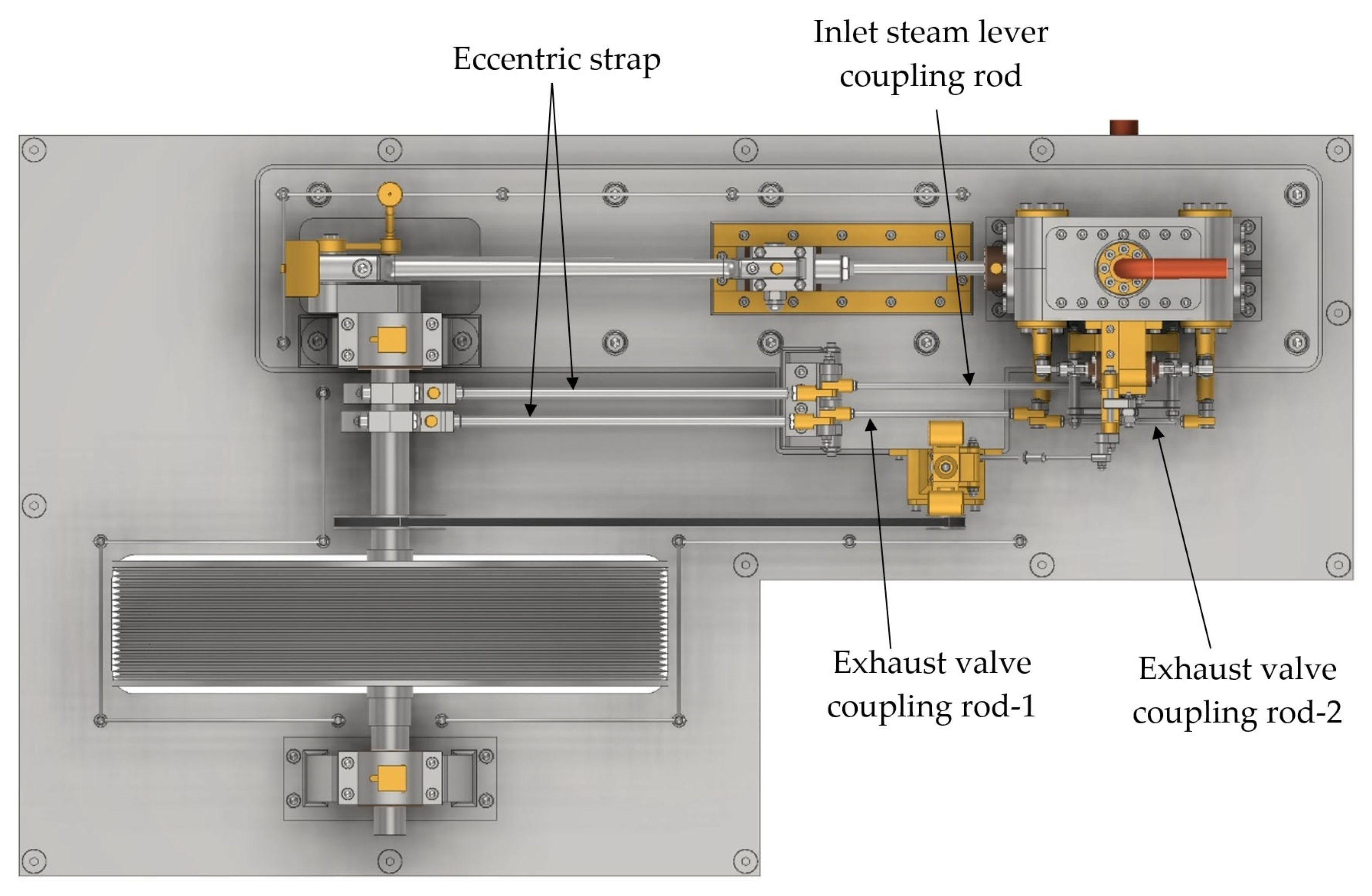
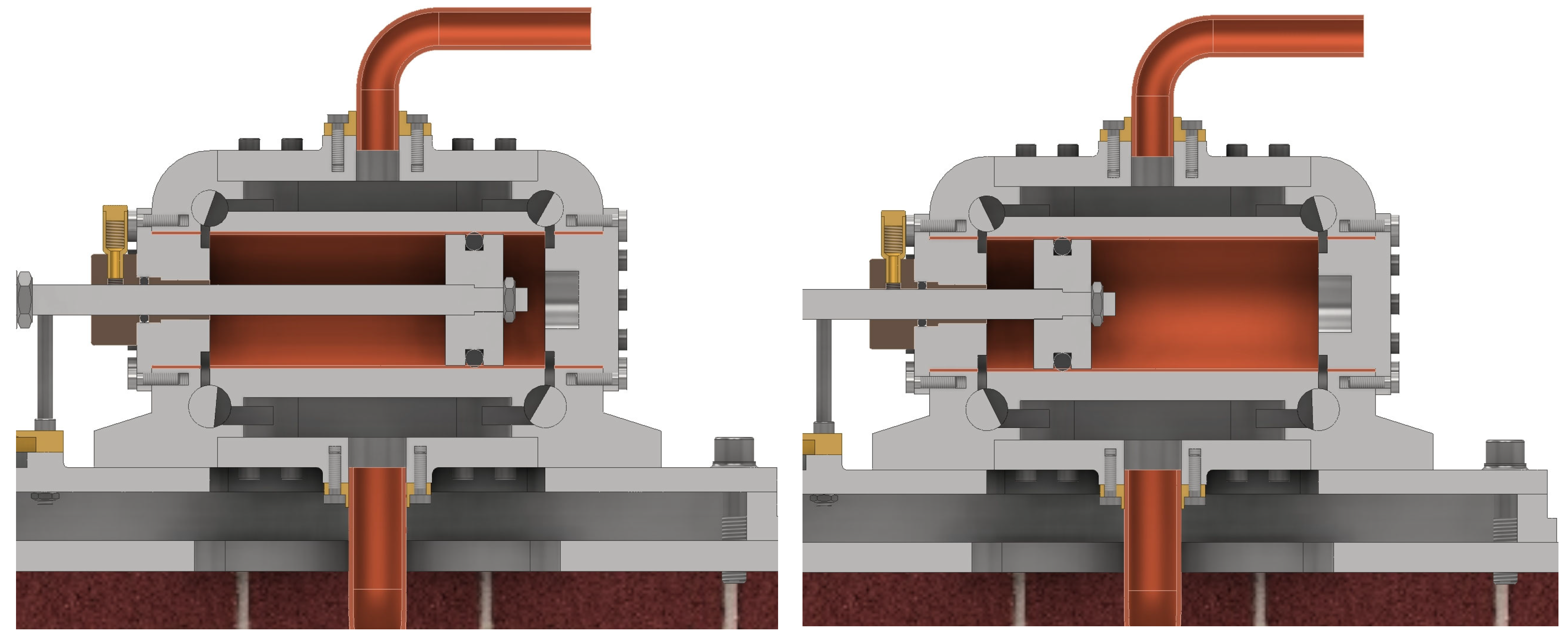
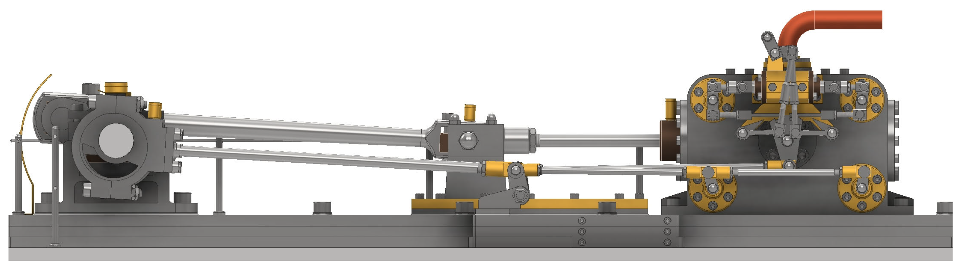
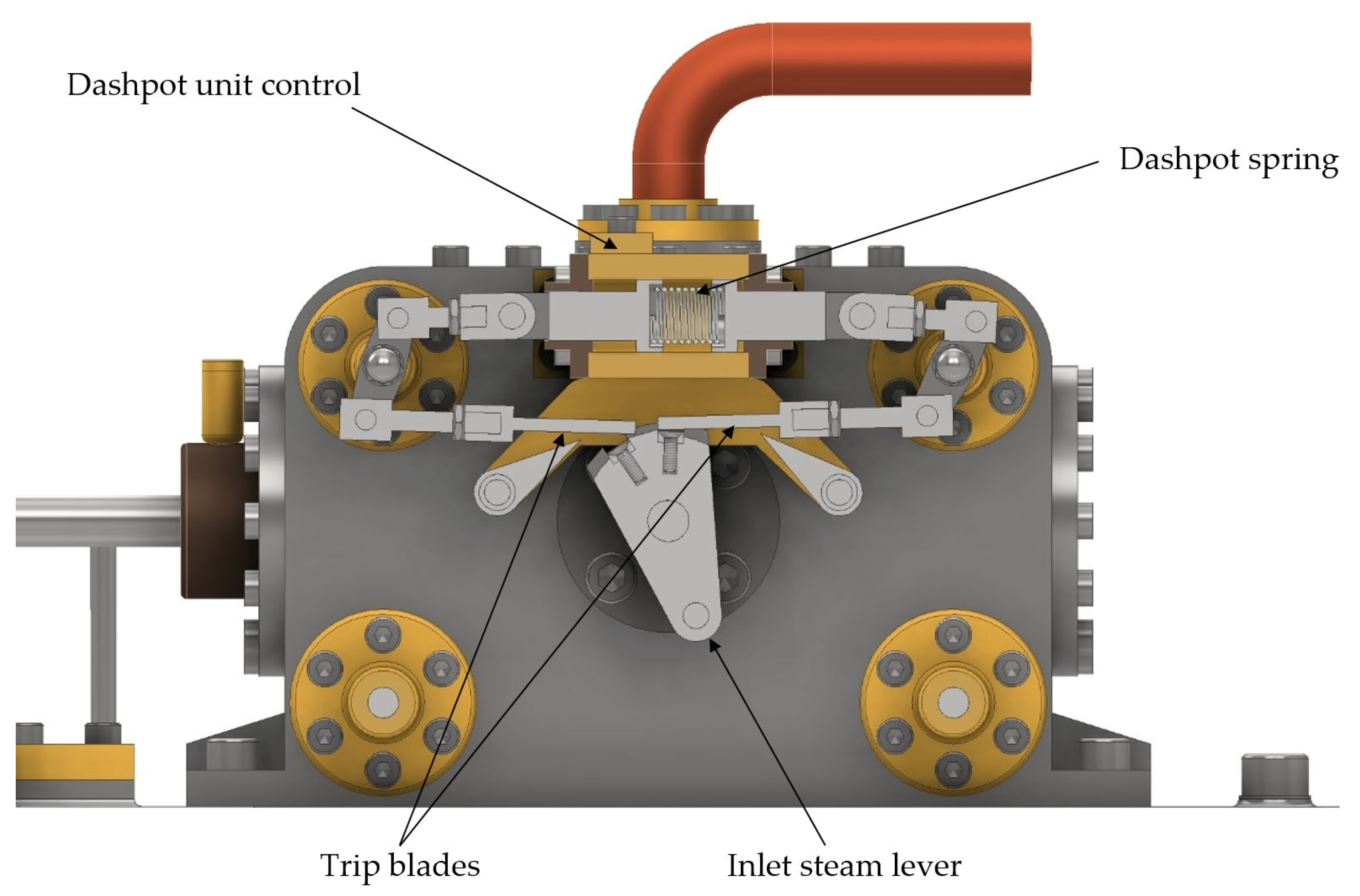
3.1. Corliss Valve Gear System

High-pressure steam enters the cylinder block (Figure 4), equipped with two inlet and two exhaust valves, inducing a linear reciprocating motion in the piston rod, assisted by the crosshead and connecting rod (Figure 5). The connecting rod converts this linear motion into rotational motion and is connected to the crankshaft to generate mechanical work. Each time the piston reaches one of the two dead centers (top dead center or bottom dead center), the steam is expelled to be condensed and the cycle is repeated.
The Corliss valve gear incorporated into this invention consists of four valves positioned at the corners of the cylinder block (Figure 6), with two dedicated to steam inlet located at the top of the cylinder block and two for steam outlet, located at the bottom. These valves are actuated by the motion of the crankshaft through their connection to the eccentric strap via coupling rods (Figure 7), thus creating an automatic control of the steam flow within the cylinder.
Additionally, the inlet valves are influenced by the governor, which modifies the position of the cam levers (Figure 8), located at the front of the cylinder block, to stabilize steam intake and machine speed.
As previously mentioned, high-pressure steam enters the cylinder through one of the steam inlet valves. To allow for the piston’s return stroke, the steam outlet valve located at the opposite end must permit the passage of steam until the bottom dead center is reached. Thus, once the piston rod has retracted, the second inlet valve, which initially blocked the steam flow, positions itself to connect the steam intake to the cylinder. Simultaneously, the second outlet valve connects to the exhaust, causing the rod to move forward until it reaches the top dead center (Figure 9).

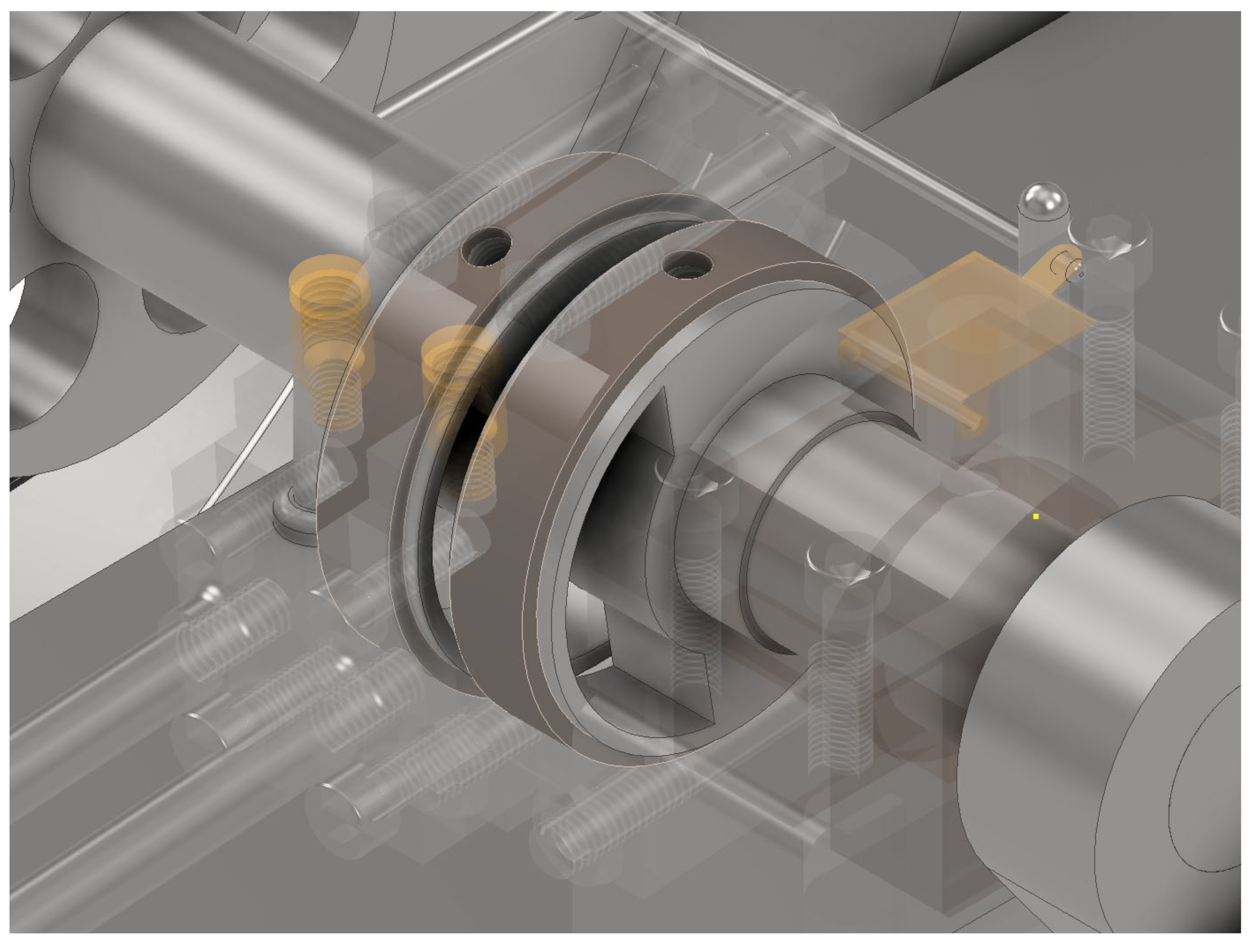
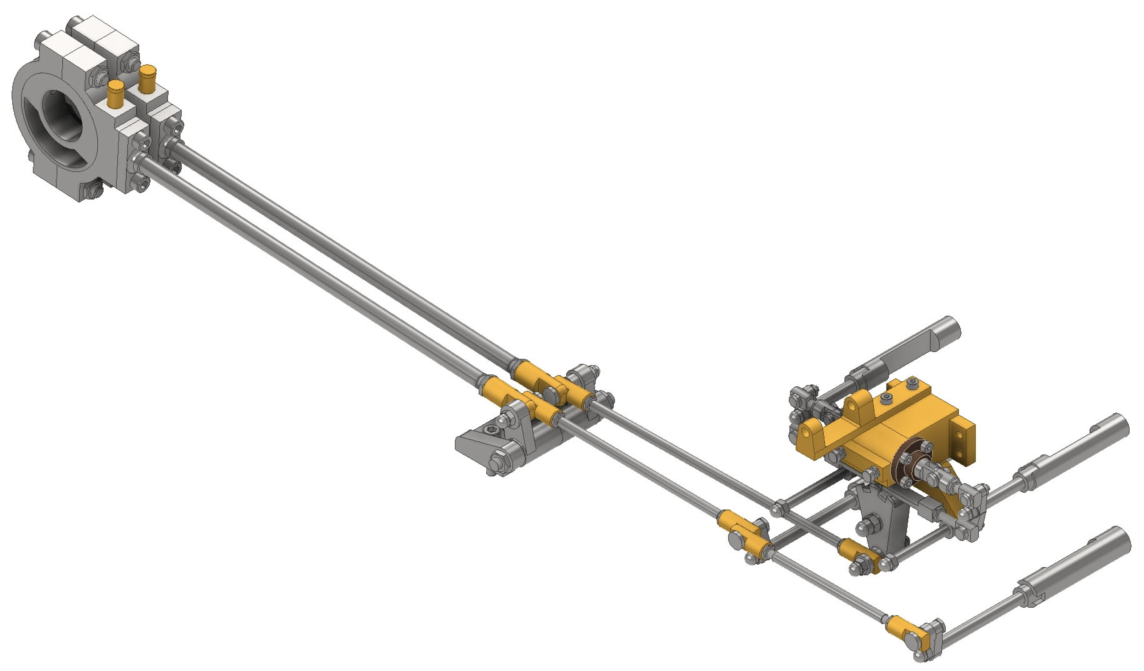
3.2. Influence of Eccentric Straps on Corliss Valve Gear System

The eccentric straps are responsible for actuating the valves via the coupling rods (Figure 10). The connection between the two is made through a single-arm valve rocker, which transmits the motion while being supported by a fulcrum bracket. Consequently, there are two eccentrics housed in the crankshaft of the invention, one dedicated to steam exhaust and the other to steam intake. In any given position of the crankshaft, the eccentric dedicated to admission is rotated 20° relative to the adjacent eccentric dedicated to exhaust (Figure 11), to synchronize the intake and exhaust of steam.
This is because the eccentric strap induces the movement of the exhaust valves through two coupling rods, causing the valves to rotate in the same direction as the eccentric strap. However, the eccentric dedicated to admission is connected to a single coupling rod, whose end connects to the inlet steam lever (Figure 12), allowing for rotation and enabling the displacement of the trip blades through their teeth, thus facilitating movement opposite to that obtained in the exhaust valves. Moreover, the trip blades are connected to each other by a dashpot spring housed in the cavity of the dashpot control unit (Figure 13).

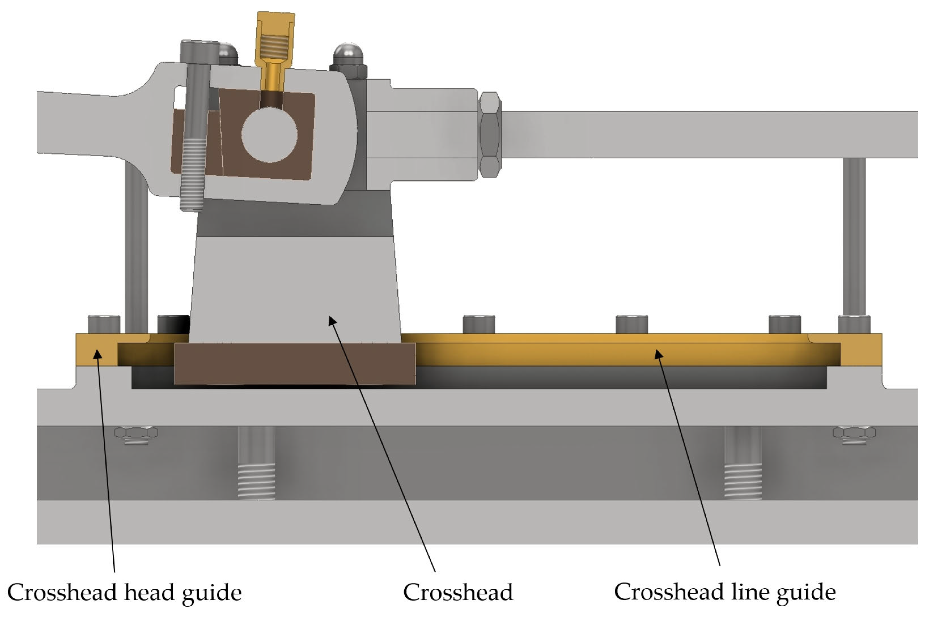
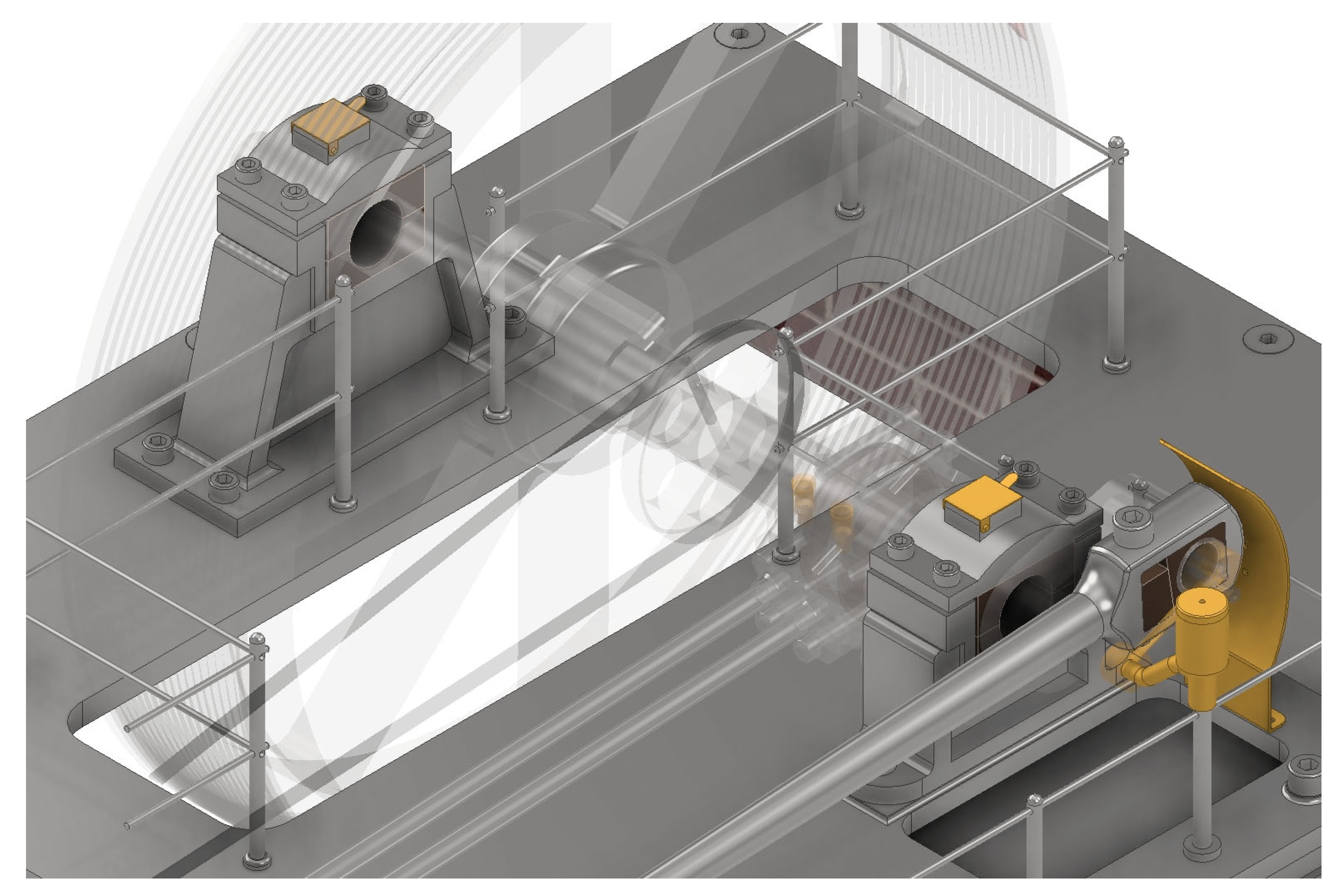
3.3. Crosshead System

To ensure the piston operates stably and efficiently within the cylinder and to prevent abrupt movements, a crosshead is employed. It serves as the connection between the piston rod and the connecting rod, joined to it via a pin (Figure 14). The crosshead is of paramount importance in the invention, as its restricted linear motion, guided by the crosshead guides fixed to the engine bedplate (Figure 15), prevents piston rotation. This prevents the transverse forces from the connecting rod from generating excessive stresses in the cylinder walls, thereby reducing component wear.

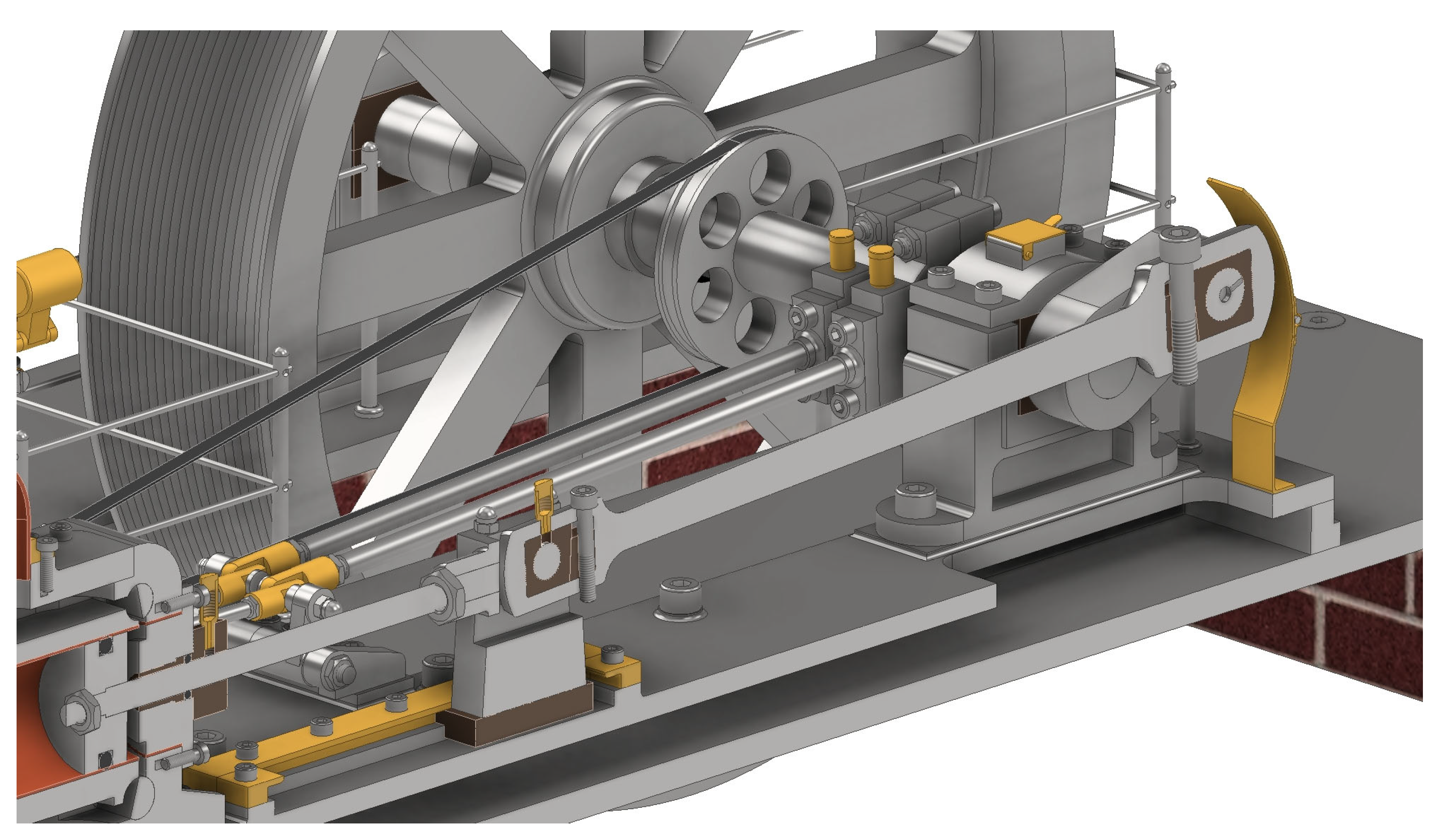
3.4. Operation of the Flywheel and Influence of the Crankshaft

The initial linear motion originating from the piston is driven by the force generated when high-pressure steam expands within the cylinder and is transmitted to the crosshead. This motion is transformed into a circular motion and transmitted to the crankshaft via the connecting rod due to the mechanical connection between these elements (Figure 16). Without the connecting rod, the proper functioning of the piston would be impossible, and difficulties would arise in the conversion between the two types of motion.
Moreover, the crankshaft is supported by two bearings at its ends, enabling rotation and accommodating the stresses that arise when the steam engine is in operation (Figure 17).
The induced circular motion causes the flywheel to rotate, secured to the crankshaft by a key within a keyway. Additionally, it enables the actuation of valves through eccentrics housed within the crankshaft, and the operation of the governor due to the solid rotation of the drive belt via the crankshaft pulley (Figure 18).
The flywheel’s function is to store kinetic energy and smooth out fluctuations in angular velocity. This is crucial because the components of the steam engine generate energy impulses intermittently, and thus the flywheel enables a more uniform and constant motion. Given these characteristics, and due to its toothed section (Figure 19), its function could be adapted for use in grinding grain, sugar cane, or similar materials.

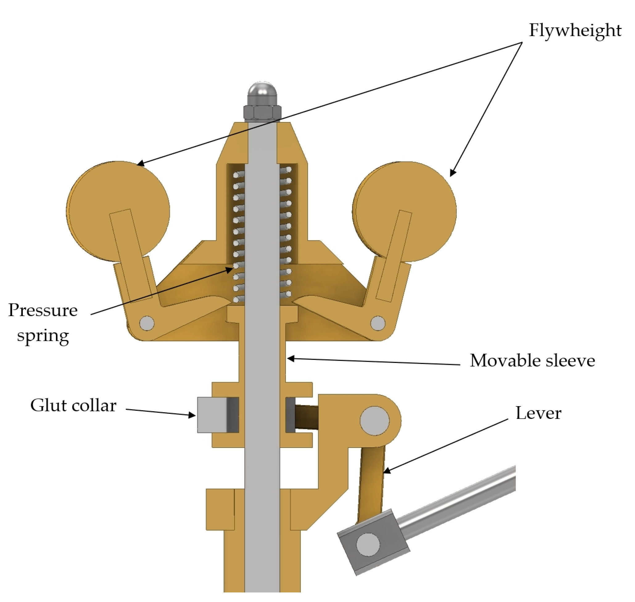
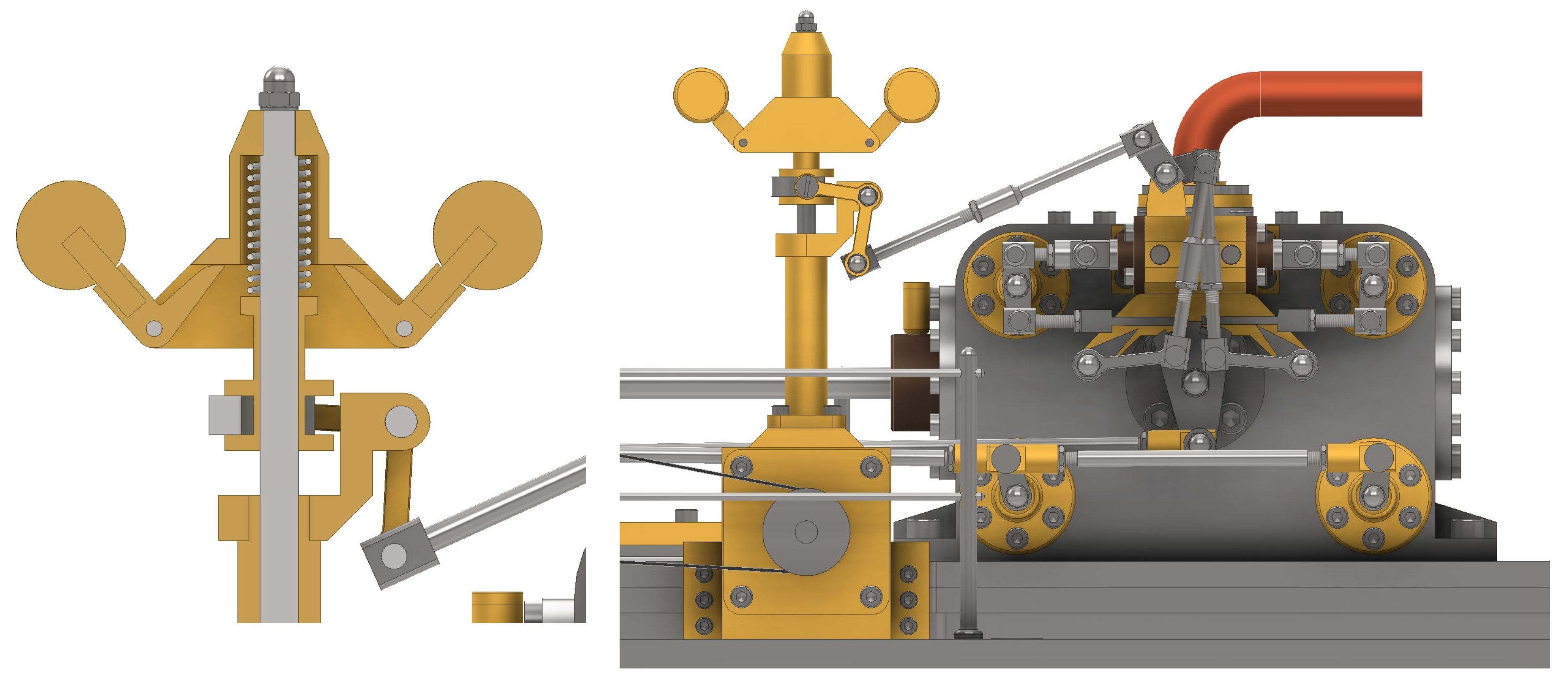
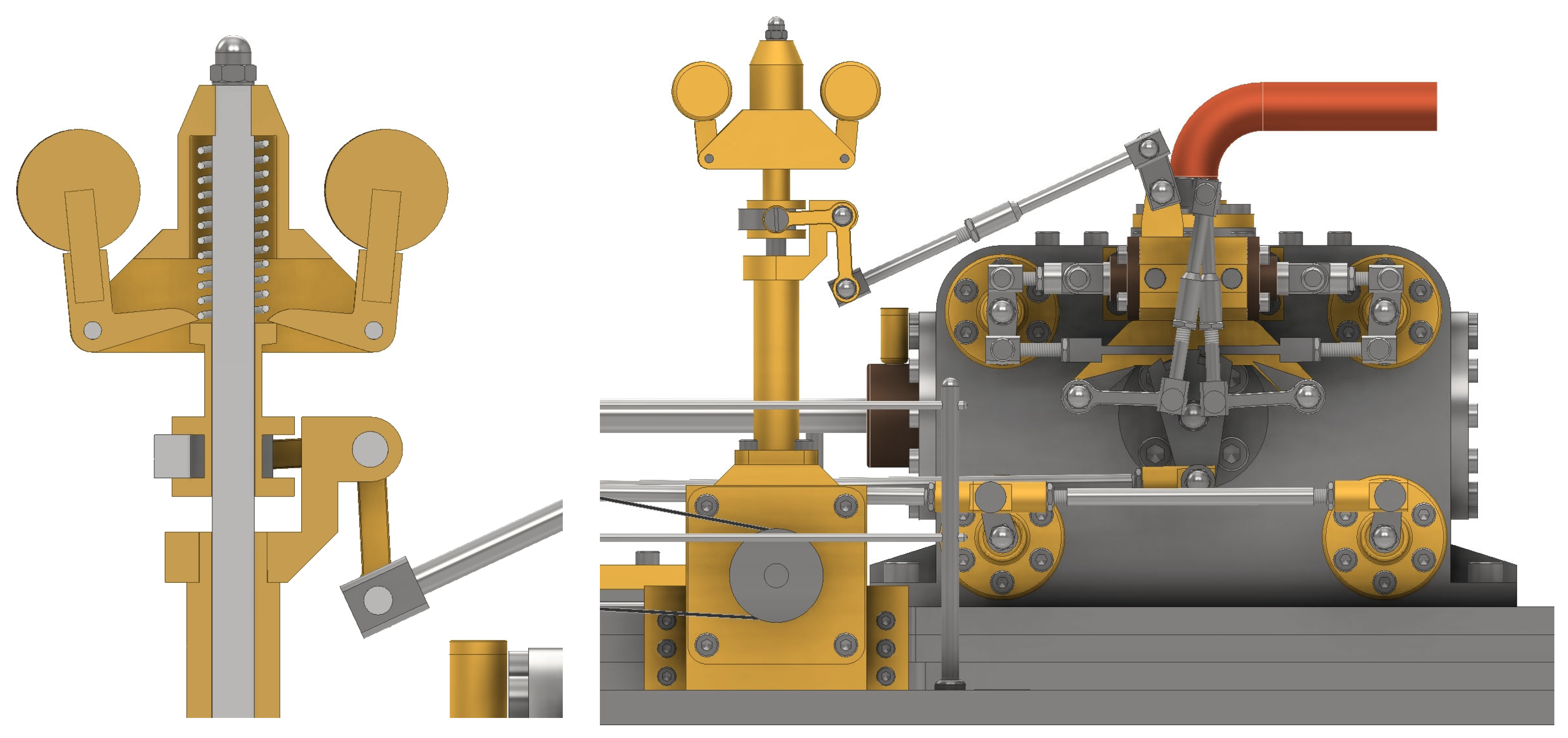
3.5. Governor System

The final significant system identifiable within the invention is the speed control system (Figure 20). This task is carried out by the governor, which ensures that the steam engine maintains a constant speed, regardless of variations in engine load. This is achieved through a mechanism that automatically adjusts the input steam supply to the cylinder.
Although the concept of a speed governor is straightforward, its implementation and operation can be complex due to various technical aspects. These include precision in terms of speed changes, the dynamic adjustment of steam supply in real time and continuously, the synchronization of the rotation of the counterweights with the steam valves, balance, and durability, among others.
As previously explained, the crankshaft transmits the rotational speed through pulleys and a drive belt (Figure 21). Once rotational motion is received on the governor shaft, it is then transmitted to the spindle via a system of bevel gears (Figure 22).
In addition to the small bevel gear housed in the spindle by means of a pin, it also consists of two flyweights and a movable sleeve enclosing the pressure spring. Furthermore, the regulation system extends from the lower part of the movable sleeve where the lever is fixed to a glut collar (Figure 23).
Therefore, the control system is determined by the dependence on the rotational speed of the crankshaft, or the linear motion of the piston, translating into an increase or decrease in the centrifugal force generated at the upper part of the spindle by the flyweights.
An increase in centrifugal force causes the position of the flyweights to change, such that the compressed dashpot spring contracts, raising the position of the movable sleeve (Figure 24).
Conversely, a reduction in speed results in a closer position of the flyweights and a decompression of the dashpot spring, causing the movable sleeve to descend (Figure 25). Thus, these elevation changes cause the movement of the cam levers that guide the trip blades through a system of mechanical linkages.

3.6. Corliss Valve Gear System Modeling Process

Subsequently, for greater clarity, the process of CAD modeling of all the components that make up the system of eccentrics and linkages that operate the Corliss valve gear system is presented (Figure 26).
The modeling process for each part is straightforward, as is the assembly, where the coincidence constraint offered by the software is used for each connection of the elements, including screws, nuts, and washers from the software’s material library, so that the operation of the invention can be accurately reproduced.
Starting from the origin of motion in the crankshaft, the first component is the eccentric (Figure 27), composed of two different materials, cast iron and bronze, so two separate parts must be modeled by material extrusion and then joined to form a subassembly.
This component is housed within the inner part of the eccentric strap (Figure 28). For the second part, connected to the previous piece by means of a base, a connecting rod is created, formed by revolving the sketch about the axis of symmetry (Figure 29), and the end is joined to other elements by means of a spindle (Figure 30).
The eccentric strap coupling connects to the fulcrum bracket (Figure 31) composed of a support (Figure 32) and a rod (Figure 33). Due to the symmetry of the design, only half of the component is modeled. Subsequently, it is completed using the symmetry function.
The connection between the fulcrum bracket and the eccentric strap is made through a single arm valve rocker (Figure 34), allowing the transmission of motion to the various coupling rods, two of which are destined for the exhaust valves and one for the inlet valve. Likewise, each is composed of a rod of different lengths (Figure 35) and two spindles (Figure 36).
Once all the mentioned elements are connected to each other using rods, washers, and nuts, they are connected directly to the exhaust valves or, in the case of the inlet valve, through a linkage system.
The steam exhaust valves (Figure 37) are connected to the coupling rods using a steam exhaust valve lever (Figure 38), while the steam inlet valve, connected to the trip blades and pistons where the dashpot spring is housed in the control unit, is connected by another steam inlet valve lever (Figure 39) with a similar geometry. The differences lie in the total length of the valves, with the exhaust valve being longer than the inlet valve, as well as the removal of material from the larger cylinder to create the valves. The levers are different, so care must be taken during assembly to ensure the correct operation of the steam engine. Additionally, this assembly is symmetrical with respect to the central plane of the cylinder block.
To enable the synchronized movement of the inlet valves from the coupling rod, a trip control lever (Figure 40) must be created. This lever rotates thanks to a steam lever trunnion (Figure 41) fixed to the cylinder block.
The oscillatory motion created drives a fully symmetrical linkage system. It consists of trip blades (Figure 42), directly connected to the inlet valves, and a damper system formed by two link rods (Figure 43) and two pistons (Figure 44), enclosing a dashpot spring (Figure 45) inside the control unit to limit the travel, connecting and synchronizing the valves.
Moreover, from the assembly perspective of the control unit, interest lies in the unit’s cavity (Figure 46) and the dashpot covers (Figure 47).
Finally, once the subassemblies have been modeled and created, the inlet valve linkage system is assembled, resulting in a final assembly (Figure 48). In this way, the functioning and movement of the valves that constitute the Corliss valve gear are reproduced.

4. Conclusions

This research presents a detailed engineering design, through CAD techniques, of a single-cylinder high-pressure steam engine with a Corliss valve gear, as designed by Arnold Throp. The design was achieved thanks to Autodesk Inventor Professional 2024 software.
The only available resources for this investigation were the original plans of the invention, published in the Model Engineer magazine in 1982 and reproduced by Julius de Waal in 2018. These plans provided dihedral projections of each component with their corresponding dimensions. However, during the digital restitution process, several deficiencies were identified, such as missing or incorrect dimensions for certain components. These challenges necessitated the implementation of various constraints to create a coherent and functional 3D CAD model, enabling a clear explanation of the machine’s operation to the interested reader and facilitating the dissemination of knowledge to the broader community.
Consequently, the most significant operating subsystems have been explained in detail, along with the influence of the eccentric straps on the Corliss valve gear. The modeling process of the valve gear system is also elaborated upon.
Furthermore, the research has revealed a notable symmetry in the governor’s structure and the arrangement of the four valves within the cylinder block, particularly in the mechanism that actuates the inlet valves. This symmetry is crucial for ensuring that forces and movements are distributed uniformly during the steam exchange within the cylinder, resulting in more balanced operation, reduced vibrations, and optimized overall efficiency of the invention.

Supplementary Materials

The following supporting information can be downloaded at: https://www.mdpi.com/article/10.3390/app15073587/s1. Video S1: Virtual Recreation.

Author Contributions

Conceptualization, J.I.R.-S.; Methodology, J.I.R.-S. and S.S.-G.; Investigation, J.I.R.-S. and S.S.-G.; Formal analysis, J.I.R.-S. and S.S.-G.; Visualization, J.I.R.-S. and S.S.-G.; Supervision, J.I.R.-S.; Writing—original draft preparation, J.I.R.-S. and S.S.-G.; Writing—review and editing, J.I.R.-S. and S.S.-G. All authors have read and agreed to the published version of the manuscript.

Funding

The research presented in this paper has been possible thanks to a collaboration grant from the Department of Engineering Graphics, Design and Projects of the University of Jaen, obtained in the 2024 call from the Ministry of Education and Vocational Training of the Government of Spain.

Institutional Review Board Statement

Not applicable.

Informed Consent Statement

Not applicable.

Data Availability Statement

The original contributions presented in the study are included in the article. Further inquiries can be directed to the corresponding author.

Acknowledgments

We would like to thank the anonymous reviewers of this paper for their constructive suggestions and comments.

Conflicts of Interest

The authors declare no conflicts of interest.

References

  1. Inkster, I. (Ed.) History of Technology; Bloomsbury Academic: London, UK, 2004; Volume 25. [Google Scholar]
  2. Thoendel, E. Simulation model of the thermodynamic cycle of a three-cylinder double-acting steam engine. Chem. Prod. Process Model. 2008, 3, 21. [Google Scholar] [CrossRef]
  3. Stokes, P.R. Piston steam engine innovation. Proc. Inst. Mech. Eng. Part A-J. Power Energy 1996, 210, 95–98. [Google Scholar] [CrossRef]
  4. Rojas-Sola, J.I.; Barranco-Molina, J.C. Engineering Drawing Applied to the Study of the Design of a Two-Cylinder Entablature dddSteam Engine with Parallel Motion Crosshead. Symmetry 2024, 16, 578. [Google Scholar] [CrossRef]
  5. Rojas-Sola, J.I.; Barranco-Molina, J.C. Analysis from the Functional Viewpoint of a Single-Cylinder Horizontal Steam Engine with a Crosshead Trunk Guide through Engineering Graphics. Symmetry 2024, 16, 722. [Google Scholar] [CrossRef]
  6. Yatsuzuka, S.; Niiyama, Y.; Fukuda, K.; Muramatsu, K.; Shikazono, N. Experimental and numerical evaluation of liquid-piston steam engine. Energy 2015, 87, 1–9. [Google Scholar] [CrossRef]
  7. Wang, Y.; Zhou, Z.J.; Zhou, J.H.; Liu, J.Z.; Wang, Z.H.; Cen, K.F. Micro Newcomen steam engine using two-phase working fluid. Energy 2011, 36, 917–921. [Google Scholar] [CrossRef]
  8. Ceccarelli, M.; Cocconcelli, M. Plans for a Course on the History of Mechanisms and Machine Science. In Trends in Educational Activity in the Field of Mechanism and Machine Theory; Springer: Cham, Switzerland, 2022; pp. 135–144. [Google Scholar] [CrossRef]
  9. Cocconcelli, M.; Ceccarelli, M. Italian teaching with models from mechanism catalogues in 19th century. In Explorations in the History and Heritage of Machines and Mechanisms; Springer: Cham, Switzerland, 2024; pp. 18–30. [Google Scholar] [CrossRef]
  10. Ceccarelli, M.; Cocconcelli, M. Italian historical developments of teaching and museum valorization of mechanism models. Machines 2022, 10, 628. [Google Scholar] [CrossRef]
  11. National Inventors Hall of Fame. George Henry Corliss. Improvements in the Steam Engine. Available online: https://www.invent.org/inductees/george-henry-corliss (accessed on 7 January 2025).
  12. Lucini, M.; Aleixandre, A.M. Máquinas de Vapor. Carburadores, Mezclas y Ejes; Litoprint: Madrid, España, 1972. (In Spanish) [Google Scholar]
  13. Inglis, W. On the Corliss expansion valve-gear for stationary engines. Proceeding Inst. Mech. Eng. 1992, 19, 177–194. [Google Scholar] [CrossRef]
  14. Li, J. The Corliss Steam Engine and the United States Economy in the Late Nineteenth-Century. Master’s Thesis, University of Delaware, Delaware, DE, USA, 2007. [Google Scholar]
  15. Rosenberg, N.; Trajtenberg, M. A General-Purpose Technology at work: The Corliss steam engine in the late-nineteenth-century United States. J. Econ. Hist. 2004, 64, 61–99. [Google Scholar] [CrossRef]
  16. Abrams, B.A.; Li, J.; Mulligan, J.G. Did Corliss Steam Engines Fuel Urban Growth in the Late Nineteenth Century? Less Sanguine Results. J. Econ. Hist. 2008, 68, 1172–1176. [Google Scholar] [CrossRef]
  17. Ferguson, E.S. Power and influence—The Corliss steam engine in the centennial era. Ann. N. Y. Acad. Sci. 1984, 424, 225–246. [Google Scholar] [CrossRef]
  18. Goodheart, A. The machine of the Myth + the Corliss-engine in machinery-hall at the centennial-exposition in Philadelphia 1876. Des. Q. 1992, 155, 24–28. [Google Scholar] [CrossRef]
  19. Throp, A. A model condensing Corliss engine: Part 1. Model Eng. 1982, 149, 223–224. [Google Scholar]
  20. Throp, A. A model condensing Corliss engine: Part 2. Model Eng. 1982, 149, 328–331. [Google Scholar]
  21. De Waal, J. Arnold Throp’s Corliss Condensing Engine. 2018. Available online: https://modelengineeringwebsite.com/Corliss_drawings.html (accessed on 7 January 2025).
  22. Chang, K.H. Design Theory and Methods Using CAD/CAE; Academic Press: London, UK, 2014. [Google Scholar]
  23. Jensen, C.H.; Branoff, T.J. Interpreting Engineering Drawings, 8th ed.; Delmar Cengage Learning: Independence, KY, USA, 2015. [Google Scholar]
  24. Paris, S.; Gattulli, V.; Landa, A.; Vannini, C. Protecting and redeveloping industrial archaeological heritage through design strategies driven by digital modelling. Conserv. Sci. Cult. Herit. 2023, 23, 331–348. [Google Scholar]
  25. Soler, J.J.C.; Ruiz, A.M.; Collazo, J.R. The “arte” of marble: An archaeological and digital approach to 19th century hydraulic sawmills in the Almanzora valley (Almeria, Spain). Virtual Archaeol. Rev. 2024, 15, 132–152. [Google Scholar] [CrossRef]
  26. Shults, R.; Levin, E.; Aukazhiyeva, Z.; Pavelka, K.; Kulichenko, N.; Kalabaev, N.; Sagyndyk, M.; Akhmetova, N. A Study of the accuracy of a 3D indoor camera for industrial archaeology applications. Heritage 2023, 6, 6240–6267. [Google Scholar] [CrossRef]
  27. Curra, E.; D’Amico, A.; Angelosanti, M. HBIM between Antiquity and Industrial Archaeology: Former Segre Papermill and Sanctuary of Hercules in Tivoli. Sustainability 2022, 14, 1329. [Google Scholar] [CrossRef]
  28. Principles of Seville on Virtual Archaeology. Available online: https://icomos.es/wp-content/uploads/2020/06/Seville-Principles-IN-ES-FR.pdf (accessed on 7 January 2025).
  29. London Charter. Available online: https://londoncharter.org (accessed on 7 January 2025).
  30. Choi, J.W.; Park, J.J.; Jun, H.J. An Interactive Virtual Reality Approach to Understanding Cultural Heritage Through Storyliving: A Case Study of Seoul City Wall (Hanyangdoseong) in South Korea. Appl. Sci. 2024, 14, 11348. [Google Scholar] [CrossRef]
  31. Zhu, G.; He, L.D.; Jia, X.Y.; Tan, Z.F.; Quin, Q.W. Experimental Study on Vibration and Noise Reduction of Gear Transmission System Based on ISFD. Machines 2024, 12, 531. [Google Scholar] [CrossRef]
  32. Kozanecki, D.; Wirowski, A.; Rabenda, M. Static and Dynamic Analysis of Bidirectionally Sinusoidal Corrugated Steel Shells-Comparative FEA Study. Appl. Sci. 2024, 14, 7936. [Google Scholar] [CrossRef]
  33. Varlik, A.; Dursun, I. Three-Dimensional Web-Based Client Presentation of Integrated BIM and GIS for Smart Cities. Buildings 2024, 14, 3021. [Google Scholar] [CrossRef]
  34. Shih, R.H.; Jumper, L. Parametric Modeling with Autodesk Inventor 2024; SDC Publications: Mission, KS, USA, 2023. [Google Scholar]
Figure 1. Front axonometric view of the ensemble.
Applsci 15 03587 g001
Figure 2. Rear axonometric view of the ensemble.
Applsci 15 03587 g002
Figure 3. Master assembly and subassemblies used in the modeling process.
Applsci 15 03587 g003
Figure 4. Cross-section of the intake and exhaust valves inside the cylinder.
Applsci 15 03587 g004
Figure 5. Axonometric view of the elements involved in transforming linear movement into circular movement.
Applsci 15 03587 g005
Figure 6. Cross-section of cylinder block showing the steam inlet and outlet valves (left) and steam inlet valve distribution (right).
Applsci 15 03587 g006
Figure 7. Top view of the ensemble showing the eccentric straps, inlet steam lever coupling rod, and exhaust valve coupling rods.
Applsci 15 03587 g007
Figure 8. Front view of the elements influencing the steam inlet valves.
Applsci 15 03587 g008
Figure 9. Cross-section of the cylinder block: piston rod reaching the top dead center (left) and reaching the bottom dead center (right).
Applsci 15 03587 g009
Figure 10. Axonometric view showing the eccentric straps and connection with coupling rods.
Applsci 15 03587 g010
Figure 11. Axonometric view showing the eccentric relative rotation.
Applsci 15 03587 g011
Figure 12. Cross-section showing the connection from eccentric to valves.
Applsci 15 03587 g012
Figure 13. Cross-section showing the elements influencing the rotation of intake valves.
Applsci 15 03587 g013
Figure 14. View of the ensemble, showing the elements of the crosshead system.
Applsci 15 03587 g014
Figure 15. Cross-section limiting elements of the crosshead.
Applsci 15 03587 g015
Figure 16. Cross-section of the ensemble of connecting rod, crosshead, and crankshaft.
Applsci 15 03587 g016
Figure 17. Axonometric view showing bearing supports of the crankshaft.
Applsci 15 03587 g017
Figure 18. Cross-section showing the connection of crankshaft and governor by the drive belt.
Applsci 15 03587 g018
Figure 19. Cross-section showing the toothed section of the flywheel.
Applsci 15 03587 g019
Figure 20. Front view of the elements forming the governor system.
Applsci 15 03587 g020
Figure 21. Axonometric view of the ensemble of the crankshaft and control speed system.
Applsci 15 03587 g021
Figure 22. Right view of the connection of shaft and spindle by bevel gears.
Applsci 15 03587 g022
Figure 23. Cross-section of the components of the governor spindle.
Applsci 15 03587 g023
Figure 24. Cross-section of the governor at maximum speed (left) and influence on the cam lever position (right).
Applsci 15 03587 g024
Figure 25. Cross-section of the governor at minimum speed (left) and influence on the cam lever position (right).
Applsci 15 03587 g025
Figure 26. Axonometric view of the elements forming the Corliss valve gear system.
Applsci 15 03587 g026
Figure 27. Design of the part of the eccentric made with cast iron (left) and the part made with bronze (right).
Applsci 15 03587 g027
Figure 28. Design of the first part of the eccentric strap.
Applsci 15 03587 g028
Figure 29. Design of the connecting rod through revolution of the sketch.
Applsci 15 03587 g029
Figure 30. Design of the spindle through extrusion and edge rounding.
Applsci 15 03587 g030
Figure 31. Fulcrum bracket.
Applsci 15 03587 g031
Figure 32. Design of the fulcrum bracket through extrusion and symmetry.
Applsci 15 03587 g032
Figure 33. Rod.
Figure 33. Rod.
Applsci 15 03587 g033
Figure 34. Design of the single arm valve rocker through extrusion.
Applsci 15 03587 g034
Figure 35. Three types of rod designed through extrusion: (a,b) related to steam exhaust and (c) related to steam intake.
Applsci 15 03587 g035
Figure 36. Design of the spindle through extrusion.
Applsci 15 03587 g036
Figure 37. Design of the steam exhaust valve through extrusion, casting, and revolution.
Applsci 15 03587 g037
Figure 38. Design of the steam exhaust valve lever (left) and its assembly (right).
Applsci 15 03587 g038
Figure 39. Design of the steam inlet valve lever (left) and its assembly (right).
Applsci 15 03587 g039
Figure 40. Design of the trip control lever.
Applsci 15 03587 g040
Figure 41. Design of the steam lever trunnion.
Applsci 15 03587 g041
Figure 42. Design of the trip blades through extrusion and revolution.
Applsci 15 03587 g042
Figure 43. Design of the link rod through extrusion and revolution.
Applsci 15 03587 g043
Figure 44. Design of the dashpot spring through extrusion and revolution.
Applsci 15 03587 g044
Figure 45. Design of the dashpot through the ‘coil’ function.
Applsci 15 03587 g045
Figure 46. Design of the control unit through extrusion.
Applsci 15 03587 g046
Figure 47. Design of the dashpot cover through revolution and extrusion (left) and its assembly (right).
Applsci 15 03587 g047
Figure 48. Cross-section of the final assembly.
Applsci 15 03587 g048
Disclaimer/Publisher’s Note: The statements, opinions and data contained in all publications are solely those of the individual author(s) and contributor(s) and not of MDPI and/or the editor(s). MDPI and/or the editor(s) disclaim responsibility for any injury to people or property resulting from any ideas, methods, instructions or products referred to in the content.

