Article

Development of a Laser Surgical Device with Vibration Compensation: Mechanical Design and Validation of Its Compliant Mechanism

by
Emil Ionuț Niță
1,
Daniel C. Comeagă
1,†,
Dragos A. Apostol
1,† and
Virgil-Florin Duma
1,2,*,†
1
Center of Research and Development for Mechatronics, National University of Science and Technology POLITEHNICA Bucharest, 060042 Bucharest, Romania
2
3OM Optomechatronics Group, Department of Measurements and Optical Electronics, Faculty of Electronics, Telecommunications, and Information Technology, Polytechnic University of Timisoara, 300006 Timisoara, Romania
*
Author to whom correspondence should be addressed.
These authors contributed equally to this work.
Appl. Sci. 2025, 15(7), 3686; https://doi.org/10.3390/app15073686
Submission received: 27 October 2024 / Revised: 16 March 2025 / Accepted: 24 March 2025 / Published: 27 March 2025
(This article belongs to the Section Applied Physics General)

Abstract

:

Featured Application

The future applications of this work are focused on the development and testing of a handheld laser surgical device that is designed to attenuate vibrations produced by hand tremors.

Abstract

Mitigating hand tremors in surgical applications has a critical role in laser-based medical procedures. We report the development of a proof-of-concept 3 degrees of freedom (DOF) hand vibration compensation device that features a compliant mechanical structure with three stack-type piezoelectric actuators. Inspired by the Stewart-type mobile platform, the system has the capability to manipulate a laser beam in two directions. In the present work, the mechanical part of the device is designed, and its mathematical model is developed. Also, the manufacturing of the proposed platform is presented, and the precision of its parts is assessed. An in-house developed mechanical stand is designed and utilized in order to perform a static analysis of the linkage amplification mechanism. Both a finite element analysis (FEA) and experimental validations of this mechanism are performed. A good match is obtained between the results obtained with the two methods. An analysis of the errors is made in order to assess the mechanical aspects of the platform. The study lays the foundation for the further development of the mechatronic and optical parts of the system, as well as for its miniaturization.

1. Introduction

Hand tremors can be a significant challenge for surgeons, as they can interfere with fine motor skills and precision. Thus, even a subtle tremor can have detrimental effects. This may lead to inaccurate incisions, tissue damage, and an increased risk of complications. Therefore, it can potentially compromise the patients’ safety, as well as the expected surgical outcomes [1,2,3].
This challenge is observed across a range of medical applications, and it is not confined to surgery alone. For example, for medical imaging using handheld probes [4,5,6,7,8], hand tremors have been approached by developing specialized software for the post-processing of images in order to compensate for their effects [9]. The main approach in hand tremor cancelation has been to position the tools on platforms manipulated by robotic arms around the patient [10,11,12,13,14,15]. This has had drawbacks, such as reduced mobility and a narrow field-of-view (FOV) due to teleoperation, as well as a low versatility of the system in unpredictable situations. The benefits and drawbacks of robot-assisted surgery compared to traditional surgery were discussed in a comprehensive way in [16].
In general, hand tremors can be categorized into two main types [17,18,19]:
(1)
Resting tremor, which occurs when the hands are relaxed, without any intentional movement. It is the most common type of tremor and is often associated with medical conditions such as essential tremor or Parkinson’s disease.
(2)
Action tremor, which occurs during voluntary movements, such as holding surgical instruments or performing (delicate) procedures. It can be exacerbated by factors such as fatigue, stress, and anxiety, all of which are often present in surgical environments.
In surgery, hand tremors can significantly impact, in several ways, the performance and outcomes of the medical act through the following:
  • Reduced precision and accuracy: hand tremors can cause surgeons to perform inaccurate incisions. This leads to tissue damage and potential complications.
  • Increased procedural time: trying to compensate for hand tremors can make surgical procedures longer. This can be detrimental to the patient’s safety.
  • Emotional distress: surgeons with hand tremors may experience anxiety and self-doubt. This can further impair their performance and increase the risk of errors.
For laser microsurgery (i.e., where a laser scalpel is utilized) [20,21,22] the impact of the hand tremor is even more severe, as it can lead to additional complications, including:
  • Inaccurate tissue removal: uncontrolled hand tremors can lead to uneven or imprecise tissue removal. This potentially affects the effectiveness of the procedure.
  • Targeted tissue damage: hand tremors can cause an unwanted deviation from the intended target. This results in unintentional tissue damage or collateral injury.
  • Excessive procedural complexity: compensating for hand tremors can make surgery more challenging and time-consuming.
  • Increased risk of complications: imprecise surgery can increase the risk of complications such as bleeding, infection, and scarring.
To mitigate the impact of hand tremors in the microsurgery field, and especially in eye surgery, surgeons and researchers have adopted innovative strategies [23] based on:
  • Robotic stabilization devices: fully robotic solutions, robotic-assisted systems such as Steady Hand [24,25], or stabilization tools can compensate for tremors. Thus, they can ensure a more precise laser application. These devices translate surgical movements into steady, calculated actions.
  • Handheld stabilization devices: handheld tools such as Micron (in its multiple versions) [22,25,26] have been designed to monitor and minimize the impact of hand tremors during surgical procedures. Thus, they could offer a blend of flexibility and precision.
  • Computational power evolution: modern laser systems integrate tracking mechanisms in order to maintain alignment with retinal targets, even if minor hand tremors occur [27,28].
  • Enhanced training programs: surgeon training programs emphasize fine motor skills and techniques for minimizing hand tremors [29]. Simulation-based training provides opportunities to practice in controlled environments. Thus, they reduce errors during actual surgeries using dedicated tools [30].
An example of laser applications in the field of eye surgery is laser photocoagulation, which is a precise, minimally invasive ophthalmic procedure utilized for treating various retinal conditions [20]. It involves the application of laser energy to specific areas of the retina in order to create controlled burns or coagulation. These burns help to stabilize or improve retinal health by sealing blood vessels, reducing abnormal growth, or reinforcing retinal adhesion. This type of surgery requires a high level of precision and robotic assistance if performed manually. Advantages of the proposed laser surgical device with vibration compensation include better precision for surgery, availability, as well as flexibility. For the latter two aspects, one can perform surgery in areas where high-performance (e.g., robotic) systems are not available or for emergencies. Drawbacks are related to the dimensions of the system, which is larger than a conventional laser scalpel that only carries an optical fiber for the laser.
Numerous studies have approached new methods for tremor attenuation in the surgery field [31,32], from wearable devices such as bracelets and exoskeletons [33,34,35] to robotic approaches. Considering only handheld mechatronics solutions, modified Stewart platforms with or without compliant mechanisms have been utilized for handheld devices capable of hand tremor compensation [35,36,37]. This is the approach we have been considering in our line of studies, as well. Other solutions found in the literature are based on bimorph piezo actuators [38] or on microlinear stages [39]. Considering the focal point of the laser as the tool tip for which the hand tremor has the highest impact, an intended laser beam deviation using prisms or acousto-optic deflectors has been studied. Another approach has involved developing extended robotic arms that hold surgical instruments and are controlled directly by the surgeon. The latter solution can blend the precision of robotics with the dexterity and fluidity of human movement.
The scope of the above is to design a surgical device capable of minimizing the impact of the surgeon’s hand tremor Therefore, it is essential to analyze the specific characteristics of the tremor occurring at the surgeon’s hand level, along with its mechanical properties.
First, the type of hand tremor that must be considered is physiological, not pathological. This means that it is always present in all people. Such a type of tremor is characterized by its oscillation frequency and by the tremor amplitude. The frequency of the tremor varies from person to person, depending on the biological motor system. It is roughly located in the frequency band of 5 to 15 Hz [40,41,42]. The amplitude of the tremor varies, depending on external and internal factors such as emotional state, caffeine level, sleep schedule, etc. For microsurgeons [38], it typically reaches values of 150 μm peak-to-peak [22,40,43], but it does increase with age. A second important aspect of tremor influence is its direction of travel. Tremor appears on all 6 DOF at the hand level (i.e., three translations and three rotations in an orthogonal system positioned at the wrist level) [44,45,46]. This becomes challenging for both signal acquisition and processing, especially when it is required to separate the useful signal (i.e., the surgeon’s hand movement) from the unwanted signal generated by the tremor.
Considering the above, the aim of this work has been to develop a modified Stewart-type platform model with 3 DOF as a proof-of-concept for the proposed surgical device with vibration compensation. The main feature of the proposed device is the compliant structure that allows for fine positioning. In this respect, the schematics and the mathematical model must be first developed, within certain (necessary) limitations. Specifically, the focus of the present paper (which is the first in this direction of study) is to develop a compliant amplifier mechanism that provides an extended range of motion, which is required in order to compensate for a 150 μm peak-to-peak hand tremor amplitude.
An innovative experimental testing method that combines a high-resolution optical 3D measuring system with a material testing machine has been adopted in order to obtain the best possible results. Additionally, high-precision measurement instruments are considered to ensure the quality of the testing procedure. The experimental validations must confirm the developed 3D model of the amplifier, assess the mechanical properties of the chosen material, as well as the static performance of the compliant mechanism. Also, some preliminary dynamic results are necessary to determine the useful frequency range of the mechanism.

2. Design of the Laser Scalpel

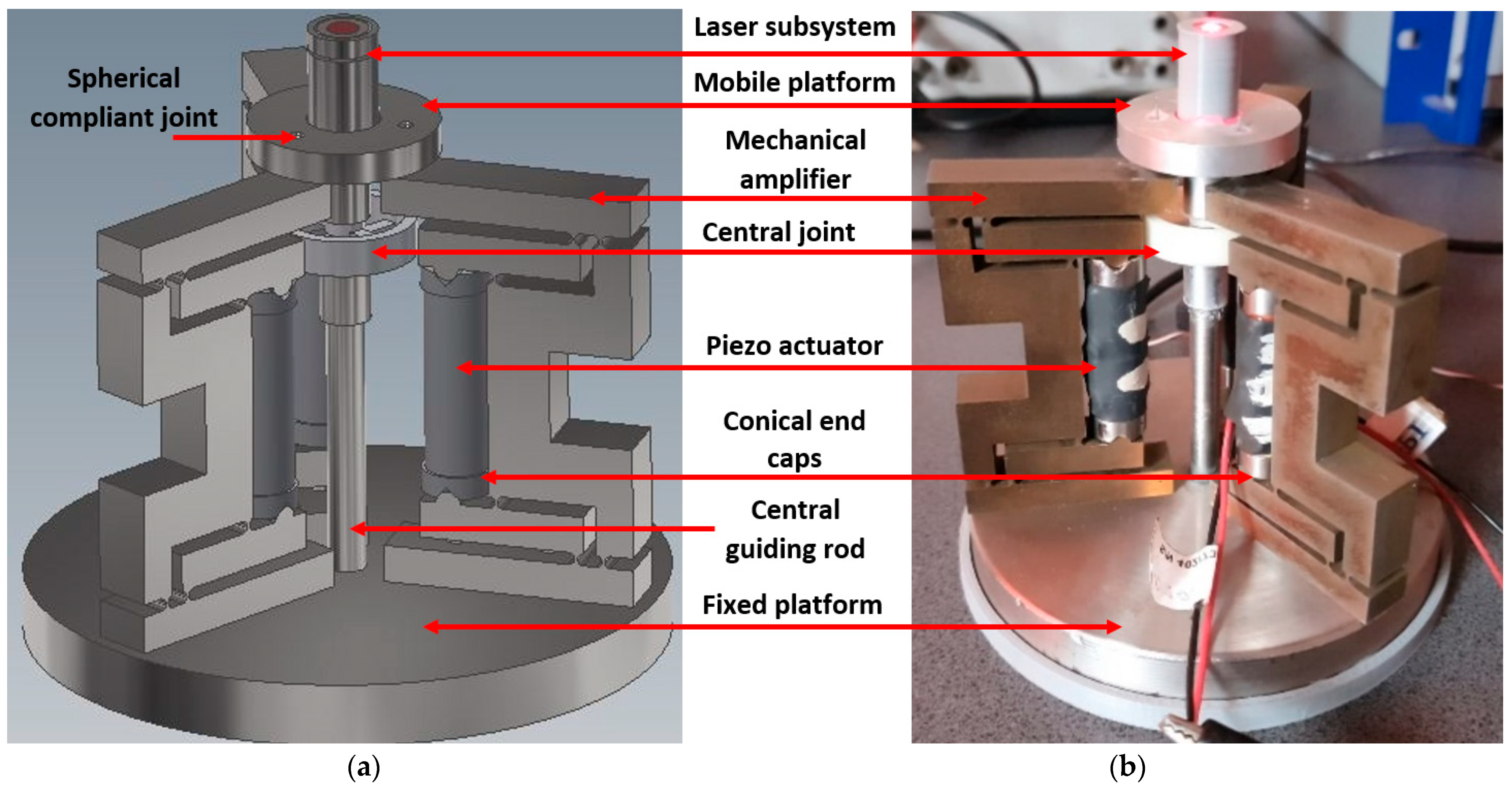
2.1. General Structure and Components

To gain a better understanding of the research subject, Figure 1a illustrates the 3D model of the fully assembled device that integrates three mechanical amplifiers.
Figure 1b presents the physical device, in this proof-of-concept stage, highlighting its key components:
Laser subsystem: the element responsible for the collimation of the laser beam that is used for cutting, ablation, or controlled burning during surgical procedures. A laser diode source with a center wavelength of 808 nm (considered for proof-of-concept testing), with a red pilot beam is utilized.
Mobile platform: the component that moves together with the laser subsystem to adjust the position of the laser spot on a target plane in order to compensate for any unintended hand movements made by the surgeon. It is equipped with sensing electronics that allow for monitoring movements across all six DOF.
Compliant spherical joints: the component represented by a metal wire that transmits the motion from the mechanical amplifier to the mobile platform.
Mechanical amplifiers: the mechanisms that transmit and amplify the movements generated by the piezoelectric actuator, thus enabling the compensation of vibrations with the level of precision that can be achieved.
Central joint: the pivot point that allows for a controlled movement of the mobile platform, thus eliminating parasitic movements. It facilitates only two rotations and a slight displacement (i.e., translation) along the optical axis and the laser terminal.
P-010.20 piezo actuators: they are responsible for generating the fast and precise movements required to counteract unintended vibrations. This type of actuator provides a high resolution and a short response time, thus making it an appropriate choice for active vibration compensation.
Conical end caps: they are utilized to secure and self-center the piezoelectric actuators, therefore minimizing the bending stress on the stack.
Central guidance rod: it is made of an aluminum alloy; it serves to rigidly connect the central joint to the support platform, and it allows for routing signal/power wires through its interior.
Support platform: the base of the system that ensures the stability of the entire structure and maintains all the components in their correct positions. It is the point from which the operator holds the system, as well as the area where the hand vibrations are measured.
A discussion should be made at this point, before starting the design and analysis process, regarding the necessary number of DOF of the proposed system. Thus, depending on the application, a translation along the optical axis of the laser may or may not be required. In applications involving tissue removal, such as plastic microsurgery, the precise control of laser focusing is not essential. Vibrations along the optical axis caused by hand tremors are within acceptable limits (considering the amplitude of the tremor in this direction) and can be disregarded. However, in other applications, such as the manipulation of nerve endings or high-precision laser scanning of surfaces, focus control becomes critical, making the axial translation of the device indispensable.
The current structure of the device has been designed as a platform that can be further developed for various applications. The functionality demonstration has been focused solely on rotational movements for two primary reasons. First, the intended application is surgery involving tissue removal. Second, active vibration compensation using translational piezoelectric actuators (with or without compliant mechanisms) is already a well-established technique, which is extensively documented in the specialized literature and is available in commercial products.
In a 3 DOF device, controlling translation along the laser axis requires the simultaneous operation of all three actuators, which does not pose significant challenges. Transitioning to a 2 DOF application could theoretically be achieved by simplifying the mechanism, eliminating one actuator, and removing the translation component from the central compliant mechanism, thus leaving only two rotational movements integrated with the central rod. However, a major issue would arise in such a case from the well-known recommendation that piezoelectric actuators should not operate under traction force. Consequently, in a configuration with only two actuators, the compensation range would be halved, as the actuators would be capable only of elongation and not of contraction.
Therefore, the use of three actuators allows for a modification of the reference plane of the mechanism, enabling a significantly broader range of motion, even when the actuators operate exclusively in elongation mode. This consideration ultimately led to the decision to maintain the current structure of the device, even when utilized solely for cutting operations, a case in which compensation is required only for the surgeon’s hand.
Another important aspect refers to the central joint of the device, which is presented in detail in Figure 2. A rigid central column extends along the laser beam axis, reaching close to the upper platform. At its upper end, a compliant joint is connected between the column and the platform. This mechanism constrains the system to 3 DOF and fully supports the mass of the platform while restricting any additional DOF. The steel wires (i.e., the spherical joints described above) serve exclusively as transmission elements, relaying motion from the actuators to the platform without contributing to its support or to the dynamic response. As the piezo actuators operate only in an extensional mode, the compliant mechanism ensures that the resulting motion at its output is always directed downward. Consequently, the mechanism exerts a pulling force on the platform through the steel wires, never pushing it upward. Due to this unidirectional force transmission, the elastic wires can be replaced with thin filaments. However, such filaments require a precise assembly in order to maintain a high pre-tensioning. This can be challenging from a constructive point of view. The use of highly flexible wires simplifies the assembly process and introduces a pseudo-spherical joint at the connection points. Nevertheless, the stiffness of this joint is negligible compared to both the central support mechanism and the compliant structure of the actuators.
As a result, the system consists of three mechanical amplifiers that pull the mobile platform via super-elastic filaments, with the platform being supported by a central joint providing 3 DOF. This adopted technical solution provides the necessary function of the devices, while it simplifies the construction of the system. It represents one of the original contributions of the present study.

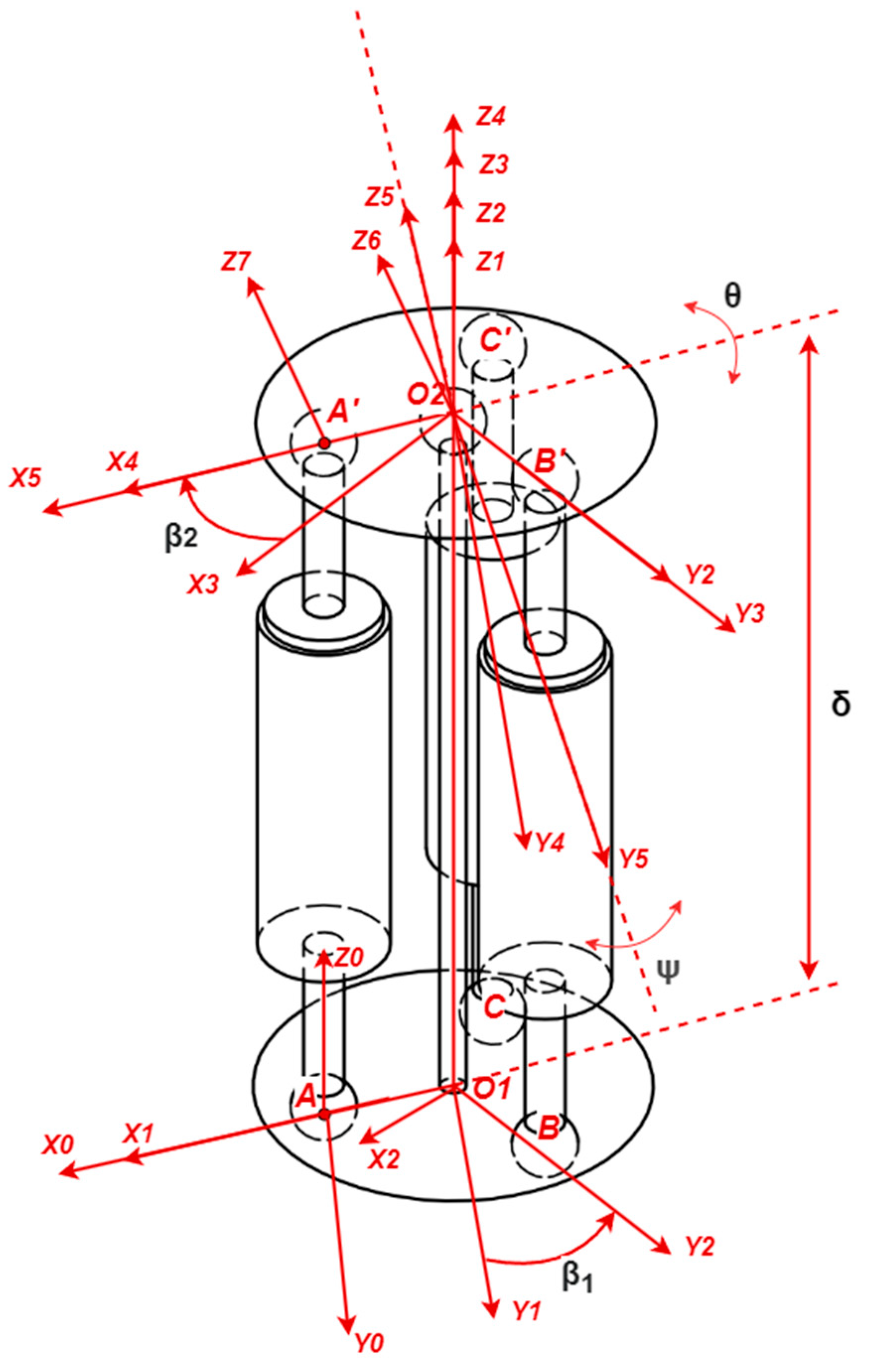
2.2. Schematic Diagram for a Modified Stewart Platform

The schematic of the mechanical part of the designed system is presented in Figure 3. One may observe certain structural differences between the real model shown in Figure 1 and the schematics presented in Figure 3. These differences arise from the larger structure of the mechanical amplifier, as this variant has been designed as a demonstrator. Thus, the mechanical amplifier should have two spherical joints at both ends (as presented in Figure 3). However, the weight of the actuation subassembly (i.e., the actuator–amplifier mechanism) that resulted from the first iteration, with a mechanism that could not be supported by two short metal wires located above and below was rather important. Therefore, we decided to connect the mechanical amplifiers directly to the support platform, as shown in Figure 1 and Figure 2, and as explained in the previous subsection.
This has led to a problem of blocking the movement of the mobile platform because the classic mechanism that was obtained is indeterminate. To tackle this aspect, we have proposed a solution that involves using a longer metal wire, which allows for deformation in the shape of the letter “S”. This solution is not easily reducible to a conventional mechanism; therefore, we have been planning on studying the optimal equivalence variants according to the theory of compliant mechanisms [47,48,49]. However, this is beyond the scope of this work. Therefore, for the present study the classic theoretical configuration presented in Figure 3 is analyzed, with the validation of the error in the actual system to be addressed in a future work.
In order to develop the mathematical model of the desired configuration, the distance AA′ must be defined in relation to the three input parameters: the rotations ψ and θ around the X4 and Y4 axes, respectively, as well as the translation δ along the optical (i.e., Z) axis of the plane that is determined by A′B′C′ in relation to the X0Y0Z0 coordinate system (where the latter is considered fixed). The input parameters are determined by the acquired hand tremor signal that must be processed in order to optimally determine the two rotation angles θ and ψ, but also by the translation δ of the optical element.
The main scope of developing the mathematical model is to determine the coordinates of point A′ in the system of coordinates X0Y0Z0. Also, the distance AA′ that determines the control signal of the actuators must be ascertained. The transformation matrix from the X0Y0Z0 coordinate system to the X5Y5Z5 coordinate system is given by the equation
H 0 7 = T r a n s 0 1 A O 1 , 0   0 · R o t Z 1 2 β 1 · T r a n s 2 3 0,0 , δ · R o t Z 3 4 β 2 · R o t X 4 5 θ · R o t Y 5 6 ψ · T r a n s 6 7 A O 2 , 0   0 ,
where: Trans01 (x, y, z) represents the translation matrix from the X0Y0Z0 coordinate system to the X1Y1Z1 coordinates system; Trans23 (x, y, z) represents the translation matrix from the X2Y2Z2 coordinate system to the X3Y3Z3 coordinates system; Trans67 (x, y, z) represents the translation matrix from the X6Y6Z6 coordinate system to the X7Y7Z7 coordinates system when performed with the x, y, and z distances; Rotz121) represents the rotation matrix around the Z1 axis of the input coordinate system X1Y1Z1 to the final coordinate system X2Y2Z2, performed with the angle β1; Rotz34 (−β2) represents the rotation matrix around the Z3 axis of the input coordinate system X3Y3Z3 to the final coordinate system X4Y5Z4, performed with the angle −β2; RotX45 (θ) represents the rotation matrix around the X4 axis of the input coordinate system X4Y4Z4 to the final coordinate system X5Y5Z5, performed with the angle θ; RotY56 (ψ) represents the rotation matrix around the Y5 axis of the input coordinate system X5Y5Z5 to the final coordinate system X6Y6Z6, performed with the angle ψ.
The coordinates of the point A′ in the X0Y0Z0 system of coordinates are given by
x A y A z A 1 = H 0 7 * x A , y A , z A , 1 .
Considering Equations (1) and (2), the AA′, BB′, and CC′ distances can be obtained. They represent the displacement of the actuators under the action of the input parameters (i.e., the rotations θ and ψ, as well as translation δ). The AA′ vector in the X0Y0Z0 system of coordinates that was customized for AO1 = A′O2 = R and β1 = β2 = 0 is given by the relation:
A A 2 = R R · c o s θ 2 + δ R · s i n θ 2 = 2 R 2 1 c o s θ 2 R δ · s i n θ + δ 2 .
Similarly, the BB′ vector in the X0Y0Z0 system of coordinates, which was particularized for AO1 = A′O2 = R and for β1 = β2 = 2π/3 is given by
B B 2 = 2 R 2 1 3 4 sin θ sin ψ 1 4 cos θ 3 4 cos ψ + 2 R δ 3 2 cos θ sin ψ + 1 2 sin θ + δ 2 .
Also, in the X0Y0Z0 system of coordinates, the CC′ vector that was particularized for AO1 = A′O2 = R and for β1 = β2 = 4π/3 is given by the relation:
C C 2 = 2 R 2 1 + 3 4 sin θ sin ψ 1 4 cos θ 3 4 cos ψ + 2 R δ 3 2 cos θ sin ψ + 1 2 sin θ + δ 2 ,
where δ represents the sum of the distance O1O2 and of the translation of the upper platform.
The side view of the real system is presented in Figure 4. The high-power fiber-coupled diode laser system FC-W-808 (Changchun New Industries Optoelectronics Technology Co. (CNI) Ltd., Changchun, China) has a central wavelength of 808 nm. It is connected by an optical fiber to the upper (in Figure 4, the right-side) platform, where it interfaces through an SMA905 connector with an FOC-02 collimator (CNI Ltd., Changchun, China) equipped with an anti-reflective coated aspherical lens. This optical setup is planned to be employed in further research in order to validate the compensation capabilities, with subsequent modifications (including miniaturization), as intended for its application in surgical laser systems.
The collimator has an image focal length f′ equal to the imposed distance of 50 mm from the laser scalpel tip to the target plane. Considering only the vertical tremor of the hand, with a maximum amplitude of 150 μm peak-to-peak along the X axis, the spot displacement on the target plane has the same amplitude as the hand tremor. In order to compensate for this unwanted vibration, the corresponding rotation angle θ of the mobile platform that carries the laser subsystem can be calculated as:
θ = tan 1 s f = tan 1 0.075 50 0.085 ° ,
where f′ is the focal length imposed by the design and chosen to have the same length as a surgical needle, and s is half of the laser spot amplitude on the target plane (that is in turn equal to half of the vertical hand tremor amplitude).
The rotation angle ψ can be determined similarly to Equation (6). It is equal to the value of θ. In the case of a small (i.e., <1°) angular displacement, the simplifying hypotheses of sin(x) ≅ x, cos(x) ≅ 1 can be applied. Therefore, the product xy can be neglected because of its small values. Considering this approach, the mathematical model of the system becomes:
A A 2 = 2 R δ θ + δ 2
B B 2 = R δ ( 3 · ψ + θ ) + δ 2
C C 2 = R δ 3 · ψ + θ + δ 2 .
Regarding the mathematical model of the mechanism, one can see that trigonometric equations are involved, containing different position variables. Given the small displacements involved, a simplification method was proposed, leading to Equations (7)–(9). However, in our case, for small displacements, the distances AA′, BB′, and CC′ were developed into a Taylor series with respect to the parameters δ, θ, and ψ, around the initial point that was characterized by the position defined by δ = H0 and θ = ψ = 0. This leads to the following functions utilized for Taylor series:
f 1 δ , θ , ψ = A A = H 0 + A A = 2 R δ θ + δ 2
f 2 δ , θ , ψ = B B = H 0 + B B = R δ ( 3 · ψ + θ ) + δ 2
f 3 δ , θ , ψ = C C = H 0 + C C = R δ 3 · ψ + θ + δ 2 .
By developing the functions f1, f2, and f3 in a first-order Taylor series around the initial point P(H0, 0, 0), the following matrix equation is obtained:
A A B B C C = 1 R 0 1 R 2 3 2 1 R 2 3 2 δ θ ψ
where ΔAA′, ΔBB′, and ΔCC′ are the elongations of the initial segments AA′, BB′, and CC′, respectively, the actuators’ strokes for the three-arms determined by the input parameters.
Based on the rotation angle that is obtained from Equation (6), the required actuator stroke for a radius R of 10 mm can be calculated as follows:
A c t u a t o r   S t r o k e R · tan θ = 10 · 0.075 50 = 15 μ m .
The actuator stroke can be computed from the matrix Equation (13). This results in a required stroke of 14.83 μm, which ensures that the kinematic model proposed is in the desired accuracy range of 3%.
The value of the radius R was chosen considering a future iteration in which all the components should be integrated into a cylindrical volume with a base diameter ϕ20 and a height of 150 mm. This corresponds to the conventional laser scalpels that are already on the market, which do not feature a vibration compensation subsystem.
Because of the small linear and angular displacements, a compliant positioning system with 3 DOF was adopted. It has the ability to eliminate both clearance and friction between its moving components, thus allowing for a precise positioning. A scaling factor of 10 was chosen for the minimum stroke, because this first iteration of the system is intended to serve as a demonstration of the proposed proof-of-concept model. This system has been developed in order to give a better understanding of the compliant mechanism challenges and to design key parts that we should consider further on in our work.
In order to accomplish the present research, a macro system has been developed, using the above characteristics. The design of a compliant amplification device for a stack-type piezoelectric actuator has been chosen. Because an amplification mechanical system is utilized for increasing the stroke of the piezoelectric actuator, the overall dimensions and mass of the device have increased considerably. Therefore, to better comply with the requirements of the surgical application, we highlight our plan to further on develop smaller, more compact systems with a similar structure.

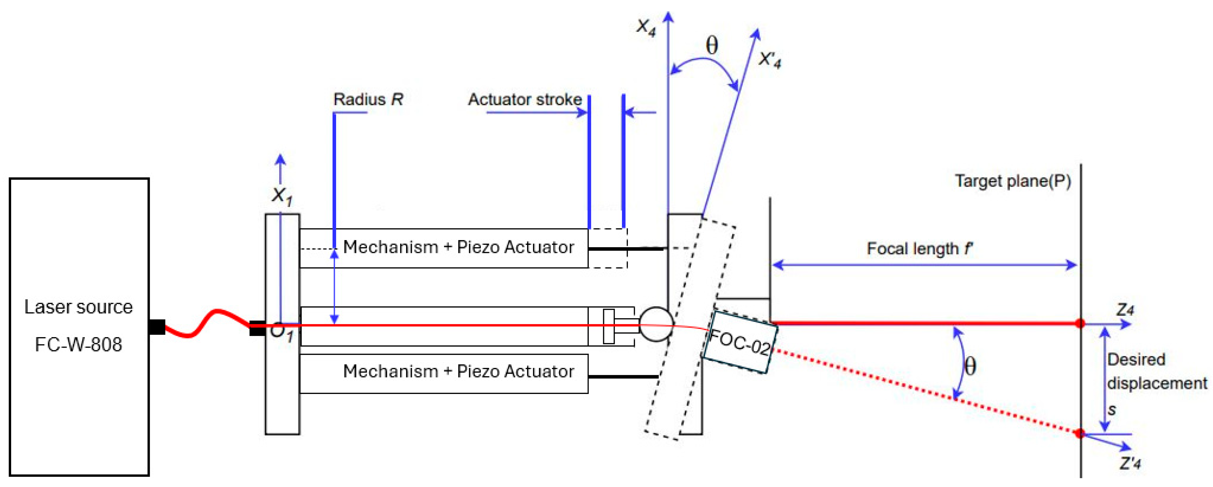
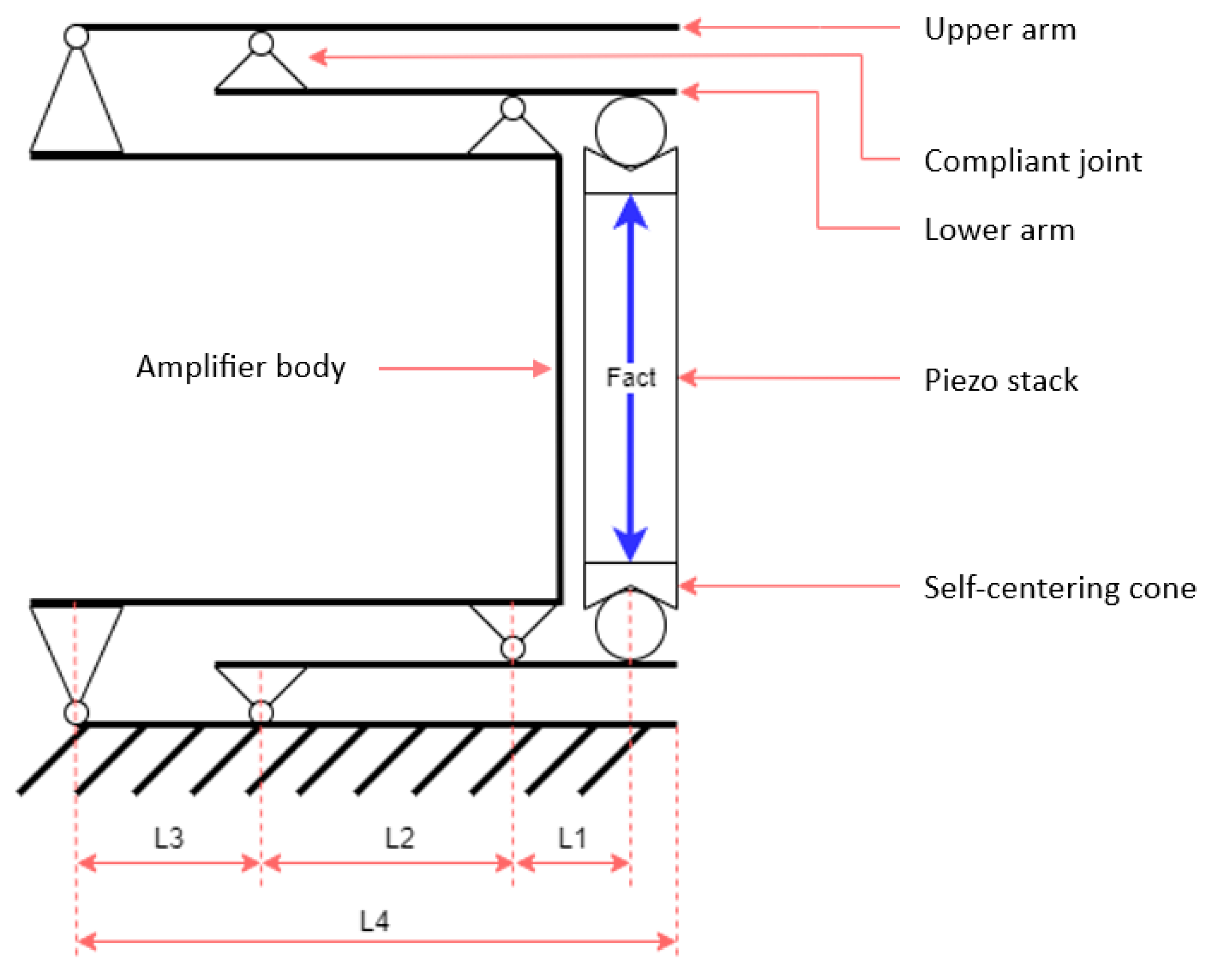
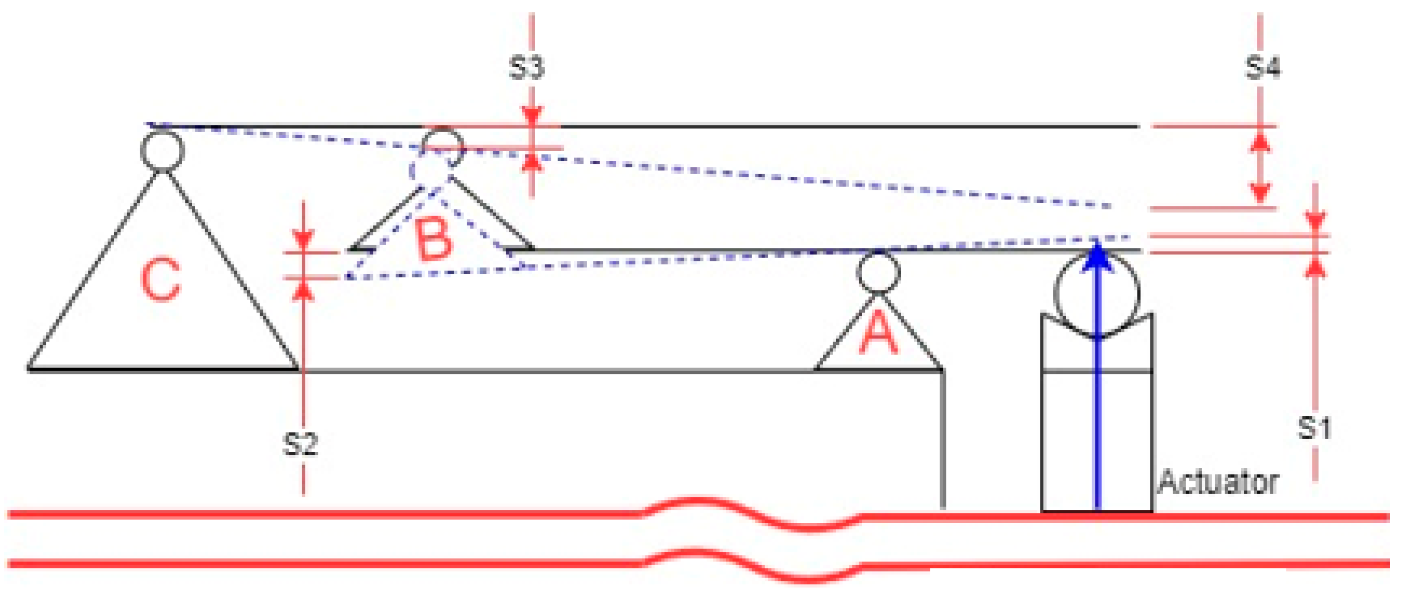
2.3. Schematics of the Mechanical Amplifier

The accuracy of the mechanical amplification mechanisms depends on certain characteristics, including the manufacturing technology, the processed material, the amount of play between the moving parts, and the dead stroke when changing the direction of travel. To properly address these design issues, the following design criteria were imposed: a minimum amplification ratio equal to 5:1 (while the available piezo actuator P-010.20 has a 30 μm free stroke); the type of available raw material; a reduced mechanical play between the moving parts; no dead stroke; as little friction as possible; the possibility of self-centering the piezoelectric stack, in order to eliminate the mechanical bending stress; the available manufacturing technology.
The schematic diagram that shows the solution chosen for the development of the amplification mechanism is presented in Figure 5. Two self-centering caps have been mounted on the piezoelectric actuator in order to eliminate the bending stress.
The symmetry of the upper half of the mechanical amplifier across the median plane (Figure 6) allows for an analysis that reduces the computational complexity while preserving the accuracy of a finite element analysis (FEA) simulation. This is due to the fact that the symmetry ensures that the mechanical behavior of the upper half mirrors the one of the lower halves, when they are placed under identical loading conditions. The piezoelectric actuator changes its length by applying a control voltage. Therefore, it performs the first stage of amplification with a ratio L2/L1. Similarly, when the first arm is tilted, the second one is acted upon and the second amplification is achieved, with a L4/L3 ratio. The total amplification ratio is the product of these two amplification stages.
Therefore, the S4 displacement is based on the product of the amplification ratios (S1 to S2 and S3 to S4) of the two amplification stages:
S 4 S 3 L 4 L 3 S 2 L 4 L 3 S 1 L 2 L 1 L 4 L 3 .

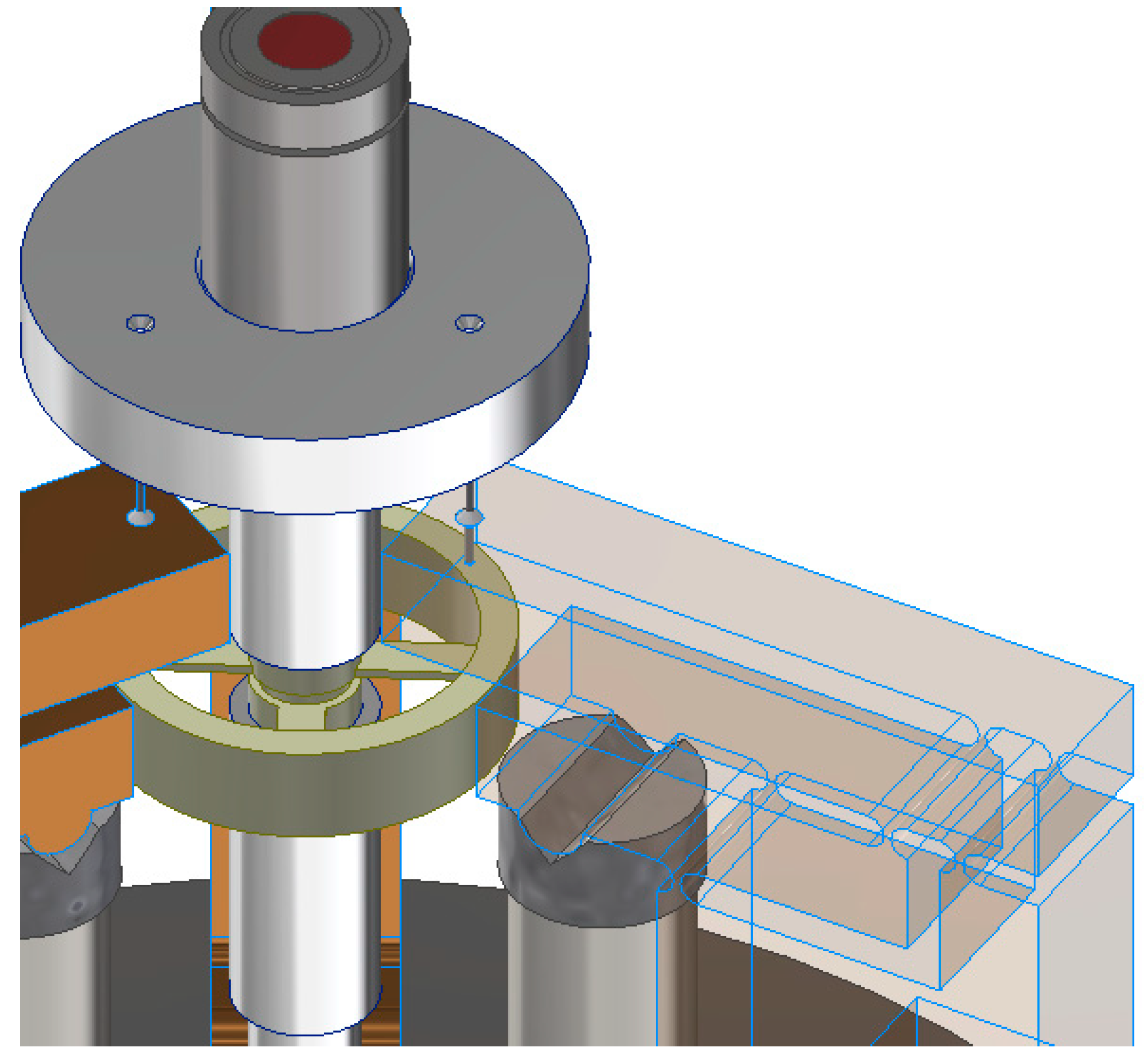
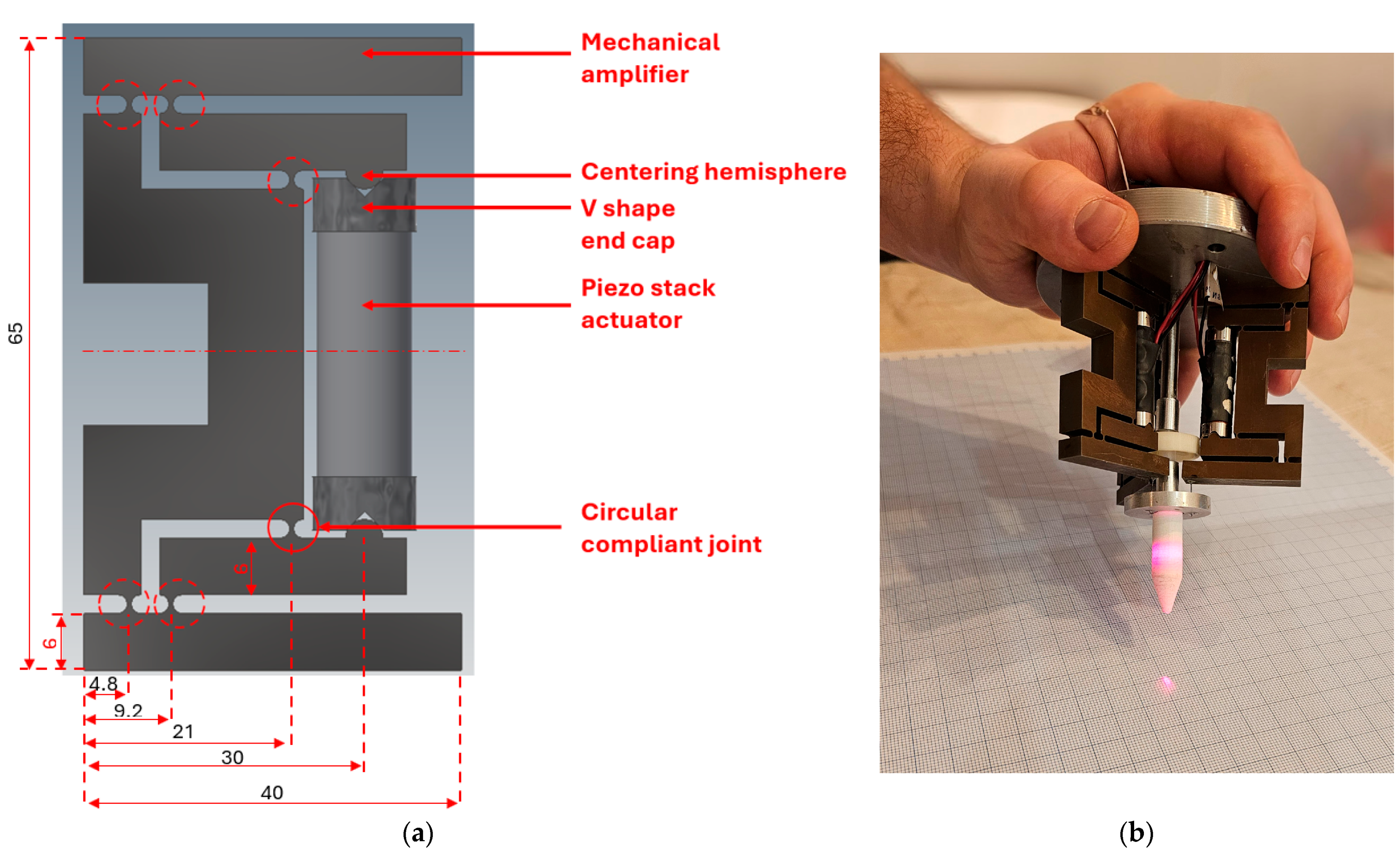
2.4. Three-Dimensional Model of the Mechanical Amplifier

The amplification device was designed using the 3D modeling and design software Inventor 2019 (Autodesk Inc., San Francisco, CA, USA). Figure 7a shows the amplification device with the piezoelectric actuator installed, presenting its actual dimensions. The device has been designed in order to follow the amplification logic presented in Figure 5. This means that it fits a P-010.20 piezo stack and is as small as possible. Figure 7b presents the entire designed and manufactured system, as a proof-of-concept (as future work has been pointed out for its miniaturization in order to make it appropriate for being handled by surgeons).
Two caps were designed and manufactured to secure the P-010.20 piezoelectric stack. Each of them features a V-shaped slot for self-centering on the amplification device via two semi-cylindrical areas. These areas serve several purposes: to ensure proper self-centering, to reduce the bending stress experienced by the piezoelectric stack, and to minimize the friction between the stack and the amplification device.

3. Experimental Validation of the Mechanical Amplifier

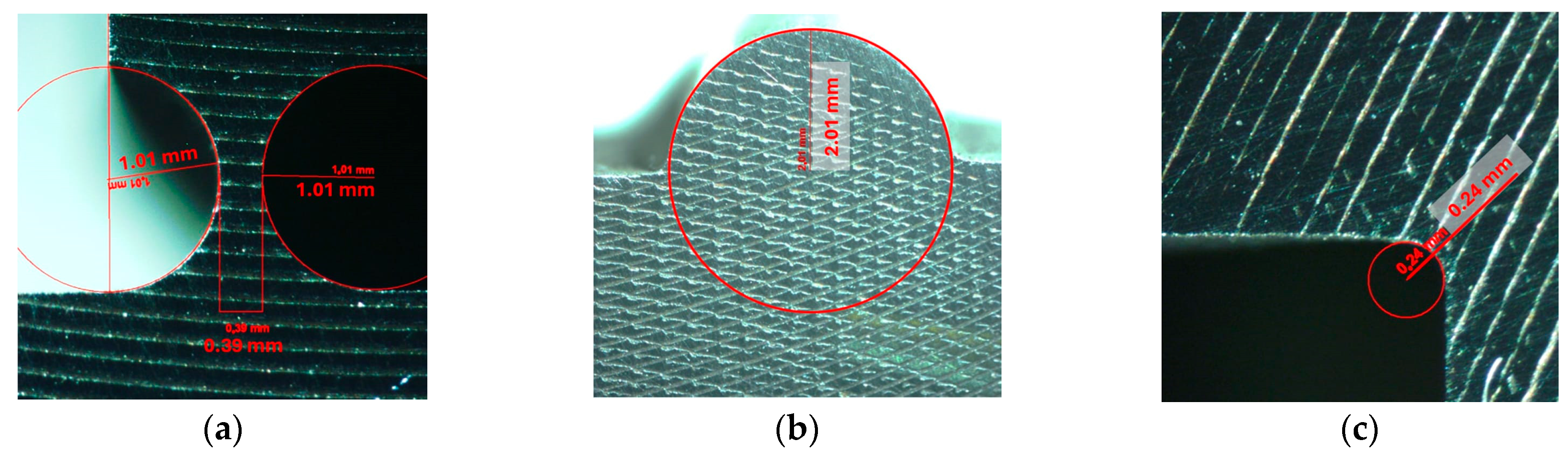
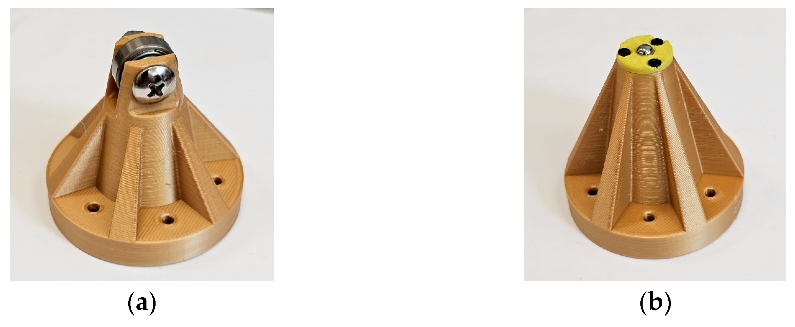
3.1. Manufacturing of the Mechanical Amplifier

Following the theoretical design and modeling of the mechanical amplification mechanism, its manufacturing was carried out at the National Research and Development Institute for Electrical Engineering ICPE-CA in Bucharest. The Wire Electrical Discharge Machining (WEDM) process was performed using a Smart Dem 320 A machine (Knuth, Königsberg, Germany). The WEDM uses a metallic wire to cut or shape a workpiece (that is often a conductive material) with a thin electrode wire that follows a precisely programmed path. In our case, the diameter of the chosen electrode was 0.4 mm. The developed 3D model presented in the previous subsection was utilized in order to obtain the necessary parts. Four mechanical amplifiers were fabricated as a single stack in order to ensure a uniform geometry across all units. Following this fabrication, a slicing operation was carried out in order to separate the individual amplifiers. Thus, each required component was obtained.
The mechanical properties of the utilized steel were determined experimentally using the nanoindentation method. The dedicated tool was a Vickers FM 700 Microhardness Tester (Future-Tech Corp. FM-700, Tokyo, Japan), while the Oliver and Pharr calculation method was employed. The material properties have been introduced in the FEA (i.e., they were declared as parameters of a new material in the performed simulations), as presented in Figure A1 (Appendix A).
The manufacturing stage was followed by the metrological inspection of the components in order to assess eventual deviations from their intended geometry (Figure 8). All the components were examined using a Zeiss Stemi2000-C microscope, equipped with an Axiocam Icc 1 video camera and a Zeiss 038-05436 tunable light source (ZEISS AG, Oberkochen, Germany). In order to measure the geometry of the components, the image analysis was conducted using the AxioVision software 4.8, which is associated with the above video camera (and manufacturer).
Upon completing the geometric verification of the parts, the cut components exhibited dimensional deviations with a maximum error of 0.01 mm. This corresponds to a deviation of up to 3% from the nominal dimensions. All spherical joints, as well as the fillet radius in the right-angle areas, were carefully inspected. The most significant measurements are illustrated in Figure 9. All four mechanical amplifiers were verified, thus confirming that the geometric deviations from the designed model were within the 0.01 mm tolerance. The next step involved conducting a static analysis of the mechanical components.

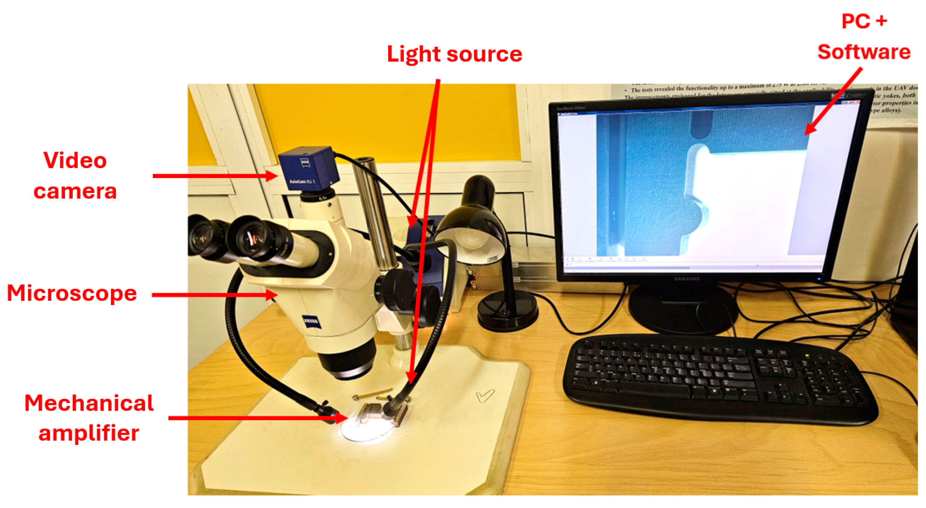
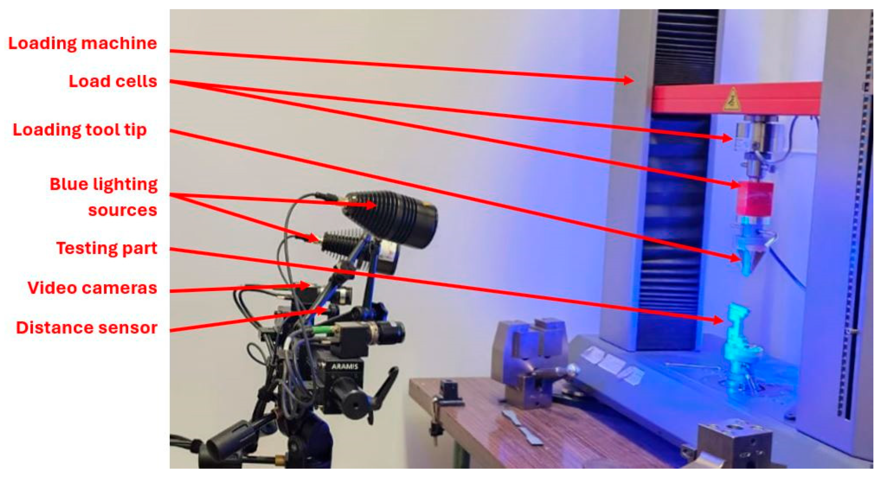
3.2. Setup for the Experimental Static Analysis

Two experimental tests were performed and are presented in the following. The first test was for half of the mechanism. The scope was to determine the amplification ratio for half of the amplifier. The second test was performed with the scope to validate the 3D model for the entire mechanism and thus, to determine the error between the physical and theoretical models.
In order to validate the amplification performance of the mechanism, an in-house developed experimental setup was employed (Figure 10). It integrates two testing systems: the Zwick-Roell Z010 testing machine (ZwickRoell, Ulm, Germany) with two 10 kN and 5 kN load cells using the HBM MGC AB 12 Amplifier (Hottinger Brüel & Kjær, Darmstadt, Germany), along with the ARAMIS 12MP camera measuring system (ZEISS AG, Oberkochen, Germany), equipped with an appropriate blue lighting system.
The testing procedure involved placing the sample in the lower grip of the Zwick Roell loading machine on a custom support specifically designed for the tested part. A rapid prototyping technique was utilized to develop this support.
The loading machine enables a controlled displacement with micrometric precision of the upper grip, where compression tools (that were specially designed for this test) were mounted. In series with these compression tools (mounted on the upper grip), load cells were integrated to measure the applied force. The upper grip moves downward in a controlled manner, and the machine records the force applied throughout the test.
In order to enhance the measurement accuracy and map the deformation field of the tested component, the Aramis video camera system was integrated in parallel to the setup described above. This Aramis system captures video frames during the deformation process; based on the analysis area, it determines deformations at specific points of interest.
The method is based on Digital Image Correlation (DIC), which primarily measures in-plane strains on the X and Y directions. However, with a 3D stereo-DIC setup, it is also possible to capture out-of-plane deformations and strains (i.e., in the Z direction). Therefore, it provides a comprehensive evaluation of the mechanical behavior of the sample. An evaluation using the Aramis camera systems must follow the following steps:
(i)
The setup of the 3D system requires two cameras that are positioned at different angles to capture stereoscopic images of the speckle pattern on the specimen. These cameras create a 3D reconstruction of the surface using triangulation.
(ii)
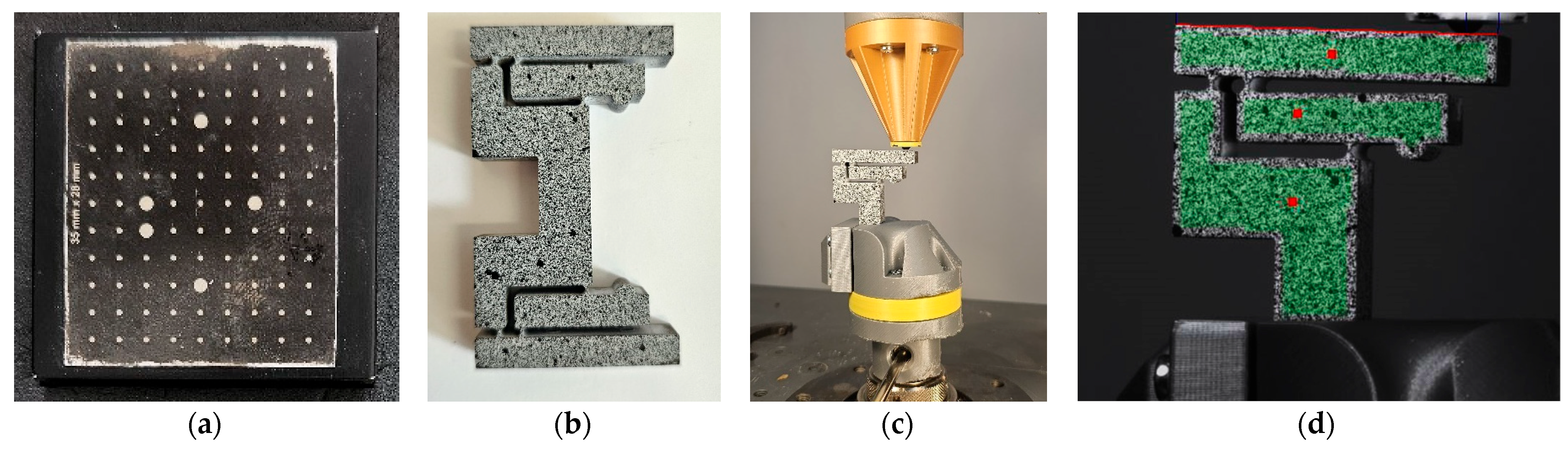
A precise calibration process using a known pattern, such as the checkerboard presented in Figure 11a. This phase is essential to determine the orientation of the camera and the spatial relationships. The calibration defines the transformation from 2D image coordinates to 3D world coordinates.
(iii)
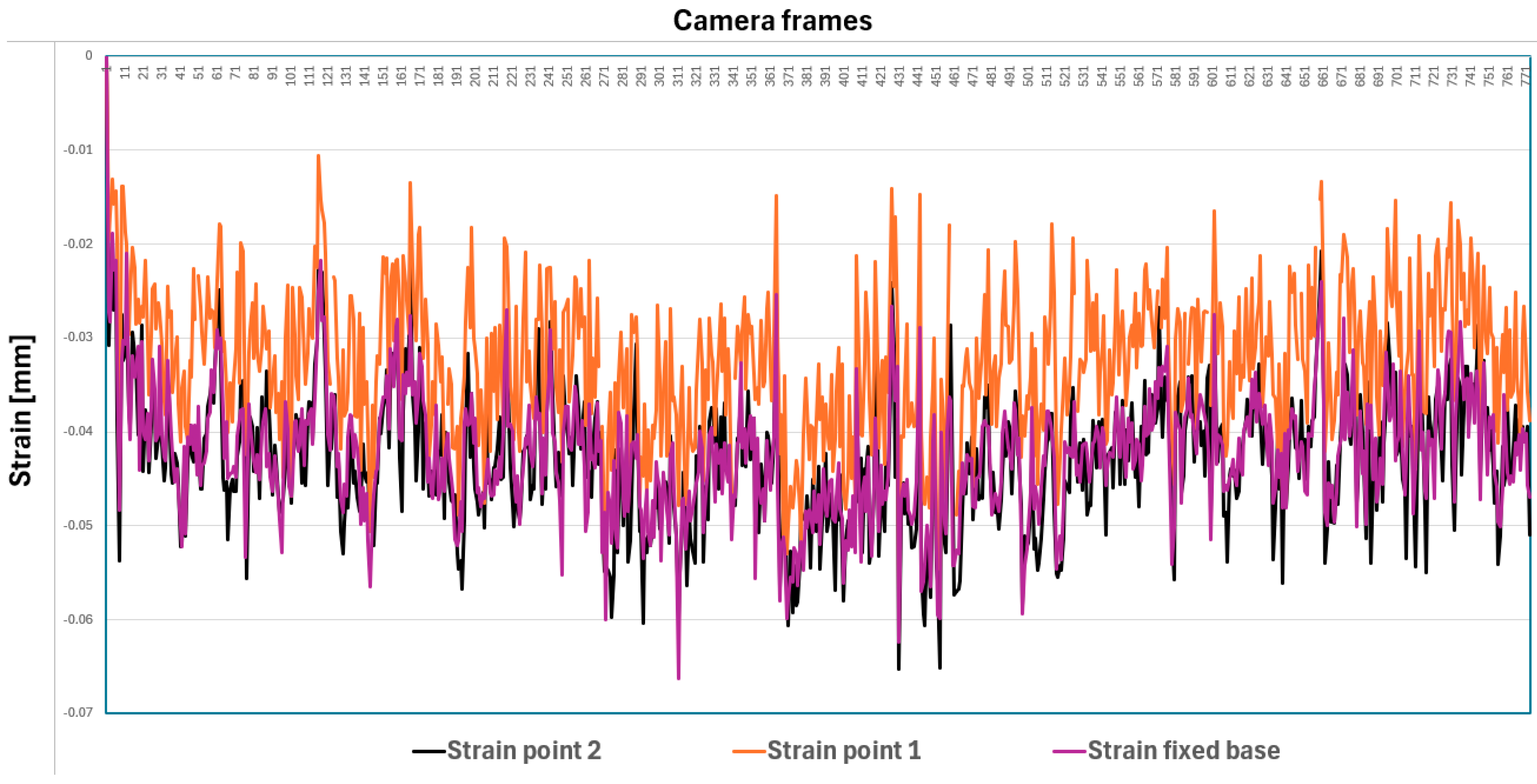
Speckle pattern tracking. The specimen is coated with a random speckle pattern, as shown in Figure 11b. As the sample is deformed, the Aramis DIC Zeiss Correlate software tracks the movement of these speckles in both images. The displacement fields are calculated in 3D (i.e., along the coordinates X, Y, and Z).
(iv)
Calculus of the strain. The strain is derived from the gradients of the displacement field. In practice, because the DIC measures surface data, the Z-strain often refers to out-of-plane surface deformation gradients rather than through-thickness strain.
(v)
Data analysis with ZEISS Correlate, where one can visualize displacement and strain components, including out-of-plane (i.e., along the Z axis) deformations.
The testing phases that are required in order to obtain accurate results imply the same constraints as in the FEA simulation, as shown in Figure 11c. The measurement area is constrained by the Aramis DIC Zeiss Correlate software software—Figure 11d. The actual compression test is conducted in order to obtain the deformation results by ensuring the necessary time synchronization between the measuring instruments.

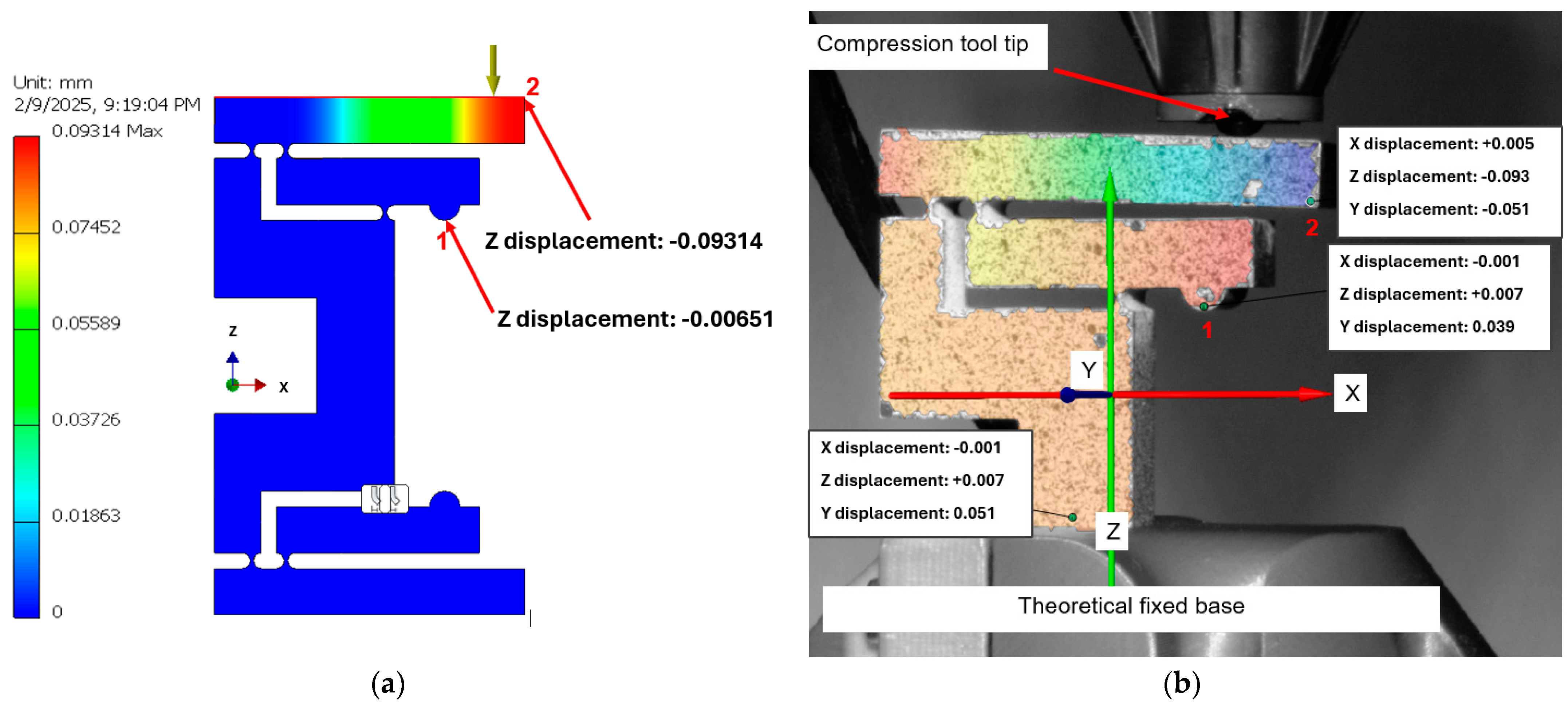
3.3. Comparison of the Experimental and FEA Results

The area where the piezoelectric actuator should operate cannot be subjected to external loading because of geometric constraints. Therefore, an inverted testing method has been implemented. This approach involves applying a variable force from the output point of the mechanical amplifier, specifically from the upper arm toward the lower arm.
The aim of the test has been to correlate its results with the FEA model of the amplification mechanism. Thus, the scope is to determine the force–deformation relationship, as well as, subsequently, the equivalent stiffness of the structure. Attempts to apply a force between the two inner arms to simulate the action of a piezo stack actuator have faced two challenges related to the geometry of the testing part, which interfered with the mechanical amplifier.
First, employing a U-shaped test probe for symmetric loading (one U-shape per arm) blocked the view of the 3D Aramis camera system, and therefore the measurements. Second, when using L-shaped test parts for the inner arms, it has become necessary to design an optimized geometry that could provide a stiffness that is at least 10 times higher than that of the tested mechanism, while maintaining an optimal FOV for the 3D camera system. For the entire assembly (consisting of mechanism plus piezo stack), it was not possible to obtain a force–displacement characteristic. Therefore, we determined only the amplification ratio, which has remained consistent with our experimental test results. Finally, the compliant mechanical amplifier performs similarly for both upper loading on the upper arm and for inner loading on the inner arm.
Considering how the testing is performed in real-life conditions, the same conditions were applied in the FEA environment in order to ensure a correct and consistent analysis. An important factor for this has been the exact position of the applied force in the experimental test. This position was measured based on the video footage captured by one of the cameras and was determined to be equal to 36 mm. The conducted FEA simulation utilized the Inventor software (Autodesk, San Francisco, CA, USA). It replicated real-life conditions and implied an applied force that matches the one measured experimentally using the load cells of the machine (i.e., 12 N). The obtained FEA results are presented in parallel to the 12MP Camera Aramis system experimental results in Figure 12. The results for the two considered key points have been closely aligned. Thus, in Figure 12 one observes that at the theoretical input of the mechanical amplifier (i.e., point 2), the obtained displacement is equal to −6.51 μm in the FEA and −7 μm in the experiments, while at the tip of the upper arm, the displacement was −93.14 μm in the FEA and −93 μm in the experiments. Only vertical displacements have been considered, as this is the primary parameter of interest for this application.
Therefore, considering the maximum applied force, the error for the first test (i.e., using half of the amplifier) is 7.52% at the considered point 1 and less than 1% at point 2 of the amplifier. This test confirms the good correlation between the physically manufactured part and the 3D model. It ensured that the actual amplification ratio obtained was 14.3:1 for half of the amplifier. These results are also important for future correlations to different mathematical models.
Taking a closer look at the Y axis, there is a significant displacement that should not exist. We must highlight that the tests have been conducted on the same sample, using identical fixing and loading tools, as well as the same loading machine in order to ensure consistency. Also, the camera system acquisition has been initiated after the preload procedure.
Supplementary, in order to ensure the accuracy of the 3D camera system, an inductive displacement transducer Mahr P2004 (Mahr Gmbh, Göttingen, Germany) was integrated in parallel into the setup. This transducer was connected to the Mahr Milliron 1202D signal measurement and conditioning system (Mahr Gmbh, Göttingen, Germany). Thus, it offered a measurement accuracy of 0.01 μm within a range of ±20 µm. The highest value obtained for the Y-axis displacement of the part was 2.26 μm when measured at the fixing base. This means that the system is rigid enough to perform the test.
Another measurement was performed at the upper arm level of the tested part. The Y-axis displacement increased to 5.06 µm, which means that there is a supplemental 3 μm deviation. The main causes of these displacements are: (i) residual misalignments in the assembly that resulted in unintended lateral forces during compression; (ii) a low preload force; (iii) structural asymmetries in the compliant mechanism introduced minor deviations during actuation (specifically, the circular joints of the compliant mechanism were not perfectly parallel, thus leading to a small deviation); (iv) regarding the Aramis system, the Y-strain measurement is generally less sensitive compared to an in-plane strain because of the limits of the camera resolution and of because of perspective errors. Regarding the latter aspect, because DIC captures surface deformation, the Y-axis strain does not accurately represent internal material behavior unless it is supplemented with additional measurement methods, such as the inductive transducer utilized in this case. Additionally, out-of-plane measurements are inherently more prone to noise, especially where complex geometries (such as one of the developed systems) are involved. Despite these potential shortcomings, after repeating the test, the results remained consistent, thus confirming the validity of the experimental setup.
The mean values of the Y-axis displacements are quite stable (i.e., around 40 μm), and they have an offset caused by the preload condition (Figure 13). Because of the measurement approach (i.e., using the Aramis 12 MP camera system), the Y-axis values are noisy, therefore they are not considered further on for the discussion of results. However, the X and Z in-plane values are in the ±1 μm precision class, considering the inductive transducer as a reference measuring instrument.
The next step in validating the entire FEA model involved a comprehensive test of the mechanical amplifier. Two compression tests were performed, using both a ball and a roller terminal (Figure 14). The results of these tests are shown in Figure 15. It can be observed that when the part is deformed using the roller terminal, a transverse displacement occurs along the Y-axis. This displacement should not be present if the contact line of the roller was in the same plane as the compression surface of the upper arm. However, this misalignment exists, and it induces a transverse displacement of the part of approximately 1 mm. This is unacceptable for performing comparisons to the FEA. For this reason, only the ball compression test was considered for comparative analysis, as its contact with the compression surface can be considered punctiform, ensuring a more localized and precise interaction.
The errors obtained (for vertical displacements only) with the same applied force (i.e., 12 N), compared to the FEA results shown in Figure 16 under the same external conditions, are presented in Table 1.
It can be concluded that the physically developed amplification mechanism is consistent with the 3D modeled and FEA version, despite a maximum absolute error of 7.52%. A potential source of error between the two systems is the sensitivity of the load cell. Given the measuring range of 0 to 5 kN for the lower load cell, the measured value of 12 N may have an error of ±0.5 N, which falls within the 0.01% tolerance of the amplifier. Another cause for this error could be the manufacturing limitations regarding the right edge areas and surface parallelism that may influence the mechanism trajectory. Despite this, we can conclude that the experimental test confirms the good correlation between the models and supports moving forward with the product development.
One must point out that we have chosen experimental tests instead of simulations using COMSOL Multiphysics platform (COMSOL, Inc., Burlington, MA, USA), for example, because for simulations, it depends a lot on how the contact area in COMSOL is declared between the V-shaped cap of the piezo stack and the mechanical amplifier. The sliding between the hemisphere and the V-shaped cap must be modeled; the prestressing of the stack must be considered as well. This is the reason why, for such ascertainments, a compression (experimental) testing method is safer in order to obtain error-free results.

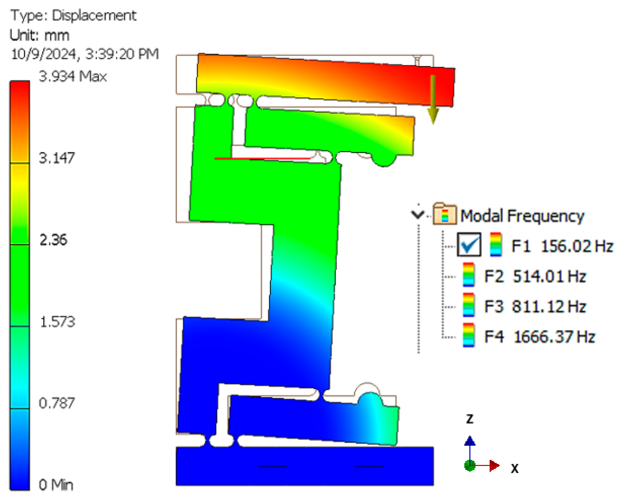
3.4. Preliminary Dynamic Simulations

The final step is to analyze the dynamics of the entire amplifier in order to determine its resonant frequencies. They must be outside the application’s range of interest (i.e., much higher than 15 Hz) in order for the structure to fulfill its purpose. Figure 17 illustrates the resonance frequencies of the mechanical amplifier, with its fixed constraint positioned at the lower section. This constraint corresponds to the attachment point intended for a future fixed platform, which is designed to incorporate three such mechanisms. The first frequency occurs at 156.02 Hz, which is well above the frequency range of the application, thus confirming the capability of the structure to perform its scope.
One must observe that a complete dynamic model includes the impedances of the piezo actuator, the compliant mechanism, and the upper section of the device. The resonance frequency of the piezo actuator is specified in the technical data sheet at approximately 35 kHz. According to the piezo actuator theory, for materials with significant damping, the system behaves purely as a compliance up to at least 50% of the resonance frequency. If the damping is minimal, this behavior extends up to 70% of the resonance frequency.
The simulation shown in Figure 17 indicates a first resonance frequency of 156 Hz. Because the utilized material is steel with a low internal damping, the mechanism could be operated up to a frequency of 70–80 Hz, assuming it behaves purely as a compliance. However, our primary area of interest is limited to a maximum of 20 Hz, specifically for tremor compensation.
We must point out that these results are currently based solely on software simulations. Therefore, they require experimental validation, which is a primary focus of future research. Additionally, the differences between the dynamic response of the single mechanical amplifier and the combined dynamic response of the actuation subsystem (including the mechanical amplifier, end caps, and piezoelectric stack) must be thoroughly investigated, as well. However, the above simulation confirms that the resonant frequency is well above the required frequency band. Finally, compensation tests are necessary in order to evaluate the performance of the proposed solution.

3.5. Mechanical Subassembly Testing

A comprehensive mathematical model of the assembly must account for the elasticity, inertia, and damping of the piezoelectric actuator and its associated compliant mechanism. Also, the elasticity and inertia of the spherical joint (metal wire) and of the central compliant joint must be considered, as well. As demonstrated in Section 2, the simplified kinematic model of the device exhibits nonlinearity. The inclusion of these additional elasticities is expected to result in a highly complex global mathematical model. This makes developing an efficient control law a challenge.
To ensure a robust demonstration of the principle, a strategic decision was made to oversize the actuators relative to the stiffness of the spherical and central joints. This choice is strongly justified by the following key observations: (i) the maximum blocking force of the actuators, as specified in their catalog, is equal to 2000 N; (ii) the expected force at the actuator output is equal to 1000 N, which results in approximately 100 N at the amplifier output; (iii) the stiffness of the upper section, consisting of the central joint, mobile platform, and spherical joints, is extremely low, which means that the force required for the desired displacement is significantly lower than the force generated by the actuator. This assumption is going to be validated further on through the final FEA testing.
As a result, it can be confidently stated that the actuator and the compliant mechanism operate with an optimal load, allowing for neglecting the spherical and central joints in the primary analysis.
However, in order to have rigorous results, a holistic approach to the stiffness of the system is also proposed. Thus, in order to further refine the stiffness characterization, another experimental test is conducted with the piezo actuator mounted on the amplifier. This assessment of the rigidity of the entire system was made using a motion analysis test that was conducted on the actuation subassembly with the piezoelectric actuator mounted on the mechanical amplifier. This test is important for determining both the maximum stroke of the actuator and the trajectory of the key points of interest, labeled as 1 and 2 in Figure 16. These points must be utilized further in the global system simulation to evaluate the mechanical stress occurring at the spherical joint.
Also, in order to verify the measurement accuracy, sequential measurements were performed using the inductive displacement transducer across all three spatial directions.
The piezoelectric actuator was controlled using a ramped voltage signal of 0-10-0 V, with a variation rate of 0.1 V/s. The control signal was generated using a MyRIO-1950 development board, with the control program implemented in LabVIEW. Then, the signal was amplified using an E472.20 high-voltage amplifier (100:1 ratio, 1000 V, 500 W) in order to drive the actuator.
The Aramis video capture system has limitations in terms of a restricted area of analysis. Also, in order to perform analyses on the entire system, this should be disassembled, prepared, and reassembled for testing (including pattern painting for tracking—Figure 11a). To avoid these issues, the test was conducted on one subassembly only. Also, one must point out that the 3 DOF system was assembled using cyanoacrylate adhesive in order to maintain its structural integrity; therefore, it would have been impossible to disassemble it without producing significant damage.
It is worth mentioning that constructive limitations of the utilized load measuring machine include the requirement to maintain collinear measurement samples while the part is rotating. Therefore, it is not possible to determine directly the force–deformation characteristic for the entire system. Moreover, inserting a traction tool between points 1 and 2 would introduce a bending force on the load cell, rendering the force measurements unreliable and unusable. This unintended loading condition would compromise the accuracy of the recorded force values, affecting the overall validity of the experimental results.
The results of the subassembly testing are presented in Figure 18.
The DIC analysis provides a displacement map of the tested structure in the Z-axis direction, utilizing a color-coded scale ranging from 0 mm (red) to −0.228 mm (blue). Point 5 was included to ensure the correlation between the inductive transducer readings and the values obtained using the Aramis software.
The measurement accuracy of the Aramis software in the XZ plane is ±1 μm, with the Mahr P2004 transducer utilized as the reference instrument. However, for the Y-axis direction, the recorded values are in the 30 ± 6 μm range. This deviates from the inductive transducer measurements, for which a maximum displacement of 5.02 μm was observed. The discrepancy is due to the previously discussed limitations. Nonetheless, Y-axis displacements are not a primary concern, as they cannot be considered reliable under these testing conditions. Thus, the key results of this test are as follows:
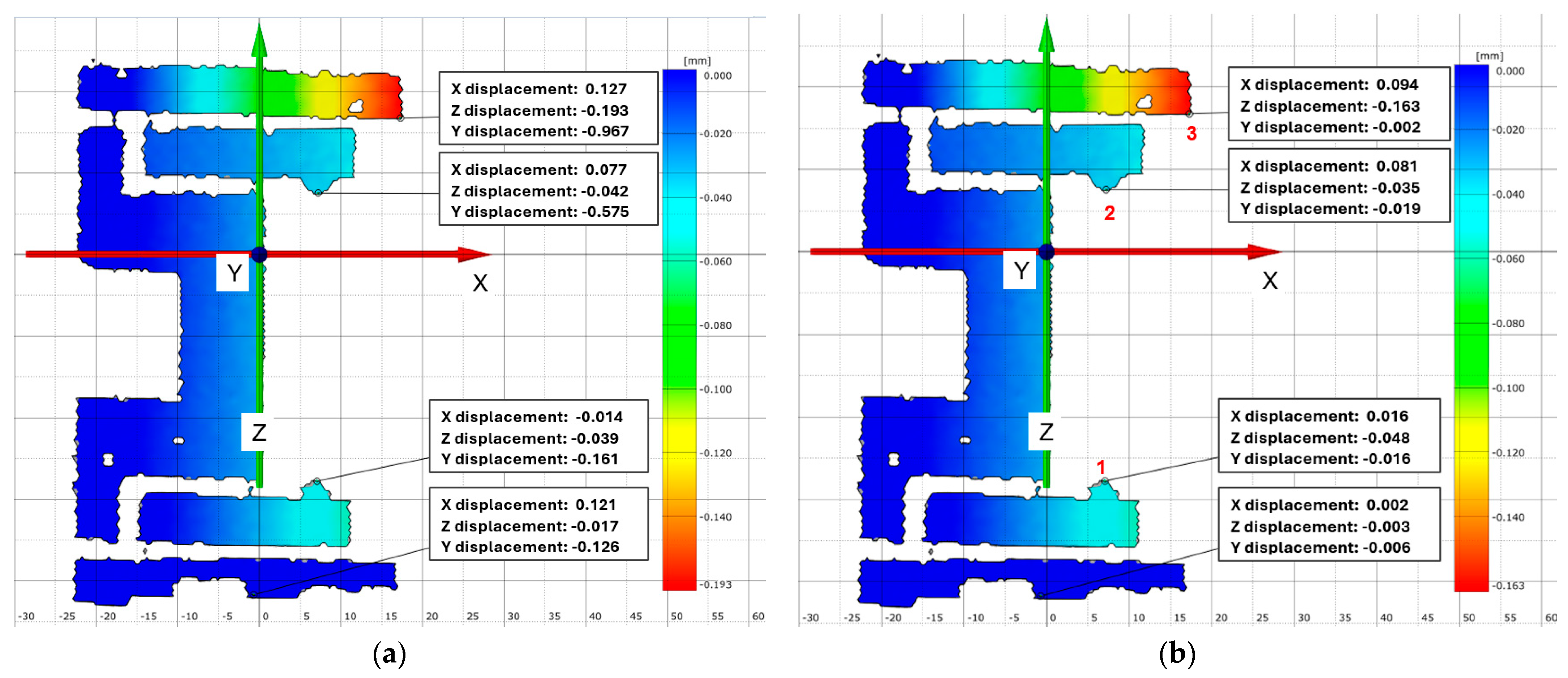
  • Point 3 (upper arm tip) shows an X displacement of 0.159 mm and a Z displacement of −0.218 mm.
  • Point 2 (middle arm) shows an X displacement of 0.145 mm and a Z displacement of −0.068 mm.
  • Point 1 (lower arm) shows an X displacement of 0.035 mm and a Z displacement of −0.088 mm.
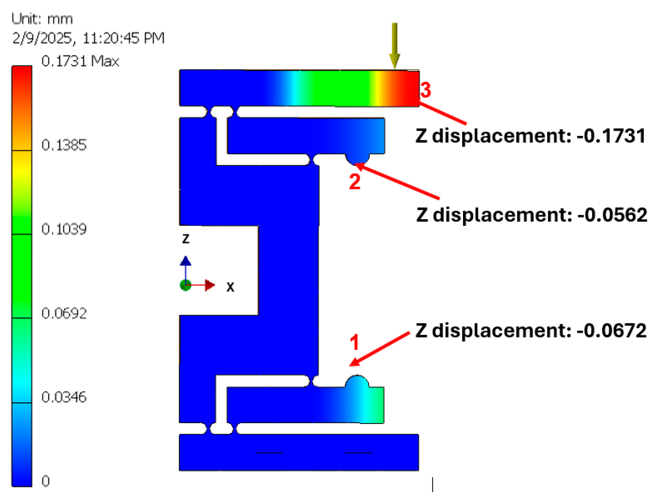
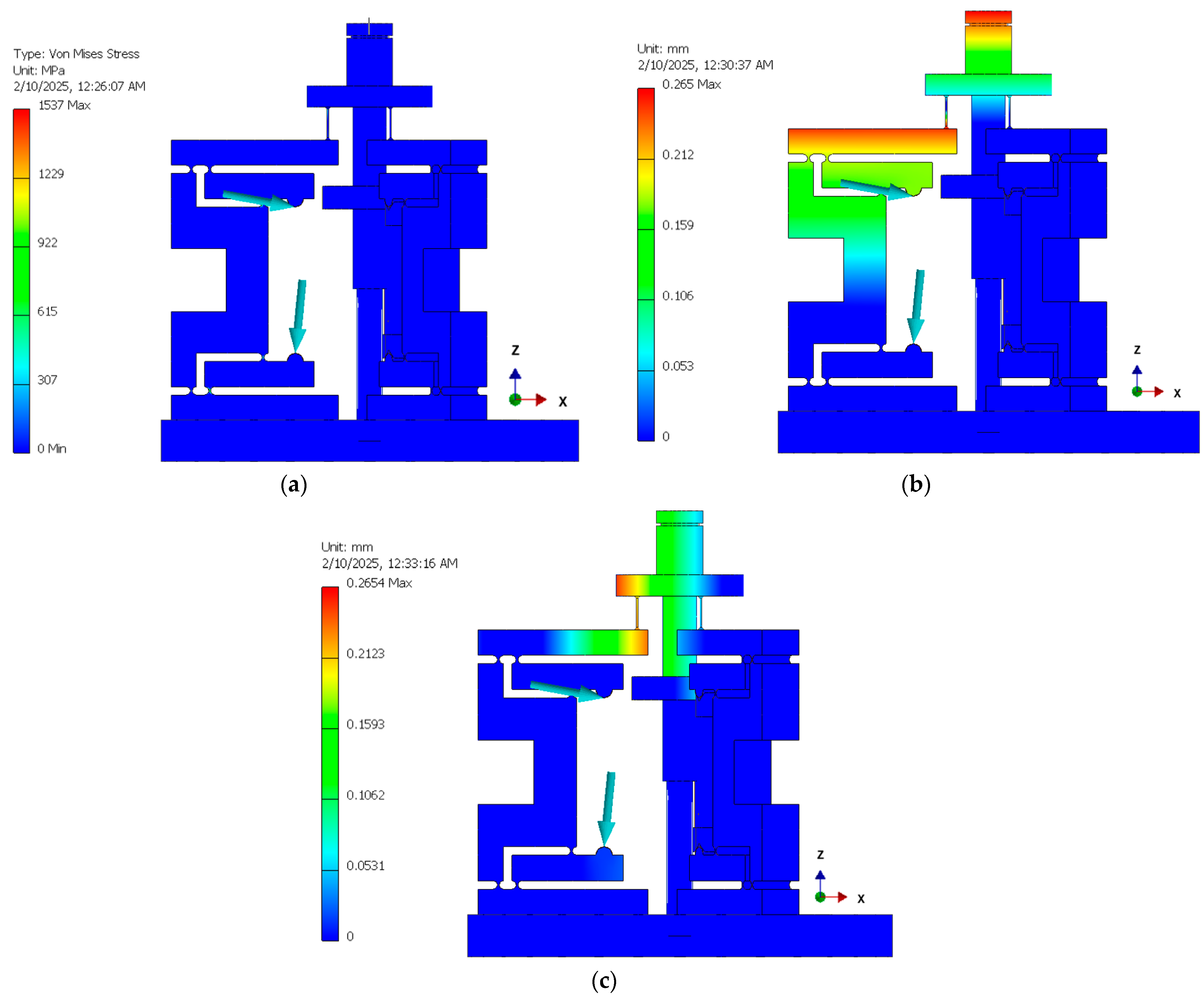
3.6. Three DOF FEA

The determined positions of points 1 and 2, as well as the maximum stroke of the actuator, can be utilized for the FEA of the entire system. The following limitations and assumptions were considered throughout the FEA simulation:
  • Passive piezoelectric actuators (that were not involved in the actuation) were replaced with solid steel blocks in order to simplify the model.
  • The actuator responsible for the system displacement was removed, and previously determined dimensional constraints were applied to calculate the reaction forces at the corresponding points.
  • The diode component was modeled as an aluminum block to represent its structural impact.
The materials selected for the various components are as follows: central joint—ABS M30; mobile platform, fixed platform, central road, and terminal caps of the piezoelectric stack—Aluminum 5083; spherical joints—MP35N (Cobalt–Nickel–Chromium–Molybdenum alloy), which is a specialized alloy commonly utilized for compliant structures in medical applications.
The length of the spherical joint (i.e., the distance between the mobile platform and the upper arms of the amplifiers) was set to 8 mm, which was chosen optimally in order to reduce mechanical stress. The wire diameter of 0.4 mm has also been chosen optimally. The simulation results are presented in Figure 19.
One can observe that the maximum stress occurs at the spherical joint level, with a magnitude of 1537 MPa. This value remains approximately 20% below the material’s maximum limit of 1900 MPa, which can go up to 2200 MPa when the material is aged. The maximum mechanical stress at the central joint is around 5 MPa, which is also well below the admitted value of 30 MPa.
The maximum X displacement is observed at the diode level, where it is equal to 0.265 mm, while the maximum Y displacement is equal to 0.1593 mm. By considering the 35 mm distance from the central joint to the diode tip, the resulting rotation angle is calculated to be 0.43°.
The reaction forces at the geometrical constraint points (i.e., where the piezo actuator is expected to be positioned) were extracted from the FEA simulation and are presented in Figure 20.
The total reaction force is approximately 1000 N, which aligns well with the expected values. It confirms that the piezo actuator is capable of deforming the entire structure and achieving the desired rotation angle. The reaction torque can be neglected because of the self-centering end cups, which minimize this torque, keeping it as close as possible to zero at the piezo stack level.

4. Conclusions

We presented the design, fabrication, and multiple testing stages of a specialized platform that is aimed at compensating for the hand tremor in medical laser equipment. The key development aspects have included the design of a Stewart-type platform tailored for laser surgery, the design and integration of a mechanical amplifier within the macro-scale platform, the fabrication and visual inspection of the amplifier, the static FEA and experimental validation, as well as a dynamical FEA simulation of the amplifier. The results of this study have been promising; therefore, one may consider that they provide a solid foundation for further development, including miniaturization and optimization of the system. In this respect we must highlight that the proposed device serves as a proof-of-concept and has not been designed for immediate surgical applications. Future research and development efforts are focused both on miniaturization and on transitioning the device toward practical, real-world applications.
A contribution of this work lies in the development of a novel mechanical amplifier model, which enhances the performance of the system by optimizing the force transmission within the compliant mechanism. Flexible wires have been utilized, thus simplifying the assembly process and introducing a pseudo-spherical joint. Additionally, a key innovation lies in the introduction of a hybrid experimental testing approach that combines a high-resolution optical 3D measurement system with a material testing machine. This dual-method approach enables precise validation of the 3D amplifier model, material behavior, and static performance of the compliant mechanism, while also providing preliminary insights into its dynamic behavior and useful frequency range.
To advance toward practical implementation, ongoing and future work on this proof-of-concept prototype includes: (i) a flexural analysis of the entire amplifier body under the applied actuator forces (including the elastic joint); (ii) the calculus of the stiffness and compliance for the amplifier; (iii) development of a flexural/mechanical model of the entire elastic structure, including an evaluation of stiffness, compliance, and natural frequencies; (iv) dynamic experiments to assess the mechanical amplifier, actuating subsystem, and overall system response; and (v) the ascertainment of the vibration compensation capabilities in its intended function as a laser scalpel.
Overall, one may say that the results of this study demonstrate the feasibility of the proposed design and its potential for future applications, in particular in medical robotics and precision surgical tools.

Author Contributions

Conceptualization and methodology, E.I.N. and D.C.C.; finite element analysis (FEA), E.I.N.; experimental systems and investigations, E.I.N. and D.A.A.; validation, D.C.C. and V.-F.D.; formal analysis, E.I.N. and D.C.C.; resources, E.I.N., D.C.C., D.A.A. and V.-F.D.; data curation, E.I.N.; writing—original draft preparation, E.I.N. and V.-F.D.; writing—review and editing, D.C.C. and V.-F.D.; visualization, E.I.N., D.C.C. and V.-F.D.; supervision and project administration, D.C.C.; funding acquisition, E.I.N., D.C.C. and V.-F.D. All authors have read and agreed to the published version of the manuscript.

Funding

The research was supported by the Romanian IPCEI (Important Project of Common European Interest) on microelectronics, via Continental Automotive Romania and indirect partners (National University of Science and Technology Politehnica Bucharest and University Politehnica Timisoara). V.-F. Duma also acknowledges the support of the COST Action CA21159 (PhoBioS).

Institutional Review Board Statement

Not applicable.

Informed Consent Statement

Not applicable.

Data Availability Statement

Data supporting reported results can be obtained from the first author.

Acknowledgments

This paper is based on presentations prepared for the ‘2nd International Conference—Advances in 3OM–Opto-Mechatronics, Opto-Mechanics, and Optical Metrology’, 11–14 December 2023, Timisoara, Romania. We acknowledge the support of the National Research and Development Institute for Electrical Engineering ICPE-CA in Bucharest, Romania, for the manufacturing of the mechanical amplification mechanism of the developed device.

Conflicts of Interest

The authors declare no conflicts of interest.

Appendix A

Figure A1. Mechanical characteristics of the amplifier’s material determined from experimental investigations and considered for the FEA.
Applsci 15 03686 g0a1

References

  1. Bhatia, K.P.; Bain, P.; Bajaj, N.; Elble, R.J.; Hallett, M.; Louis, E.D.; Raethjen, J.; Stamelou, M.; Testa, C.M.; Deuschl, G.; et al. Consensus Statement on the Classification of Tremors. from the Task Force on Tremor of the International Parkinson and Movement Disorder Society. Mov. Disord. 2018, 33, 75–87. [Google Scholar] [CrossRef] [PubMed]
  2. Bain, P.A. Combined Clinical and Neurophysiological Approach to the Study of Patients with Tremor. J. Neurol. Neurosurg. Psychiatry 1993, 56, 839–844. [Google Scholar] [CrossRef] [PubMed]
  3. Ang, W.T.; Pradeep, P.K.; Riviere, C.N. Active Tremor Compensation in Microsurgery. In Proceedings of the 26th Annual International Conference of the IEEE Engineering in Medicine and Biology Society, San Francisco, CA, USA, 1–5 September 2004; Volume 3, pp. 2738–2741. [Google Scholar]
  4. Brown, W.J.; Buckland, E.L.; Izatt, J.A. Portable Optical Coherence Tomography (OCT) Devices and Related Systems. U.S. Patent Application 0081166, 2007. [Google Scholar]
  5. Erickson, S.J.; Godavarty, A. Hand-Held Based near-Infrared Optical Imaging Devices: A Review. Med. Eng. Phys. 2009, 31, 495–509. [Google Scholar] [CrossRef]
  6. Capitán-Vallvey, L.F.; Palma, A.J. Recent Developments in Handheld and Portable Optosensing—A Review. Anal. Chim. Acta 2011, 696, 27–46. [Google Scholar] [CrossRef]
  7. Demian, D.; Duma, V.-F.; Sinescu, C.; Negrutiu, M.L.; Cernat, R.; Topala, F.I.; Hutiu, G.; Bradu, A.; Podoleanu, A.G. Design and Testing of Prototype Handheld Scanning Probes for Optical Coherence Tomography. Proc. Inst. Mech. Eng. H 2014, 228, 743–753. [Google Scholar] [CrossRef]
  8. Monroy, G.L.; Won, J. Clinical Translation of Handheld Optical Coherence Tomography: Practical Considerations and Recent Advancements. J. Biomed. Opt. 2017, 22, 1–30. [Google Scholar] [CrossRef]
  9. Lu, C.D.; Kraus, M.F.; Potsaid, B.; Liu, J.J.; Choi, W.; Jayaraman, V.; Cable, A.E.; Hornegger, J.; Duker, J.S.; Fujimoto, J.G. Handheld Ultrahigh Speed Swept Source Optical Coherence Tomography Instrument Using a MEMS Scanning Mirror. Biomed. Opt. Express 2014, 5, 293. [Google Scholar] [CrossRef]
  10. Roizenblatt, M.; Edwards, T.; Gehlbach, P.L. Robot-Assisted Vitreoretinal Surgery: Current Perspectives. Robot. Surg. Res. Rev. 2018, 5, 1–11. [Google Scholar] [CrossRef]
  11. Ida, Y.; Sugita, N.; Ueta, T.; Tamaki, Y.; Tanimoto, K.; Mitsuishi, M. Microsurgical Robotic System for Vitreoretinal Surgery. Int. J. Comput. Assist. Radiol. Surg. 2012, 7, 27–34. [Google Scholar] [CrossRef]
  12. Rusch, M.; Hoffmann, G.; Wieker, H.; Bürger, M.; Kapahnke, S.; Berndt, R.; Rusch, R. Evaluation of the MMI Symani® Robotic Microsurgical System for Coronary-Bypass Anastomoses in a Cadaveric Porcine Model. J. Robot. Surg. 2024, 18, 168. [Google Scholar] [CrossRef]
  13. Kwoh, Y.S.; Hou, J.; Jonckheere, E.A.; Hayati, S.A. Robot with Improved Absolute Positioning Accuracy for CT Guided Stereotactic Brain Surgery. IEEE Trans. Biomed. Eng. 1988, 35, 153–160. [Google Scholar] [CrossRef]
  14. Taylor, R.; Jensen, P.; Whitcomb, L.; Barnes, A.; Kumar, R.; Stoianovici, D.; Gupta, P.; Wang, Z.; deJuan, E.; Kavoussi, L. A Steady-Hand Robotic System for Microsurgical Augmentation. In Proceedings of the Medical Image Computing and Computer-Assisted Intervention—MICCAI’99, Cambridge, UK, 19–22 September 1999; Springer: Berlin/Heidelberg, Germany, 1999; pp. 1031–1041. [Google Scholar] [CrossRef]
  15. Probst, P. A Review of the Role of Robotics in Surgery: To DaVinci and Beyond! Mo Med. 2023, 120, 389–396. [Google Scholar]
  16. Lanfranco, A.R.; Castellanos, A.E.; Desai, J.P.; Meyers, W.C. Robotic Surgery: A Current Perspective. Ann. Surg. 2004, 239, 14–21. [Google Scholar] [CrossRef]
  17. Veluvolu, K.C.; Ang, W.T. Estimation of Physiological Tremor from Accelerometers for Real-Time Applications. Sensors 2011, 11, 3020–3036. [Google Scholar] [CrossRef] [PubMed]
  18. Sandoval, R.; MacLachlan, R.A.; Oh, M.Y.; Riviere, C.N. Positioning Accuracy of Neurosurgeons. In Proceedings of the 29th Annual International Conference of the IEEE Engineering in Medicine and Biology Society, Lyon, France, 22–26 August 2007; pp. 206–209. [Google Scholar]
  19. Riviere, C.N.; Rader, R.S.; Khosla, P.K. Characteristics of Hand Motion of Eye Surgeons. In Proceedings of the 19th Annual International Conference of the IEEE Engineering in Medicine and Biology Society, Chicago, IL, USA, 30 October–2 November 1997; Volume 4, pp. 1690–1693. [Google Scholar]
  20. Lin, Z.; Deng, A.; Hou, N.; Gao, L.; Zhi, X. Advances in Targeted Retinal Photocoagulation in the Treatment of Diabetic Retinopathy. Front. Endocrinol. 2023, 14, 1108394. [Google Scholar] [CrossRef]
  21. Reddy, S.V.; Husain, D. Panretinal Photocoagulation: A Review of Complications. Semin. Ophthalmol. 2018, 33, 83–88. [Google Scholar] [CrossRef] [PubMed]
  22. Becker, B.C.; MacLachlan, R.A.; Lobes, L.A.; Riviere, C.N. Semiautomated Intraocular Laser Surgery Using Handheld Instruments. Lasers Surg. Med. 2010, 42, 264–273. [Google Scholar] [CrossRef]
  23. Channa, R.; Iordachita, I.; Handa, J.T. Robotic Eye Surgery. Retina 2017, 37, 1220–1228. [Google Scholar] [CrossRef]
  24. Olds, K.C.; Taylor, R.H. Steady Hand Micromanipulation Robot. U.S. Patent 8,911,429 B2, 2017. [Google Scholar]
  25. Becker, B.C.; Valdivieso, C.R.; Biswas, J.; Lobes, L.A.; Riviere, C.N. Active Guidance for Laser Retinal Surgery with a Handheld Instrument. In Proceedings of the 2009 Annual International Conference of the IEEE Engineering in Medicine and Biology Society, Minneapolis, MN, USA, 3–6 September 2009; pp. 5587–5590. [Google Scholar] [CrossRef]
  26. Riviere, C.N.; Khosla, P.K. Microscale Tracking of Surgical Instrument Motion. In Proceedings of the Medical Image Computing and Computer-Assisted Intervention—MICCAI’99, Cambridge, UK, 19–22 September 1999; Springer: Berlin/Heidelberg, Germany, 1999; pp. 1080–1087. [Google Scholar]
  27. Routray, A.; MacLachlan, R.A.; Martel, J.N.; Riviere, C.N. Real-Time Incremental Estimation of Retinal Surface Using Laser Aiming Beam. In Proceedings of the 2019 International Symposium on Medical Robotics (ISMR), Atlanta, GA, USA, 3–5 April 2019; pp. 1–5. [Google Scholar]
  28. Verrelli, D.I.; Qian, Y.; Wilson, M.K.; Wood, J.; Savage, C. Intraoperative Tremor in Surgeons and Trainees. Interact. Cardiovasc. Thorac. Surg. 2016, 23, 410–415. [Google Scholar] [CrossRef]
  29. Csókay, A. A Novel Microsurgical Technique Reduces Hand Tremor in the Course of Lateral Suboccipital Approach. Surg. Neurol. 2007, 67, 392–393. [Google Scholar] [CrossRef]
  30. Nica, D.F.; Gabor, A.G.; Duma, V.-F.; Tudericiu, V.G.; Tudor, A.; Sinescu, C. Sinus Lift and Implant Insertion on 3D Printed Polymeric Maxillary Models: Ex vivo training for in vivo surgical procedures. J. Clin. Med. 2021, 10, 4718. [Google Scholar] [CrossRef]
  31. Singh, G.; Jie, W.W.J.; Sun, M.T.; Casson, R.; Selva, D.; Chan, W. Overcoming the Impact of Physiologic Tremors in Ophthalmology. Graefes Arch. Clin. Exp. Ophthalmol. 2022, 260, 3723–3736. [Google Scholar] [CrossRef]
  32. Lora-Millan, J.S.; Delgado-Oleas, G.; Benito-León, J.; Rocon, E. A Review on Wearable Technologies for Tremor Suppression. Front. Neurol. 2021, 12, 700600. [Google Scholar] [CrossRef]
  33. Kim, J.; Wichmann, T.; Inan, O.T.; Deweerth, S.P. A Wearable System for Attenuating Essential Tremor Based on Peripheral Nerve Stimulation. IEEE J. Transl. Eng. Health Med. 2020, 8, 2000111. [Google Scholar] [CrossRef]
  34. Huen, D.; Liu, J.; Lo, B. An Integrated Wearable Robot for Tremor Suppression with Context Aware Sensing. In Proceedings of the 2016 IEEE 13th International Conference on Wearable and Implantable Body Sensor Networks (BSN), San Francisco, CA, USA, 14–17 June 2016; pp. 312–317. [Google Scholar]
  35. Tan, U.-X.; Latt, W.T.; Shee, C.Y.; Ang, W.T. Design and Development of a Low-Cost Flexure-Based Hand-Held Mechanism for Micromanipulation. In Proceedings of the 2009 IEEE International Conference on Robotics and Automation, Kobe, Japan, 12–17 May 2009; pp. 4350–4355. [Google Scholar]
  36. Zhao, S.; Aye, Y.N.; Shee, C.Y.; Chen, I.-M.; Ang, W.T. A Compact 3-DOF Compliant Serial Mechanism for Trajectory Tracking with Flexures Made by Rapid Prototyping. In Proceedings of the 2012 IEEE International Conference on Robotics and Automation, Saint Paul, MN, USA, 14–18 May 2012; pp. 4475–4480. [Google Scholar]
  37. Yang, S.; MacLachlan, R.A.; Riviere, C.N. Manipulator Design and Operation of a Six-Degree-of-Freedom Handheld Tremor-Canceling Microsurgical Instrument. IEEE/ASME Trans. Mechatron. 2015, 20, 761–772. [Google Scholar] [CrossRef]
  38. MacLachlan, R.A.; Becker, B.C.; Tabarés, J.C.; Podnar, G.W.; Lobes, L.A.; Riviere, C.N. Micron: An Actively Stabilized Handheld Tool for Microsurgery. IEEE Trans. Robot. Publ. IEEE Robot. Autom. Soc. 2012, 28, 195–212. [Google Scholar] [CrossRef]
  39. Song, C.; Gehlbach, P.L.; Kang, J.U. Active Tremor Cancellation by a “Smart” Handheld Vitreoretinal Microsurgical Tool Using Swept Source Optical Coherence Tomography. Opt. Express 2012, 20, 23414–23421. [Google Scholar] [CrossRef] [PubMed]
  40. Riviere, C.N.; Rader, R.S.; Thakor, N.V. Adaptive Canceling of Physiological Tremor for Improved Precision in Microsurgery. IEEE Trans. Biomed. Eng. 1998, 45, 839–846. [Google Scholar]
  41. Yang, S.; MacLachlan, R.A.; Martel, J.N.; Lobes, L.A.; Riviere, C.N. Comparative Evaluation of Handheld Robot-Aided Intraocular Laser Surgery. IEEE Trans. Robot. 2016, 32, 246–251. [Google Scholar] [CrossRef]
  42. Iordachita, I.I.; de Smet, M.D.; Naus, G.; Mitsuishi, M.; Riviere, C.N. Robotic Assistance for Intraocular Microsurgery: Challenges and Perspectives. Proc. IEEE Inst. Electr. Electron. Eng. 2022, 110, 893–908. [Google Scholar] [CrossRef]
  43. Riviere, C.N.; Ang, W.T.; Khosla, P.K. Toward Active Tremor Canceling in Handheld Microsurgical Instruments. IEEE Trans. Robot. Autom. 2003, 19, 793–800. [Google Scholar] [CrossRef]
  44. Comeaga, C.D.; Nita, E.I.; Gramescu, B. Tremor Orientation and Compensation System in Laser Medical Equipment—Part 1. In Proceedings of the 2021 12th International Symposium on Advanced Topics in Electrical Engineering (ATEE), Bucharest, Romania, 25–27 March 2021; pp. 1–6. [Google Scholar]
  45. Comeaga, C.D.; Nita, E.I.; Coanda, P. Tremor Orientation and Compensation System in Laser Medical Equipment—Part II. In Proceedings of the 2021 12th International Symposium on Advanced Topics in Electrical Engineering (ATEE), Bucharest, Romania, 25–27 March 2021; pp. 1–6. [Google Scholar]
  46. Nita, E.I.; Coanda, P.; Comeaga, D.C. Laser Surgical Devices with Optical Solution for Damping Physiological Tremor. In Proceedings of the SPIE of the Advances in 3OM: Opto-Mechatronics, Opto-Mechanics, and Optical Metrology, Timisoara, Romania, 13–16 December 2021; p. 52. [Google Scholar]
  47. Howell, L.L. Compliant Mechanisms; John Wiley & Sons: Hoboken, NJ, USA, 2001; ISBN 978-0-471-38478-6. [Google Scholar]
  48. Lobontiu, N. Compliant Mechanisms: Design of Flexure Hinges; CRC Press: Boca Raton, FL, USA, 2003; ISBN 978-0-8493-1367-7. [Google Scholar]
  49. Farhadi, D.; Tolou, N.; Herder, J. A Review on Compliant Joints and Rigid-Body Constant Velocity Universal Joints Toward the Design of Compliant Homokinetic Couplings. J. Mech. Des. 2015, 137, 032301. [Google Scholar] [CrossRef]
Figure 1. (a) Three-dimensional model and (b) physical realization of the developed proof-of-concept variant of the compensation device.
Applsci 15 03686 g001
Figure 2. Central joint that holds the upper platform of the system.
Applsci 15 03686 g002
Figure 3. Schematic mechanical diagram of the proposed laser scalpel.
Applsci 15 03686 g003
Figure 4. Schematic diagram of the proposed laser scalpel (side view).
Applsci 15 03686 g004
Figure 5. Schematic diagram of the linkage amplification mechanism, with characteristic dimensions.
Applsci 15 03686 g005
Figure 6. Kinematics of the developed amplification mechanism—break view.
Applsci 15 03686 g006
Figure 7. Compliant mechanical amplification device with two stages of amplification (a) and the proof-of-concept developed system (b), with its actual dimensions (subject to future miniaturization).
Applsci 15 03686 g007
Figure 8. Experimental setup utilized for the metrological inspection of the manufactured components of the developed device.
Applsci 15 03686 g008
Figure 9. Measurement of the geometry for the spherical joint (a), for the centering hemisphere (b), and for the fillet radius generated by the wire-cutting process in the area of right angles (c).
Applsci 15 03686 g009
Figure 10. Experimental stand for the static deformation analysis of the mechanical amplifier.
Applsci 15 03686 g010
Figure 11. (a) Dots network caliber user for video calibration; (b) the painted probe; (c) 3D-printed fixture and the loading ball terminal; and (d) selected measurement area using the Aramis software.
Applsci 15 03686 g011
Figure 12. Displacement results for FEA (a) and for the experimental analysis (b), where point 2 is the maximum displacement obtained for the applied force and point 1 determines the required theoretical piezo stack displacement.
Applsci 15 03686 g012
Figure 13. Measured values during experimental tests for the Y-axis strains (at points 1, 2, and at the fixing base).
Applsci 15 03686 g013
Figure 14. The compression terminal equipped with a roller (a) and with a ball (b).
Applsci 15 03686 g014
Figure 15. The displacement results obtained for the compression test using a roller (a) and a ball (b) terminal, where point 3 is the maximum displacement obtained for the applied force, while points 1 and 2 determine the required piezo stack stroke in order to obtain the maximum displacement.
Applsci 15 03686 g015
Figure 16. The FEA analysis for the entire amplification mechanism, considering a compression test carried out with an 11 N applied force.
Applsci 15 03686 g016
Figure 17. Dynamic FEA of the mechanical amplifier.
Applsci 15 03686 g017
Figure 18. Digital Image Correlation (DIC) analysis of the considered subassembly.
Applsci 15 03686 g018
Figure 19. (a) The Von Misses stress results obtained for the entire 3 DOF simulation of the device; (b) the X-axis maximum displacement and (c) the Z-axis maximum displacement.
Applsci 15 03686 g019
Figure 20. (a) Reaction forces for point 2 (middle arm or upper end of the piezo actuator); and (b) reaction forces for point 1 (lower arm or lower end of the piezo actuator).
Applsci 15 03686 g020
Table 1. A comparison between the values of the vertical displacement errors obtained using FEA vs. experiments.
Test No.Measured PointsFEA Displacement [mm]Absolute Experimental Displacement [mm]Error [%]Pass/Fail
1Point 1 (Z axis)0.00650.007−7.52%Pass
Point 2 (Z axis)0.09310.0910.15%Pass
2Point 1 (Z axis)0.06720.04822.78%Fail
Point 2 (Z axis)0.05620.035−32.35%Fail
Point 3 (Z axis)0.17310.19311.49%Fail
3Point 1 (Z axis)0.06720.0636.25%Pass
Point 2 (Z axis)0.05620.0535.69%Pass
Point 3 (Z axis)0.17310.1635.83%Pass
Disclaimer/Publisher’s Note: The statements, opinions and data contained in all publications are solely those of the individual author(s) and contributor(s) and not of MDPI and/or the editor(s). MDPI and/or the editor(s) disclaim responsibility for any injury to people or property resulting from any ideas, methods, instructions or products referred to in the content.

