Abstract
Due to the significant impedance mismatch between water and air, two types of pipeline silencers designed for the same target frequency with different filling materials often have significantly different thickness. This increases the difficulty in designing silencers for multiple pipelines with different filling materials in narrow spaces. The paper reports a metamaterial design paradigm based on a Helmholtz cavity for low-frequency sound absorption for both air pipelines and water-filled pipelines. An asymmetric absorption metamaterial with coupled Helmholtz resonators is proposed to reduce the impact of low-frequency noise in air pipelines. By coupling the absorption mode and reflection mode, the asymmetric absorption metamaterial with a thickness of 71 mm achieves 95.6% absorption at 403 Hz. The tunable absorbing performance in broadband is confirmed by a finite element simulation. Additionally, a composite metamaterial constructed with HRs associated with a rubber layer is proposed for low-frequency broadband sound absorption in water-filled pipelines. An average absorptance of above 0.8 is achieved over the range of 380–508 Hz by coupling four basic composite metamaterial units with a thickness of 31.5 mm. The proposed design paradigm can reduce the complexity of designing multiple pipelines silencers with different filling materials because the muffler should have similar thickness in the same paradigm.
1. Introduction
Piping systems that convey fluids are extensively utilized across numerous industries, including central air-conditioning pipelines, intake and exhaust systems for large-scale fans, gas turbines, nuclear power machinery, and cooling pipelines carrying liquids [1,2]. The movement of fluids within these systems induces rheological vibrations in the pipes, propagating acoustic waves along the interior, leading to rheological noise. Low- frequency waves can pass through with minimal attenuation. Therefore, low-frequency sound waves often have higher noise pressure levels both in air pipelines and water-filled pipelines. Celik et al. [3] studied the flow-induced noise at the evaporator of a refrigerating system, and the noise level exceeding 50 dB appeared in the frequency band of 315 Hz–500 Hz. Ye et al. [4] found that the noise pressure level of elbow wall pipes of cruise central air conditioning exceeds 65 dB from 200 Hz to 500 Hz. For a section of the pipeline, silencers are usually arranged within a limited space to dissipate the low-frequency noise at the inlet. However, efficiently designing low-frequency flexibility according to the different medium environments in pipelines remains challenging.
The concept of acoustic metamaterials has evolved progressively over the past few decades. Acoustic metamaterials have many unmatched advantages over natural materials due to their negative equivalent density, bulk modulus in acoustic focusing and imaging [5,6,7], invisible cloaking [8,9,10,11], acoustic energy collection [12,13,14], and cross-medium sound transmission [15,16,17,18,19]. Due to the large density of states at low frequencies, the high-efficiency and subwavelength acoustic absorber is one typical application [20]. The emergence of acoustic metamaterials has sparked an array of absorber designs, such as Helmholtz resonator (HR) absorbers [21,22,23,24], impedance gradient structures [25,26,27,28], acoustic membrane absorbers [29,30,31], and spiral space absorbers [32,33,34]. Many of these absorbers above exhibit deep-subwavelength complete absorptions (PAs). The absorbers utilized in the different systems above are based on an ideal single-outlet model wherein the outlet port is rigid. However, recent studies indicate that a more productive absorption method can be accomplished through a standard double-outlet design [35,36,37], like a conduit system. Fu et al. [38] proposed that asymmetric absorption can be achieved by decorating a two-port system with hybrid membrane resonators. Although the hybrid membrane resonator achieves efficient sound absorption at 291 Hz, its thickness reaches 95 mm. More importantly, for a system composed of mass blocks and membranes, the resonant frequency is controlled by the elastic modulus and the pre-tension of the membrane boundary. When the pipe is filled with water with a higher modulus, the membrane material may exceed the pre-tension value to achieve effective sound–structure coupling. Qi et al. [39] designed a resonance-labyrinthine silencing structure, which exhibits transmission loss values that are greater than 10 dB within the 230 Hz to 816 Hz range, with a structure thickness of 125 mm. Efficient dissipation is achieved by folding the resonant channel length in three-dimensional space. However, to achieve resonance silencing for water-filled pipelines by the same strategy, extremely long channel lengths are required, which leads to a significant increase in the actual thickness of the structure. Liu et al. [40] reported the application of Helmholtz resonators in water-filled pipelines, where the structural thickness reaches 300 mm to achieve efficient sound isolation in the 356.5 Hz to 645.5 Hz range. To achieve the same frequency range for air-filled pipelines, the required thickness is approximately 71 mm [41]. When applying the muffler design paradigm for single-medium-filled pipelines to other pipeline types, several challenges arise, particularly concerning non-uniformity in thickness. Given the spatial constraints of pipeline systems, which often involve various configurations, including liquid-filled and air-filled pipelines, designing silencers with consistent and thinner thickness using the same fundamental design paradigm presents both significant practical value and substantial challenges.
In our study, we proposed a method based on HR for constructing low-frequency asymmetric absorption metamaterials by coupling absorption–reflection acoustic modes in air pipelines and further studied the absorption characteristics of other types of metamaterials in water-filled pipelines. The absorption mode should display high dissipation levels (with resistance near 1 and reactance near 0) to absorb sound energy. Conversely, the reflection mode should display lower damping and behave as a soft boundary to reflect incident sound energy. Helmholtz resonators (HRs) are well-known structures that are typically utilized to reduce pipeline noise. In our research, we utilize two distinct HRs to create an asymmetric absorption metamaterial, where the smaller and larger neck radii of the HRs support the highly dissipated absorption mode and minimally dissipated reflection mode, respectively. As a result, sound entering the port nearest to the absorption mode undergoes substantial absorption, while sound entering the port adjacent to the reflection mode is largely reflected, thus exemplifying asymmetrical reflections/absorptions. Furthermore, in order to realize low-frequency sound absorption in the water-filled pipeline with a similar design paradigm to the above HR, a rubber layer was introduced at the bottom of the cavity to ensure impedance matching. The rubber layer, having significant damping, causes the HR resistance with the rubber layer to deviate from zero. As the HR loses its soft boundary characteristics, it no longer exhibits a reflective mode but instead functions as a low-frequency sound absorber. The Nelder–Mead optimization algorithm was employed to optimize the composite metamaterial unit with the rubber layer, with the optimized unit achieving an absorption peak of 0.85 at 446 Hz. Finally, by connecting four basic composite metamaterial units in parallel, the coupled composite metamaterial we developed demonstrates broadband sound absorption capability, with an absorption coefficient greater than 0.8 across the 380–508 Hz range. We have developed a low-frequency pipeline silencer design paradigm based on Helmholtz cavities. Through further design of the basic paradigm, the two types of metamaterials have similar thickness, which means that metamaterial units with similar configurations can overcome the significant impedance mismatch between water and air, achieving low-frequency sound absorption in both air and water pipelines at comparable scales. The use of the same basic paradigm eliminates the need to design different structural solutions for pipelines with different filling materials to maintain similar thickness. This reduces the complexity of designing noise reduction solutions for systems with pipelines of different media in narrow spaces and enhances the reliability of the noise reduction scheme. On the other hand, the asymmetric sound-absorbing metamaterials applied to air pipelines are still unable to achieve sound absorption over a wide target frequency band. The composite metamaterials applied to water-filled pipelines do not have a sufficiently wide sound absorption bandwidth, failing to fully cover the target frequency band mentioned in the references [3].
2. Design Paradigm and Theoretical Method
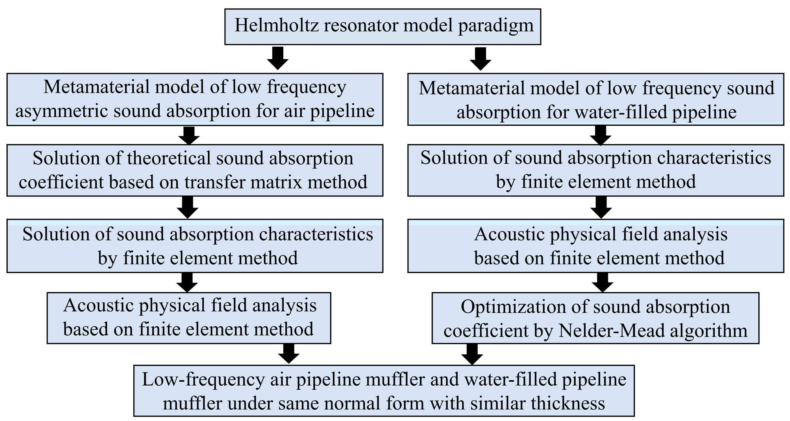
This section introduces the design paradigm of HR sound absorbers on the side branch of pipelines. Under this paradigm, we design low-frequency asymmetric absorption metamaterials for air pipelines and low-frequency and broadband composite absorbing metamaterial for water-filled pipelines. The flowchart of the methodology implemented is shown in Figure 1.
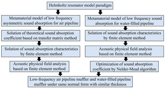
Figure 1.
Methodological flowchart of metamaterial for low-frequency asymmetric sound absorption of air pipeline and composite metamaterial for low-frequency sound absorption of water-filled pipeline based on Helmholtz basic paradigm.
First, we propose an asymmetric absorption metamaterial model for low-frequency sound elimination in air pipelines based on the Helmholtz cavity paradigm and provide theoretical solutions for the sound absorption coefficient and impedance. We then construct a model using the finite element method and provide analytical solutions for the sound absorption coefficient. Based on the theoretical solutions, we verify the validity of the finite element model. Continuing with the finite element method strategy, we solve the physical fields like pressure and velocity to study the low-frequency sound absorption mechanism. To match the structural impedance with water while maintaining a similar structure thickness, we introduce rubber materials based on the Helmholtz cavity paradigm and propose a composite metamaterial model for low-frequency sound absorption in water-filled pipelines. Using the finite element method, we calculate the sound absorption coefficients and physical field parameters of the materials, conduct studies on the absorption mechanism, and finally optimize the sound absorption coefficient using the Nelder–Mead optimization algorithm in COMSOL software.
2.1. Structure of the Low-Frequency Asymmetric Absorption Metamaterials for Air Pipeline
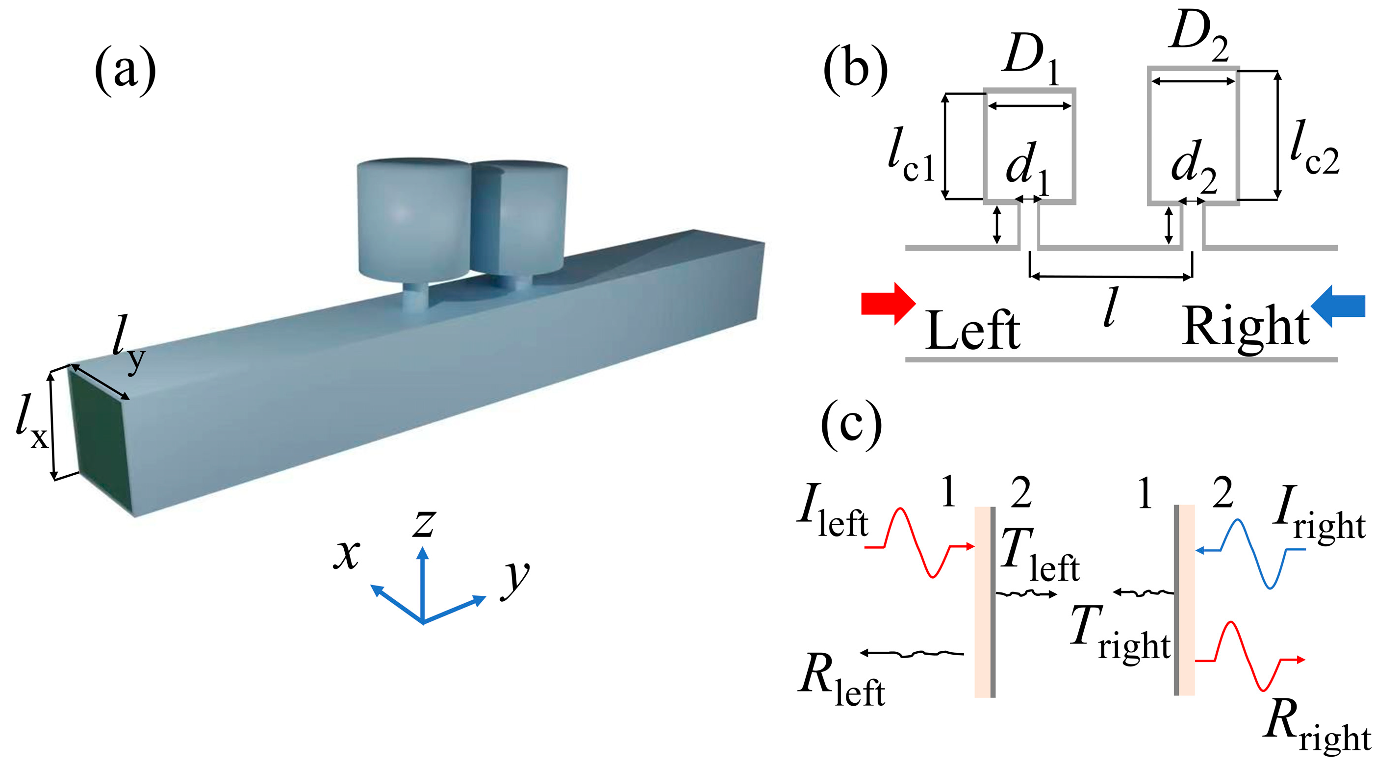
Figure 2a illustrates the schematic diagram of the suggested metamaterial designed for asymmetric absorption. The metamaterial is constructed from a rectangular pipe with attached HRs cascading in the z-direction. The pipe’s side lengths are established as lx = 50 mm and ly = 50 mm. Figure 2b depicts the cutaway perspective of the asymmetric absorbing metamaterial. In the schematic, ri and lni denote the radius and length of the ith HR neck, and i (=1, 2, 3, 4, 5, 6, 7, 8) signifies the HR count (as listed in Table 1). Di and lci refer to the diameter and depth of the ith HR cavity. l = 56 mm indicates distance between two successive HRs. Figure 2c illustrates the operating principle of an asymmetric sound-absorbing metamaterial. The metamaterial features two sides, designated as side 1 (left) and side 2 (right) for HR-1 and HR-2, respectively. When waves are incident from left to right, the metamaterial demonstrates efficient absorption of the wave energy. Conversely, when these sound waves traverse from the other side, the metamaterial turns highly scattering, leading to the reflection of most of the input sound waves.
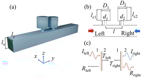
Figure 2.
(a) Schematic diagram of the asymmetric sound-absorbing metamaterials. (b) The cutaway view of the asymmetric sound-absorbing metamaterials along with geometric parameters. The thick red and blue arrows represent the directions of the incident sound. (c) Illustration of the asymmetric sound-absorbing metamaterial principle. I: incident; R: reflected; T: transmitted.

Table 1.
Geometrical dimensions of Helmholtz resonators.
All HRs in this paper are numbered, and the corresponding geometric parameters are listed in Table 1.
2.2. Theory of the Asymmetric Absorption Metamaterials
In the scope of this research, losses caused by viscosity and thermal effects can be represented by complex wave number and impedance as follows [41]:
where is a defined parameter and is cross-sectional area size (e = n for the neck and e = c is for the cavity). is the viscous boundary layer thickness, with being the viscosity of air. is the Prandtl number at atmospheric pressure with , (j is the imaginary unit), and is the heat capacity ratio of air. The impedance of HR can be articulated as follows [41]
where and represent the values of the length of the neck and the cavity. refers to the adjusted length calculated from the summation of two individual adjusted lengths . Here, and originate from the pressure radiations at the inconsistency transitioning from the neck area to the cavity portion of the HR and to the pipe, each individually [41]
where is the effective radius of the pipe, and is the area of the pipes.
The entire performance of the acoustical system can be characterized using the transfer matrix method. The comprehensive transfer matrix in Figure 2b is , where and are the representations of the transfer matrices for HR-i and the tube segment that exists between a pair of HRs [41]:
The transmittance and reflectance are obtained as
Subsequently, the absorption can be determined as follows: A = 1 − R − T.
When sound waves come in through the left port, the impedance at the neck of HR-1 () can be determined using the transfer impedance formula
When sound waves come in through the right port, the impedance at HR-2 neck is also calculated using the transfer impedance formula
2.3. Structure of the Low-Frequency Composite Absorption Metamaterials for Water-Filled Pipeline
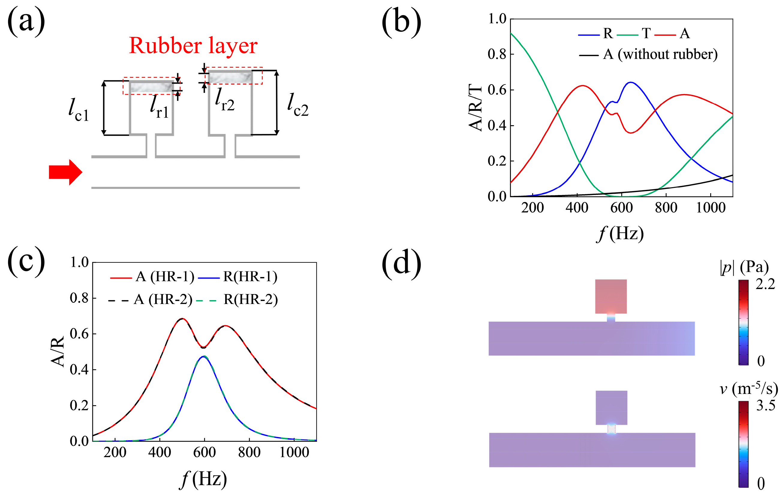
When dealing with sound absorption in water, there is a challenge with impedance mismatch between the incident sound and the HR pairs. Because of the huge modulus difference between water and air, the weak monopole resonance of chambers and low viscoelastic coefficients contribute to low energy dissipation efficiency. Both impedance matching and dissipation capacity indicate that directly applying sound-absorbing metamaterials designed for air pipelines to underwater environments is impractical. To overcome this issue, we introduce the viscoelastic rubber layer into the system to provide additional impedance. Figure 3 shows a cutaway view of the composite metamaterial formed by HRs with rubber coating. The rubber is bonded to the inner bottom surface of the cavity with the thickness of lr. The neck connects the sound field inside and outside of the cavity. Due to the abrupt change in cross-section, the cylinder of water and visco-thermal effects provide acoustic mass and acoustic resistance for HR. Additionally, the coated rubber layer and cavity contribute to the acoustic resistance and partial capacitance.
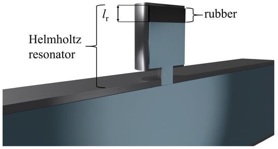
Figure 3.
Schematic diagram of the composite absorption metamaterials for water-filled pipelines.
2.4. Construction of Metamaterial Finite Element Model and Nelder–Mead Optimization Algorithm
All the finite element calculations in this paper are realized by the finite element simulation software COMSOL Multiphysics 6.1. Taking the asymmetric metamaterial for air pipeline sound absorption as an example, as shown in Figure 4a, the designed metamaterial is placed in the side branch of the waveguide, with the cavity connected to the waveguide through the neck. The dimensions of the waveguide are 1000 mm × 50 mm × 50 mm. Both the boundaries of the metamaterial and the waveguide are acoustic rigid. Considering the viscous friction effect and heat conduction effect of Helmholtz cavity, we use a thermal viscous acoustic module to introduce heat loss and viscous loss, and solve the momentum by Navier–Stokes equation, mass (continuity) equation, and energy conservation equation. In order to reduce the calculation complexity, we use the pressure acoustic module to calculate the pipeline area. To reduce computational complexity, we use the pressure acoustic module to calculate the sound field inside the pipeline. Two ports are set at both ends of the pipeline: one for setting the amplitude and phase of the incident sound pressure and the other for simulating the emission of sound waves. Two pipeline cross-sections are set at the incident and emission directions, with a distance of 68 mm between them. The sound absorption coefficient, reflection coefficient, and transmission coefficient are obtained by integrating the pressure at the cross-sections. Before the sound waves are generated, the initial sound pressure in the pressure acoustic region is set to 0 by adjusting the initial values under the pressure acoustic node. For the composite metamaterial applied to water-filled pipelines, the rubber section uses a linear elastic material from the solid mechanics module, with the same impedance damping factor added to the isotropic loss. The structural post-processing module is used to plot the sound pressure field, velocity field, energy dissipation density distribution, and displacement field of the rubber. The resonant sound absorption mechanism of the metamaterial structure is analyzed based on the distribution changes. By integrating the regional energy dissipation density, the distribution of energy dissipation in the structure after introducing the rubber is analyzed. As shown in Figure 4b, the simulation model is divided using a free tetrahedral mesh, ensuring that there are more than five mesh elements in the narrowest part of the structure.
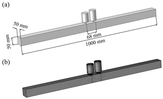
Figure 4.
The numerical simulation settings: (a) the finite element model; (b) finite element mesh generation.
The Nelder–Mead optimization algorithm used in this study is a gradient-free method. The specific optimization steps have been integrated into the COMSOL software as an optimization module. First, the optimization objective is set in the module according to the frequency to be optimized, with the target being the sound absorption coefficient variable in this study. Then, the optimization type is selected as ‘maximize the maximum target’, and the initial values of geometric variables, such as the neck length, neck radius, cavity depth, cavity radius, and rubber layer thickness, are set, along with the upper and lower bounds of the parameter optimization range. Finally, constraints are applied, such as the neck length not exceeding the cavity depth. After solving, the optimized sound absorption coefficient and corresponding geometric parameters can be obtained.
3. Results
This section mainly presents the sound absorption performance results of the two types of sound-absorbing metamaterials mentioned in the previous section, including the sound absorption coefficient, reflection coefficient, and transmission coefficient. The feasibility of the proposed model is determined through both analytical and numerical solutions. The mechanism of low-frequency sound absorption in pipelines is then revealed through the analysis of the physical field diagrams. Finally, the tunability of the sound absorption performance and broadband sound absorption capability are investigated.
3.1. Asymmetric Sound Absorption in Air Piplines
The graphs displayed in Figure 5a,b provide a representation of the absorption coefficient A (red lines), reflection coefficient R (blue lines), and transmission coefficient T (green lines) of the plane waves originating from the left and right ports. Both the theoretical (solid lines) and simulation (dashed lines) outcomes display satisfactory coherence. It is noteworthy that the transmittance values for waves originating from both directions are nearly identical. As a result, the different reflectance performance primarily contributes to the asymmetric absorptions. The reflectance of the system shows a significant dip at 403 Hz when the plane wave propagates from the left port to the right port. The theoretical maximum absorption is 90.5%, while the simulation result is 95.6% at 408 Hz. However, when the plane wave propagates from the right port to the left port, the majority of the acoustic energy is reverberated. In Figure 5b, the reflection coefficient increases to 76.9%, and the absorption coefficient diminishes to 18.8% in the theoretical calculation (16.9% absorptance at 408 Hz in the simulation) at 403 Hz. The asymmetric absorption performance is approached in a low-frequency bandwidth.
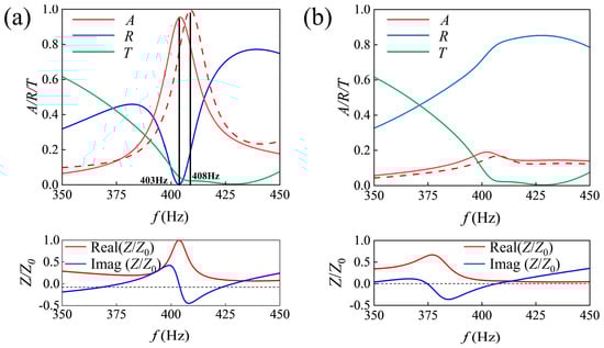
Figure 5.
(a) Reflection coefficient, transmission coefficient, absorption coefficient, and impedance of the asymmetric sound-absorbing metamaterial when waves incident from the left port. (b) The acoustic performance of the metamaterial when waves incident from the right port. The solid lines and dashed lines represent the theoretical and simulation outcomes. Real(Z/Z0) is the acoustic resistance, while Imag(Z/Z0) is acoustic reactance.
The mechanism of asymmetric absorption performance can be better understood by expounding it from the view of the equivalent boundary. At the resonance frequency of 403 Hz, HR-2 owns maximum reflection and minimum transmission and the reflection mode is inspired. The inspired resonator achieves a “soft” boundary on the cross-section of the pipeline. Consequently, the impedance at HR-2’s bottleneck approaches near-zero.
By adjusting the impedance of HR-1, the resistance becomes close to 1 and the reactance approaches 0, indicating that the impedance of HR-1 matches the impedance of air. The adjusted impedance of can be calculated by Formula (10) and is shown in the lower panel of Figure 5a. Under the condition of impedance matching, the absorption mode is excited by the incident wave from left port. However, when the plane waves enter via the right port, HR-2 maintains the “soft” boundary characteristic, meaning that the impedance of HR-2 () is almost zero. The impedance at the HR-2 neck can be calculated by Formula (11) and is shown in the lower panel of Figure 5b.
Under the mode coupling between Helmholtz resonators, the system has different impedance characteristics for waves that are incident from different ports, and then an asymmetric sound absorber is constructed. However, the mechanism of asymmetric sound absorption requires further study.
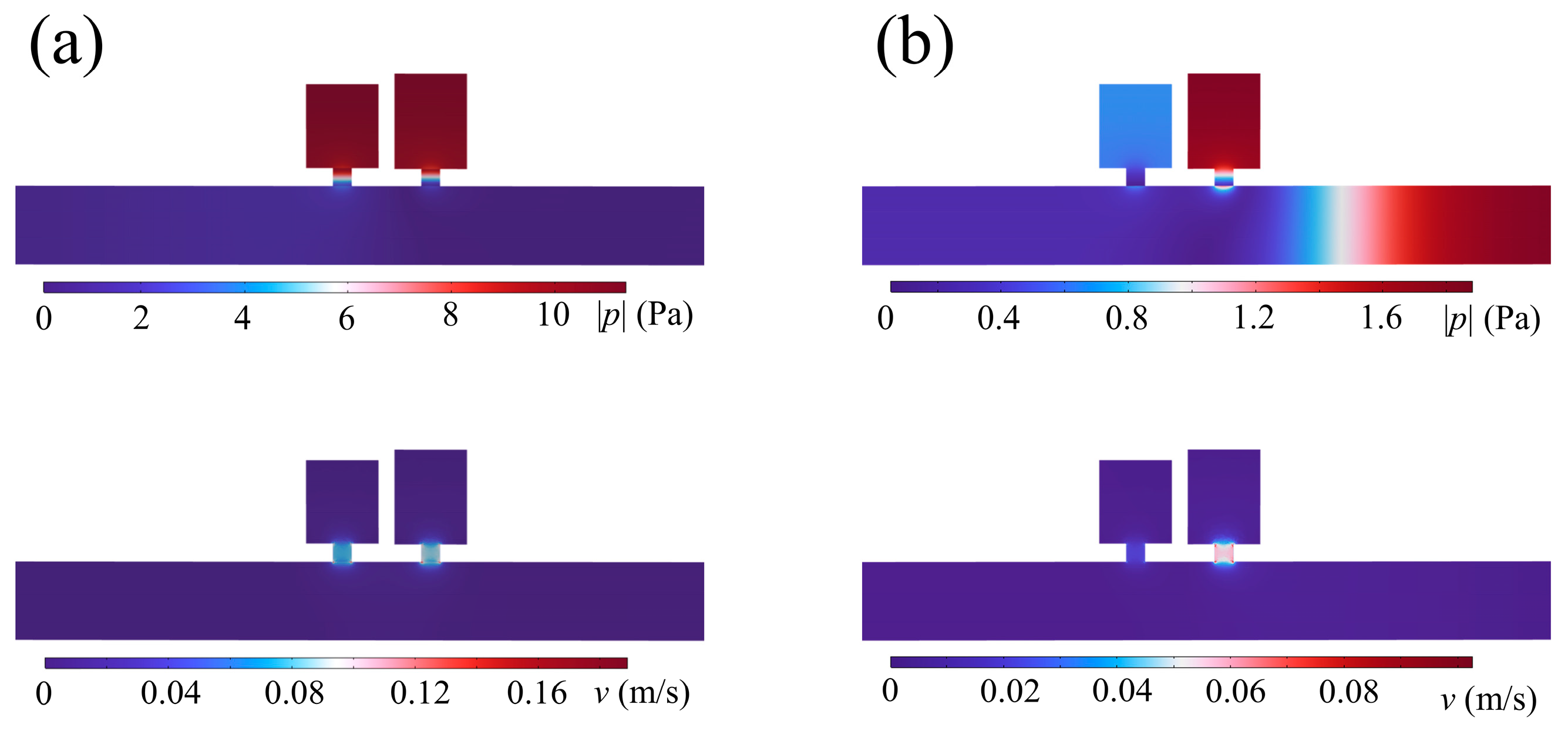
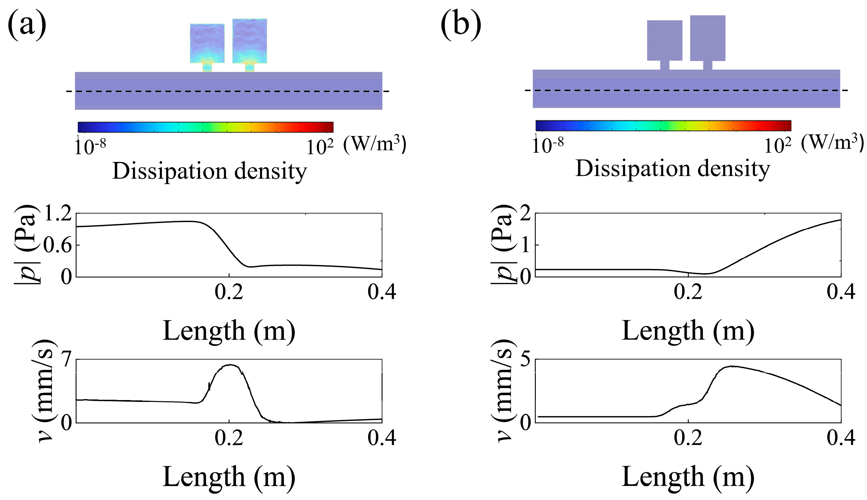
To better understand the mechanism of asymmetric absorption, we utilized the Acoustic–Thermoacoustic Interaction Frequency domain module in COMSOL to analyze the distributions of absolute sound pressure and particle velocity . When waves are emitted from the left port, both HRs are stimulated, resulting in a highly concentrated energy distribution, as shown in the upper panel of Figure 6a. In the lower panel of Figure 6a, a significant pressure reduction from inside to outside of the cavity due to resonance leads to a high concentration particle velocity distribution in the necks. This dissipation can be attributed to strong thermal viscosity under high acoustic velocity gradients. To quantify the energy dissipation intuitively, we measure the acoustic energy dissipation density, and the distribution map is displayed in the upper panel of Figure 7a. The acoustic energy is efficiently dissipated within the neck of the Helmholtz cavity, particularly in the thermal boundary layer and viscous boundary layer along the inner surface of the neck, where the dissipation density is several orders of magnitude higher than in the surrounding regions. Based on the simulation results of the absolute pressure and particle velocity v distributions, the mode coupling between the Helmholtz resonators (HRs) is further discussed. As shown in the lower panel of Figure 7a, and v distributions along the radial direction of the pipe centerline are plotted. The field profile of exhibits a node at HR-2, while the field profile of v shows an antinode, consistent with the behavior of acoustic waves radiating to a soft boundary. At this point, the interface of HR-2 perpendicular to the duct is considered to exhibit soft boundary characteristics, with HR-2 functioning in a reflection mode. In contrast, HR-1 operates in an absorption mode. The coupling of these two modes facilitates the efficient dissipation of the incident acoustic waves from the left side of the pipeline. In the upper panel of Figure 6b, when the plane waves are incident from the right port, the HRs are scarcely inspired, and only a small amount of sound energy is trapped within them. The distribution of the velocity field in the lower panel of Figure 6b is much weaker than in the case of left incidence, leading to minimal sound energy confinement. As shown in Figure 7b, when the wave is incident from the right port, the energy dissipation density is significantly lower compared to the incidence from the left port, indicating asymmetry in the absorption of incident acoustic energy. The pressure node of the field profile of and the antinode of the field profile of v further confirm the soft boundary effect of HR-2. The classical Helmholtz cavity offers multiple degrees of freedom in adjusting the center frequency, and the asymmetric sound-absorbing metamaterials based on mode coupling are supposed to possess similar characteristics.

Figure 6.
Absolute pressure and the respective particle velocities at 408 Hz when plane waves are incident from (a) left or (b) right port.
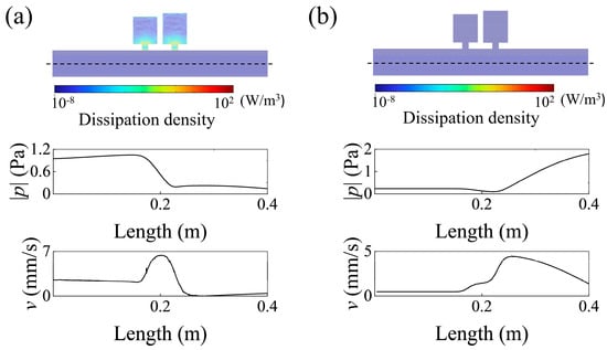
Figure 7.
(a) The upper panel shows the energy dissipation density distribution at 408 Hz, and the lower panels show the field profiles for absolute sound pressure and particle velocities along the black dashed cutline through the pipeline center when waves are incident from the left port. (b) The energy dissipation density distribution and the field profiles when waves are incident from the right port.
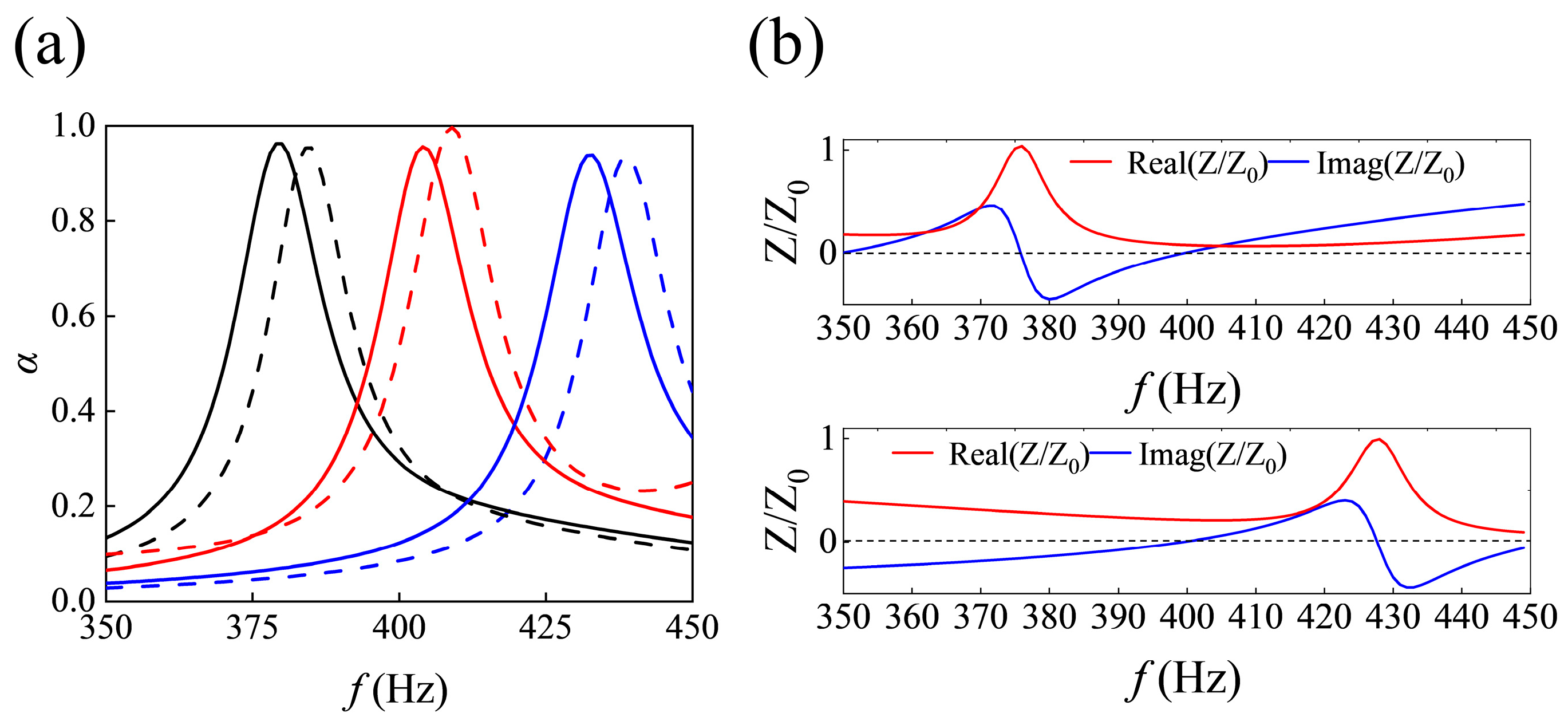
We discuss the absorption performance tenability based on parameter regulation. After designing the depth of the ith HR cavity lci and the length of the ith HR neck lni, metamaterials composed by coupling HR pairs of HR-3, HR-4, and HR-5, HR-6 achieve near-perfect absorption in the band from 379 Hz to 432 Hz. The relevant geometric parameters are listed in Table 1. As shown in Figure 8a, the absorption peaks (α > 0.9) are distributed at 376 Hz, 403 Hz, and 428 Hz (metamaterials are formed by HR-3 and HR-4; HR-1 and HR-2; and HR-5 and HR-6, respectively), while the simulation absorbing peaks are at 384 Hz, 408 Hz, and 439 Hz. The simulation results (represented by dashed lines) are in good agreement with the theoretical results. One reason for the frequency shift is that we simplified the acoustic pressure field in the cavity for the sake of calculation. The variation in geometric parameters is reflected in impedance modulation, which contributes to achieving tunable sound absorption. In fact, achieving ideal perfect absorption is challenging because reactance and resistance are not independent but are influenced by the same geometric parameters. Generally, quasi-perfect absorption is attained when reactance approaches 0 and resistance is close to 1. Figure 8b depicts the matched impedances of metamaterials formed by HR-3 and HR-4 and HR-5 and HR-6, respectively, revealing that the proposed metamaterial units have adaptable absorption band tunability at low frequencies.
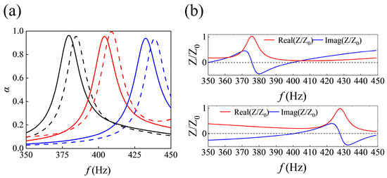
Figure 8.
(a) Absorptance of metamaterials constructed by HR-3 and HR-4 (black); HR-1 and HR-2 (red); HR-5 and HR-6 (blue) from left to right on frequency domain. Solid lines represent the theoretical calculation results, and dashed lines represent the numerical simulation results. (b) Impedances of metamaterials constructed by HR-3 and HR-4; HR-5 and HR-6.
3.2. Low-Frequency and Broadband Composite Absorbing Metamaterial in Water-Filled Piplines
We established a composite sound-absorbing metamaterial model composed of HR-1, HR-2, and rubber via COMSOL finite element software. Figure 9a shows a cutaway view of the composite metamaterial. The rubber thickness values are lr1 and lr2 for HR-1 and HR-2. Due to the abrupt change in the cross-section, the cylinder of water and visco-thermal effects provide acoustic mass and acoustic resistance for HR. Additionally, the coated rubber layer and cavity contribute to the acoustic resistance and partial capacitance. The simulations are conducted using the preset solid mechanics module of COMSOL to verify its performance. The density, Young’s modulus, Poisson’s ratio, and the loss factor of the viscoelastic rubber layer in this paper are selected as , , , and for calculation, and the thickness of the rubber layer inner cavities is . As shown in Figure 9b, the HR pairs, when combined with rubber layers, exhibit sound absorption coefficients of 0.6 at 500 Hz and 0.8 at 700 Hz. In contrast, when placed in a water-filled environment, the HR pairs without the rubber layer demonstrate near-zero sound absorption coefficients at low frequencies due to the lack of viscoelastic damping mechanisms. Introducing the rubber layer with viscoelastic losses makes it challenging for HR-2 to maintain resistance close to zero. As a result, HR-2 struggles to maintain the soft boundary characteristics and instead behaves as a low-frequency sound absorber. As shown in Figure 9c, we calculated the sound absorption and reflection coefficients of HR-1 and HR-2, respectively. The results show that both resonant frequencies of the cavities are 600 Hz. However, due to incomplete impedance matching, partially incident acoustic energy is reflected. Because the geometric parameters of HR-1 and HR-2 are very similar, and after regulating the impedance by introducing rubber layers, both cavities exhibit nearly identical sound absorption coefficient curves. So, only the sound absorption performance of HR-1 has been researched. We plotted the absolute pressure and particle velocity distributions of HR-1 at 600 Hz in Figure 9d. Under the excitation of the incident sound wave, sound pressure accumulates within the HR-1 cavity at 600 Hz, and a high vibration velocity distribution is generated at the neck due to the pressure difference between the interior and exterior of the cavity. The results suggest that the absorption characteristics are caused by quasi-Helmholtz resonance caused by the Helmholtz cavity with the inside rubber layer. However, the precise mechanisms underlying sound energy dissipation in these structures require further investigation to fully understand the role of the rubber layer and its interaction with sound waves.
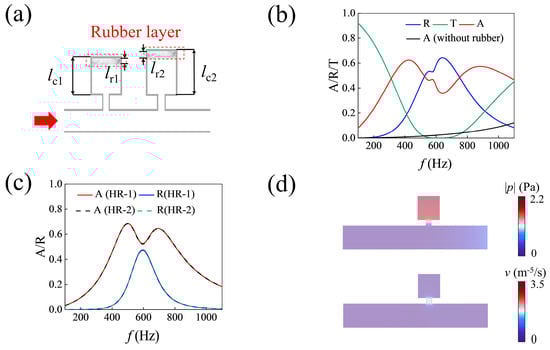
Figure 9.
(a) The cutaway view of the HR pairs with rubber layer (gray rectangular area in the red dashed box). (b) Absorptance, reflectance, and transmittance curves of the composite metamaterial formed by HR-1 and HR-2 pairs for water-filled pipeline with (red, blue, and green lines) and without (black line) rubber layer. (c) Absorptance and reflectance curves of HR-1 (red and blue lines) and HR-2 (black and green dashed lines). Both HRs are bonded with rubber layers. (d) The distributions of absolute sound pressure |P| and particle velocity v of HR-1 with the rubber layer.
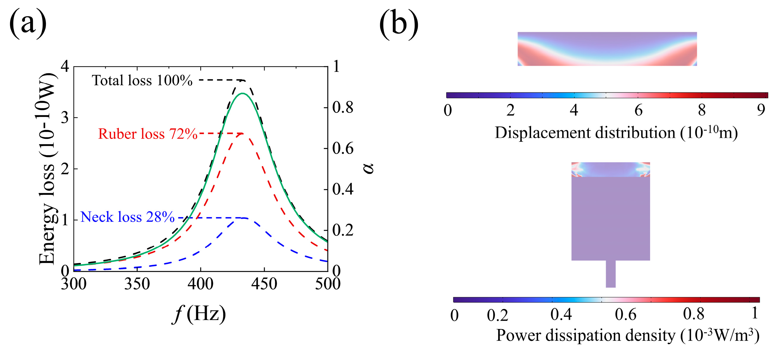
We use the Nelder–Mead algorithm to optimize the absorption coefficient of Helmholtz resonance (HR) cavities with a rubber layer. The optimization considers neck length, diameter, cavity depth, and rubber layer thickness as variables to maximize the absorption coefficient over a constrained frequency bandwidth. Figure 10a illustrates that the optimized HR-7 achieved an absorption coefficient of 0.85 at 446 Hz, with the rubber layer thickness set to 3 mm. The relevant geometric parameters of HR-7 are listed in Table 1. Detailed geometric parameters are listed in Table 1. Furthermore, to analyze the sound absorption mechanism of the Helmholtz resonator with the rubber layer in water-filled pipelines, we plotted the energy dissipation density distribution and displacement distribution diagrams for HR-7. The upper panel of Figure 10b presents the energy dissipation density profile of HR-7. The profile illustrates that, unlike traditional Helmholtz resonance in air, the region of higher energy density is concentrated in the rubber layer rather than the neck. This shift indicates that introducing the rubber layer not only modifies the impedance but also enhances the energy dissipation for incoming sound waves. In Figure 10a, we also plotted the percentage of energy loss occurring in the rubber layer and the neck. It is noted that viscous heat loss at the neck accounts for 28% of the total energy loss, with the majority of the energy being dissipated in the rubber layer. The lower half of Figure 10b depicts the displacement distribution of the rubber layer. During quasi-Helmholtz resonance, the larger displacements observed in the rubber layer suggest that strong sound–structure coupling occurs at the boundary between the water and the rubber layer. Because of the sound–structure coupling, the incoming longitudinal waves are predominantly converted into shear waves. These shear waves are more easily dissipated within the viscoelastic material due to internal friction and elastic relaxation processes. As a result, the composite metamaterial unit, composed of the HR cavity and the rubber layer, demonstrates exceptional low-frequency sound absorption capabilities for water-filled pipelines.
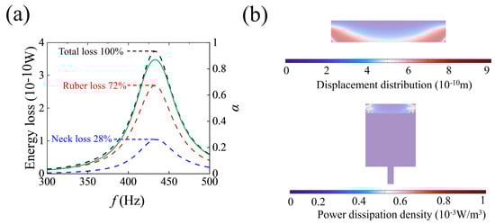
Figure 10.
(a) The absorption spectrum of HR-7 with rubber layer (green line) and the energy loss in rubber layer (red dashed line) and neck (blue dashed line) of HR-7 with rubber layer. (b) The upper panel shows the displacement distribution of the rubber layer of HR-7 at 446 Hz. The lower panel shows the power dissipation density distribution of HR-7.
Broadband low-frequency absorption capability is significant in noise reduction for pipeline systems because the noise in the industrial pipeline system usually manifests as a line spectrum in broadband. We construct a composite metamaterial by parallel combination of four basic composite metamaterial units to achieve broadband acoustic absorption in water-filled pipelines. A 3 mm rubber layer is attached to the bottom of each basic unit, with the corresponding geometric parameters of HR-8, HR-9, HR-10, and HR-11 listed in Table 1. Figure 11a–d illustrate that the four basic units demonstrate quasi-Helmholtz resonance under incident wave excitation at 388 Hz, 425 Hz, 456 Hz, and 496 Hz, respectively. The absorption spectra of the individual units are depicted in Figure 11e. Despite the relatively low peak values of the analytical absorption coefficients of the basic units, the composite metamaterial unit exhibits a markedly enhanced overall absorption profile. The disparity in the absorption characteristics between the basic and composite units indicates that coherent coupling among the basic units results in extended bandwidth. The coupled composite metamaterial demonstrates an absorption coefficient exceeding 0.8 across the broadband frequency range of 380–508 Hz.
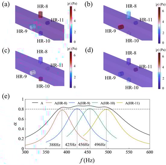
Figure 11.
(a–d) The composite metamaterial is formed by HR-8, HR-9, HR-10, and HR-11, with rubber layers attached to the bottom of each cavity. The distributions of absolute sound pressure |P| of composite metamaterial at 388 Hz, 425 Hz, 456 Hz, and 496 Hz. (e) The absorption spectra of four basic units and the composite metamaterial unit.
3.3. Final Closure of the Results
We designed metamaterials based on the HR paradigm, which are applied to low-frequency sound absorption in air pipelines and water-filled pipelines. The asymmetric absorption metamaterial for air pipelines has a maximum thickness of 71 mm, which is smaller than the resonance-labyrinthine silencing structure of 125 mm proposed by Qi et al. [39]. The composite metamaterial designed for water-filled pipelines has a maximum thickness of 31.5 mm, much smaller than the simple HR structure proposed by Liu et al. [40]. More importantly, when the HR configurations for low-frequency sound absorption, as proposed by Liu et al. [40] and Long et al. [41], are used for sound absorption in water-filled and air pipelines, the structural thicknesses are 300 mm and 71 mm, respectively, differing by 229 mm. In contrast, under the HR paradigm we proposed, the thicknesses are 31.5 mm and 71 mm, differing by only 39.5 mm. Based on our design paradigm, the silencers for different media pipelines have similar thickness, which reduces the complexity of designing silencers for complex pipeline systems in confined spaces. However, compared to the noise frequency band of 315–500 Hz for water-filled pipelines mentioned in Ref. [3], the composite metamaterial we have constructed for sound absorption in water pipelines has a narrower absorption band, ranging from 380 to 508 Hz. In the future, the arrangement of composite units along the axial direction of the pipeline will be considered to further broaden the sound absorption bandwidth.
4. Conclusions
In conclusion, we proposed a Helmholtz resonator (HR) design paradigm for low-frequency sound absorption in pipelines with different media. Based on this design paradigm, asymmetric absorption metamaterials for low-frequency air pipelines and composite metamaterials for low-frequency sound absorption in water-filled pipelines were designed. For the asymmetric absorption metamaterials, the sound absorption performance was analyzed using both theoretical and numerical methods. At 403 Hz, when the plane wave is emitted from one side of the waveguide, almost all the sound energy is absorbed, with the sound absorption coefficient reaching 0.905, while most of the sound energy is reflected from the opposite side. The sound pressure and velocity distribution maps calculated by the finite element method show that the asymmetry in absorption is attributed to the coupling between the absorption and reflection acoustic modes of the HRs. Furthermore, we demonstrated that an efficient absorption peak can be modulated within the 376 Hz to 428 Hz frequency range. For sound absorption in water-filled pipelines, we introduced rubber materials into the HR design paradigm and designed composite sound absorption metamaterials. The rubber layer provides additional acoustic resistance for matching the structure with water because the modulus of water is far larger than air. Simultaneously, under quasi-Helmholtz resonance, incident longitudinal waves are converted to transverse waves within the viscoelastic rubber layer and greatly dissipated. Notably, due to the additional acoustic resistance provided by the viscoelastic rubber, the HR, which typically exhibits soft boundary characteristics in air pipelines, struggles to maintain near-zero impedance. Under resonance conditions, the HR no longer exhibits a reflection mode but functions as a low-frequency sound absorber. We optimized the composite metamaterial unit by using the Nelder–Mead optimization algorithm, achieving an absorption coefficient of 0.85 at 446 Hz for the optimized unit. Finally, by constructing a coupled composite metamaterial with four parallel basic composite metamaterial units in the same pipeline section, we achieved broadband sound absorption from 380 Hz to 508 Hz, with the absorption coefficients exceeding 0.8. Under the HR design paradigm, the thicknesses of the asymmetric absorption metamaterial and the composite absorption metamaterial are 71 mm and 31.5 mm, respectively, both being similar and extremely thin. The two types of metamaterials designed based on the proposed Helmholtz cavity basic paradigm can be applied to low-frequency sound absorption in both air pipelines and water-filled pipelines. When applied to systems composed of pipelines that transport both air and liquids, there is no need to design different configurations of silencers for pipelines with different media. This reduces the complexity of designing silencers for the system and, due to the use of a single paradigm, improves reliability. By addressing the issue of excessive thickness differences in silencers caused by the large impedance mismatch between air and water, the low-frequency silencers we propose, due to their relatively thin thickness, can still be applied in pipeline systems located in narrow spaces where sound absorption design is required. The sound absorption bandwidth of the designed metamaterials is still not wide enough. In the future, the sound absorption bandwidth will be further broadened by arranging metamaterial units along the axial direction of the pipeline.
Author Contributions
Conceptualization, B.L. and Z.L.; methodology, B.L. and S.L.; software, B.Z.; validation, B.L. and A.L.; formal analysis, Z.L.; investigation, S.L.; resources, B.L.; data curation, B.L.; writing—original draft, B.L. and S.L.; writing—review and editing, B.L. and Z.L.; visualization, S.L.; supervision, A.L.; project administration, S.L.; funding acquisition, S.L. All authors have read and agreed to the published version of the manuscript.
Funding
This work was supported by the National Natural Science Foundation of China under Grant 12104114 and Grant 12404541 and the National Key Research and Development Program under Grant 2022YFC2803704.
Institutional Review Board Statement
Not applicable.
Informed Consent Statement
Not applicable.
Data Availability Statement
The original contributions presented in the study are included in the article; further inquiries can be directed to the corresponding author.
Acknowledgments
We extend our sincere gratitude to all the authors for their invaluable contributions and dedicated efforts, which have been instrumental in the successful completion of this work.
Conflicts of Interest
The authors declare no conflicts of interest.
References
- Yu, D.L.; Du, C.Y.; Shen, H.J.; Liu, J.W.; Wen, J.H. An analysis of structural-acoustic coupling band gaps in a fluid-filled periodic pipe. Chin. Phys. Lett. 2017, 34, 076202. [Google Scholar] [CrossRef]
- Catron, F.; Fagerlund, A. Noise generation and propagation effects on piping system components. Noise Control Eng. J. 2009, 57, 570–577. [Google Scholar] [CrossRef]
- Celik, S.; Nsofor, E.C. Studies on the flow-induced noise at the evaporator of a refrigerating system. Appl. Therm. Eng. 2011, 31, 2485–2493. [Google Scholar]
- Ye, L.; Wang, X.; Wu, W.; Ma, H.; Li, N. Study on acoustic characteristics of air pipeline with guide vane and bionic guide vane. Ocean Eng. 2023, 284, 115197. [Google Scholar]
- Gong, F.L.; Li, Q.; Sun, X.M.; Kong, Y.; Liu, S. Theoretical and experimental study of a two-dimensional circular stealth acoustic lens. Phys. Scr. 2024, 99, 115945. [Google Scholar]
- Zheng, B.; Liu, Z.; Liu, B.; Chen, X.; An, D.; Cao, G.; Liu, S. High-Throughput Superresolved Focal Imaging Based on a Phase-Modulated Acoustic Superoscillatory Lens. Phys. Rev. Appl. 2022, 18, 014048. [Google Scholar] [CrossRef]
- Kim, J.W.; Hwang, G.; Lee, S.J.; Kim, S.H.; Wang, S. Three-dimensional acoustic metamaterial Luneburg lenses for broadband and wide-angle underwater ultrasound imaging. Mech. Syst. Signal Process 2022, 179, 109374. [Google Scholar]
- Zaremanesh, M.; Bahrami, A. Two-dimensional honeycomb lattice structure for underwater acoustic cloaking using pentamode materials. Phys. Scr. 2023, 99, 015946. [Google Scholar] [CrossRef]
- Raza, M.; Ahsan, M.; Alonazi, W.B.; Naqvi, S.A.; Braaten, B. Design and analysis of arbitrary shaped bifunctional cloaks for multifunctional material composites. Phys. Scr. 2023, 98, 115020. [Google Scholar]
- Wang, Y.; Ge, Y.; Zhou, Z.; Chen, Z.D. Transmissive invisibility cloak using phase gradient metasurfaces. Phys. Scr. 2024, 99, 085527. [Google Scholar]
- Yang, R.; Zhang, X.; Wang, G. A hybrid acoustic cloaking based on binary splitting metasurfaces and near-zero-index metamaterials. Appl. Phys. Lett. 2022, 120, 021603. [Google Scholar]
- Xue, Y.; Zhao, J.; Zhang, X.; Sessler, G.M.; Kupnik, M. Acoustic energy harvesting with irradiated cross-linked polypropylene piezoelectret films. Phys. Scr. 2019, 94, 095002. [Google Scholar]
- Ma, K.J.; Tan, T.; Liu, F.R.; Zhao, L.C.; Liao, W.H.; Zhang, W.M. Acoustic energy harvesting enhanced by locally resonant metamaterials. Smart Mater. Struct. 2020, 29, 075025. [Google Scholar]
- Ma, K.; Tan, T.; Yan, Z.; Liu, F.; Liao, W.H.; Zhang, W. Metamaterial and Helmholtz coupled resonator for high-density acoustic energy harvesting. Nano Energy 2021, 82, 105693. [Google Scholar]
- Bok, E.; Park, J.J.; Choi, H.; Han, C.K.; Wright, O.B.; Lee, S.H. Metasurface for water-to-air sound transmission. Phys. Rev. Lett. 2018, 120, 044302. [Google Scholar]
- Huang, Z.; Zhao, Z.; Zhao, S.; Cai, X.; Zhang, Y.; Cai, Z.; Yang, J. Lotus metasurface for wide-angle intermediate-frequency water–air acoustic transmission. ACS Appl. Mater. Interfaces 2021, 13, 53242–53251. [Google Scholar] [CrossRef] [PubMed]
- Zhou, H.T.; Zhang, S.C.; Zhu, T.; Tian, Y.Z.; Wang, Y.F.; Wang, Y.S. Hybrid metasurfaces for perfect transmission and customized manipulation of sound across water–air interface. Adv. Sci. 2023, 10, 2207181. [Google Scholar]
- Liu, J.; Li, Z.; Liang, B.; Cheng, J.C.; Alù, A. Remote Water-to-Air Eavesdropping with a Phase-Engineered Impedance Matching Metasurface. Adv. Mater. 2023, 35, 2301799. [Google Scholar]
- Zhou, P.; Jia, H.; Bi, Y.; Yang, Y.; Yang, Y.; Zhang, P.; Yang, J. Water–air acoustic communication based on broadband impedance matching. Appl. Phys. Lett. 2023, 123, 191701. [Google Scholar]
- Ma, G.; Yang, M.; Xiao, S.; Yang, Z.; Sheng, P. Acoustic metasurface with hybrid resonances. Nat. Mater. 2014, 13, 873–878. [Google Scholar]
- Duan, M.; Yu, C.; Xu, Z.; Xin, F.; Lu, T. Acoustic impedance regulation of Helmholtz resonators for perfect sound absorption via roughened embedded necks. Appl. Phys. Lett. 2020, 117, 151904. [Google Scholar] [CrossRef]
- Dannemann, M.; Kucher, M.; Kunze, E.; Modler, N.; Knobloch, K.; Enghardt, L.; Sarradj, E.; Höschler, K. Experimental Study of Advanced Helmholtz Resonator Liners with Increased Acoustic Performance by Utilising Material Damping Effects. Appl. Sci. 2018, 8, 1923. [Google Scholar] [CrossRef]
- Huang, S.; Fang, X.; Wang, X.; Assouar, B.; Cheng, Q.; Li, Y. Acoustic perfect absorbers via Helmholtz resonators with embedded apertures. J. Acoust. Soc. Am. 2019, 145, 254–262. [Google Scholar] [CrossRef] [PubMed]
- Papadakis, N.M.; Stavroulakis, G.E. FEM Investigation of a Multi-Neck Helmholtz Resonator. Appl. Sci. 2023, 13, 10610. [Google Scholar] [CrossRef]
- Qu, S.; Gao, N.; Tinel, A.; Morvan, B.; Romero-García, V.; Groby, J.P.; Sheng, P. Underwater metamaterial absorber with impedance-matched composite. Sci. Adv. 2022, 8, eabm4206. [Google Scholar] [CrossRef]
- Li, Z.; Yang, D.Q.; Liu, S.L.; Yu, S.Y.; Lu, M.H.; Zhu, J.; Chen, Y.F. Broadband gradient impedance matching using an acoustic metamaterial for ultrasonic transducers. Sci. Rep. 2017, 7, 42863. [Google Scholar] [CrossRef]
- Gan, Z.; Mo, Y.; Fan, H.; Zhu, Y.; Zhang, H. Ultra-broadband underwater meta-absorber with gradient impedance-matched composite material. Smart. Mater. Struct. 2024, 33, 115018. [Google Scholar] [CrossRef]
- Wu, B.; Chen, B.; Ma, S.; Zhang, D.; Zu, H.R. An Ultra-Broadband and Highly-Efficient Metamaterial Absorber with Stand-Up Gradient Impedance Graphene Films. Materials 2023, 16, 1617. [Google Scholar] [CrossRef]
- Mo, J.; Peng, Z.; Wang, X. Achieving Enhanced Sound Insulation through Micromembranes-Type Acoustic Metamaterials. Appl. Sci. 2022, 12, 1950. [Google Scholar] [CrossRef]
- Pan, L.; Martellotta, F. A Parametric Study of the Acoustic Performance of Resonant Absorbers Made of Micro-perforated Membranes and Perforated Panels. Appl. Sci. 2020, 10, 1581. [Google Scholar] [CrossRef]
- Zhao, J.; Li, X.; Wang, Y.; Wang, W.; Zhang, B.; Gai, X. Membrane acoustic metamaterial absorbers with magnetic negative stiffness. J. Acoust. Soc. Am. 2017, 141, 840–846. [Google Scholar] [CrossRef] [PubMed]
- Guo, J.; Zhang, X.; Fang, Y.; Jiang, Z. A compact low-frequency sound-absorbing metasurface constructed by resonator with embedded spiral neck. Appl. Sci. 2020, 117, 221902. [Google Scholar] [CrossRef]
- Kong, D.Q.; Huang, S.B.; Li, D.; Cai, C.; Zhou, Z.; Liu, B.T.; Cao, G.X.; Chen, X.F.; Li, Y.; Liu, S.C. Low-frequency multi-order acoustic absorber based on spiral metasurface. J. Acoust. Soc. Am. 2021, 151, 12–18. [Google Scholar] [CrossRef]
- Almeida, G.D.N.; Vergara, E.F.; Barbosa, L.R.; Brum, R. Low-frequency sound absorption of a metamaterial with symmetrical-coiled-up spaces. Appl. Acoust. 2021, 172, 107593. [Google Scholar] [CrossRef]
- Hong, Z.; Wu, F.; Bai, C.; An, K.; Wang, J.; Yang, B. Two-port network spiral type asymmetric absorption system. Appl. Acoust. 2022, 192, 108730. [Google Scholar] [CrossRef]
- Ma, P.S.; Kim, H.S.; Lee, S.H.; Seo, Y.H. Quasi-perfect absorption of broadband low-frequency sound in a two-port system based on a micro-perforated panel resonator. Appl. Acoust. 2022, 186, 108449. [Google Scholar] [CrossRef]
- Meng, D.; Li, L.; Wu, Z. Helmholtz resonator-based acoustic metamaterials enabling broadband asymmetric sound absorption and ventilation. J. Low Freq. Noise Vib. Act. Control 2023, 42, 1242–1250. [Google Scholar] [CrossRef]
- Fu, C.; Zhang, X.; Yang, M.; Xiao, S.; Yang, Z. Hybrid membrane resonators for multiple frequency asymmetric absorption and reflection in large waveguide. Appl. Phys. Lett. 2017, 110, 021901. [Google Scholar] [CrossRef]
- Qi, H.B.; Fan, S.W.; Jiang, M.; Tang, X.L.; Wang, Y.S. Low-frequency ultra-broadband ventilated muffler based on a resonance-labyrinthine metamaterial. Extrem. Mech. Lett. 2024, 67, 102120. [Google Scholar] [CrossRef]
- Liu, B.; Yang, L. Transmission of low-frequency acoustic waves in seawater piping systems with periodical and adjustable helmholtz resonator. J. Mar. Sci. Eng. 2017, 5, 56. [Google Scholar] [CrossRef]
- Long, H.; Cheng, Y.; Liu, X. Asymmetric absorber with multiband and broadband for low-frequency sound. Appl. Phys. Lett. 2017, 111, 143502. [Google Scholar]


Disclaimer/Publisher’s Note: The statements, opinions and data contained in all publications are solely those of the individual author(s) and contributor(s) and not of MDPI and/or the editor(s). MDPI and/or the editor(s) disclaim responsibility for any injury to people or property resulting from any ideas, methods, instructions or products referred to in the content. |
© 2025 by the authors. Licensee MDPI, Basel, Switzerland. This article is an open access article distributed under the terms and conditions of the Creative Commons Attribution (CC BY) license (https://creativecommons.org/licenses/by/4.0/).