
A Process Decision-Making Method for Planar Machining of Box-Type Components

Abstract
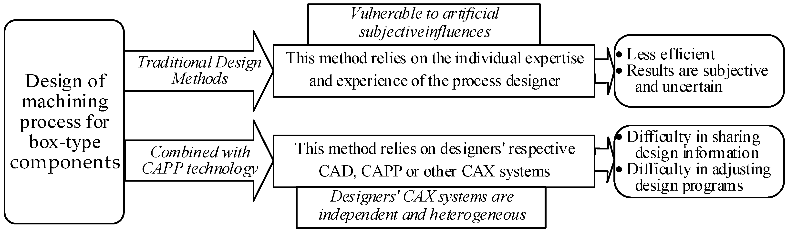
:1. Introduction
2. Related Work
- (1)
- Ontology Representation
- (2)
- Ontology Construction
- (3)
- Ontology Development
- (4)
- Ontology Reasoning
3. Constructing a Hierarchical Information Model for Process Decision-Making
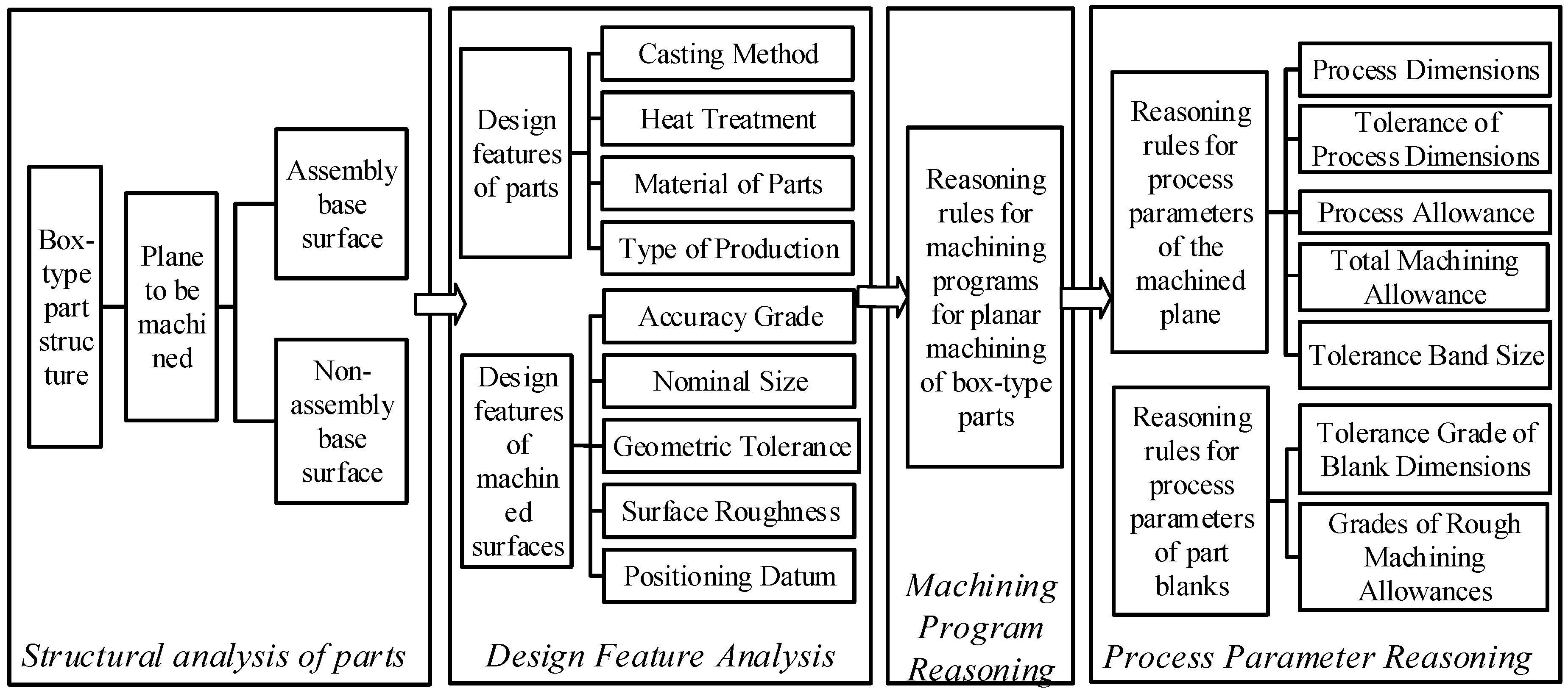
3.1. Planar Machining Process Decision-Making
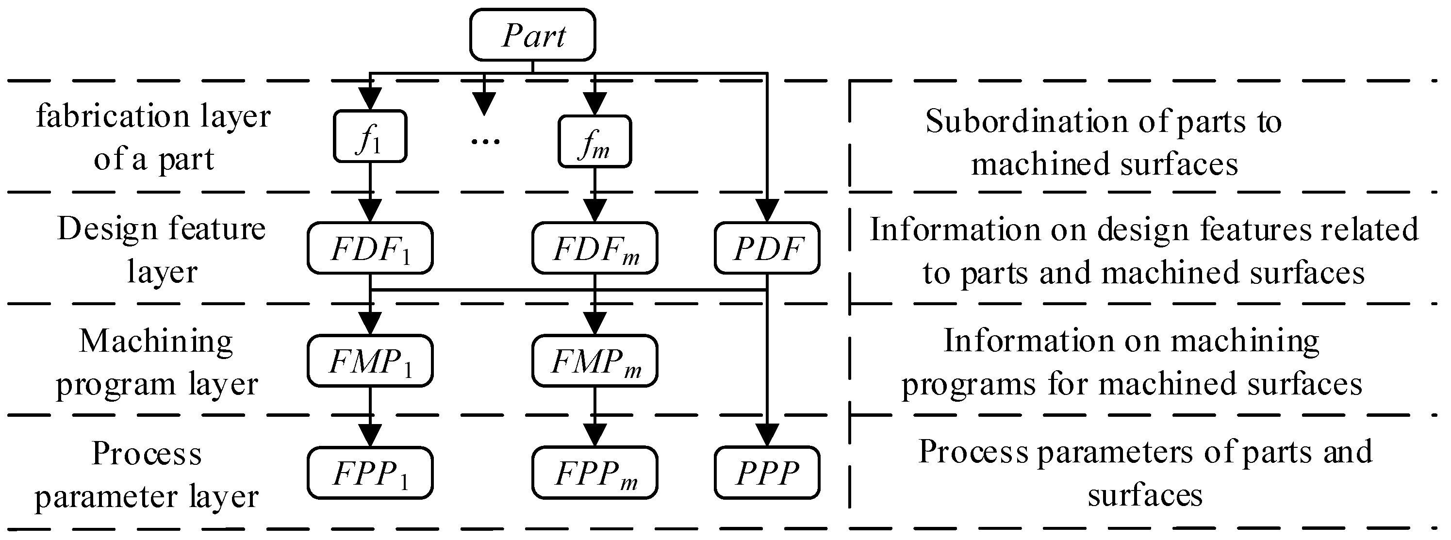
3.2. Hierarchical Information Representation Model for Machining Process Decision-Making
3.2.1. Part Structure Layer
3.2.2. Design Features Layer
- Production types (PT) can be classified into small-batch production, medium-batch production, and large-batch production.
- Common materials (PM) for box-type parts include cast steel, gray cast iron, and ductile iron.
- Casting methods (CM) typically used for box-type parts involve sand casting (manual molding and machine molding), shell molding, metal mold casting, and investment casting.
- Heat treatment methods (HT) commonly applied to box-type parts include annealing, normalizing, aging treatment, and quenching.
3.2.3. Processing Program Layer
3.2.4. Process Parameter Layer
4. Ontology Modeling for Process Decision-Making
4.1. Acquiring Domain Knowledge for Process Decision-Making
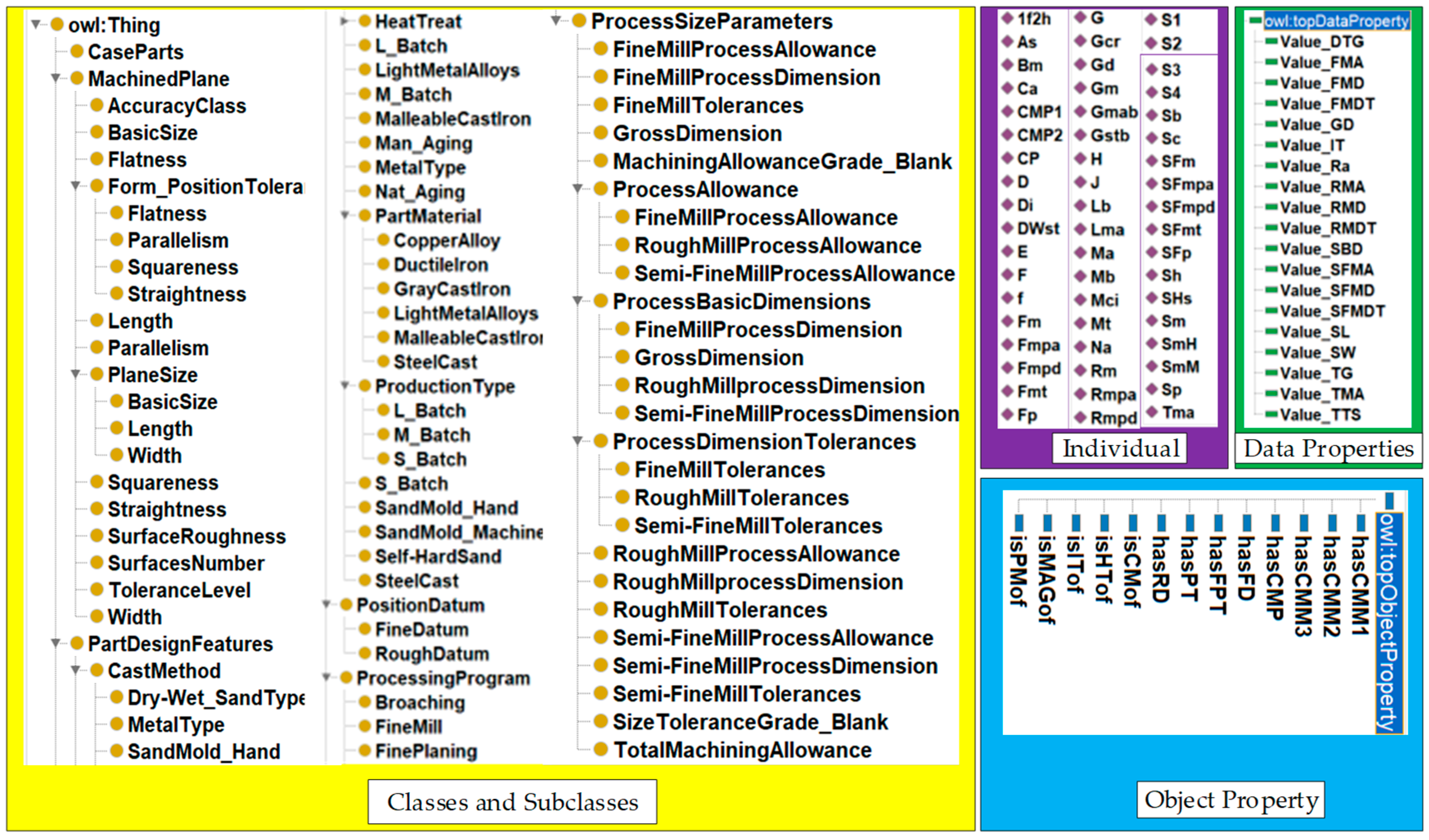
4.2. Defining Classes and Their Hierarchical Relationships
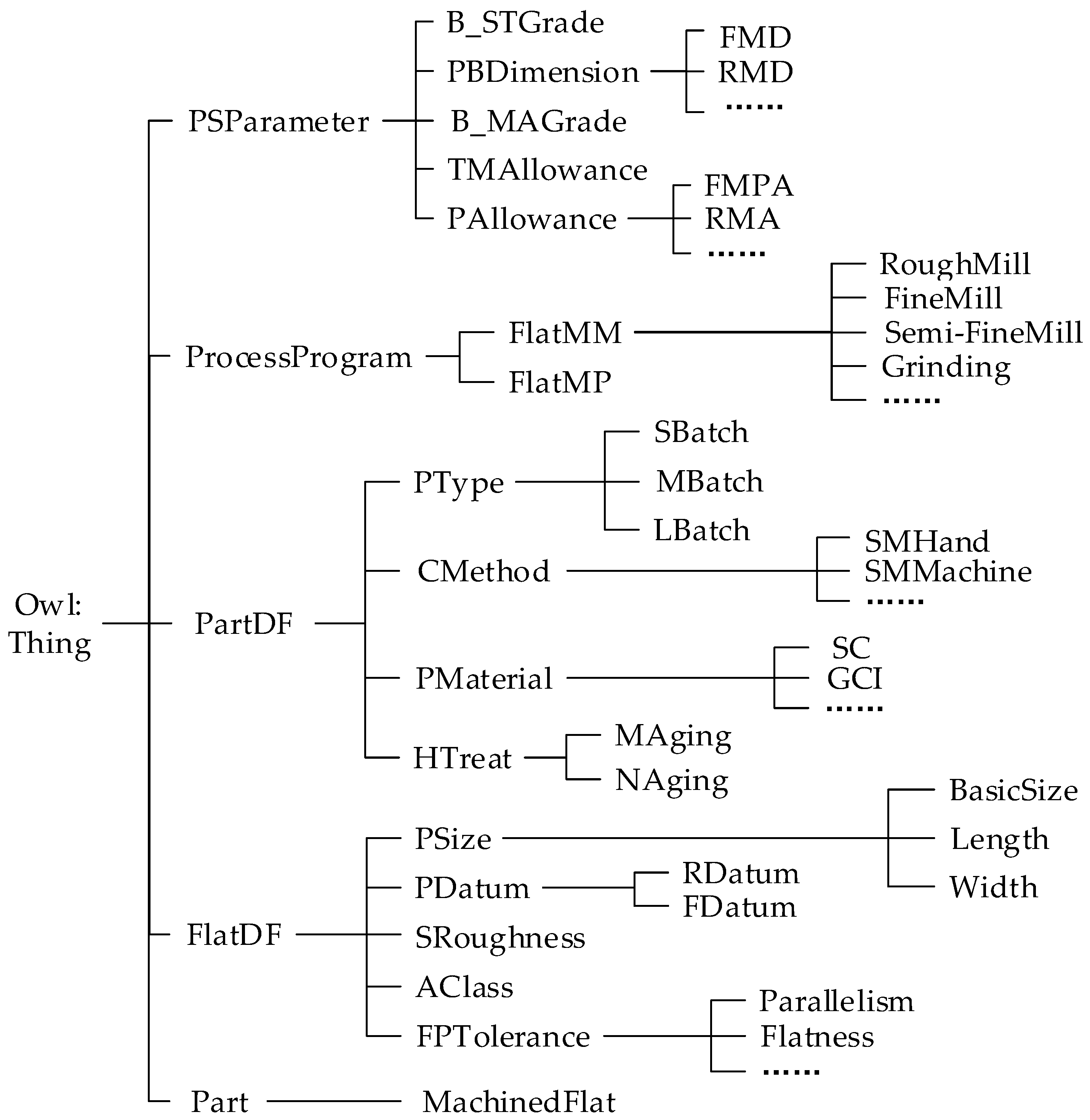
- In the ontology editing tool Protégé, “owl:Thing“ serves as an abstract class and the parent class of all entities. Its subclasses—”Part”, “FlatDF”, “PartDF”, “ProcessProgram” and “PSParameter”—respectively represent box-type parts, design features of the machined surface, design features of the part, machining schemes, and process dimension parameters.
- The subclass “MachineFlat” under “Part” represents the machined surface.
- The subclass “FlatDF” includes “PSize”, “PDatum”, “SRoughness”, “AClass”, and “FPTolerance”, which, respectively, denote nominal dimensions, positioning reference, surface roughness, accuracy class, and geometrical tolerance constraints. The subclass “PSize” further includes “BasicSize”, “Length”, and “Width”, which define the basic size, length, and width of the machined surface. The subclass “PDatum” consists of “FDatum” and “RDatum”, representing finishing datum and rough machining datum, respectively. The subclass “FPTolerance” represents various geometrical tolerances.
- The subclass “PartDF” includes “HTreat”, “PMaterial”, “CMethod”, and “PType”, which correspond to the heat treatment method, part material, casting method, and production type, respectively. These subclasses align with the design features of the part described in Section 3.2.2.
- The subclass “ProcessProgram” contains “FlatMP” and “FlatMM”, which denote machining schemes and machining methods for planar surfaces. The subclass “FlatMM” further categorizes various machining methods, such as rough milling, finish milling, and grinding.
- The subclass “PSParameter” consists of “PAllowance”, “PBDimension”, “TMAllowance”, “B_MAGrade”, and “B_STGrade”, representing machining allowance, process dimensions, total machining allowance, blank machining allowance grade, and blank size tolerance grade, respectively. Additionally, the subclasses “PAllowance” and “PBDimension” specify the allowance and dimensions for each machining operation.
4.3. Definition and Constraint of Attributes
5. Planar Machining Process Decision for Box-Type Components
- Rule1-1: Part(?x) ∧ ProductionType(?y) ∧ hasPT(?x,Lb) -> isCMof(?x, SmM)
- Rule1-2: Parts(?x) ∧ isPMof(?x,Gcr) ∧ isCMof(?x,SmM) -> Value_DTG(?x,10) ∧ isMAGof(?x,G)
- Rule2-1: Part(?x) ∧ RoughDatum(?y) ∧ hasRD(?x,?y) -> hasRD(?x,Sh)
- Rule2-2: Part(?x) ∧ PType(?y) ∧ hasPT(?x,Lb) -> hasFD(?x,1f2h)
- Rule3-1: Part(?x) ∧ isPMof(?x,Gcr) ∧ isHTof(?x,Na) ∧ MachinedFlat(?y) ∧ Value_Ra(?y,?b) ∧ swrlb:lessThanOrEqual(?b,12.5) ∧ swrlb:greaterThan(?b,3.2) ∧ isITof(?x,11) ∧ hasFPT(?x,PA) ∧ Value_TG(?y,?b) ∧ swrlb:lessThanOrEqual(?b,9) ∧ swrlb:greaterThan(?b,6) -> hasCMP(?y,CMP2) ∧ hasCMM1(?y,Rm) ∧ hasCMM2(?y,SFm)
- Rule4-1: MachinedFlat(?x) ∧ Value_SBD(?x,?v) ∧ swrlb:greaterThan(?v,0) ∧ swrlb:lessThanOrEqual(?v,100) ∧ Part(?y) ∧ isMAGof(?y,G) ∧ Value_DTG(?y,10) -> Value_TMA(?x,3.5)
- Rule4-2: MachinedFlat(?x) ∧ Value_SL(?x,?b) ∧ swrlb:greaterThan(?b,0) ∧ swrlb:lessThanOrEqual(?b,300) ∧ Value_SL(?x,?c)∧swrlb:greaterThan(?c,0) ∧ swrlb:lessThanOrEqual(?c,100) ∧ hasCMP(?x,CMP2) -> Value_SFMA(?x,1.3)
- Rule4-3: MachinedFlat(?x) ∧ hasCMP(?x,CMP1) ∧ Value_TMA(?x,?m) ∧ Value_SFMA(?x,?n) ∧ swrlb:subtract(?t,?m,?n) -> Value_RMA(?x,?t)
- Rule5-1: MachinedFlat(?x) ∧ hasCMP(?x,CMP1) ∧ Value_SBD(?x,?m) -> Value_SFMD(?x,?m)
- Rule5-2: MachinedFlat(?x) ∧ hasCMP(?x,CMP1) ∧ Value_SFMA(?x,?a) ∧ Value_SFMD(?x,?b) ∧ swrlb:add(?m,?a,?b) -> Value_RMD(?x,?m)
- Rule6-1: MachinedFlat(?x) ∧ Value_SBD(?x,?v) ∧ swrlb:greaterThan(?v,30) ∧ swrlb:lessThanOrEqual(?v,120) ∧ hasCMP(?x,CMP1) ∧ Part(?y) ∧ isITof(?y,f) -> Value_RMDT(?x,0.3) ∧ Value_SFMDT(?x,0.15)
6. Implementation and Examples
6.1. Decision-Making Algorithm for Planar Machining Process of Box-Type Components
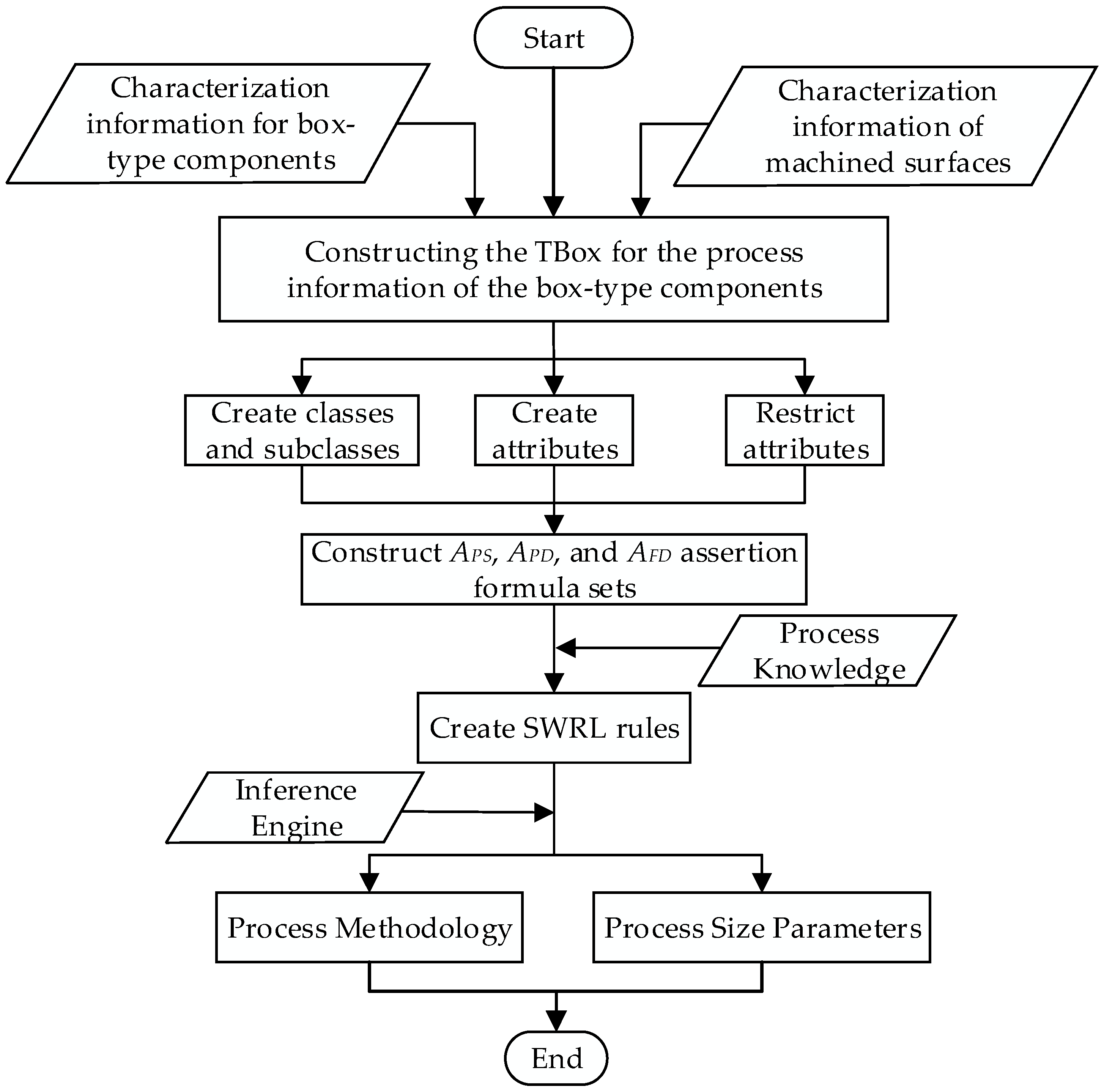
- (1)
- An information-processing TBox for the box-type components is constructed based on the material, production type, dimensions, and geometric tolerances of the box components and their machined faces.
- (2)
- The ontology model for the planar machining process decision-making of box-type components is developed. A hierarchical structure for the process decision classes is established based on the relevant terminology of process knowledge, and attributes are defined and constrained according to the relationships between the classes.
- (3)
- An assertion formula set is constructed. Based on the obtained feature information of the box-type component, assertion formula sets are created for the relationships between the component and its machined faces (APS), the component and its design features (APD), and the machined faces and their design features (AFD).
- (4)
- Based on the constructed assertion formula sets (APS, APD, and AFD) and the SWRL rules for planar machining process decision-making of box-type components, the ontology’s built-in reasoning engine is employed to infer and generate the machining methods and process dimension parameters for the planar machining of the box-type components.
6.2. Case Study
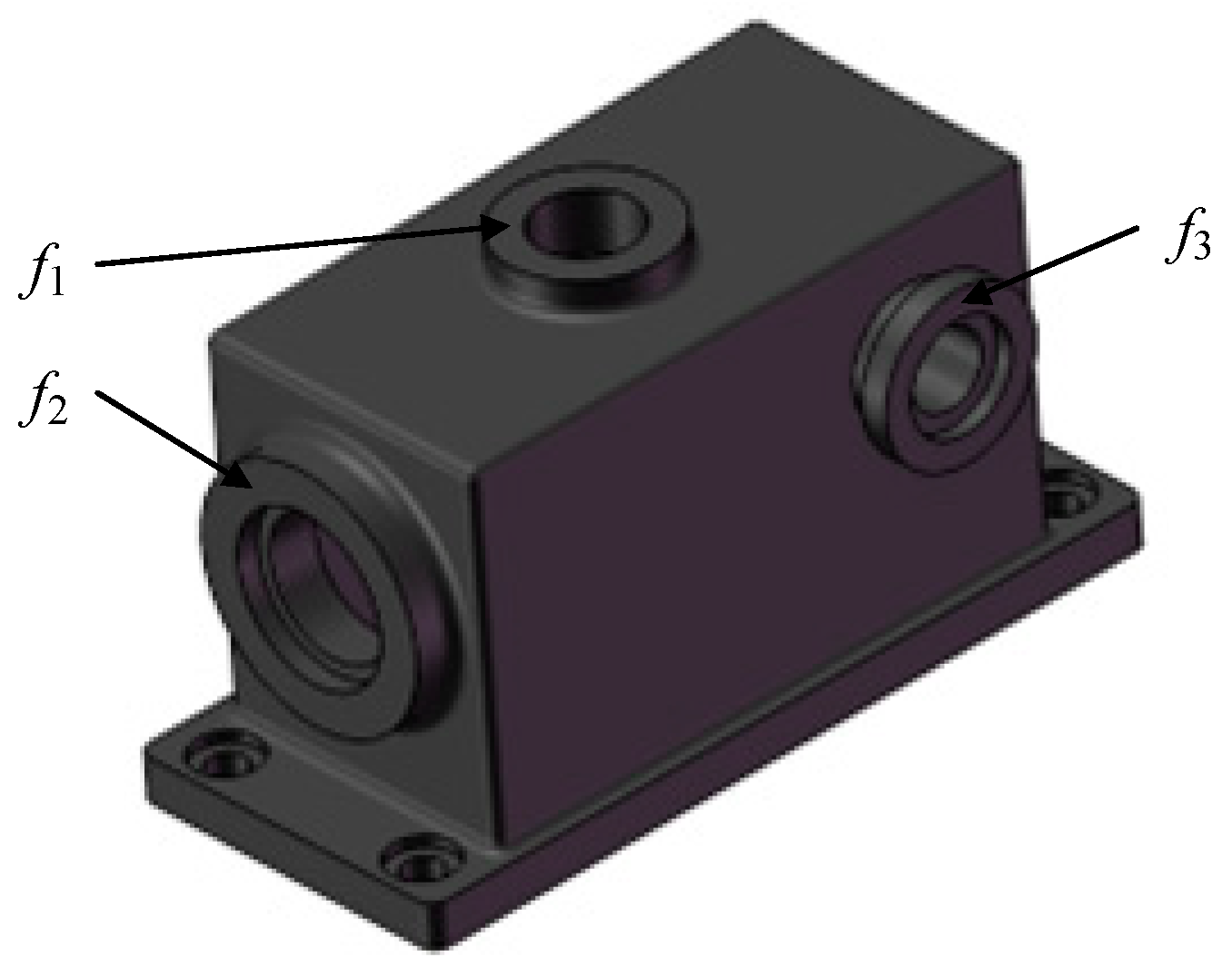
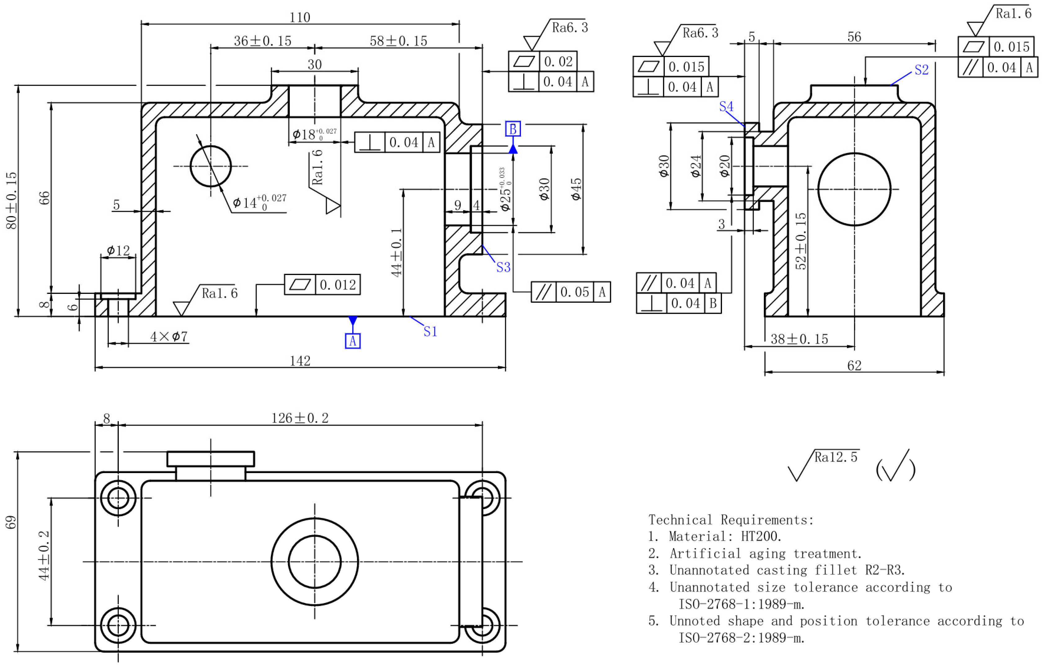
- A part model is constructed in the CAD system based on the design information, resulting in four machined faces (S1, S2, S3, and S4) for the box-type component. An assertion formula set (APS) is then constructed to represent the relationship between the part and its machined faces.APS = { MachinedFlat (S1), MachinedFlat (S2), MachinedFlat (S3), MachinedFlat (S4) }
- Extraction of Part-Related Design Feature Information. From Figure 9, the relevant part design feature information can be obtained: the heat treatment applied to the part is aging treatment, the material is HT200, and the production type is mass production. Based on this, an assertion formula set (APD) is constructed to represent the relationships between the part and its associated design features.APD = { Parts (CP), hasPT (Lb), isPMof (Gcr), isHTof (Na), isITof (f) }
- Extraction of Machined Surface-Related Design Feature Information. From Figure 5, the relevant machined surface design feature information can be obtained. Taking surface S1 as an example: basic dimension: 80 mm; length: 142 mm; width: 52 mm; accuracy class: grade 8; surface roughness: 1.6 μm; geometrical tolerance constraint: flatness. Other machined surfaces have similar characteristics. Based on this, an assertion formula set (AFD) is constructed to represent the relationships between the machined surface and its design features.AFD = {Value_Of_Ra (S1, 1.6), Value_Of_Ra (S2, 6.3), Value_Of_Ra (S3, 0.8), Value_Of_Ra (S4, 6.3), Value_Of_SBD (S1, 80), Value_Of_SBD (S2, 80), Value_Of_SBD (S3, 58), Value_Of_SBD (S4, 38), Value_SL (S1, 142), Value_SL (S2, 30), Value_SL (S3, 45), Value_SL (S4, 30), Value_SW (S1, 69), Value_SW (S2, 30), Value_SW (S3, 45), Value_SW (S4, 30), hasFPT(S1,FN), hasFPT(S2,PA), hasFPT (S3,SQ), hasFPT (S4,SQ), Value_TG(S1, 7), Value_ TG (S2, 8), Value_ TG (S3, 11), Value_ TG (S4, 11) }
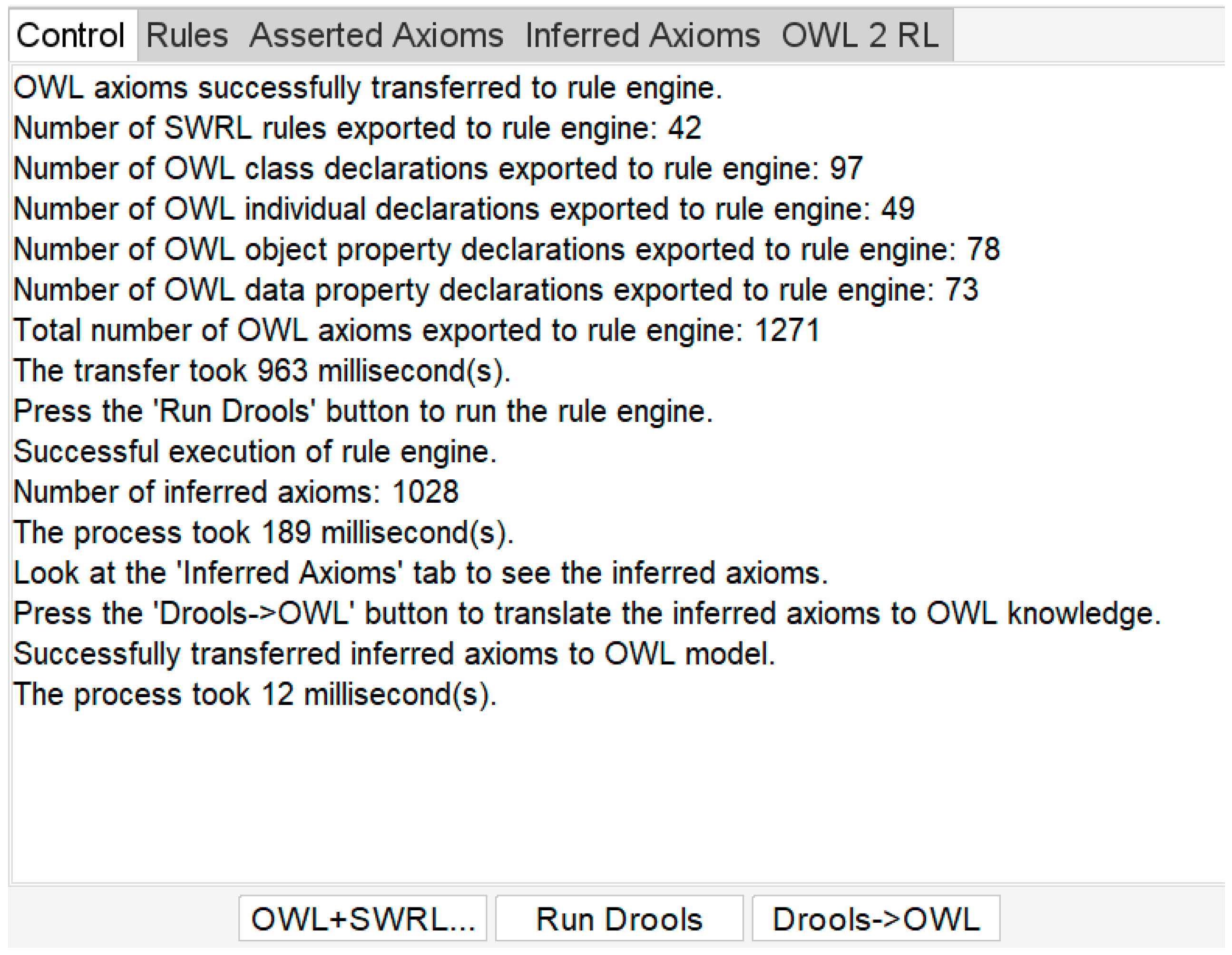
- The machining process information, machining scheme for the machined surface, and process dimension parameters for box-type parts are determined based on key attributes such as material, heat treatment, production type, and the machined surface characteristics, including dimensions, accuracy class, and geometrical tolerances. Utilizing this information, an ontology-based planar machining process model for box-type parts is developed, as illustrated in Figure 10. By constructing SWRL inference rules and integrating the assertion formula sets APS, APD, and AFD, the machining process information, machining scheme for the machined surface, and process dimension parameters are inferred, as shown in Figure 11. The results are systematically organized and presented in Table 6, Table 7 and Table 8. The inferred results align with those obtained using traditional methods, such as consulting relevant international standards and manual calculations [32,36].
7. Discussion
8. Conclusion and Future Work
Author Contributions
Funding
Institutional Review Board Statement
Informed Consent Statement
Data Availability Statement
Acknowledgments
Conflicts of Interest
References
- Su, Y.; Chu, X.; Chen, D.; Sun, X. A Genetic Algorithm for Operation Sequencing in CAPP Using Edge Selection Based Encoding Strategy. J. Intell. Manuf. 2018, 29, 313–332. [Google Scholar] [CrossRef]
- Liu, J.; Zhou, H.; Tian, G.; Liu, X.; Jing, X. Digital Twin-Based Process Reuse and Evaluation Approach for Smart Process Planning. Int. J. Adv. Manuf. Technol. 2019, 100, 1619–1634. [Google Scholar] [CrossRef]
- Deja, M.; Siemiatkowski, M.S. Machining Process Sequencing and Machine Assignment in Generative Feature-Based CAPP for Mill-Turn Parts. J. Manuf. Syst. 2018, 48, 49–62. [Google Scholar] [CrossRef]
- Duan, J.; Duan, Y. Toward a Framework of Extracting Typical Machining Process Routines Based on Knowledge Representation Learning. Adv. Eng. Inform. 2024, 60, 102431. [Google Scholar] [CrossRef]
- Leo Kumar, S.P.; Jerald, J.; Kumanan, S. An Intelligent Process Planning System for Micro Turn-Mill Parts. Int. J. Prod. Res. 2014, 52, 6052–6075. [Google Scholar] [CrossRef]
- Leo Kumar, S.P.; Jerald, J.; Kumanan, S. Feature-Based Modelling and Process Parameters Selection in a CAPP System for Prismatic Micro Parts. Int. J. Comput. Integr. Manuf. 2014, 28, 1046–1062. [Google Scholar] [CrossRef]
- Zai, D. Research on Key Technology of Feature-Based Three-Dimensional Process Design of Box-Like Parts. Master’s Thesis, Beijing Institute of Technology, Beijing, China, 2015. [Google Scholar]
- Zhu, H.; Li, J. Research on Three-Dimensional Digital Process Planning Based on MBD. Kybernetes 2018, 47, 816–830. [Google Scholar] [CrossRef]
- Wang, T.; Fang, L. Research on the Construction of Topological Ontology Model for Complex Mechanical Products. J. Mech. Electr. Eng. 2020, 37, 1121–1143. [Google Scholar]
- Zhao, Z.; Zhong, Y. Ontology construction and reasoning for product customization. J. Guilin Univ. Electron. Technol. 2017, 37, 483–489. [Google Scholar] [CrossRef]
- Rehage, G. Ontologie-Basiertes WBS Für Die Arbeitsplanung: Intelligente Wissensverwaltung Und Maschinenauswahl. In Intelligente Arbeitsvorbereitung auf Basis Virtueller Werkzeugmaschinen; Springer: Berlin/Heidelberg, Germany, 2019; pp. 41–90. [Google Scholar]
- Höfermann, H. Semantische Integration Der Disziplinübergreifenden Und Der Disziplinspezifischen Ebene in Der Entwicklung Intelligenter Technischer Systeme. In Tag des Systems Engineering 2024: Tagungsband Leipzig, 13.-15. November 2024; Gesellschaft fuer Systems Engineering: Bremen, Germany, 2024; Volume 22, p. 339. [Google Scholar]
- Podkolodnyy, N.; Podkolodnaya, O. Ontologies in Bioinformatics and Systems Biology. Russ. J. Genet. Appl. Res. 2016, 6, 749–758. [Google Scholar] [CrossRef]
- Manzoor, S.; Rocha, Y.G.; Joo, S.-H.; Bae, S.-H.; Kim, E.-J.; Joo, K.-J.; Kuc, T.-Y. Ontology-Based Knowledge Representation in Robotic Systems: A Survey Oriented toward Applications. Appl. Sci. 2021, 11, 4324. [Google Scholar] [CrossRef]
- Koper, R. Current Research in Learning Design. J. Educ. Technol. Soc. 2006, 9, 13–22. [Google Scholar]
- Liu, H.; Du, J. Semantic Modeling of Manufacturing Domain Knowledge Based on Multidimensional Ontology. Manuf. Technol. Mach. Tools 2019, 9, 140–146. [Google Scholar]
- Zhong, Y.; Lu, H. Construction of a Comprehensive Domain Ontology Knowledge Base for Assembly Tolerance. Comput. Eng. Sci. 2016, 38, 1413. [Google Scholar]
- Yu, M.; Tianlong, G.; Liang, C.; Fengying, L. Assembly Ontology for Assembly Sequence Planning. Int. J. Pattern Recognit. Artif. Intell. 2016, 29, 203–215. [Google Scholar]
- Chen, S.; Yi, J.; Jiang, H.; Zhu, X. Ontology and CBR Based Automated Decision-Making Method for the Disassembly of Mechanical Products. Adv. Eng. Inform. 2016, 30, 564–584. [Google Scholar]
- Peng, Z.; Huang, M.; Zhong, Y.; Tang, Z. Construction of Ontology for Auto-Interpretable Tolerance Semantics in Skin Model. J. Ambient. Intell. Humaniz. Comput. 2020, 11, 3545–3558. [Google Scholar] [CrossRef]
- Shi, X.; Tian, X.; Wang, G.; Zhang, M.; Zhao, D. A Simplified Model for Assembly Precision Information of Complex Products Based on Tolerance Semantic Relations. Sustainability 2018, 10, 4482. [Google Scholar] [CrossRef]
- He, Y.; Hao, C.; Wang, Y.; Li, Y.; Wang, Y.; Huang, L.; Tian, X. An Ontology-Based Method of Knowledge Modelling for Remanufacturing Process Planning. J. Clean. Prod. 2020, 258, 120952. [Google Scholar] [CrossRef]
- Wang, J.; Huang, M. Ontology-Based Method for Automatic Generation of Dimensional Parameters of Cylindrical Process for Shaft Parts. J. Guilin Univ. Electron. Sci. Technol. 2022, 42, 468–475. [Google Scholar]
- Zhang, C. A Study of Formal Description and Retrieval of Artifacts Based on Domain Ontology. Master’s Thesis, Kunming University of Science and Technology, Kunming, China, 2018. [Google Scholar]
- Horrocks, I.; Kutz, O.; Sattler, U. The Even More Irresistible SROIQ. Kr 2006, 6, 57–67. [Google Scholar]
- Li, Y.; Zhang, Z. Research on Domain Ontology Construction Method. Comput. Eng. Sci. 2008, 30, 129. [Google Scholar]
- Fernández-López, M.; Gómez-Pérez, A. Overview and Analysis of Methodologies for Building Ontologies. Knowl. Eng. Rev. 2002, 17, 129–156. [Google Scholar] [CrossRef]
- Youn, S.; McLeod, D. Ontology Development Tools for Ontology-Based Knowledge Management. In Encyclopedia of E-Commerce, E-Government, and Mobile Commerce; IGI Global: Hershey, PA, USA, 2006; pp. 858–864. [Google Scholar]
- Fraga, A.L.; Vegetti, M.; Leone, H.P. Ontology-Based Solutions for Interoperability among Product Lifecycle Management Systems: A Systematic Literature Review. J. Ind. Inf. Integr. 2020, 20, 100176. [Google Scholar]
- Horrocks, I.; Patel-Schneider, P.F.; Boley, H.; Tabet, S.; Grosof, B.; Dean, M. SWRL: A Semantic Web Rule Language Combining OWL and RuleML. W3C Memb. Submiss. 2004, 21, 1–31. [Google Scholar]
- Ji, Z. Analyzing the Principle of Machining Process Design of Parts. Ind. Des. 2015, 117. [Google Scholar]
- Chen, H. Handbook of Practical Machining Processes, 4th ed.; Machinery Industry Press: Beijing, China, 2016. [Google Scholar]
- Song, F. Design method of plane blank size basedon reference vector. Master’s Thesis, Taiyuan University of Technology, Taiyuan, China, 2018. [Google Scholar]
- Qin, Y.; Jiang, C.; Huana, M. Automatic Generation of Assembly Sequence Based on Ontology. Comput. Integr. Manuf. Syst. 2018, 24, 1345. [Google Scholar]
- Bravo, M.; Hoyos Reyes, L.F.; Reyes Ortiz, J.A. Methodology for Ontology Design and Construction. Contaduría Y Adm. 2019, 64, 134. [Google Scholar] [CrossRef]
- Zhang, B. Typical Precision Parts Machining Process Analysis and Examples; Mechanical Industry Press: Beijing, China, 2017. [Google Scholar]


| Serial Number | Machining Program | Accuracy Grade | Surface Roughness | Applicable Range |
|---|---|---|---|---|
| CMP1 | Rough Milling | IT11~IT13 | 12.5~6.3 | Flat surface machining without hardening |
| CMP2 | Rough Milling→Semi-finish Milling | IT8~IT11 | 12.5~3.2 | |
| CMP3 | Rough Milling→Finish Milling | IT7~IT9 | 6.3~1.6 | |
| CMP4 | Rough Milling→Semi-finish Milling →Finish Milling | IT6~IT8 | 3.2~0.63 | |
| CMP5 | Rough Milling→Finish Milling →Grinding | IT6~IT7 | 0.8~0.2 | Hardened or unhardened ferrous metal workpieces |
| CMP6 | Rough Milling→Semi-finish Milling —Finish Milling→Grinding | IT5~IT6 | 0.4~0.2 | |
| CMP7 | Rough Milling→Finish Milling→Scraping | IT5~IT6 | 0.8~0.1 | |
| CMP8 | Rough Milling→Semi-finish Milling →Finish Milling→Scraping | IT5~IT6 | 0.8~0.04 | |
| … | … | … | … | … |
| Processing Program | Accuracy Class of Straightness and Flatness | |||||||||||
|---|---|---|---|---|---|---|---|---|---|---|---|---|
| 1 | 2 | 3 | 4 | 5 | 6 | 7 | 8 | 9 | 10 | 11 | 12 | |
| CMP1 | ● | ● | ||||||||||
| CMP2 | ● | ● | ||||||||||
| CMP3 | ● | ● | ||||||||||
| CMP4 | ● | ● | ● | |||||||||
| CMP5 | ● | ● | ● | ● | ||||||||
| CMP6 | ● | ● | ● | |||||||||
| CMP7 | ● | ● | ||||||||||
| CMP8 | ● | ● | ||||||||||
| Processing Program | Parallelism and Perpendicularity Accuracy Class | |||||||||||
|---|---|---|---|---|---|---|---|---|---|---|---|---|
| 1 | 2 | 3 | 4 | 5 | 6 | 7 | 8 | 9 | 10 | 11 | 12 | |
| Plane to Plane | ||||||||||||
| CMP1 | ● | ● | ||||||||||
| CMP2 | ● | ● | ● | |||||||||
| CMP4 | ● | ● | ● | |||||||||
| CMP5 | ● | ● | ● | ● | ● | ● | ||||||
| CMP8 | ● | ● | ● | ● | ● | |||||||
| Axis to Axis (or Plane) | ||||||||||||
| CMP1 | ● | ● | ||||||||||
| CMP2 | ● | ● | ● | |||||||||
| CMP4 | ● | ● | ● | |||||||||
| CMP5 | ● | ● | ● | ● | ● | |||||||
| Terminology Category | Terminology Content | |
|---|---|---|
| Terminology Related to Planar Machining Process Decisions | Terms Related to Design Features | Production Type, Heat Treatment, Casting Method, Part Material, Nominal Size, Nominal Size Tolerance, Economic Accuracy Class, Surface Roughness, Geometric Tolerance Constraints, Geometric Tolerance Class, Locating Datum |
| Terminology Related to Machining Solutions | Planar Machining Methods, Planar Machining Solutions | |
| Terminology Related to Process Parameters | Tolerance Class of Blank Dimensions, Tolerance Class of Blank Allowance, Process Dimensions, Tolerance of Process Dimensions, Tolerance Class of Process Dimensions, Process Allowance, Total Machining Allowance, Tolerance Zone Dimensions |
| Properties | Domain | Range |
|---|---|---|
| hasFD | MachinedFlat | FDatum |
| hasPT | Part | PType |
| isCMof | MachinedFlat | CMethod |
| hasCMP | MachinedFlat | FlatMP |
| isHTof | Part | HTreat |
| Value_Ra | MachinedFlat | Float |
| Value_DTG | Part | Int |
| Value_FMA | MachinedFlat | Float |
| Value_SBD | MachinedFlat | Float |
| Value_TMA | MachinedFlat | Float |
| Value_RMD | MachinedFlat | Float |
| Production Type | Part Material | Heat Treatment | Casting Method | Machining Allowance Grade | Tolerance Grade of Blank Dimensions |
|---|---|---|---|---|---|
| Large Quantities | HT200 | Aging Treatment | Machine Molding of Sand Casting | 10 | G |
| Machined Surface. | Rough Reference | Fine Reference |
|---|---|---|
| S1 | Φ25 Hole and Plane S2 | |
| S2 | Plane S1 | Φ25 Hole and Plane S1 |
| S3 | Φ18 Hole | Φ18 Hole and Plane S1 |
| S3 | Φ18 Hole | Φ18 Hole and Plane S1 |
| Machined Surface | Blank Dimensions | Machining Plan and Process Dimension Parameters | Process Allowance | Total Machining Allowance | Reference System | ||||
|---|---|---|---|---|---|---|---|---|---|
| Rough Milling | Semi-Finish Milling | Finish Milling | Rough Milling | Semi-Finish Milling | Finish Milling | ||||
| S1 | 83.5 ± 1.6 | 81.3 ± 0.8 | 80.3 ± 0.3 | 80.0 ± 0.15 | 2.2 | 1.0 | 0.3 | 3.5 | Plane S2 |
| S2 | 83.5 ± 1.6 | 81.3 ± 0.8 | 80.3 ± 0.3 | 80.0 ± 0.15 | 2.2 | 1.0 | 0.3 | 3.5 | Plane S1 |
| S3 | 61.5 ± 1.4 | 59.3 ± 0.3 | 58.0 ± 0.15 | 2.2 | 1.3 | 3.5 | Φ18Hole axis | ||
| S4 | 41.5 ± 1.3 | 39.3 ± 0.3 | 38 ± 0.15 | 2.2 | 1.3 | 3.5 | Φ18Hole axis | ||
Disclaimer/Publisher’s Note: The statements, opinions and data contained in all publications are solely those of the individual author(s) and contributor(s) and not of MDPI and/or the editor(s). MDPI and/or the editor(s) disclaim responsibility for any injury to people or property resulting from any ideas, methods, instructions or products referred to in the content. |
© 2025 by the authors. Licensee MDPI, Basel, Switzerland. This article is an open access article distributed under the terms and conditions of the Creative Commons Attribution (CC BY) license (https://creativecommons.org/licenses/by/4.0/).
Share and Cite
Shi, Z.; Huang, M.; Tang, Z.; Hu, Z.; Hu, W. A Process Decision-Making Method for Planar Machining of Box-Type Components. Appl. Sci. 2025, 15, 4029. https://doi.org/10.3390/app15074029
Shi Z, Huang M, Tang Z, Hu Z, Hu W. A Process Decision-Making Method for Planar Machining of Box-Type Components. Applied Sciences. 2025; 15(7):4029. https://doi.org/10.3390/app15074029
Chicago/Turabian StyleShi, Zhongkun, Meifa Huang, Zhemin Tang, Zecheng Hu, and Weihao Hu. 2025. "A Process Decision-Making Method for Planar Machining of Box-Type Components" Applied Sciences 15, no. 7: 4029. https://doi.org/10.3390/app15074029
APA StyleShi, Z., Huang, M., Tang, Z., Hu, Z., & Hu, W. (2025). A Process Decision-Making Method for Planar Machining of Box-Type Components. Applied Sciences, 15(7), 4029. https://doi.org/10.3390/app15074029