Article

Experimental and Numerical Investigation of Vibration-Suppression Efficacy in Spring Pendulum Pounding-Tuned Mass Damper

1
Department of Road and Bridge Engineering, Liaoning Provincial College of Communications, Shenyang 110168, China
2
Liaoning Urban and Rural Construction Planning Design Institute Co., Ltd., Shenyang 110006, China
3
State Laboratory of Coastal and Offshore Engineering, Faculty of Infrastructure Engineering, Dalian University of Technology, Dalian 116024, China
4
School of Civil Engineering, Shenyang Jianzhu University, Shenyang 110168, China
*
Author to whom correspondence should be addressed.
Appl. Sci. 2025, 15(8), 4297; https://doi.org/10.3390/app15084297
Submission received: 24 February 2025 / Revised: 30 March 2025 / Accepted: 7 April 2025 / Published: 13 April 2025

Abstract

:
Originally proposed by the authors, the spring pendulum pounding-tuned mass damper (SPPTMD)—a novel nonlinear damping system comprising a spring pendulum (SP) and motion limiter that dissipates energy through spring resonance amplification and controlled mass-limiter impacts—was theoretically validated for structural vibration control. To experimentally verify its efficacy, a two-story, lightly damped steel frame was subjected to sinusoidal excitation and historical earthquake excitations under both uncontrolled and SPPTMD-controlled conditions. The results demonstrated (1) significant vibration attenuation through SPPTMD implementation and (2) enhanced control effectiveness in soft soil environments compared to stiff soil conditions. Additionally, a numerical model of the SPPTMD–structure system was developed, with computational results showing excellent correlation to experimental data, thereby confirming modeling accuracy.

1. Introduction

Tall and flexible structures, such as offshore wind turbines, chimneys, and transmission towers, are characterized by high flexibility and low damping. Consequently, these structures suffer from excessive vibrations under wind loads or earthquakes and in some extreme cases may even collapse. Therefore, reducing the vibration of these structures can effectively improve their safety and reliability.
There are two main types of dampers used for vibration reduction in tall flexible structures, namely energy dissipation dampers (e.g., metallic energy-dissipation dampers [1,2,3], viscous dampers [4,5,6], friction dampers [7,8,9], and magnetorheological dampers [10,11,12]) and linear dynamic vibration absorbers (e.g., suspended mass pendulums (SMP) [13,14] and tuned mass dampers (TMDs) [15,16]). Linear dynamic vibration absorbers are widely used in structural vibration control due to their simple structure and ease of installation. To improve their vibration-reduction performance, various forms of nonlinear energy-dissipation components (e.g., pounding components [17,18,19], internal resonance components [20,21], and shape memory alloys [22,23,24]) have been introduced to effectively increase the energy-dissipation capacity of dampers.
As a typical nonlinear damper, a pounding-tuned mass damper (PTMD) outperforms a TMD in terms of vibration-reduction effect [25,26] and is robust against the de-tuning effect [27,28]. Song et al. [29] installed a PTMD in a pipeline structure and showed that the PTMD effectively reduced the vibration in the pipeline and improved the damping ratio of the structure. Yang et al. [30] experimentally investigated the vibration control ability of PTMDs for underwater structures, demonstrating that PTMDs remained significantly effective under submerged conditions. Lin et al. [31] studied the vibration control of a TV tower with a PTMD. Fu et al. [32] applied a pounding spacer damper (PSD) to the wind-induced vibration control of transmission towers. Yin et al. [33] showed through numerical simulation that PTMDs could effectively reduce bridge deck vibrations induced by moving vehicles. Wang et al. [34] proposed a single-sided PTMD for controlling vortex-induced bridge deck vibrations and experimentally verified its vibration-reduction effect. Lin et al. [35] and Yin et al. [36] investigated the suppression of structural vibration with multiple PTMDs. Tan et al. [37] experimentally verified the vibration-reduction performance of a spring steel-type PTMD and a simple pendulum-type PTMD. Liu et al. [38] carried out wind tunnel tests to verify the good suppression effect of PTMDs on the multimode vortex-induced vibration of stay cables. Tian et al. [39] proposed a bidirectional PTMD for vibration reduction in transmission towers. Ghasemi et al. [40] applied a PTMD with a shape memory alloy to the vibration control of an offshore jacket platform. Zhao et al. [41] designed a PTMD for cantilevered traffic signal structures and verified its effectiveness through experiments and numerical simulations. Duan et al. [42] proposed a PTMD installed in a confined space and demonstrated its robustness. Wang et al. [43,44] verified the vibration control performance of a pendulum PTMD (PPTMD).
A spring pendulum (SP) is a nonlinear damper composed of a mass block attached to the free end of a spring [45,46]. It has two characteristic frequencies, i.e., the frequency of the vibration mode along the radial direction of the spring and the frequency of the swing mode in the tangential direction [47,48]. Energy is transferred between the two modes when their frequencies satisfy the internal resonance condition [49,50]. A previous study on internal resonance springs [21] verified that an SP can effectively control the vibration of a structure. However, an SP lacks dedicated damping components, resulting in constrained energy dissipation capacity. To address this limitation, a spring pendulum pounding-tuned mass damper (SPPTMD) that integrates an SP with a limiter is proposed. This configuration synergistically harnesses spring resonance energy transfer and mass block impacts to achieve enhanced vibration-suppression performance.
In our previous work, a numerical model of the structure–SPPTMD system was derived to enable a numerical study of its vibration control performance, in which the SPPTMD was proven to be more effective than the traditional SMP and SP [51]. However, the effectiveness of the vibration-reduction effect of the SPPTMD has not been verified experimentally. Therefore, in this study, an experiment was conducted on a two-story frame support structure with and without the SPPTMD. The vibration reductions for the SPPTMD-controlled test model under sinusoidal excitation, white noise excitation, and various seismic waves were calculated, and the vibration control effect of the SPPTMD under different site classes was analyzed. The article is organized as follows. Section 2 introduces the mechanical model of the SPPTMD, the experimental setup is described in Section 3, followed by the analysis of experimental results in Section 4, and Section 5 summarizes the article with the conclusions.

2. Mechanism of SPPTMD and Numerical Model of Structure–SPPTMD System

2.1. Mechanism of the SP

Since the SPPTMD consists of an SP and a motion limiter, it is necessary to understand the mechanism of an SP. The SP, which is a mass suspended by a spring, has two vibration modes, i.e., a radial vibration mode and a swing vibration mode (Figure 1 [51]). The circular frequencies of the two vibration modes are given as follows:
ω s = k s m d ,
ω p = g l o ,
where ω s is the circular frequency of the radial vibration, k s is the stiffness of the spring, m d is the mass of the mass block, ω p is the circular frequency of the swing vibration, g = 9 . 8   m / s 2 is the acceleration of gravity, and l o is the length of the spring under gravity:
l o = g 2 π f 2 ,
where f is the frequency of the main structure.
A previous study found that when the ratio of ω s to ω p is close to 2, energy is transferred between the two vibration modes, a phenomenon called internal resonance [46]. The SP relies on internal resonance to transfer the kinetic energy absorbed by the damper from the swing mode to the vibration mode, thereby increasing the vibration absorption capacity of the damper.

2.2. Mechanism of the SPPTMD

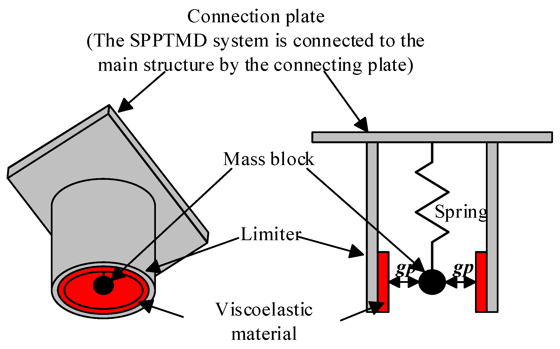
Even though the SP amplifies the vibration absorbing ability by introducing the internal phenomenon, its energy dissipation is still limited. Therefore, in this paper, the impact damping is introduced to the damper to develop a novel damping device, namely the SPPTMD. As shown in Figure 2 [51], the SPPTMD is composed of a connection plate, a spring, a mass block, and an annular limiter embedded with viscoelastic material. The damper is connected to the controlled structure via the connection plate. The spring forms a spring pendulum system by attaching one end to the connection plate and the other end to the mass block. The SPPTMD is essentially an SP with an additional limiter, and it is a nonlinear vibration absorber that relies on the SP and the pounding of the additional mass with the limiter to dissipate energy. When the structure vibrates with a small amplitude, there is no pounding of the additional mass with the limiter, and the SPPTMD functions as an SP that suppresses structural oscillations through both the inertial force generated by the viscoelastic damper and the internal resonance mechanism of the spring system; when the structure vibrates with a relatively large amplitude, the pounding of the additional mass with the limiter occurs, and the SPPTMD dissipates the kinetic energy of the system absorbed by the damper through the pounding.

2.3. Numerical Model of the Structure–SPPTMD System

Assuming that an SPPTMD is attached to the ith degree of freedom (DOF) of an n-DOF system (Figure 3 [51]), the equation of motion of the structure–SPPTMD system is as follows:
M s x ¨ t + C s x ˙ t + K s x t = M s I x ¨ g ( t ) + L F s , x ( t ) + F d i r L F c , x ( t ) m d x ¨ d ( t ) = m d x ¨ g ( t ) F s , x ( t ) F d i r F c , x ( t ) m d y ¨ d ( t ) = m d g F s , y ( t ) F c , y ( t ) ,
where M s , C s , and K s are the mass matrix, damping matrix, and stiffness matrix of the uncontrolled structure, respectively; x ¨ ( t ) , x ˙ ( t ) , and x ( t ) are the acceleration vector, velocity vector, and displacement vector of the uncontrolled structure, respectively; I is a column vector of 1s; x ¨ g is the ground acceleration; L is the position vector of the SPPTMD; F s , x and F c , x are the restoring force and the pounding force, respectively, of the additional mass in the x-direction; F d i r is the direction of the pounding force; m d is the additional mass; x d and y d are the displacements of the mass block in the horizontal and vertical directions, respectively; F s , y and F c , y are the restoring force and pounding force, respectively, of the additional mass in the y-direction. The position vector L of the SPPTMD can be written as follows:
L = 0 , 0 , , 1 the   i th   element   equals   one , 0 , , 0 T ,
The circular shape of the limiter allows the pounding to occur on both the left and right sides. The pounding force direction F d i r is expressed as follows:
F d i r = 1                 x d x i > g p                   pounding   on   the   right   side 1           x d x i < g p             pounding   on   the   left   side 0                         others                           not   pounding   ,
According to our previous study, the restoring force and pounding force are obtained as follows:
F s , x = k s x r ( 1 l o r i x r 2 + y d + l o 2 ) F s , y = k s y d + l o ( 1 l o r i x r 2 + y d + l o 2 ) ,
x r = x d x i ,
l o r i = l o m d g k s ,
where k s is the stiffness of the spring, x i is the horizontal displacement of the ith DOF of the uncontrolled structure, and l o r i is the original length of the spring.
According to the Hertz contact force model, the pounding force of the SPPTMD is obtained as follows:
F c = β δ 1.5 + c δ β δ 1.5   if   δ ˙ > 0   if   δ ˙ < 0 ,
where β is the pounding stiffness, δ is the relative deformation of the viscoelastic material, and c is the pounding damping. δ and c can be calculated by the following two equations:
δ = x r g p     if   the   right   boundary   is   impacted x r + g p     if   the   left   boundary   is   impacted ,
c = 2 ξ β m d m i m d + m i δ ,
where g p is the gap between the mass block and the limiter; ξ is the pounding damping ratio; m d and m i are the masses of the SPPTMD and the ith story, respectively. ξ can be calculated as follows:
ξ = 9 5 2 1 e 2 e e 9 π 16 + 16 ,
where e = h h is the coefficient of restitution, which can be determined with a ball-drop experiment by dropping a ball in free fall at a height of h and measuring its rebound height of h .
The calculation model in Equation (4) was established in the Simulink environment of MATLAB R2013a.

3. Experimental Model and Setups

A two-story steel frame structure with a total mass of 8.84 kg was developed for experimental investigation. The system demonstrated a fundamental natural frequency of 1.5 Hz, derived from fast Fourier transform (FFT) analysis of free vibration response data. The SPPTMD designed for vibration suppression in the model features a mass ratio of 3.4%, a spring stiffness of 80.12 N/m, and a pendulum length of 0.11 m, as determined through numerical calculations. The impact stiffness of the SPPTMD in this study adopts the experimentally validated value k h = 1.7 × 10 4 N / m 3 / 2 , derived from Zhang et al.’s investigations [25] on viscoelastic materials, thereby ensuring consistency between numerical modeling and empirical data while maintaining parametric fidelity.
The motion limiter consisted of a polyvinyl chloride (PVC) pipe internally clad with viscoelastic damping material, maintaining a 7.5 mm operational gap between the auxiliary mass and limiter surfaces (Figure 4). The SPPTMD assembly was rigidly affixed to the upper floor slab via bolted connections.
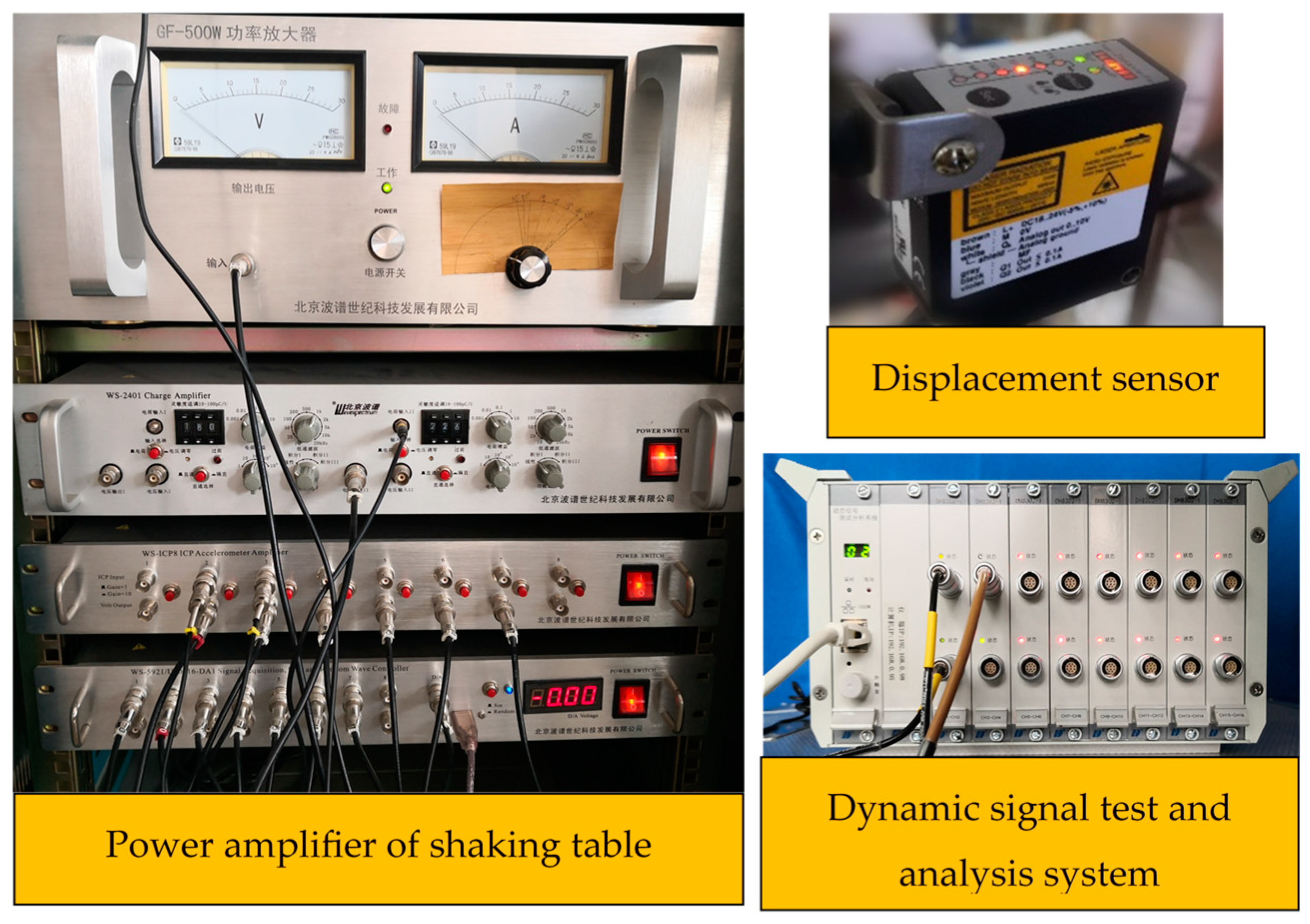
The sinusoidal excitation and historical earthquake excitation were administered using a shaking table (Wavespectrum Century Technology, Beijing, China). Structural responses were monitored using a high-precision OPTEX laser displacement transducer (OPTEX, Otsu, Japan), with data acquisition performed by a dynamic signal test-analysis system (Donghua Testing Technology, Taizhou, China). The complete experimental arrangement is schematically illustrated in Figure 5.

4. Experimental Results

To assess the vibration mitigation performance of the SPPTMD under various loading conditions, the displacement peak vibration-reduction rate η d and the displacement root mean square (RMS) vibration-reduction rate η R M S are defined as follows:
η d = D 0 D 1 D 0 × 100 % ,
η R M S = A 0 A 1 A 0 × 100 % ,
where D 0 and D 1 are the displacements of the uncontrolled and controlled models, respectively, and A 0 and A 1 are the root-mean-square (RMS) displacements of the uncontrolled and controlled models, respectively.

4.1. Free Vibration Case

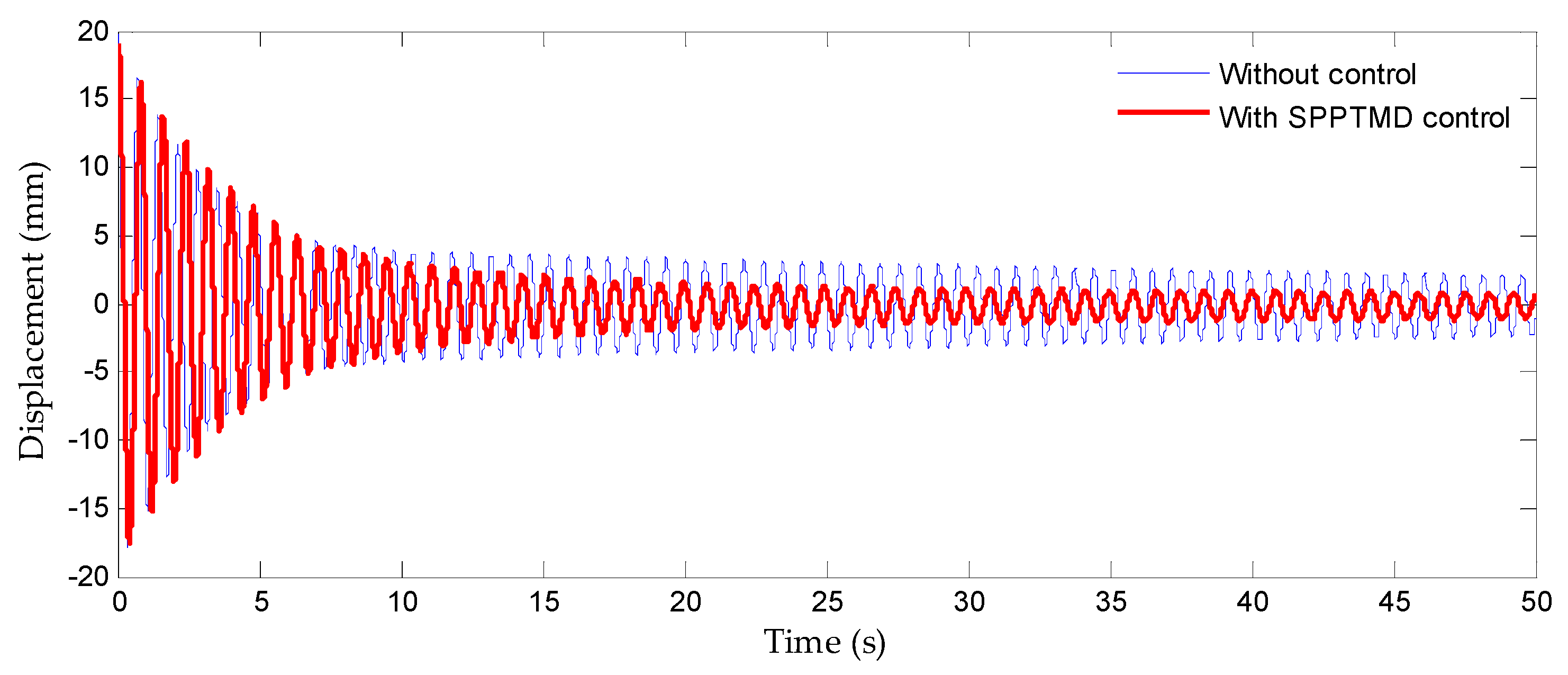
Under this loading condition, a 20 mm initial displacement was imposed on the model, with its free vibration response captured as illustrated in Figure 6. Analytical results demonstrated that the SPPTMD significantly reduced the displacement response of the model under free vibration conditions. The SPPTMD responded rapidly, being activated almost instantaneously with vibration initiation. By 8.5 s into the vibration, a 50% vibration-reduction rate was achieved. At 14.5 s, the SPPTMD-controlled model exhibited a displacement of 1.00 mm with a 71.7% vibration-reduction rate. Furthermore, the damper reduced the model’s settling time (defined as the duration required for displacement to decay to 5% of the initial value) from 102 s in the uncontrolled state to 14.5 s, representing an 85.8% vibration-reduction rate. These findings conclusively demonstrate the efficacy of the SPPTMD in suppressing structural free vibrations.

4.2. Resonant Vibration Case

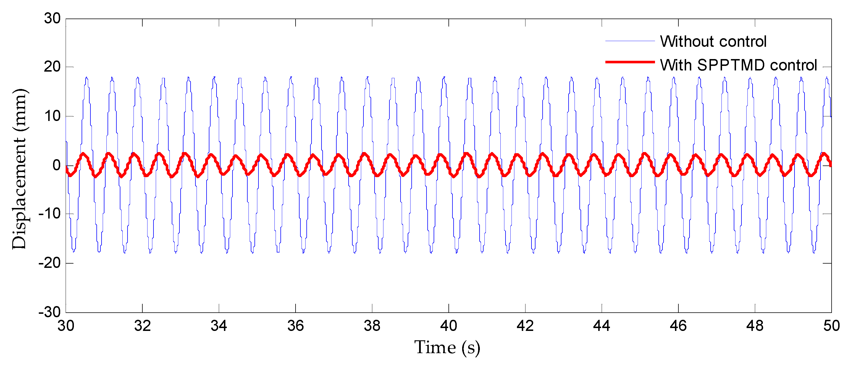
Resonant vibration excitation (f = 1.5 Hz; T = 50 s) was applied to the model, where the excitation frequency matched the model’s fundamental natural frequency, and the displacement responses under resonant conditions were recorded in Figure 7. The results demonstrate that the peak displacements under uncontrolled and controlled states reached 18.00 mm and 2.5 mm, respectively, achieving an 86.13% vibration-reduction rate. This conclusively verifies the SPPD’s effectiveness in suppressing structural resonant responses.

4.3. Forced Vibration Response Under Variable Excitation Frequencies

The comparative displacement responses of the experimental model under sinusoidal excitations with varying frequencies are presented in Figure 8, with corresponding vibration-reduction rates summarized in Table 1. Implementation of the SPPTMD control system significantly attenuated structural displacement responses while demonstrating robust vibration suppression across a broad frequency range. At the resonant frequency of 1.5 Hz, maximum vibration-reduction rates of 86.13% for peak displacement and 87.88% for RMS displacement were achieved. As excitation frequencies deviated from the structural natural frequency, the control efficacy gradually decreased yet maintained notable reductions of 33.87% (peak) and 31.89% (RMS). These results conclusively demonstrate the SPPTD’s effectiveness in vibration mitigation regardless of excitation frequency variations.

4.4. Earthquake Excitation Case

To investigate the seismic control performance of the SPPTMD for structures in site classes I–IV, three seismic records per site class were selected. For each class, one record was utilized for both shaking-table tests and numerical simulations, while two additional records were used exclusively for simulations, and the seismic record parameters are detailed in Table 2. During the loading process, the peak ground acceleration (PGA) was amplitude-adjusted to 50 gal, corresponding to the peak acceleration of a moderate-intensity earthquake with seismic intensity VI.

4.4.1. Vibration-Suppression Effectiveness

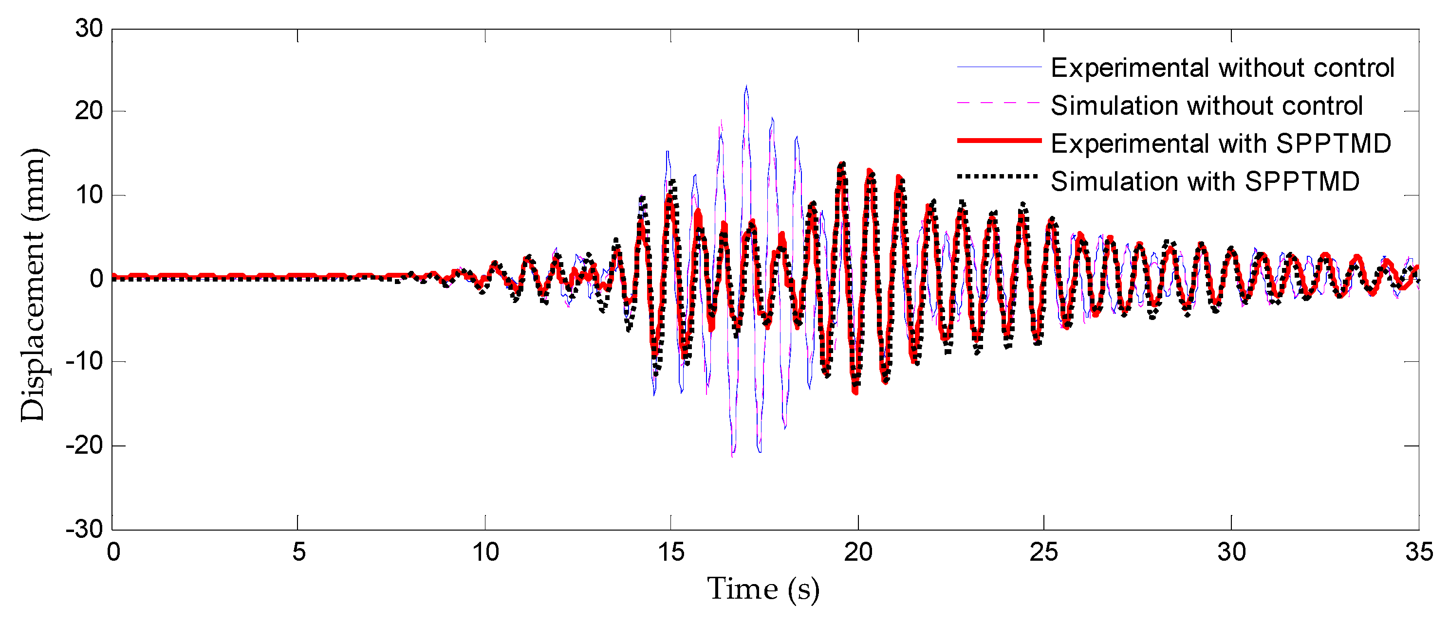
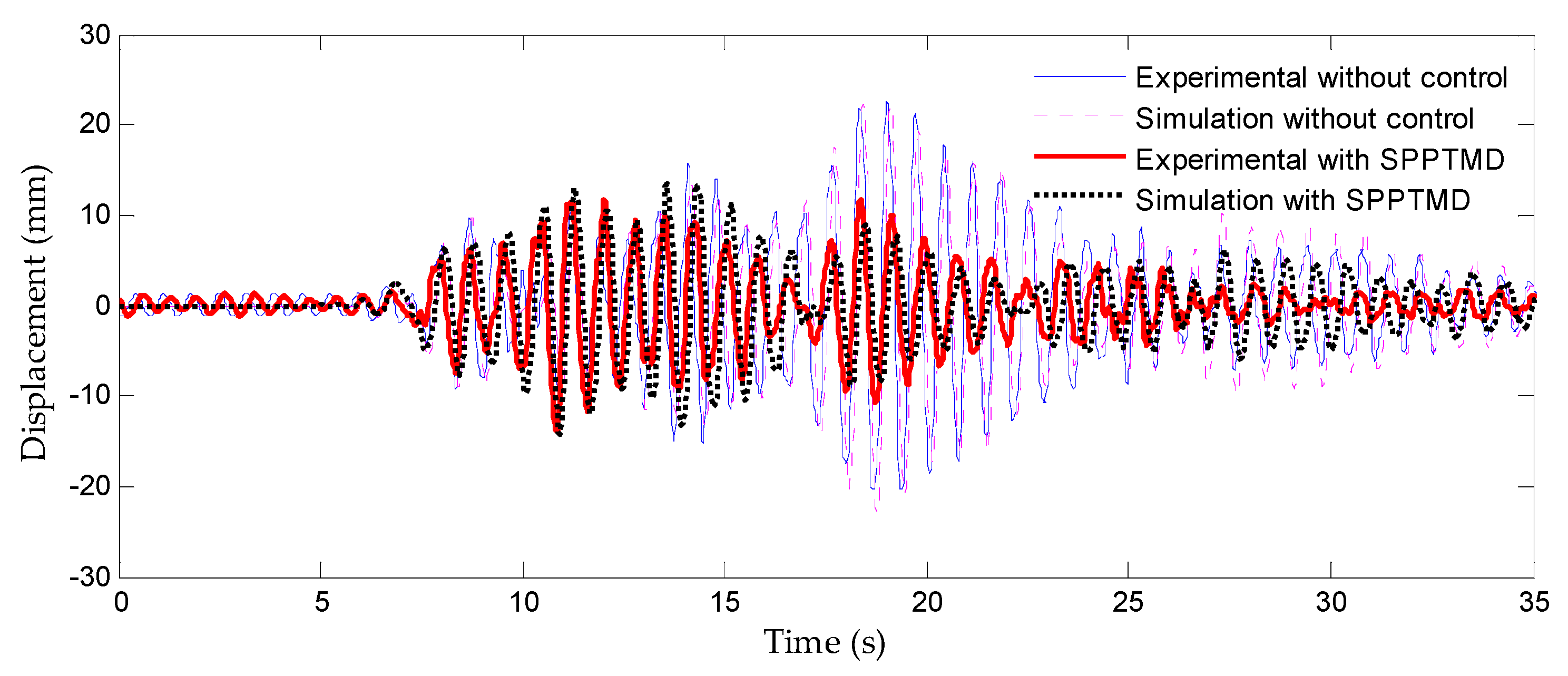
Given the extensive dataset (12 seismic records), displacement responses under four representative seismic waves are plotted in Figure 9, Figure 10, Figure 11 and Figure 12, with peak response values and RMS vibration-reduction rates summarized in Table 3. The experimental data demonstrate that the SPPTMD effectively mitigates structural displacement responses under seismic loading, achieving peak and RMS vibration-reduction rates of 60.25% and 58.35%, respectively. The results further indicate that the vibration control efficiency will increase when the ground is softer. For instance, the average peak vibration-reduction rate of the three earthquakes in venue class I is 42.9%, whereas that of venue classes II, III, and IV are 44.06%, 45.15%, and 50.27%, respectively. Similarly, the average RMS vibration-reduction rate increased from 36.06% (class I) to 36.60% (class II), 44.45% (class III), and 56.78% (class IV), with all indicating that the vibration control performance of the SPPTMD increased with increasing venue class.

4.4.2. Validation of Numerical Model

As the proposed SPPTD constitutes a nonlinear control device, its mathematical modeling poses challenges for general-purpose FEM software. Consequently, a MATLAB R2013a-based simulation framework was developed to numerically analyze the coupled dynamics of the controlled structure–SPPTD system. Numerical model validation was conducted through comparisons between experimental data and numerical results.
As summarized in Table 4, maximum displacement discrepancies between experimental and numerical results remain within acceptable margins: error ranges for uncontrolled and SPPTD-controlled cases were 1.00–5.36% (min–max) and 2.07–9.99% (min–max), respectively. Furthermore, Figure 9, Figure 10, Figure 11 and Figure 12 demonstrate a close agreement between shake-table testing and numerical simulation results regarding the displacement responses of the controlled model. The numerical results consistently exhibit minor overestimations compared to the experimental data, and this characteristic enhances the damper’s operational reliability in practical applications. These results confirm that the proposed impact force model and numerical simulation framework accurately predict structural dynamic responses under SPPTMD control.

5. Conclusions

This study proposed a novel type of energy-dissipation damper incorporating a viscoelastic-clad motion limiter and an SP mechanism, which functions as a nonlinear vibration absorber through two synergistic mechanisms: (1) the internal resonance of the spring amplified the vibration absorbing ability of SPPTMD and (2) the pounding between the tuned mass and the motion limiter enhanced the energy dissipation ability. To validate its performance, a two-story steel frame specimen was designed and instrumented for experimental testing, complemented by a derived numerical model incorporating the developed impact force formulation and equations of motion. The following conclusions can be drawn based on the experimental and numerical results:
(1)
The proposed SPPTMD demonstrated high vibration-reduction efficiency in experimental tests on the two-story frame structure, significantly shortening the structural settling time when implemented while achieving 86.13% displacement mitigation under resonant conditions;
(2)
The displacement vibration-reduction rate of SPPTMD consistently remained above 33% across forced vibration tests, with excitation frequencies ranging from 1.5 Hz to 2.9 Hz. These findings conclusively demonstrate that the SPPTMD maintains pronounced vibration-reduction effects on the structure regardless of variations in external excitation frequencies while exhibiting robust performance across all tested operational conditions;
(3)
The experimental data demonstrate that the SPPTMD effectively mitigates structural displacement responses under seismic loading, achieving a peak vibration-reduction rate of 60.25% and an RMS reduction rate of 58.35%, with all results indicating that the vibration control capability of the SPPTMD increases when the ground is softer;
(4)
A comparative analysis of displacement response data obtained from shake-table testing and numerical simulations revealed close agreement in displacement time–history curves, demonstrating that the implemented impact force model and equations of motion accurately capture the dynamic behavior of the SPPTMD–structure coupled system.
In this study, the SPPTMD was demonstrated to effectively reduce the dynamic response of structures under external dynamic excitations (e.g., wind or seismic loads) while exhibiting excellent robustness. Given these demonstrated capabilities, the SPPTMD shows strong potential for application in vibration control of tall and slender structures, including high-rise buildings, observation towers, television towers, and transmission towers. This study provides a comprehensive theoretical and experimental foundation to support future academic research in this field.

Author Contributions

Conceptualization, Q.W., L.Z., and H.L.; methodology, Q.W. and H.L.; software, Q.W. and X.G.; validation, Q.W. and H.L.; data curation, H.L. and Q.W.; writing—original draft preparation, Q.W.; writing—review and editing, H.L., L.Z., and Q.W.; funding acquisition, H.L. All authors have read and agreed to the published version of the manuscript.

Funding

The authors would like to express our sincere gratitude for the financial support of the National Major Scientific Instruments and Equipments Development Project of National Natural Science Foundation of China (52027811) and the National Natural Science Foundation of China (51738007).

Institutional Review Board Statement

Not applicable.

Informed Consent Statement

Not applicable.

Data Availability Statement

The original contributions presented in this study are included in the article. Further inquiries can be directed to the corresponding author.

Conflicts of Interest

Authors Qi Wang and Lipeng Zhang were employed by the company Liaoning Urban and Rural Construction Planning Design Institute Co., Ltd. The remaining authors declare that the research was conducted in the absence of any commercial or financial relationships that could be construed as a potential conflict of interest.

References

  1. Yadav, D.; Sahoo, D.R. Validation of hysteretic behavior and prediction of energy dissipation potential of aluminium shear yielding devices. Int. J. Mech. Sci. 2021, 194, 106204. [Google Scholar] [CrossRef]
  2. Azandariani, M.G.; Abdolmaleki, H.; Azandariani, A.G. Numerical and analytical investigation of cyclic behavior of steel ring dampers (srds). Thin-Walled Struct. 2020, 151, 106751. [Google Scholar] [CrossRef]
  3. Aliakbari, F.; Garivani, S.; Aghakouchak, A.A. An energy based method for seismic design of frame structures equipped with metallic yielding dampers considering uniform inter-story drift concept. Eng. Struct. 2020, 205, 110114. [Google Scholar] [CrossRef]
  4. Kumar, S.; Chakraborty, S.K. Reduction of seismic vibration in multistorey structures retrofitted with nonlinear viscous dampers using mode summation method. Appl. Math. Model. 2020, 86, 294–310. [Google Scholar] [CrossRef]
  5. Idels, O.; Lavan, O. Optimization-based seismic design of steel moment-resisting frames with nonlinear viscous dampers. Struct. Control Health Monit. 2021, 28, e2655. [Google Scholar] [CrossRef]
  6. Vaezi, M.; Pourzangbar, A.; Fadavi, M.; Mousavi, S.M.; Sabbahfar, P.; Brocchini, M. Effects of stiffness and configuration of brace-viscous damper systems on the response mitigation of offshore jacket platforms. Appl. Ocean Res. 2021, 107, 102482. [Google Scholar] [CrossRef]
  7. Jarrahi, H.; Asadi, A.; Khatibinia, M.; Etedali, S. Optimal design of rotational friction dampers for improving seismic performance of inelastic structures. J. Build. Eng. 2020, 27, 100960. [Google Scholar] [CrossRef]
  8. Lupini, A.; Shim, J.; Epureanu, B.I. Experimental and Computational Study of a Tuned Damper with Frictional Contacts. AIAA J. 2020, 58, 3607–3613. [Google Scholar] [CrossRef]
  9. Jaisee, S.; Yue, F.; Ooi, Y.H. A state-of-the-art review on passive friction dampers and their applications. Eng. Struct. 2021, 235, 112022. [Google Scholar] [CrossRef]
  10. Zafarani, M.M.; Halabian, A.M. A new supervisory adaptive strategy for the control of hysteretic multi-story irregular buildings equipped with MR-dampers. Eng. Struct. 2020, 217, 110786. [Google Scholar] [CrossRef]
  11. Lozoya-Santos, J.D.J.; Tudon-Martinez, J.C.; Morales-Menendez, R.; Sename, O.; Spaggiari, A.; Ramírez-Mendoza, R. A General Modeling Approach for Shock Absorbers: 2 DoF MR Damper Case Study. Front. Mater. 2021, 7, 590328. [Google Scholar] [CrossRef]
  12. Sapiński, B.; Orkisz, P.; Jastrzębski, Ł. Experimental Analysis of Power Flows in the Regenerative Vibration Reduction System with a Magnetorheological Damper. Energies 2021, 14, 848. [Google Scholar] [CrossRef]
  13. Tian, L.; Li, W.F.; Wang, Z.L. Study on suspended mass pendulums for vibration control of transmission tower under seismic excitation. Adv. Mater. Res. 2012, 446–449, 3323–3327. [Google Scholar] [CrossRef]
  14. Huang, C.; Huo, L.S.; Gao, H.G.; Li, H.N. Control performance of suspended mass pendulum with the consideration of out-of-plane vibrations. Struct. Control Health Monit. 2018, 25, e2217. [Google Scholar] [CrossRef]
  15. Liu, Y.; Wang, K.; Mercan, O.; Chen, H.; Tan, P. Experimental and numerical studies on the optimal design of tuned mass dampers for vibration control of high-rise structures. Eng. Struct. 2020, 211, 110486. [Google Scholar] [CrossRef]
  16. Raze, G.; Kerschen, G. H∞ optimization of multiple tuned mass dampers for multimodal vibration control. Comput. Struct. 2021, 248, 106485. [Google Scholar] [CrossRef]
  17. Masri, S. Theory of the dynamic vibration neutralizer with motion-limiting stops. J. Appl. Mech. 1972, 39, 563–568. [Google Scholar] [CrossRef]
  18. Masri, S.F.; Caffrey, J.P. Response of Pounding Dynamic Vibration Neutralizer Under Harmonic and Random Excitation. J. Appl. Mech. 2019, 86, 021003. [Google Scholar] [CrossRef]
  19. Li, S.; Sun, L.; Kong, F. Vibration Control Performance Analysis and Shake-Table Test of a Pounding Tuned Rotary Mass Damper under the Earthquake. Shock Vib. 2019, 2019, 1–14. [Google Scholar] [CrossRef]
  20. Zhang, Y.-C.; Kong, X.-R.; Yang, Z.-X.; Zhang, H.-L. Targeted energy transfer and parameter design of a nonlinear vibration absorber. J. Vib. Eng. 2011, 24, 111–117. [Google Scholar]
  21. Zhang, P.; Ren, L.; Li, H.; Jia, Z.; Jiang, T. Control of wind-induced vibration of transmission tower-line system by using a spring pendulum. Math. Probl. Eng. 2015, 2015, 671632. [Google Scholar] [CrossRef]
  22. Tan, J.; Jiang, J.; Liu, M.; Feng, Q.; Zhang, P.; Ho, S.C.M. Implementation of Shape Memory Alloy Sponge as Energy Dissipating Material on Pounding Tuned Mass Damper: An Experimental Investigation. Appl. Sci. 2019, 9, 1079. [Google Scholar] [CrossRef]
  23. Tian, L.; Zhou, M.; Qiu, C.; Pan, H.; Rong, K. Seismic response control of transmission tower-line system using SMA-based TMD. Struct. Eng. Mech. 2020, 74, 129–143. [Google Scholar]
  24. Tiwari, N.D.; Gogoi, A.; Hazra, B.; Wang, Q. A shape memory alloy-tuned mass damper inerter system for passive control of linked-SDOF structural systems under seismic excitation. J. Sound Vib. 2021, 494, 115893. [Google Scholar] [CrossRef]
  25. Zhang, P.; Song, G.; Li, H.-N.; Lin, Y.-X. Seismic control of power transmission tower using pounding TMD. J. Eng. Mech. 2013, 139, 1395–1406. [Google Scholar] [CrossRef]
  26. Wang, W.; Hua, X.; Wang, X.; Chen, Z.; Song, G. Numerical modeling and experimental study on a novel pounding tuned mass damper. J. Vib. Control 2018, 24, 4023–4036. [Google Scholar] [CrossRef]
  27. Collette, F.S. A combined tuned absorber and pendulum impact damper under random excitation. J. Sound Vib. 1998, 216, 199–213. [Google Scholar] [CrossRef]
  28. Li, H.; Zhang, P.; Song, G.; Patil, D.; Mo, Y. Robustness study of the pounding tuned mass damper for vibration control of subsea jumpers. Smart Mater. Struct. 2015, 24, 095001. [Google Scholar] [CrossRef]
  29. Song, G.; Zhang, P.; Li, L.; Singla, M.; Patil, D.; Li, H.; Mo, Y. Vibration control of a pipeline structure using pounding tuned mass damper. J. Eng. Mech. 2016, 142, 04016031. [Google Scholar] [CrossRef]
  30. Yang, W.; Yang, S.; Zhang, Z.; Wang, N.; Song, G. Experimental study on damping performance of a pounding tuned mass damper to vibration suppression of vortex-induced vibration. Ocean. Eng. 2022, 249, 110860. [Google Scholar] [CrossRef]
  31. Lin, W.; Song, G.; Chen, S. PTMD Control on a Benchmark TV Tower under Earthquake and Wind Load Excitations. Appl. Sci. 2017, 7, 425. [Google Scholar] [CrossRef]
  32. Fu, X.; Li, H.N.; Li, J.X.; Zhang, P. A pounding spacer damper and its application on transmission line subjected to fluctuating wind load. Struct. Control Health Monit. 2017, 24, e1950. [Google Scholar] [CrossRef]
  33. Yin, X.; Liu, Y.; Song, G.; Mo, Y. Suppression of bridge vibration induced by moving vehicles using pounding tuned mass dampers. J. Bridge Eng. 2018, 23, 04018047. [Google Scholar] [CrossRef]
  34. Wang, W.; Wang, X.; Hua, X.; Song, G.; Chen, Z. Vibration control of vortex-induced vibrations of a bridge deck by a single-side pounding tuned mass damper. Eng. Struct. 2018, 173, 61–75. [Google Scholar] [CrossRef]
  35. Lin, W.; Lin, Y.; Song, G.; Li, J. Multiple Pounding Tuned Mass Damper (MPTMD) control on benchmark tower subjected to earthquake excitations. Earthq. Struct 2016, 11, 1123–1141. [Google Scholar] [CrossRef]
  36. Yin, X.; Song, G.; Liu, Y. Vibration suppression of wind/traffic/bridge coupled system using multiple pounding tuned mass dampers (MPTMD). Sensors 2019, 19, 1133. [Google Scholar] [CrossRef]
  37. Tan, J.; Ho, M.; Chun, S.; Zhang, P.; Jiang, J. Experimental Study on Vibration Control of Suspended Piping System by Single-Sided Pounding Tuned Mass Damper. Appl. Sci. 2019, 9, 285. [Google Scholar] [CrossRef]
  38. Liu, M.; Yang, W.; Chen, W.; Li, H. Experimental investigation on multi-mode vortex-induced vibration control of stay cable installed with pounding tuned mass dampers. Smart Struct. Syst. 2019, 23, 579–587. [Google Scholar]
  39. Tian, L.; Rong, K.; Bi, K.; Zhang, P. A Bidirectional Pounding Tuned Mass Damper and its Application to Transmission Tower-Line Systems under Seismic Excitations. Int. J. Struct. Stab. Dyn. 2019, 19, 25. [Google Scholar] [CrossRef]
  40. Ghasemi, M.R.; Shabakhty, N.; Enferadi, M.H. Vibration control of offshore jacket platforms through shape memory alloy pounding tuned mass damper (SMA-PTMD). Ocean Eng. 2019, 191, 106348. [Google Scholar] [CrossRef]
  41. Zhao, N.; Huang, G.; Liu, R.; Zhang, P.; Lu, C.; Song, G. Novel Hidden Pounding Tuned Mass Damper for Vibration Control of a Cantilevered Traffic Signal Structure. J. Eng. Mech. 2020, 146, 04020005. [Google Scholar] [CrossRef]
  42. Duan, Y.; Wang, W.; Zhang, P.; Huo, L.; Song, G. New Type of Pounding Tuned Mass Damper for Confined Space. J. Aerosp. Eng. 2020, 33, 04020023. [Google Scholar] [CrossRef]
  43. Wang, W.; Hua, X.; Chen, Z.; Wang, X.; Song, G. Modeling, simulation, and validation of a pendulum-pounding tuned mass damper for vibration control. Struct. Control Health Monit. 2019, 26, e2326. [Google Scholar] [CrossRef]
  44. Wang, W.; Yang, Z.; Hua, X.; Chen, Z.; Wang, X.; Song, G. Evaluation of a pendulum pounding tuned mass damper for seismic control of structures. Eng. Struct. 2021, 228, 111554. [Google Scholar] [CrossRef]
  45. Wang, J.; Liu, H.; Yuan, D.; Xu, Z. An improved state space model for parts of nonlinear oscillation systems and its numerical method. Chin. J. Appl. Mech. 2002, 112, 116–167. [Google Scholar] [CrossRef]
  46. Yang, Z.; Xia, Q.; Liu, S. The spring pendulum under different controlled parameters. Coll. Phys. 2011, 5, 23–26+42. [Google Scholar]
  47. Gitterman, M. Spring pendulum: Parametric excitation vs an external force. Phys. A Stat. Mech. Its Appl. 2010, 389, 3101–3108. [Google Scholar] [CrossRef]
  48. De Sousa, M.; Marcus, F.; Caldas, I.; Viana, R. Energy distribution in intrinsically coupled systems: The spring pendulum paradigm. Phys. A Stat. Mech. Its Appl. 2018, 509, 1110–1119. [Google Scholar] [CrossRef]
  49. van der Weele, J.P.; de Kleine, E. The order—Chaos—Order sequence in the spring pendulum. Phys. A Stat. Mech. Its Appl. 1996, 228, 245–272. [Google Scholar] [CrossRef]
  50. Chandra, M. Spring Pendulum: A Nonlinear Paradigm. SSRN 2018. [Google Scholar] [CrossRef]
  51. Wang, Q.; Li, H.-N.; Zhang, P. Vibration Control of a High-Rise Slender Structure with a Spring Pendulum Pounding Tuned Mass Damper. Actuators 2021, 10, 44. [Google Scholar] [CrossRef]
Figure 1. Vibration modes of the SP: (a) radial mode; (b) swing mode.
Applsci 15 04297 g001
Figure 2. Schematic of the SPPTMD.
Applsci 15 04297 g002
Figure 3. Controlling forces imposed on the ith DOF.
Applsci 15 04297 g003
Figure 4. Test model.
Applsci 15 04297 g004
Figure 5. Experimental setup.
Applsci 15 04297 g005
Figure 6. Response of the model in the free vibration test.
Applsci 15 04297 g006
Figure 7. Displacement response of the model under resonance vibration condition.
Applsci 15 04297 g007
Figure 8. Frequency–domain displacement response.
Applsci 15 04297 g008
Figure 9. Response of the model under EQ1.
Applsci 15 04297 g009
Figure 10. Response of the model under EQ4.
Applsci 15 04297 g010
Figure 11. Response of the model under EQ7.
Applsci 15 04297 g011
Figure 12. Response of the model under EQ10.
Applsci 15 04297 g012
Table 1. Vibration-reduction ratio of the model under resonance vibration condition.
Vibration-Reduction RatioExcitation Frequency
1.5 Hz1.7 Hz1.9 Hz2.1 Hz2.3 Hz2.5 Hz2.7 Hz2.9 Hz
Peak (%)86.13 62.73 52.68 42.94 44.38 38.64 37.59 33.87
RMS (%)87.88 63.12 55.29 47.92 42.85 35.69 33.71 31.89
Table 2. Seismic records.
ClassIDEarthquakeEvent DateStation
IEQ1 (experiment + simulation)Northridge1994Lake Hughes
EQ2 (simulation)Duzce Turkey1999Lamont
EQ3 (simulation)Chi-Chi1999ILA050
IIEQ4 (experiment + simulation)Kern County,1952Taft
EQ5 (simulation)Morgan Hill1984Foster City
EQ6 (simulation)Landers1992Desert Hot Springs
IIIEQ7 (experiment + simulation)Imperial Valley1940El Centro
EQ8 (simulation)Borrego1942El Centro
EQ9 (simulation)Coyote Lake1979Gilroy
IVEQ10 (experiment + simulation)Loma Prieta1989APEEL 2
EQ11 (simulation)Kobe1995Kobe University
EQ12 (simulation)Iwate2008HKD161
Table 3. Vibration-reduction ratios of the model.
ClassID η d (%) η R M S (%)Average
η d (%) η R M S
IEQ144.8330.8142.9036.06
EQ236.9249.80
EQ346.9427.56
IIEQ438.6642.2244.0636.60
EQ541.5319.81
EQ652.0047.78
IIIEQ747.0855.9345.1544.45
EQ843.2024.71
EQ945.1852.70
IVEQ1038.6055.1950.2756.78
EQ1151.9756.79
EQ1260.2558.35
Table 4. Comparison of experimental results and simulation results.
IDTypePeak Value
No CtrlSPPTMD
EQ1Experimental (mm)23.1713.68
Simulation (mm)21.9213.97
Error (%)5.36−2.07
EQ2Experimental (mm)22.6713.91
Simulation (mm)22.9314.34
Error (%)−1.18−3.04
EQ3Experimental (mm)16.879.96
Simulation (mm)17.3310.21
Error (%)−2.72−2.49
EQ4Experimental (mm)21.4013.13
Simulation (mm)21.6214.44
Error (%)−1.00−9.99
Disclaimer/Publisher’s Note: The statements, opinions and data contained in all publications are solely those of the individual author(s) and contributor(s) and not of MDPI and/or the editor(s). MDPI and/or the editor(s) disclaim responsibility for any injury to people or property resulting from any ideas, methods, instructions or products referred to in the content.