Abstract
Multiplication is an arithmetic operation that has a significant impact on the performance of several real-life applications such as digital signals, image processing, and machine learning. The main concern of electronic system designers is energy optimization with minimal penalties in terms of speed and area for designing portable devices. In this work, a very-large-scale integration (VLSI) design and delay/area performance comparison of array, Wallace tree, and radix-4 Booth multipliers was performed. This study employs different word lengths, with an emphasis on the design of floating-point multipliers. All multiplier circuits were designed and synthesized using Alliance open-source tools in 350 nm process technology with the minimum delay constraint. The findings indicate that the array multiplier has the highest delay and area for all the multiplier sizes. The Wallace multiplier exhibited the lowest delay in the mantissa multiplication of single-precision floating-point numbers. However, no significant difference was observed when compared with the double-precision floating-point multipliers. The Wallace multiplier uses the lowest area in both the single- and double-precision floating-point multipliers.
1. Introduction
Multipliers are essential components in multimedia applications, digital signal processing, neural networks, image processing, and machine learning. They serve as fundamental components for tasks such as filtering, correlation, de-noising, and domain transformation [1,2,3,4,5,6,7]. However, they also require a quick response when using minimal area and power. These applications require revolutionary changes in the design process of very-large-scale integration (VLSI)-integrated circuits. Therefore, the development of high-performance computational hardware such as multipliers is a major concern [1,2,3,4,5,6,7,8,9,10,11,12,13].
The design criteria for multipliers primarily focus on four aspects in order to form an efficient multiplier: speed, power consumption, area, and accuracy. The state of the art on VLSI designs focuses mainly on the reduction in the area; however, in the last decade, the priority has changed mainly to speed and power consumption. However, the high-speed requirement causes an increase in circuit complexity, demanding a greater number of transistors in the circuit and more power consumption [9,10,11,12,13]. A similar approach was applied to field-programmable gate arrays (FPGAs), which have embedded hardware multipliers. Multiplication can also be performed using logic cells, which are occasionally preferred. This is because the number of hardware multipliers in an FPGA is limited, and their location and digit capacity are fixed [13].
Lee et al. presented a performance comparison for several types of multipliers [14]. Multipliers of 4-, 8-, 16-, and 32-bit word lengths were implemented in the Verilog hardware description language and synthesized using Leonardo Spectrum® software for a 350 nm complementary metal–oxide–semiconductor (CMOS) technology. The VLSI design of 32-bit variants indicated that the Wallace tree scheme would be the most suitable for speed-critical applications where the area is not a priority.
Swee and Hung presented a performance comparison of various 32-bit multiplier designs of array, Wallace, Dadda, reduced area, and radix-4 Booth multipliers with different optimization synthesis modes in the Leonardo Spectrum® [15]. These multiplier designs were modeled in Verilog, simulated, and synthesized using 350 nm CMOS technology. They concluded that the radix-4 Booth multiplier had the best results in terms of area performance in the three optimization modes. When delay optimization was used, the array multiplier had the longest delay, whereas the fastest speed performance was produced by the Wallace multiplier.
Masadeh et al. evaluated and compared the accuracy and circuit characteristics of the Wallace and array algorithms using 8- and 16-bit approximate multipliers [16]. The approximation was implemented by replacing accurate full adders (FAs) with approximate FAs. Cadence® tools were used in the VLSI design for the 65 nm CMOS technology. In terms of architecture, they found that Wallace multiplier designs tend to have lower power consumption and a smaller area than array multipliers.
Shanmuganathan et al. presented an analysis and comparison of different types of multipliers such as Wallace, array, and Baugh Wooley [5]. The designs were implemented in the hardware description language, and the power, area, and speed were simulated using Modelsim and Xilinx® ISE 8.1. The principal conclusion is that the speed and power consumption of the Baugh Wooley multiplier are the lowest among the three multipliers.
Kumar et al. presented an approach for implementing 8-bit array, Wallace, and Vedic multipliers using modified gate diffusion input (GDI) technology [17]. In a comparative analysis of the area, power, and delay, it was found that multipliers built based on GDI logic occupied less area, dissipated less power, and experienced less delay than multipliers based on CMOS logic.
Bansal et al. improved the design of the array and Wallace multipliers using an efficient adder circuit [18]. The circuits were simulated in Cadence® Virtuoso using 90 nm CMOS technology. The proposed array multiplier and Wallace multiplier offer reductions of approximately 56% and 91% in power consumption and approximately 48% and 90% in the product of power and delay, respectively.
Padmanabhan et al. examined the reduction in delay time in Wallace, Dadda, and grouping and decomposition multipliers [19]. They designed 4- and 8-bit multipliers with 180 nm CMOS technology using the Cadence® tools. It was concluded that grouping and decomposition multipliers reduced the number of computation steps and, hence, achieved a higher multiplication speed. The delay time was reduced by 56%, and the power–delay product was reduced by 53% compared to the Wallace and Dadda multiplier architectures.
Previous studies have employed commercial electronic design automation (EDA) tools such as Cadence® and Synopsys® in the very-large-scale integration (VLSI) design of multipliers. These professional tools require the payment of annual licenses, which presents a challenge for public educational institutions. This study focuses on the VLSI design of 11-, 16-, 24-, 32-, 53-, and 64-bit multipliers using 350 nm CMOS technology. The synthesis results are utilized to present a delay/area performance comparison among the traditional array multiplier, Wallace tree multiplier, and radix-4 Booth multiplier. Furthermore, this comparison was extended to the VLSI design of floating-point multipliers.
The novelty of this work is demonstrated by a successful design methodology of multipliers using Alliance open-source EDA tools in the entire process from the design stage, where we performed conversions on the register-transfer level (RTL) and ran simulations on it, to the auto-place and route stage and to the physical layout creation [20].
2. Theory Background
2.1. Fixed- and Floating-Point Formats
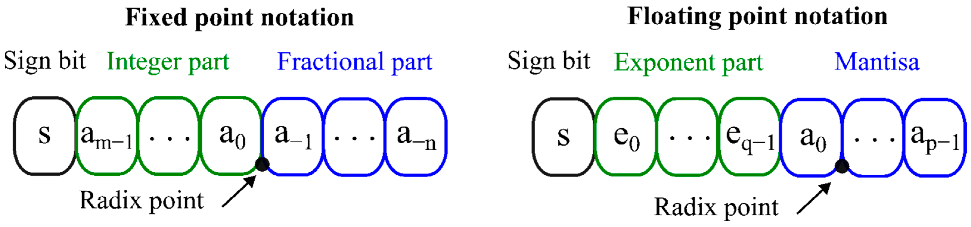
Multiplier architectures are typically classified into fixed-point and floating-point implementations, each offering distinct trade-offs among precision, dynamic range, and hardware cost. Figure 1 provides a comparison between the fixed-point and floating-point formats used in binary number representations. In the fixed-point format, the position of the decimal point is predetermined. This representation includes a sign bit, an integer part, and a fractional part. While floating-point implementations offer enhanced precision and a wider dynamic range than fixed-point designs, these benefits come with trade-offs in hardware complexity, area, performance, and power efficiency.

Figure 1.
Comparison between fixed-point notation and floating-point notation.
The Institute of Electrical and Electronics Engineers (IEEE) 754 standard [21] formally defines floating-point numbers, detailing the representation of single-precision (32-bit) and double-precision (64-bit) formats. This standard states that a floating-point number consists of a sign bit (), an exponent (), and a mantissa (). In the normalized form, the value represented by a floating-point number is expressed as . The range for is [0, 1), and the bit added to is known as the implicit bit. For floating-point numbers of any size, the bias is determined using the formula , where represents the number of bits in . Table 1 provides a summary of the specifics for single- and double-precision formats, which are among the most widely used formats today.

Table 1.
Floating-point formats.
2.2. Floating-Point Multiplier
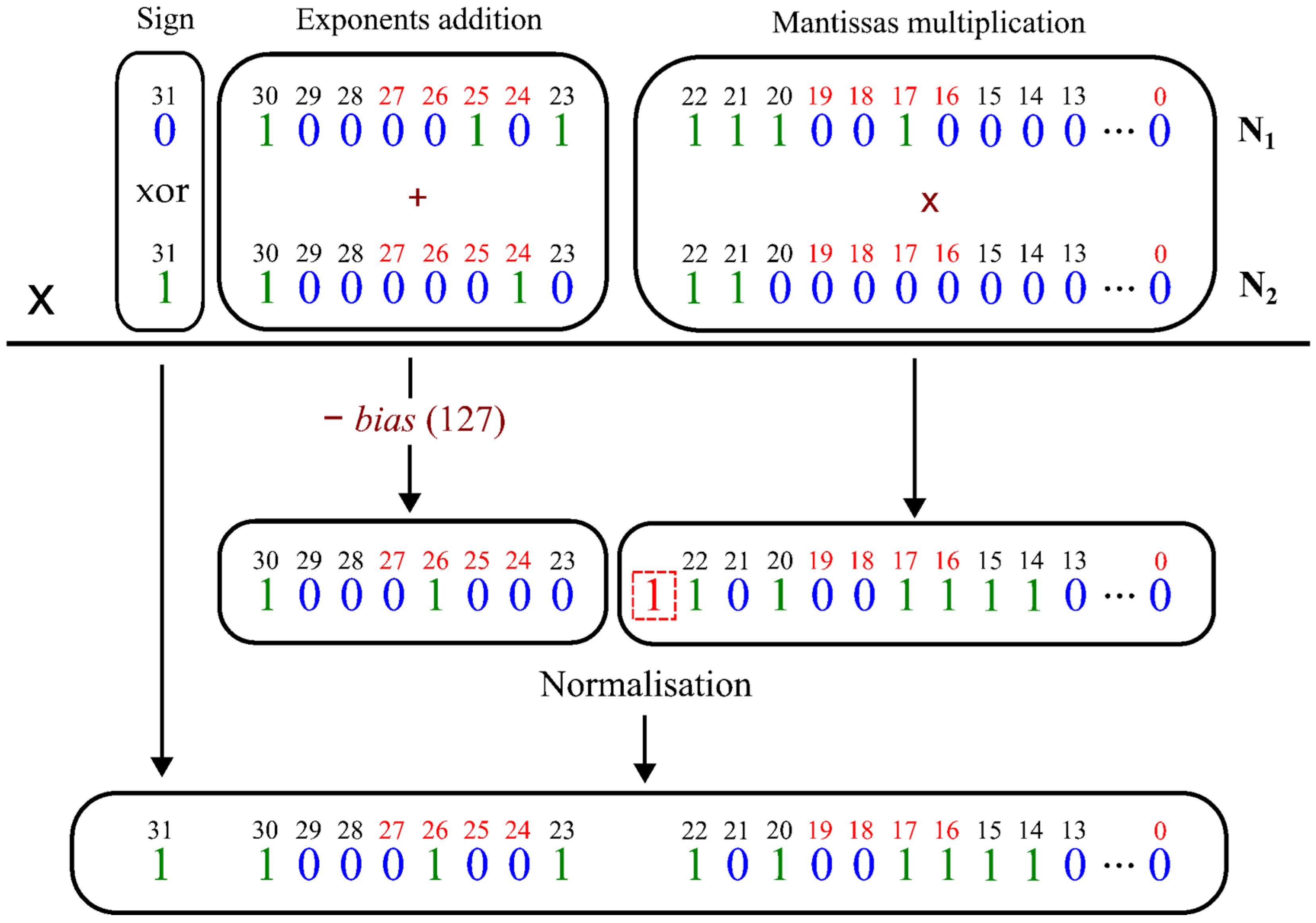
Designers can implement multiplication using a fixed- or floating-point multiplier using the previously described number formats. In general, floating-point arithmetic implementation involves processing the , , and parts separately and then combining them after rounding and normalization. Figure 2 shows the multiplication process for 32-bit floating-point numbers. It involves a fixed-point adder for the exponents, a fixed-point multiplier for the mantissas, and normalization logic for the result. This can be computed using the following steps. First, the sign bits are XORed to obtain the sign bit of the product. Subsequently, the exponents of both operands are added. The bias (127, as shown in Table 1) is subtracted from the sum to allow for both the negative and positive exponent values. Finally, the two mantissas are multiplied and shifted to the range of 1 and 2 to produce a normalized representation. As shown in Figure 2, the exponent is adjusted if a shift happens [22]. The multiplication of mantissas of floating-point numbers can always be viewed as a special case of fixed-point multiplication. Thus, the most critical operations in fixed- and floating-point multiplications can be considered the same.

Figure 2.
Example of single-precision (32-bit) floating-point multiplication according to the IEEE 754 standard.
3. Materials and Methods
Although approximate multipliers have received considerable attention [3,16,23,24], the multipliers designed in this study did not employ an approximation strategy. Numerous binary multiplication techniques have been developed for this purpose. In general, the selection of a specific method typically depends on factors such as the delay, power consumption, area, accuracy, and design complexity. The conventional approach to performing binary multiplication is add/shift, in which the partial products (PPs) are first calculated and then added by adders. The main standard for measuring multiplier algorithms is the number of PPs. Thus, in this study, Wallace and Booth multipliers were designed and compared with the conventional array multiplier. These multiplier architectures represent standard approaches for hardware implementation and are well suited for VLSI in CMOS technology.
3.1. Array Multiplier
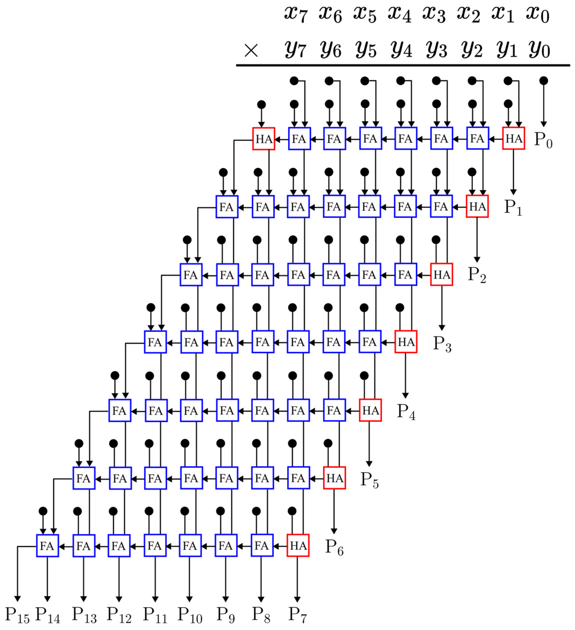
The initial design under consideration is the array multiplier, a straightforward parallel multiplier comprising an array of AND gates, full adders (FAs), and half adders (HAs) [25,26]. Typically, an n-bit array multiplier incorporates an n × n array of AND gates to generate partial products (PPs), n × (n − 2) FAs, and n HAs. Each PP bit is fed into an FA that sums the PP bit (indicated by the black circle in Figure 3) with the sum from the preceding adder and a carry from the less significant preceding adder. The output from each row of ripple-carry adders serves as the input for the subsequent row. Each row of FAs adds a PP to the partial sum, producing a new partial sum and a sequence of carries, as illustrated in Figure 3, for an 8-bit array multiplier.

Figure 3.
An 8-bit array multiplier.
3.2. Wallace Tree Multiplier
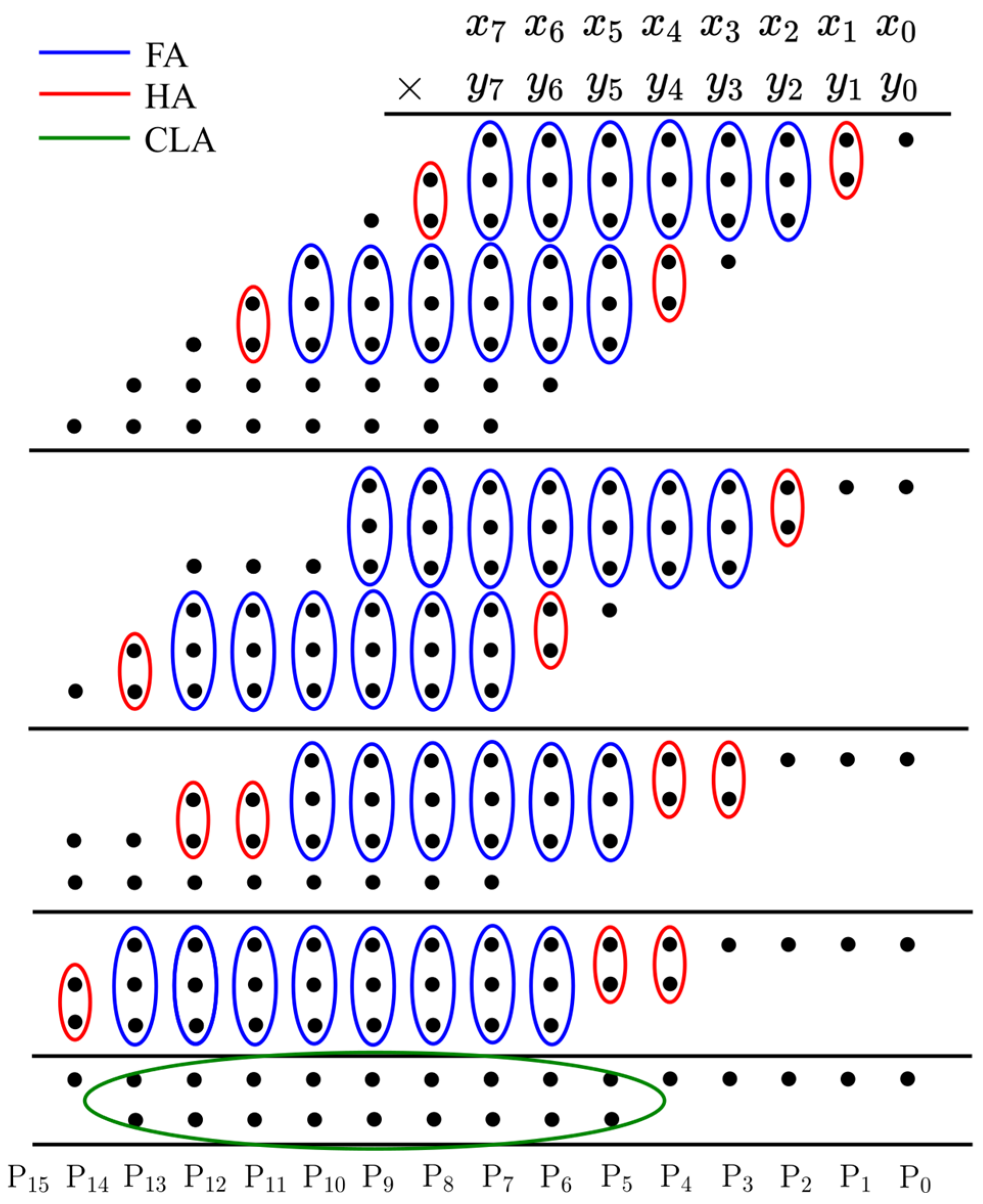
The second design focused on the Wallace tree architecture, which was introduced by Chris Wallace in 1964 to create fast multipliers [27]. This approach uses a network of FAs and HAs to sum the PPs, effectively addressing the carry propagation issue found in array multipliers. In this configuration, the multiplicand is multiplied by the multiplier to produce n2-bit PPs. These are then organized into groups of two or three adjacent rows. The application of FA and HA depends on the number of bits in each group. Single bits are not processed immediately but are carried over to the next stage. The reduction process begins with the rightmost column and continues until only two rows remain. A carry-look-ahead (CLA) adder is then employed to combine these two rows, resulting in the final product. CLA adders offer a speed advantage over the ripple-carry adders used in array multiplier designs. Figure 4 illustrates an 8 × 8 Wallace multiplier, where a single-bit PP is marked by a black circle, and HA, FA, and CLA are represented by red, blue, and green semicircles, respectively.

Figure 4.
An 8-bit Wallace tree multiplier.
3.3. Radix-4 Booth Multiplier
The Booth algorithm, specifically the radix-2 version, was introduced to enhance multiplication efficiency [28]. The radix-4 Booth algorithm, also known as the modified Booth algorithm [29], further optimizes this process by halving the number of PP rows required for multiplication. The third architecture employs the radix-4 Booth algorithm, which is an effective technique for boosting multiplication performance, particularly with two’s complement operands. When implementing the radix-4 Booth algorithm, the multiplier is divided into overlapping groups of three consecutive bits. Each group is encoded and decoded with the multiplicand to produce the corresponding PPs. Generally, the n-bit multiplication using the radix-4 Booth algorithm can be represented as
where and the multiplicand and multiplier are n-bit two’s complement numbers. Based on the continuous three bits of the multiplier , the radix-4 Booth algorithm can generate the corresponding coefficient , which can take on five possible values (±1, ±2, or 0), as illustrated in Table 2. A notable characteristic of this algorithm is that the corresponding PPs are 0 s when the three consecutive bits of the multiplier () are identical.
Table 2.
Radix-4 Booth encoding.
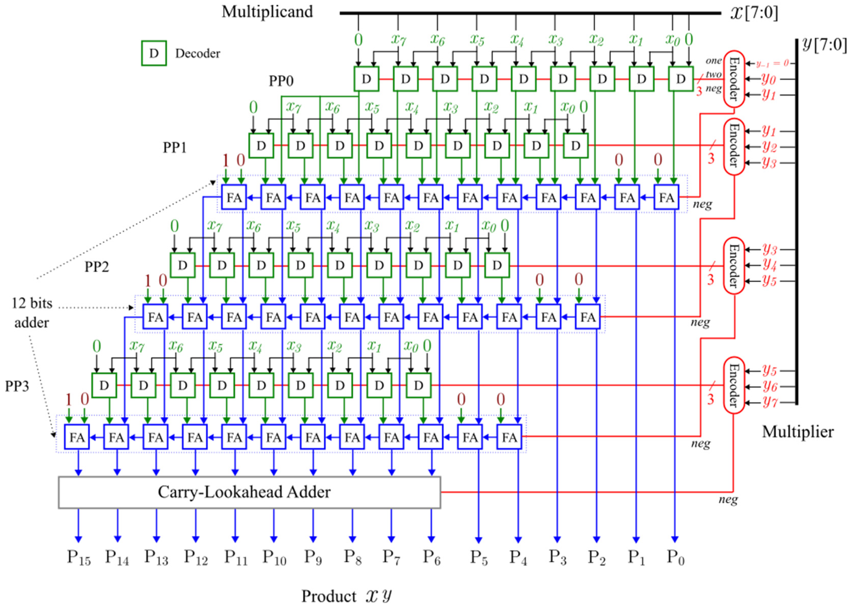
Figure 5 shows the design of an 8-bit radix-4 Booth multiplier. Each row of PP includes one Booth encoder and Booth decoders. Each decoder outputs a single bit of the PP based on the 3-bit signal (one, two, and neg) received from the encoder, as depicted in Figure 5. When the neg signal is zero, the decoder outputs zero if both control signals, one and two, are zero; it outputs when one is activated; and it outputs when two is activated, corresponding to multiplication by 0, 1, and 2, respectively. If the neg signal is one, the unit reverses the output bits mentioned above. Inverting the bits results in a one’s complement, and for a two’s complement, neg must be added to the outcome. Finally, FAs and a CLA combine all PPs to produce the final product.

Figure 5.
An 8-bit radix-4 Booth multiplier.
3.4. VLSI Implementation
Considering the IEEE 754 standard for floating-point numbers [21], 11-, 16-, 24-, 32-, 53-, and 64-bit multipliers were designed. First, the implementation was performed using the VHSIC hardware description language (VHDL), where the acronym VHSIC refers to a very-high-speed integrated circuit [30]. They were then synthesized using Alliance open-source EDA tools [20].
In contrast to commercial design flows, which typically generate layouts tailored to specific technology nodes, Alliance produces symbolic layouts. This abstraction enables design portability across different technological nodes by decoupling the layout from any manufacturing process. In this methodology, the layout is first drawn using an abstract unit known as (lambda). Subsequently, the value of is determined for the target technology to ensure compliance with its specific design rules. However, Alliance tools are currently not suitable for advanced deep submicron technologies, specifically those with feature sizes below 180 nm [20]. This approach offers notable advantages such as the ability to share and publish symbolic layouts without requiring non-disclosure agreements. However, this method has several limitations. One is the inability to utilize the most advanced features of the target process node, which results in less area-efficient layouts.
The synthesis process started with the VHDL analyzer for synthesis (VASY), which converts the RTL design written in VHDL into an understandable language by Alliance. Subsequently, the Boolean minimization (BOOM) tool was executed, which optimized and converted the VASY instructions into simple Boolean equations. The equations were then analyzed with the binding and optimizing on gates (BOOG) tool to obtain the equivalent function using the standard cells provided by the SXLIB library. Additionally, the tool generates a schematic circuit. Subsequently, the circuit was simulated using a simulation tool (ASIMUT) to verify its design. After that, the local optimizations of nets (LOON) tool was used to optimize the critical path by introducing buffers and reducing capacitance. The placer for standards cells (OCP) tool was then used to place the standard cells and establish the physical inputs and outputs. Subsequently, the cell transistors were interconnected with the negotiating router (NERO) tool. Consequently, the circuit layout was obtained. Next, the logical versus extracted (LVX) tool generated a list of nodes to compare the layout with the structural file using COUGAR. Finally, the layout was scaled with the symbolic to real (S2R) tool through a configuration file based on 350 nm CMOS technology.
4. Results and Discussion
This section addresses the verification of the designs to ensure their correct operation as well as the outcomes of the synthesis process. Behavioral and structural simulations were conducted using the ASIMUT to verify the design. As exhaustive testing of all multipliers is impractical, they were tested using random inputs applied through a pattern file. The scripts were written to synthesize the array, Wallace, and radix-4 Booth multipliers. To ensure a fair comparison, all the designs were given identical synthesis parameters. These parameters were utilized in the LOON, BOOM, and BOOG tools to obtain the smallest delay constraint for every multiplier. Detailed synthesis reports were generated for the area and delay. The timing report shows the complete critical path, with the delay associated with the path.
4.1. Synthesis Results
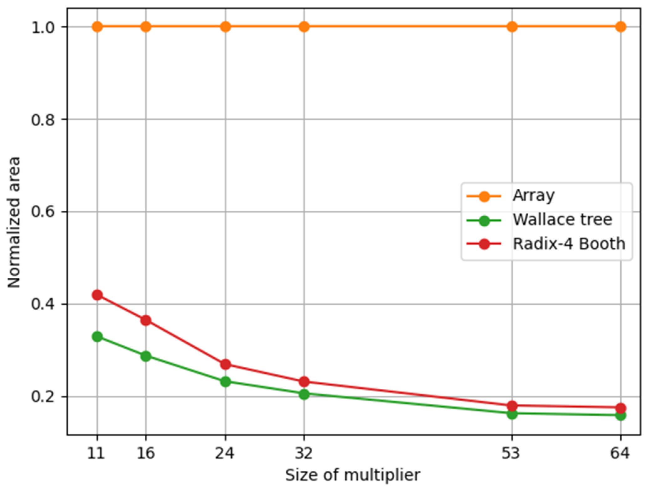
Table 3 presents a comparative analysis of the synthesis results regarding the transistor count, area, and delay for various designed multipliers. The array multiplier showed the highest transistor count. Using Alliance tools, a 64-bit array multiplier was successfully synthesized, surpassing the 875,000 transistors employed in the industrial-scale project of a static control superscalar microprocessor, which was synthesized using the same tools [20]. Both Wallace and radix-4 Booth multipliers effectively reduce the number of transistors. Figure 6 depicts the area of each multiplier, which was normalized relative to the array multiplier. As expected, the findings in Figure 6 and Table 3 reveal a significant increase in area with increasing size of the array multiplier [26]. The Wallace multiplier consistently exhibited the smallest area across all multiplier lengths, with this reduction being more pronounced for shorter lengths. As the multiplier size increases, the area of the Wallace multiplier converges to that of the radix-4 Booth multiplier.
Table 3.
Synthesis results from Alliance in 350 nm technology.

Figure 6.
Area of different multipliers for Alliance 350 nm CMOS technology.
Alliance tools employ various cells to optimize the delay in each design. The synthesis was performed using standard cells from the SXLIB library. Consequently, different cells were selected to optimize the delay in each design due to their distinct architectures and final adder sizes. The substantial area observed in the designs can thus be attributed to the use of larger standard cells to meet the minimum delay constraint as well as the limitation in utilizing the most advanced features owing to the symbolic layout employed.
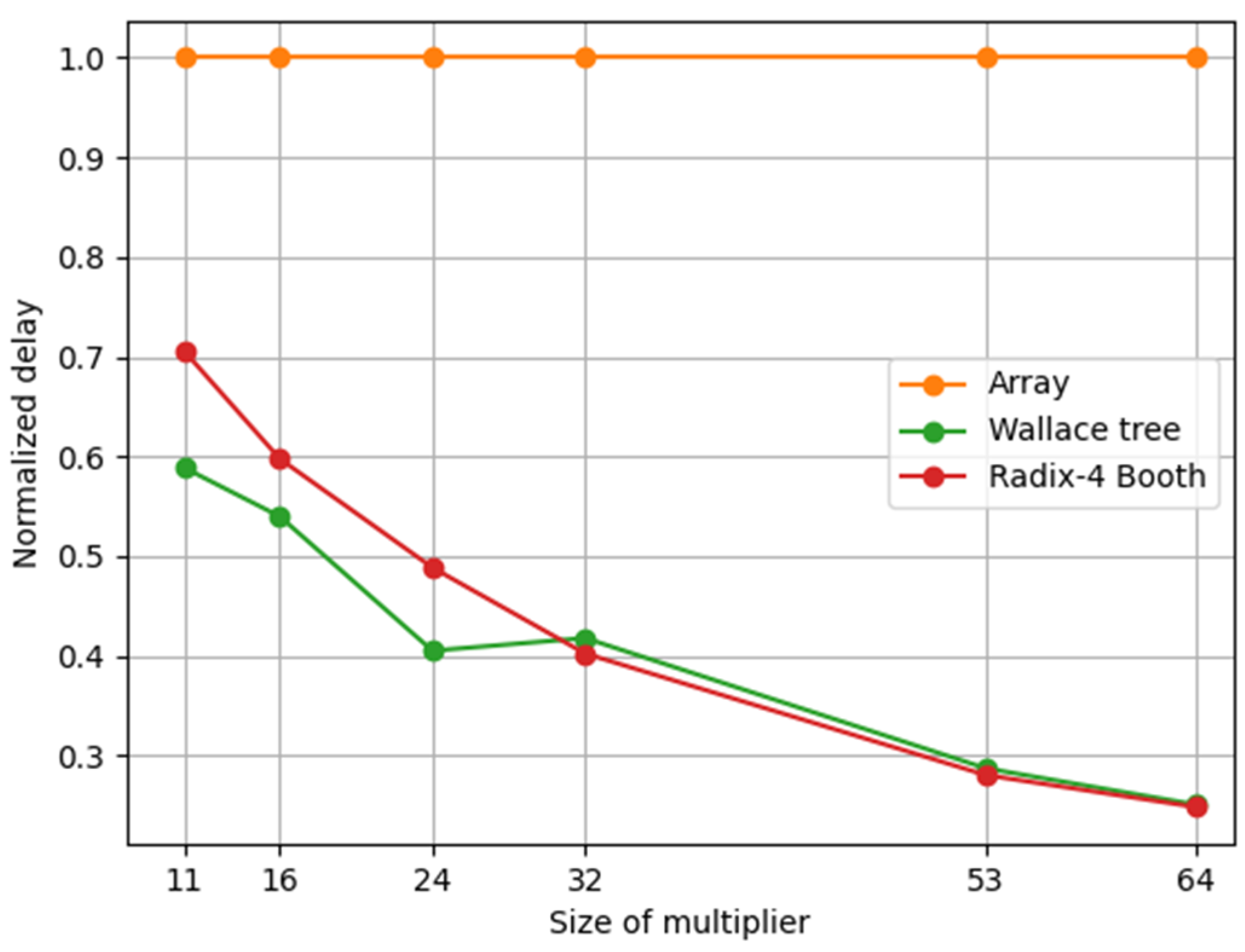
Figure 7 shows the normalized delay for each multiplier. The delay measurement is performed along the critical path, where the slowest signal must propagate. Wallace provided the lowest latency for the 11-, 16-, and 24-bit multipliers, consistent with the findings of the 8-bit and 16-bit multiplier designs in [17,31], respectively. For the 32-, 53- and 64- bit multipliers, Wallace experienced a delay nearly identical to that of the radix-4 Booth multiplier, aligning with the findings of the 32-bit multiplier design using 350 CMOS technology [15]. Wallace offers fast speed because instead of linear dependency, as in the array multiplier, the total delay is proportional to the logarithm of the multiplier operand’s word length [32]. In Table 3, the logarithmic behavior of the delay for the Wallace multiplier can be corroborated by increasing the word length, whereas the array multiplier exhibited linear delay increments.

Figure 7.
Delay of different multipliers based on Alliance 350 nm CMOS technology.
The size of the final CLA adder and logic levels required for the Wallace tree and radix-4 Booth multipliers are listed in Table 4. The Wallace tree multiplier had the smallest final adder. Radix-4 Booth and Wallace require almost the same number of logic levels to implement the final adder, which explains why they have almost the same delay in the 32-, 53-, and 64-bit multipliers (see Figure 7).
Table 4.
Synthesis results from Alliance based on 350 nm CMOS technology.
The results shown in Figure 6 and Figure 7 and Table 3 indicate that the most important advantage of an array multiplier is its high degree of uniformity. Thus, to perform small multiplications, an array multiplier is preferable owing to its simplicity and structural regularity. However, it was shown that the delay and area become very large for large word lengths in an array multiplier [25,26,33]. Therefore, for large multiplications, such as the multiplication of floating-point numbers, a high-speed multiplier such as Wallace or radix-4 Booth may be used. However, the array multiplier can be efficiently optimized, as shown in [10,33], for large multiplications, as required in floating-point multipliers.
Owing to the hierarchically designed structure shown in Figure 4, the Wallace tree multiplier is faster than the array multiplier because of the parallel reduction in bits in the PP layers by HAs and FAs. However, physical design implementation becomes more complex as the word length of the multiplier increases. This can be attributed to the interconnection wires and logic levels used, as listed in Table 4. In addition, by analyzing its architecture, the number of FAs and HAs used in the initial stage of PP tree reduction did not reduce the number of PPs. Several authors have attempted to improve the performance of Wallace multipliers [32,34].
Because the radix-4 Booth algorithm can reduce the number of PPs by half, as shown in Figure 5, it is another type of fast multiplier with low area consumption. Moreover, the Booth multiplier can be implemented in 26 distinct configurations, including radix-2, radix-4, and radix-8, among others. However, these higher radix configurations necessitate additional logic to implement Booth encoding. Radix-4 Booth is widely used to improve the performance of multipliers [7,8]. However, this is the most complex architecture for implementation in VLSI design.
Alliance EDA tools lack tools for estimating the power consumption of VLSI designs. The overall power consumption of an integrated circuit can be defined as
where the first and second terms represent the dynamic and static power consumption, respectively. is the switching activity parameter, is the total capacitance load, is the supply voltage, is the operating frequency, and is the leakage current. According to (2), dynamic power consumption can be reduced by minimizing the switching activity.
As shown in Table 3, the array multiplier is anticipated to have significant power consumption due to its large number of transistors and extended critical path. By contrast, the Wallace multiplier is expected to consume less power than the array multiplier. Most of the power dissipation in the Wallace tree multiplier occurs during PP tree reduction. However, the number of transistors and transitions is reduced because of the accelerated PP reduction in smaller multipliers [17,18]. As the word length increases, power consumption may increase significantly because of the increased glitching from complex wiring routing [12]. The radix-4 Booth algorithm involves operations for the coefficient of Equation (1) with values of ±1 and ±2, which are generated by the encoders, as shown in Figure 5. This complexity is expected to result in the highest power consumption [7,17].
4.2. Floating-Point Multipliers
The crucial part and main bottleneck in the performance of floating-point multipliers is mantissa multiplication. All other related floating-point operations for exponent, normalization, rounding, and exceptional case handling (see Figure 2) are relatively simple, and it is much easier to partition their data path, which generally contains some comparators, small adders/subtractors, and multiplexers.
According to the IEEE 754 standard, the mantissa of half-, single-, and double-precision floating-point numbers has 11-, 24-, and 53-bit lengths, respectively. The lowest delay was achieved using the Wallace tree and radix-4 Booth multipliers. However, related studies on floating-point multipliers based on the Booth algorithm [35,36] show that many changes require an algorithm for unsigned mantissa multiplication. As shown in Figure 5, the radix-4 Booth multiplier is used for fixed-point signed multiplication. Thus, the considerations of multiplier recoding, based on two’s complement form, and sign extension are not needed in floating-point multipliers, because the mantissa is an unsigned number.
By taking the lowest delay found as a reference, which corresponds to the 11-bit Wallace multiplier, it can be inferred from Table 3 that the delay of the 24- and 53-bit Wallace multipliers increased by 137% and 190%, respectively. Compared with the radix-4 Booth multiplier, the delay of the 24- and 53-bit multipliers is increased by 165% and 185%, respectively. This analysis shows that the Wallace tree multiplier has the lowest delay in mantissa multiplication of single-precision floating-point numbers. Meanwhile, there was no significant difference between the Wallace and radix-4 Booth multipliers for mantissa multiplication of double-precision floating-point numbers. As shown in Figure 6 and Table 3, the Wallace tree multiplier uses a smaller area than the radix-4 Booth multiplier for both the single- and double-precision floating-point multipliers.
5. Conclusions
In the present study, a delay/area performance comparison of the array, Wallace tree, and radix-4 Booth multipliers was presented. Several multipliers were successfully designed using Alliance tools. The synthesized output data were analyzed using 11-, 16-, 24-, 32-, 53-, and 64-bit multipliers. These findings indicate that the area and delay significantly increase with the size of the array multiplier. In particular, the Wallace multiplier increases smoothly in a quadratic manner, whereas stepwise linear growth occurs with radix-4 in delay performance. In addition, the Wallace multiplier exhibited the lowest latency for the 11-, 16-, and 24-bit multipliers. However, for the 32-, 53-, and 64-bit multipliers, Wallace had almost the same delay as the radix-4 Booth multiplier.
Using the 11-bit Wallace multiplier with the lowest delay as a reference, the delays of the 24-bit and 53-bit Wallace multipliers increased by 137% and 190%, respectively. Compared with the radix-4 Booth multiplier, the delay of the 24- and 53-bit multipliers is increased by 165% and 185%, respectively. Thus, depending on the application, either the Wallace tree or the radix-4 Booth multiplier can be used in single- and double-precision floating-point multiplications.
Designers of digital circuits may use this study to choose an optimal architecture of fixed- or floating-point multipliers for VLSI implementation, considering their design constraints. For future possibilities, the scope of this paper suggests that we could perform a comparison between Alliance and commercial EDA tools.
Author Contributions
Conceptualization and writing—original draft preparation, A.J.; formal analysis and writing—review and editing, A.M.; data curation and validation A.J. All authors have read and agreed to the published version of the manuscript.
Funding
This work was published with financial support from the Instituto de Innovación y Competitividad de la Secretaría de Innovación y Desarrollo Económico del Estado de Chihuahua (2022–2028) and the Universidad de Guadalajara through the 2025 PROSNII program. The authors express their gratitude for the partial economic assistance provided to cover article processing charges.
Institutional Review Board Statement
Not applicable.
Informed Consent Statement
Not applicable.
Data Availability Statement
Data supporting this study are openly available on Google Drive at https://drive.google.com/drive/folders/1A4UQ8ffPzqW797LHuTk1LrbxBk6rottg?usp=sharing, accessed on 20 February 2025.
Acknowledgments
The authors express their gratitude to Universidad Autónoma de Ciudad Juárez for granting access to the laboratory facilities at the Centro de Investigación en Ciencia y Tecnología Aplicada (https://www.uacj.mx/IIT/CICTA/, accessed on 10 February 2025) and to Universidad de Guadalajara for its facility support. They also extend their thanks to the Secretaría de Ciencia, Humanidades, Tecnología e Innovación (SECIHTI) for providing the research fellowship.
Conflicts of Interest
The authors declare no conflict of interest.
Abbreviations
The following abbreviations are used in this manuscript:
| VLSI | very-large-scale integration |
| CMOS | complementary metal–oxide–semiconductor |
| VHDL | VHSIC hardware description language |
| FAs | accurate full adders |
| GDI | gate diffusion input |
| EDA | electronic design automation |
| RTL | register-transfer level |
| IEEE | Institute of Electrical and Electronics Engineers |
| PPs | partial products |
| FAs | full adders |
| HAs | half adders |
| CLA | carry-look-ahead |
References
- Ibrahim, A.; Gebali, F. Enhancing Field Multiplication in IoT Nodes with Limited Resources: A Low-Complexity Systolic Array Solution. Appl. Sci. 2024, 14, 4085. [Google Scholar] [CrossRef]
- Jiménez, A.; Sauceda, Á.; Muñoz, A.; Duarte, J.; Mireles, J., Jr. FPGA-Based Hardware Implementation of Homodyne Demodulation for Optical Fiber Sensors. Photonics 2023, 10, 258. [Google Scholar] [CrossRef]
- Tavakkoli, E.; Shokri, S.; Aminian, M. Comparison and design of energy-efficient approximate multiplier schemes for image processing by CNTFET. Int. J. Electron. 2023, 111, 813–834. [Google Scholar] [CrossRef]
- Moss, J.M.D.; Boland, D.; Leong, H.W.P. A two-speed, radix-4, serial–parallel multiplier. IEEE Trans. Very Large Scale Integr. (VLSI) Syst. 2019, 27, 769–777. [Google Scholar] [CrossRef]
- Shanmuganathan, R.; Brindhadevi, K. Comparative analysis of various types of multipliers for effective low power. Microelectron. Eng. 2019, 214, 28–37. [Google Scholar] [CrossRef]
- Cariow, A.; Naumowicz, M.; Handkiewicz, A. Structure and Principles of Operation of a Quaternion VLSI Multiplier. Appl. Sci. 2024, 14, 8123. [Google Scholar] [CrossRef]
- Tang, X.; Li, Y.; Lin, C.; Shang, D. A Low-Power Area-Efficient Precision Scalable Multiplier with an Input Vector Systolic Structure. Electronics 2022, 11, 2685. [Google Scholar] [CrossRef]
- Fu, C.; Zhu, X.; Huang, K.; Gu, Z. An 8-bit Radix-4 Non-Volatile Parallel Multiplier. Electronics 2021, 10, 2358. [Google Scholar] [CrossRef]
- Leon, V.; Xydis, S.; Soudris, D.; Pekmestzi, K. Energy-efficient VLSI implementation of multipliers with double LSB operands. IET Circ. Device Syst. 2019, 13, 816–821. [Google Scholar] [CrossRef]
- Lin, J.-F.; Chan, C.-Y.; Yu, S.-W. Novel Low Voltage and Low Power Array Multiplier Design for IoT Applications. Electronics 2019, 8, 1429. [Google Scholar] [CrossRef]
- Mandloi, A.; Pawar, S. VLSI design of APT-VDF using novel variable block sized ternary adder and multiplier. Microprocess. Microsyst. 2020, 78, 103266. [Google Scholar] [CrossRef]
- Sharma, B.; Mishra, R.; Didwania, N.; Mitra, A.; Baksi, A. Comparison of Single Precision Floating Point Multiplier Using Different Multiplier Algorithms. IJEEDC 2015, 3, 106–109. [Google Scholar]
- Spagnolo, F.; Corsonello, P.; Frustaci, F.; Perri, S. Efficient implementation of signed multipliers on FPGAs. Comput. Electr. Engin. 2024, 116, 109217. [Google Scholar] [CrossRef]
- Lee, C.Y.H.; Hiung, L.H.; Lee, S.W.F.; Hamid, N.H. A performance comparison study on multiplier designs. In Proceedings of the 2010 International Conference on Intelligent and Advanced Systems, Kuala Lumpur, Malasya, 15–17 June 2010; pp. 1–6. [Google Scholar]
- Swee, K.L.S.; Hiung, L.H. Performance comparison review of 32-bit multiplier designs. In Proceedings of the 2012 4th International Conference on Intelligent and Advanced Systems (ICIAS2012), Kuala Lumpur, Malaysia, 12–14 June 2012; pp. 836–841. [Google Scholar]
- Masadeh, M.; Hasan, O.; Tahar, S. Comparative Study of Approximate Multipliers. In Proceedings of the 2018 on Great Lakes Symposium on VLSI, Chicago, IL, USA, 23–25 May 2018; pp. 415–418. [Google Scholar]
- Praveen Kumar, Y.G.; Kariyappa, B.S.; Shashank, S.; Bharath, C.N. Performance Analysis of Multipliers Using Modified Gate Diffused Input Technology. IETE J. Res. 2020, 68, 3887–3899. [Google Scholar] [CrossRef]
- Bansal, M.; Barthi, V.; Chander, V. Comparison between Conventional Fast Multipliers and Improved Fast Multipliers using PTL Logic. In Proceedings of the 3rd International Conference on trends in Material Science and Inventive Material (ICTMIM 2021), Coimbatore, India, 12–13 March 2021. [Google Scholar]
- Padmanabhan, K.K.; Seerengasamy, U.; Ponraj, A.S. High-Speed Grouping and Decomposition Multiplier for Binary Multiplication. Electronics 2022, 11, 4202. [Google Scholar] [CrossRef]
- Alliance/Coriolis VLSI CAD Tools. Available online: http://coriolis.lip6.fr/ (accessed on 10 April 2025).
- IEEE Std 754-2019; Revision of IEEE 754-2008: IEEE Standard for Floating-Point Arithmetic. IEEE: New York, NY, USA, 2019; pp. 1–84.
- Jaiswal, M.K.; Cheung, R.C.C. VLSI Implementation of Double-Precision Floating-Point Multiplier Using Karatsuba Technique. Circ. Syst. Signal Pr. 2013, 32, 15–27. [Google Scholar] [CrossRef]
- Ullah, S.; Rehman, S.; Shafique, M.; Kumar, A. High-Performance Accurate and Approximate Multipliers for FPGA-based Hardware Accelerators. IEEE Trans. Comput.-Aided Des. 2022, 41, 211–224. [Google Scholar] [CrossRef]
- Waris, H.; Wang, C.; Liu, W.; Lombardi, F. AxBMs: Approximate Radix-8 Booth Multipliers for High-Performance FPGA-Based Accelerators. IEEE Trans. Circuits Syst. II Express Briefs 2021, 68, 1566–1570. [Google Scholar] [CrossRef]
- Balasubramanian, P.; Mastorakis, N.E. Speed, Power and Area Optimized Monotonic Asynchronous Array Multipliers. J. Low Power Electron. Appl. 2024, 14, 1. [Google Scholar] [CrossRef]
- Mathew, K.; Latha, S.A.; Ravi, T.; Logashanmugam, E. Design and analysis of an array multiplier using an area efficient full adder cell in 32nm CMOS technology. Int. J. Eng. Sci. 2013, 2, 8–16. [Google Scholar]
- Wallace, C.S. A suggestion for a fast multiplier. IEEE Trans. Electron. Comput. 1964, 13, 14–17. [Google Scholar] [CrossRef]
- Booth, A.D. A Signed binary multiplication technique. Q. J. Mech. Appl. Math. 1951, 4, 236–240. [Google Scholar] [CrossRef]
- Chu, T.-A. Booth multiplier with low power, high performance input circuitry. US Patent 6,393,454, 21 May 2002. [Google Scholar]
- IEEE Std 1076-2008; IEEE Standard VHDL Language Reference Manual. IEEE: Piscataway, NJ, USA, 2019; pp. 1–673.
- Biswarup, M. A comprehensive review of low power fixed with digital multiplier architectures. J. Mech. Contin. Math. Sci. 2024, 19, 59–76. [Google Scholar] [CrossRef]
- Solanki, V.; Darji, A.D.; Singapuri, H. Design of Low-Power Wallace Tree Multiplier Architecture Using Modular Approach. Circ. Syst. Signal Pr. 2021, 40, 4407–4427. [Google Scholar] [CrossRef]
- Balasubramanian, P.; Nayar, R.; Maskell, D.L. Approximate Array Multipliers. Electronics 2021, 10, 630. [Google Scholar] [CrossRef]
- Waters, R.S.; Swartzlander, E.E. A reduced complexity wallace multiplier reduction. IEEE Trans. Comput. 2010, 59, 1134–1137. [Google Scholar] [CrossRef]
- Jiang, X.; Xiao, P.; Qiu, M.; Wang, G. Performance effects of pipeline architecture on an FPGA-based binary32 floating point multiplier. Microprocess. Microsyst. 2013, 37, 1183–1191. [Google Scholar] [CrossRef]
- Mustafa, G. A novel IEEE rounding algorithm for high-speed floating-point multipliers. Integration 2007, 40, 549–560. [Google Scholar] [CrossRef]
Disclaimer/Publisher’s Note: The statements, opinions and data contained in all publications are solely those of the individual author(s) and contributor(s) and not of MDPI and/or the editor(s). MDPI and/or the editor(s) disclaim responsibility for any injury to people or property resulting from any ideas, methods, instructions or products referred to in the content. |
© 2025 by the authors. Licensee MDPI, Basel, Switzerland. This article is an open access article distributed under the terms and conditions of the Creative Commons Attribution (CC BY) license (https://creativecommons.org/licenses/by/4.0/).