Article

Innovative Grouting Reinforcement Techniques for Shield Tunnels: A Case Study on Surface Settlement Mitigation

1
Hubei Key Laboratory of Environmental Geotechnology and Ecological Remediation for Lake & River, Hubei University of Technology, Wuhan 430068, China
2
Key Laboratory of Intelligent Health Perception and Ecological Restoration of Rivers and Lakes, Ministry of Education, Hubei University of Technology, Wuhan 430068, China
3
Hubei Provincial Ecological Road Engineering Technology Research Center, Hubei University of Technology, Wuhan 430068, China
*
Author to whom correspondence should be addressed.
Appl. Sci. 2025, 15(9), 4623; https://doi.org/10.3390/app15094623
Submission received: 7 March 2025 / Revised: 17 April 2025 / Accepted: 20 April 2025 / Published: 22 April 2025

Abstract

:
This study investigates the impact of flower tube grouting reinforcement on surface settlement in shield tunnels under complex geological conditions, using the Wuhan Metro Line 12 project as a case example. A simulation model was constructed using PLAXIS 3D software to analyze surface settlement under unreinforced conditions and compare it with reinforced conditions. The effects of grouting pressure, soil pressure, and tunnel depth on surface settlement were also examined. Results indicate that surface settlement decreases with increasing tunnel depth, decreasing by approximately 0.15 mm per 1 m increase in depth. Soil silo pressure positively correlates with surface settlement, increasing by about 0.08 mm for every 10 kPa rise in pressure. A critical grouting pressure of approximately 400 kPa was identified, beyond which surface settlement increases with higher grouting pressure. Flower tube grouting significantly reduced surface settlement, by 92% on average, limiting maximum settlement to 3 mm. Numerical simulation results closely matched field monitoring data, with errors within ±0.5 mm, validating the model’s reliability. The study demonstrates that flower tube grouting reinforcement effectively mitigates the effects of tunnel depth, grouting pressure, and soil bin pressure on surface settlement, ensuring project safety when shield tunnels pass through sensitive areas such as long-distance railroads.

1. Introduction

As urbanization accelerates and the density of surface buildings and transportation facilities continues to rise, surface transportation is no longer able to meet the growing demand for travel, and underground tunnels are therefore being constructed more and more frequently. However, the tunneling process is often accompanied by ground settlement, which can adversely affect surface buildings and the existing railroad system. For this reason, ensuring the safety of tunnel construction and effectively controlling the ground settlement are key tasks [1,2]. To this end, effective reinforcement means must be used to minimize the impact of tunnel excavation on the amount of ground settlement [3,4].
More and more scholars have begun to focus on what can be performed to better reduce the impact of surface subsidence to control the impact of surface subsidence. Many scholars have revealed the settlement mechanism of shield tunnels in conjunction with urban shield tunnels: the construction of double-lane tunnels causes huge settlement on the surface above the centerline of the tunnel, and scholars have reduced changes in surface settlement by reinforcing the soil body, and some of these strategies are methods with which to optimize grouting pressure, soil bin pressure, and so on. However, there are still many great challenges, such as the improvement of prediction models for specific structural settlement criteria and for complex crossing geometries in soft soils. Some scholars have analyzed the theory of changes in surface settlement caused during shield tunnel excavation and found that surface settlement during shield tunnel excavation is symmetrically distributed and conforms to Peck’s theoretical formula [5,6,7,8]. Recent research by some scholars has revealed the critical impact of shield tunneling and some reinforcement methods, such as the reinforcement of bridges, as well as the control of groundwater in the subsoil layer to reduce the impact of surface settlement [9,10,11,12]. Some scholars have explored the key shield boring mechanism, where double tunneling induces asymmetric settlement, as well as the destruction of asymmetric center columns. Some scholars have reduced surface settlement in soft soils by 50% through a two-fluid system, while controlling grouting parameters to minimize soil disturbance. This was verified with numerical simulation, which was consistent with the field data and confirmed the effectiveness of structural reinforcement [13,14,15,16]. Other reinforcement strategies have also been used, such as the use of UHPG for reinforcement in the case of diagonal tunneling, and the use of rubble–cement composites for soil reinforcement, both of which have been effective in reducing changes in surface settlement [17,18,19,20]. Some scholars also adjust the digging attitude, as well as change the shape of the shield machine to reduce the impact of the shield tunnel excavation process brought about by changes in surface settlement; these methods are also certainly effective, but there are some shortcomings that need to be remedied, such as the integrity of the predictive model of complex terrain and other issues [21,22,23,24,25]. Some scholars have also studied the new SCJB construction method (shaft-roofed box combination) for underground stations to control surface settlement within 15 mm; a reinforcement study has been carried out on the settlement of small-radius curved tunnels [26,27].
However, with urban planning, space constraints mean that many railways must cross existing railways. The impact caused by trains cannot be equated with static loads. To take into account the real situation of the actual project, the abovementioned reinforcement is not very suitable for construction under such working conditions, and a new reinforcement method must be found to reinforce the subsoil layer to avoid impacting, as much as possible, the operational safety of the existing railway. In response to this phenomenon, some scholars have also conducted similar studies, such as through the grouting reinforcement of the water platform, so as to achieve a shield tunnel to protect the surface water quality and other measures; grouting reinforcement may be a more secure choice for railway groups [28,29]. Some scholars have conducted numerical simulations through PLAXIS 3D software (v2024.1.0.1060) to explore the main factors affecting the change in surface settlement, and some scholars have adopted measures such as adding a wall in the middle of the twin tunnels to reduce the amount of surface settlement. It shows that PLAXIS 3D has strong applicability in simulating shield excavation [30,31,32].
Although the current research in the field of shield tunnelling has made some progress in many aspects, there are still some key problems that need to be solved. On the one hand, a comprehensive and in-depth understanding of the coupling relationship between complex geological conditions and construction parameters during shield tunnel construction has not yet been developed, which makes it difficult to accurately predict and control the construction effects in actual projects, such as surface settlement, ground disturbance, and other problems that still occur from time to time. On the other hand, when considering the combined effects of multiple factors, existing studies are often not systematic and comprehensive, and they fail to fully cover the dynamic changes in the construction process and the effects of different environmental conditions. This study aims to explore these issues in depth and, through the comprehensive use of numerical simulation and field experimentation, to reveal the intrinsic connection between the factors in the shield construction process, establish a more accurate and effective prediction and control model, and provide theoretical support and technical guidance for the safe and efficient construction of shield tunnelling projects.
Previous studies have been adequate, but there are fewer soil reinforcement methods for shield tunnels underneath long-distance railway complexes. This study focuses on the section between the Tea Research Institute Station and Qingling Station of Wuhan Metro Line 12 as the research object. A PLAXIS 3D model incorporating the hardening and softening behavior of soil was established to systematically compare the spatial distribution differences in ground settlement before and after grouting reinforcement for the geological characteristics of the shield tunnel penetrating a long distance through a water-rich sand layer. Through orthogonal experimental design, the sensitivity thresholds of tunnel depth, soil chamber pressure, and grouting pressure under both reinforced and unreinforced conditions have been identified, leading to the proposal of an optimization criterion for grouting parameters based on the critical pressure ratio. We hypothesize that by considering the coupling of geological conditions, shield parameters, and the construction environment during shield tunnel construction, we can establish an optimal reinforcement method that can effectively control the surface settlement and deformation of the surrounding soil caused by shield tunnel construction. The impact of grouting reinforcement on surface settlement magnitude is highlighted by comparing reinforced and unreinforced states. The full technical route is shown in Figure 1.

2. Projects and Materials

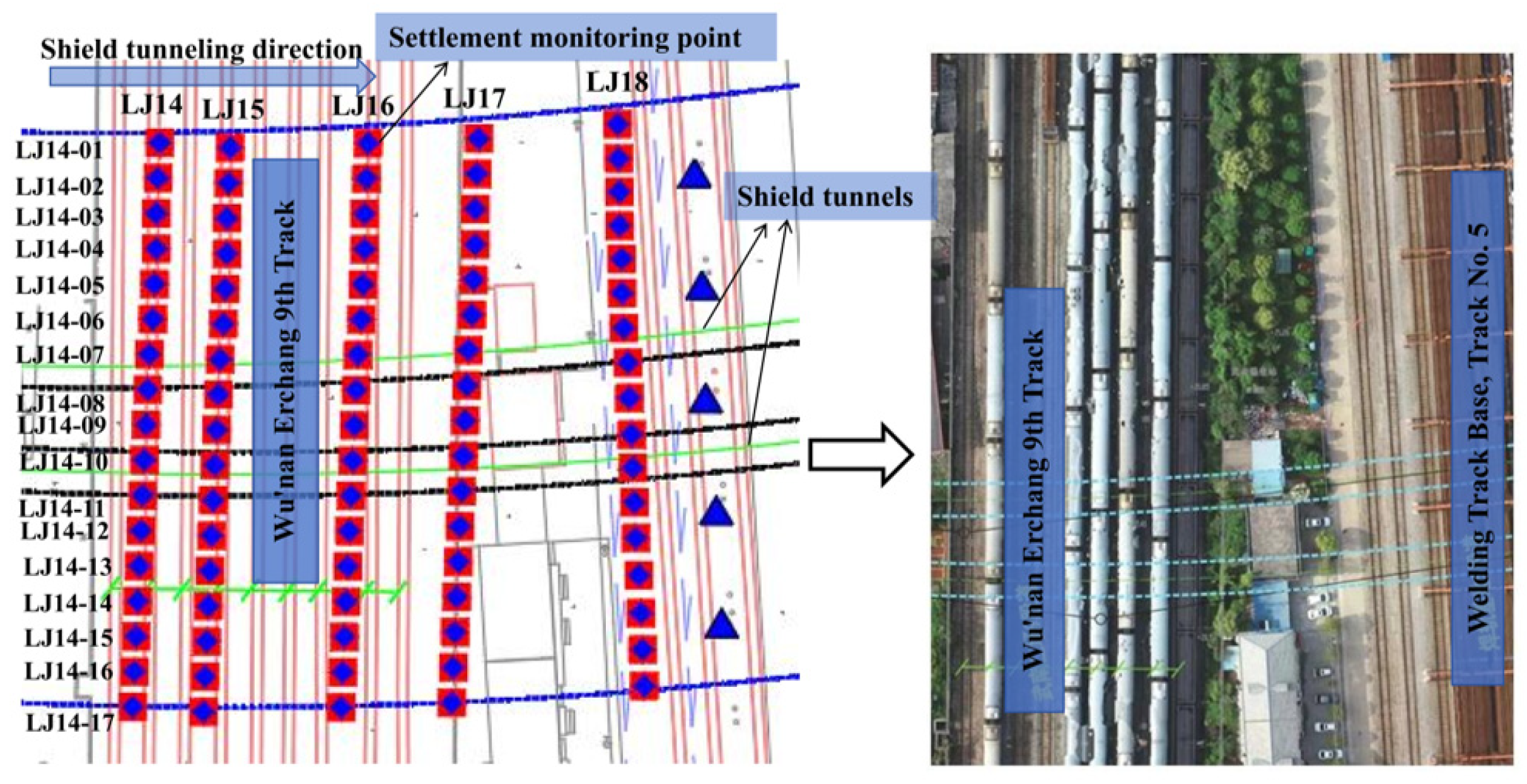
2.1. Project Overview

The section from the Tea Research Station to Qingling Station extends westward underground from the Tea Research Station, successively passing through the Banqiao Village parking lot, Wuhan Metro Line 7, Hubei University of Technology dormitory, the river patrol area, the Hubei University of Technology, and the Wunan formation station. An air shaft is located at DK35 + 150 on the right side, after which the line enters Bisha 3 Road, with Qingling Station situated on the western side of the intersection of Bisha 3 Road and Fengsheng Road. The longitudinal profile of this section is V-shaped, with a maximum gradient of 27‰ and a minimum gradient of 5‰. The tunnel overburden depth varies significantly within this interval, ranging from a minimum of 15.8 m to a maximum of 31.9 m.

2.2. Soil Material

In order to study the effect of shield tunnel excavation on surface settlement, the CK34 + 800.00~CK34 + 883.00 section of the left line is selected as the numerical simulation section in this study. The total length of this section is 84.5 m, and it passes under the railroad group with complicated geological conditions. According to the geological investigation data, the soil layers under the simulation section are (1-2) plain fill; (3-1), (3-4), (7-2), and (7-3) silty clay; (8-1) silty sand; (8-1a) silty clay; (15a-1) strongly weathered muddy siltstone; and (15a-2) moderately weathered muddy siltstone, in that order. The simulated tunnel depth is 27.35 m, mainly through the (15a-1) strongly weathered muddy siltstone soil layer. These geological and soil layer data are all derived from the geological survey report in the project data, which provides information on the stratification of soil layers as well as the physical and mechanical property indexes of each layer, such as water content, density, porosity, cohesion, angle of internal friction, etc. The physical and mechanical parameters of each soil layer are shown in Table 1.
In this study, the consistency of the two is compared and analyzed by the numerical simulation method, combined with field monitoring data, in order to verify the reliability of the numerical simulation method. The angle between the tunnel axis and the horizontal plane in the simulation section is 176°, and the tunnel excavation direction as well as the stratum distribution characteristics are shown in Figure 2. The numerical simulation is based on finite element analysis software, and a three-dimensional numerical model is established by considering the nonlinear mechanical behavior of the soil body and the influence of the shield construction parameters (such as grouting pressure, soil chamber pressure, etc.). The boundary conditions of the model are set according to the actual engineering geological conditions, and the stress–strain relationship of the soil body in addition to the disturbance effect of the shield tunneling on the surrounding soil body are considered in the simulation process.

2.3. Soil Reinforcement Measures

The subsoil structure in the study area is complex, mainly including plain fill, clay, silty powdery clay, powdery clay, powdery fine sand, muddy siltstone, and other soil layers. It is difficult for the natural mechanical properties of these soil layers to meet the requirements of railroad operation in terms of foundation stability and safety. If effective soil reinforcement measures are not taken, significant surface settlement may be triggered during shield tunnel excavation, which may have a serious impact on the normal operation of the railroad group above. Therefore, in order to ensure the safety of railroad operation and control the surface settlement, it is necessary to reinforce the soil above and around the tunnel.
In view of the above problems, the project team adopted the flower tube grouting reinforcement method to treat the soil body. The reinforcement scope is mainly concentrated in the 30 m range above and on both sides of the centerline of the tunnel, and the grouting holes are arranged along the railroad section at intervals of 9 m, with a reinforcement depth of 24 m. The grouting material adopts a concrete flower tube, and its specific parameters are shown in Table 2. Their data are derived from site survey reports. Through grouting reinforcement, the strength and overall stability of the soil body can be effectively improved, and the impact of shield tunnel excavation on the surface railroad can be reduced.

3. Research Methods

This section describes the assumptions as well as the methodologies of field data monitoring methods and numerical simulations for both cases of soil grouting reinforcement and no grouting reinforcement during shield tunnel excavation.

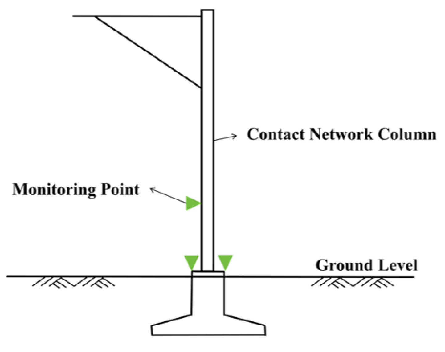
3.1. Field Data Monitoring Methods

To monitor the surface settlement changes during shield tunnel excavation in real time, the research team strategically placed monitoring points along both sides of the railroad (as shown in Figure 3). The placement of these points took into account critical factors, such as the orientation of the railroad line, the depth of the tunnel, and the extent of soil reinforcement, to ensure the representativeness and reliability of the monitoring data. Analysis of the collected data will further validate the effectiveness of the grouting reinforcement through flower tubes and provide a scientific basis for subsequent construction.
The core of the surface settlement monitoring method lies in the construction of a dynamic monitoring system with hierarchical deployment and control, focusing on covering the scope of the influence of shield construction disturbance. Adopting a fully automatic detection system, the monitoring scope extends 30 m outward from the tunnel axis as the center, in which high-density points (3 m spacing) are used within 6 m of the outer wall of the tunnel structure, and measurement points are set up in the peripheral sections at a spacing of 5 m, forming a gradient monitoring network from dense to sparse. The monitoring object covers the rail surface, contact network pillars, and other key facilities; the rail surface measurement points are marked with red paint and numbered uniformly, and the contact network pillars are implemented with refined monitoring (3 measurement points per pillar), as shown in Figure 4. The monitoring frequency is dynamically adjusted according to the construction stage: the conventional frequency is adopted before crossing (1 time/30 min), the peak frequency is encrypted to the peak frequency (1 time/10 min) during the period of crossing, and the attenuation adjustment period is experienced after the crossing (1 time/30 min is maintained for 1 week, and then it is changed to 1 time/h), which forms a three-level response mechanism of ‘prevention-warning-tracking’. In the process of implementation, it is necessary to establish a coordinated monitoring mechanism with the operator of the existing line, covering the whole process of construction disturbance before the 30 m impact zone to the stability period of 3–6 months after the work, through the automated monitoring system to continuously collect the tunnel settlement, convergence, and track surface deformation data until all the monitoring indicators converge to the norm-allowed thresholds. The system realizes the visual control of settlement risk in the whole cycle of shield construction by means of spatial hierarchical deployment and control, time–frequency dynamic adjustment, and multi-source data fusion.

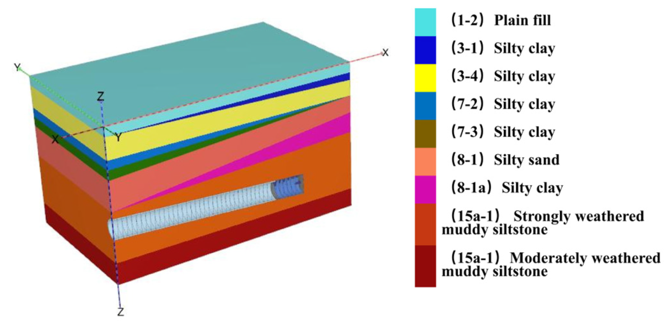
3.2. Numerical Simulation Modeling

3.2.1. Model Assumptions

To investigate the reinforcement effect of diaphragm walls in shield tunnels under flower tube grouting conditions and to enhance computational efficiency through model simplification, this study adopts the following assumptions:
(1)
The shield tunnel lining is idealized as an equivalent homogeneous circular structure, disregarding internal structural details.
(2)
The seepage effects of pore water are neglected, focusing solely on the mechanical behavior of the soil.
(3)
Geological conditions within the study area are assumed to be homogeneously distributed but stratified according to actual geological data, with the physical and mechanical parameters of each soil layer determined by both field and laboratory tests.
(4)
The physical–mechanical properties of grouting materials and soil are treated as constant values, without considering their time-dependent characteristics.
(5)
The model boundary is sufficiently distant from the tunnel to minimize boundary effects on the calculation results.
(6)
The initial stress field is generated exclusively by the self-weight of the soil, excluding other external forces.

3.2.2. Design of Working Conditions

Two working conditions were designed in this study to comparatively analyze the effects of different reinforcement measures on surface settlement:
(1)
No reinforcement working condition: no soil reinforcement measures are taken during tunnel excavation.
(2)
Flower tube grouting reinforcement condition: A single row of flower tube grouting reinforcement is used within 30 m above and on both sides of the centerline of the tunnel, with a grouting depth of 24 m and a grouting interval of 9 m. The tunnel is reinforced with a single row of flower tube grouting reinforcement.
Through numerical simulation, this study compares, in detail, the change rules of tunnel force and surface settlement under the two conditions to evaluate the effect of flower tube grouting reinforcement.
Based on the stratigraphic information of the study area, numerical modelling of the actual soil conditions was carried out in this study using PLAXIS 3D software. The soil body was modelled using the H-S small-strain principal model, and the soil body was initially modelled as a rectangular body with dimensions of 84.5 m (length) × 50 m (width) × 50 m (height). In the numerical simulation, an elastic model is used for the pipe sheet, grouting material and shield shell, and a Mohr–Coulomb model is used for the soil body. According to the above parameters, the soil layer was set up in this study using PLAXIS 3D software. The specific steps are as follows: firstly, the distribution of each soil layer is set according to the information of borehole location and soil burial depth; secondly, the data of borehole location is inputted in combination with the function of the software to accurately reflect the actual geological conditions. Through the above steps, the distribution of underground soil layers was successfully simulated in this study.
A shield tunnel with a diameter of 6.2 m is arranged in the model, and the tunnel boring length is set to 66 m, with 1.5 m boring each time, totaling 44 rings. In order to combine with the actual project, the tunnel modeling direction is set as downward-sloping, and the angle with the x-axis horizontal direction is 4°. Considering the symmetry of surface settlement, only half of the tunnel structure is modeled in this study to simplify the calculation and improve efficiency. Finally, the numerical simulation structure built in PLAXIS 3D software is shown in Figure 5. The depths of the boreholes corresponding to the soil layers are shown in Table 3.
According to the actual construction process of the tunnel, the numerical simulation mainly includes two parts: surface grouting reinforcement and shield tunneling. In the simulation process, a 1.5 m wide ring of tubes is used as a step, from excavation to complete penetration. The specific steps are as follows: firstly, grouting reinforcement is carried out, and the parameters of the reinforced soil body are used in the numerical simulation; secondly, the soil layer distribution, cell structure, and grid division are defined; and finally, the construction process is simulated in phases, including the steps of soil excavation, pipe sheet installation, and grouting reinforcement.

4. Results of the Study

In order to investigate the effect of grouting reinforcement on surface settlement, this study adopts numerical simulation and an actual monitoring data comparison method to analyze the difference in surface settlement between two unreinforced and reinforced conditions, and it discusses the change rule of key factors such as grouting pressure, soil bin pressure, and tunnel depth before as well as after reinforcement. The specific analysis steps are as follows: select four monitoring points in the unreinforced section, analyze the surface settlement pattern, and draw the settlement curve; select the same location of the monitoring points in the reinforced section with the same topography, obtain the surface settlement data, and compare them with the unreinforced section to summarize the pattern.

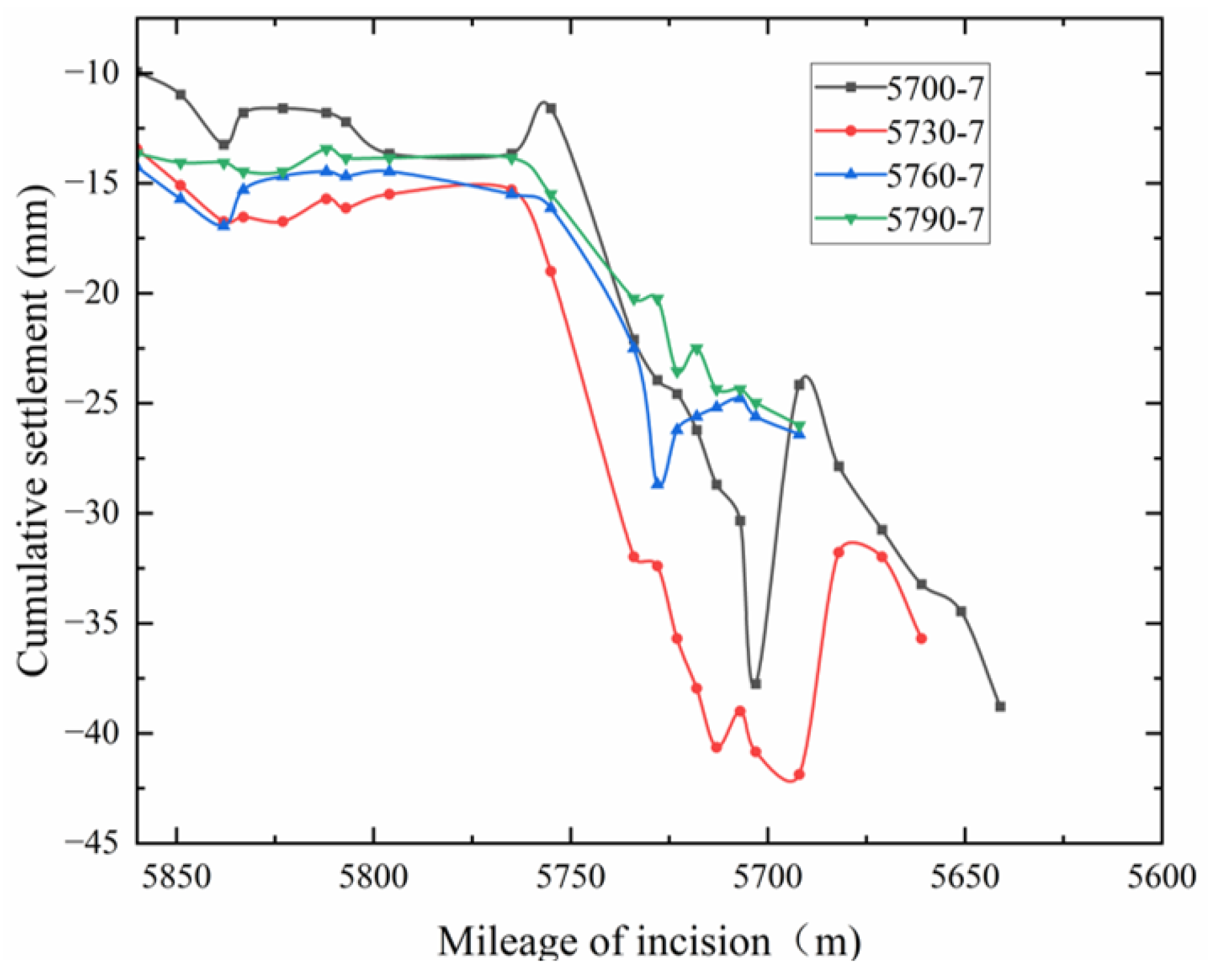
4.1. Unreinforced Surface Settlement Analysis

In the unreinforced section, the shield tunnel boring process will inevitably cause ground movement, which will lead to surface settlement. If the settlement is too large, it may cause serious impacts on the neighboring buildings and the environment, so the construction parameters need to be strictly controlled. In this study, four monitoring points (mileage 5700, 5730, 5760, and 5790) above the centerline of the tunnel in the unreinforced section are selected to analyze the change rule of surface settlement. The horizontal coordinate is the position of the cutter plate incision during shield tunnel excavation, and the vertical coordinate is the amount of surface settlement, and the variation in settlement with shield tunneling is shown in Figure 6.
As can be seen from Figure 6, the change in surface settlement during shield tunneling can be divided into the following stages: when the cutter disk is close to the measurement point, the soil in front of the cutter disk may be slightly deformed due to the cutter disk perturbation and the effect of the soil silo pressure, which may be manifested as a bulge or settlement. If there is a bulge, it may be due to the pressure of the soil bin; if there is settlement, it may be caused by soil disturbance. As the cutter disk approaches the measurement point, the change in surface displacement gradually increases; when the cutter disk leaves the measurement point, the displacement continues to increase. When the shield tail is close to the measurement point, the surface settlement may further increase due to the shield tail detachment, but the synchronized grouting will compensate for part of the settlement, and even a slight bulge may occur if the grouting pressure and the grouting volume are larger. When the shield tail moves away from the measurement point, the surface displacement gradually stabilizes. In addition, due to the influence of the measurement time interval, the flattening section of the cumulative displacement curve at some measurement points is not obvious. The above analysis reveals the dynamic change law of surface settlement during shield excavation, which provides an important basis for the subsequent analysis of reinforcement effect.

4.2. Numerical Modeling of Uncemented Surfaces

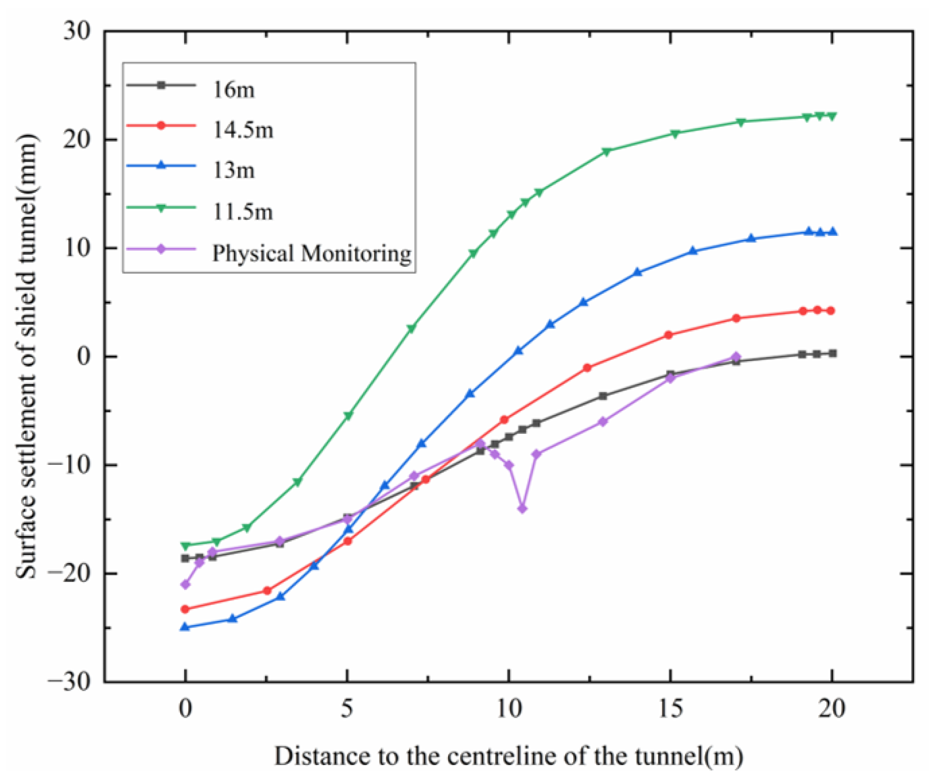
4.2.1. Different Tunnel Depths in Unreinforced Soil

In order to further verify the influence of different shield tunnel burial depths on the surface settlement, the original field data are modified to verify the influence of tunnel burial depth on the surface settlement of the shield tunnel under the rest of the working conditions, and the field inspection data are added to compare and analyze them with the numerical simulation data, and the settlement change diagrams are plotted, as shown in Figure 7. The relevant working condition parameters are shown in Table 4.
Figure 7 shows that when the burial depth is within 13 m, the surface settlement gradually increases with the increase of the shield tunnel depth. When the burial depth is more than 13 m, the surface settlement of the shield tunnel decreases with the increase in the surface depth. Combining these four cases, when the tunnel depth is 16 m, the impact on the surface settlement is relatively small, and the trend of the field monitoring data is more consistent, so the numerical simulation can be a better prediction of the trend of the substantive surface settlement.

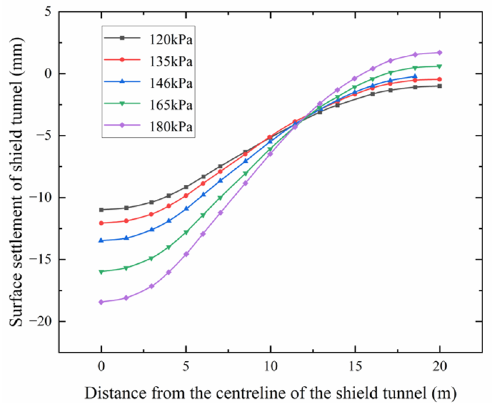
4.2.2. Different Soil Bin Pressures in Unreinforced Soil

In order to further verify the trend in the influence of different soil compartment pressures on the change in surface settlement during shield tunnel excavation under the unreinforced condition of the shield tunnel, five working conditions, as shown in Table 5, were set up, and the corresponding surface settlement change graphs were plotted, as shown in Figure 8.
By analyzing Figure 8, the pressure of the soil bin during the excavation of the shield machine has a certain influence on the amount of surface settlement of the shield tunnel, when other factors are constant. Since the tunnel excavation direction has an angle of −4° with the horizontal plane, it leads to a certain downward pressure on the soil in front of the cutter plate. Through analysis, the amount of soil settlement above the front of the cutter plate continues to increase as the pressure of the soil bin increases. However, when the distance from the centerline of the shield tunnel is equal to three times the tunnel diameter, the surface settlement at each observation point tends to be almost the same, and at this time, the effect of the size of the soil compartment pressure value on the surface settlement is relatively small. Comparing the surface settlement curves of the soil in front of the cutter plate of the shield machine under five different soil compartment pressures, it can be found that when the pressure of the soil compartment reaches 146 kPa, the change in surface settlement is more stable. It being too small will affect the construction, and it being too large will increase the value of the surface settlement of the soil in front of the cutter plate.

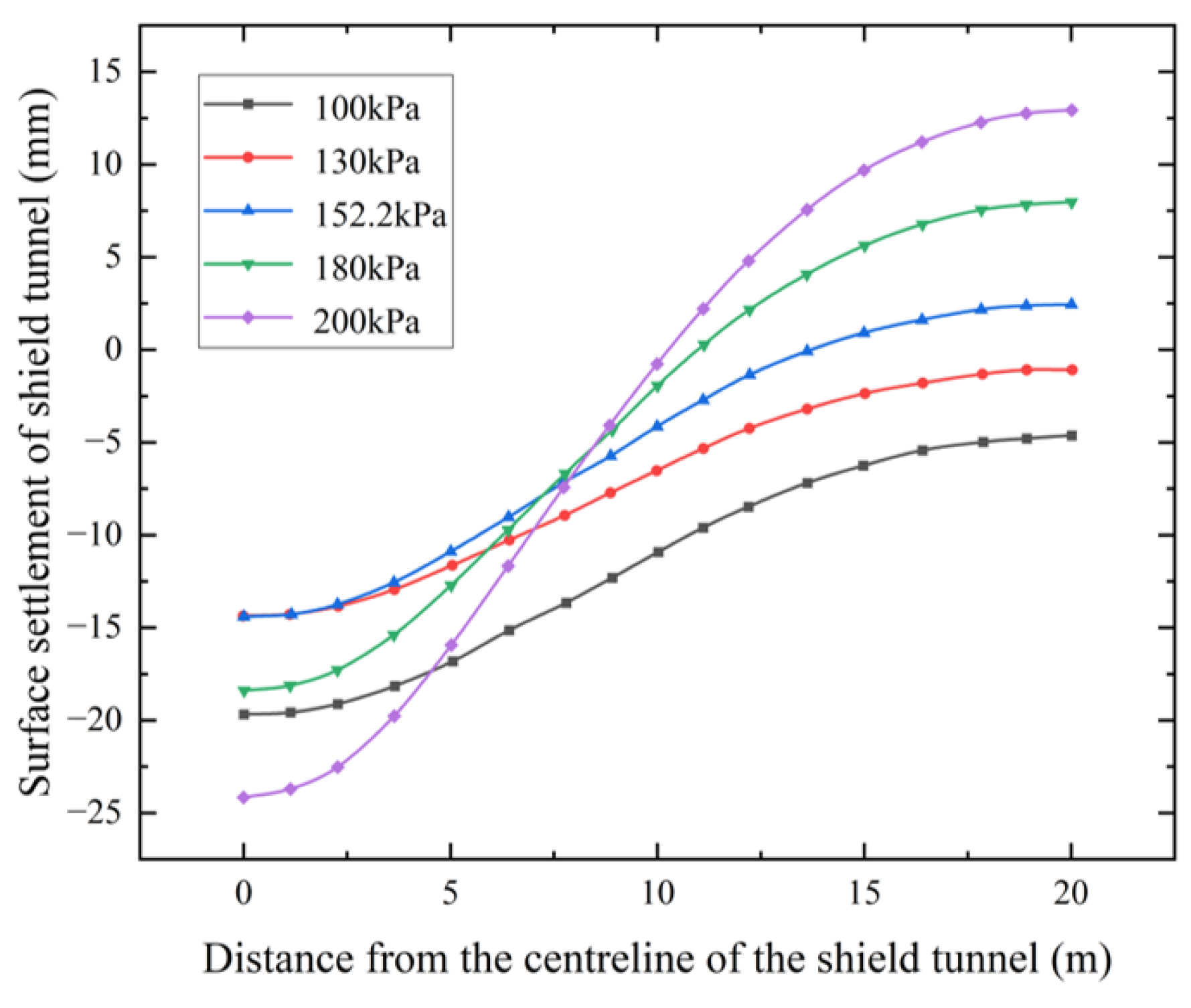
4.2.3. Different Grouting Pressures in Unreinforced Soil

In order to investigate the effect of different grouting pressures on the amount of surface settlement in the shield tunnel during shield tunnel excavation under the unreinforced state of the ground surface, five working conditions, as shown in Table 6, are set up, and numerical simulation is carried out to draw the variation in surface settlement, as shown in Figure 9.
By analyzing Figure 9, when the grouting pressure is less than 152.2 kPa, the maximum settlement value of the ground surface decreases with the increase in the grouting pressure. When the grouting pressure is too high, the maximum ground settlement value increases with the increase in grouting pressure. A certain degree of surface uplift occurs at a location three times the tunnel diameter from the tunnel centerline. In addition, the maximum and minimum difference in the surface settlement values gradually increase with the gradual increase in the grouting pressure. When the grouting pressure is 152.2 kPa, the change in surface settlement is relatively small. According to the numerical simulation cloud diagram and the change in the surface settlement curve, the optimum grouting pressure for this section should be selected near 152.2 kPa. Combined with the field data, the average value of grouting pressure in this interval section is about 152.2 kPa, and the numerical simulation and field data match well.

4.3. Analysis of the Amount of Settlement on the Reinforced Surface

In order to investigate the control effect of grouting reinforcement on surface settlement, this study selected a reinforced section with similar topography to the unreinforced section for surface settlement monitoring. Three monitoring points (mileage 4330, 4342, and 4352) were arranged above the centerline of the shield tunnel to analyze the variation rule of surface settlement. The horizontal coordinate is the position of the cutter plate incision during shield tunnel excavation, the vertical coordinate is the amount of surface settlement, and the change in settlement with shield tunneling is shown in Figure 10.
As can be seen from Figure 10, the rule of change in surface settlement along the shield axis in the reinforced section is as follows: when the shield cutout approaches the location of the measurement point from a distance, the measurement point appears to be slightly elevated, which may be due to the joint action of the soil chamber pressure and grouting pressure; when the shield cutout approaches the measurement point, the surface begins to settle and tends to converge, and the settlement curve shows a period of gentle change; after the gentle section, the surface settlement again increases and a period of gentle change then appears. After the gentle section, the amount of surface settlement increases again, followed by a period of gentle changes. When the shield tail is close to the measurement point, the surface settlement reaches a very small value; at this time, the shield tail may cause a large settlement, but under the effect of synchronized grouting, the surface settlement partly rebounds and finally tends to converge. The alternation of gentle and steep sections in the settlement curve is mainly due to the combined effect of the taper of the shield machine itself and the grouting reinforcement. In addition, due to the influence of the measurement time interval, the gentle section of the cumulative displacement curve at some measurement points is not obvious.

4.4. Numerical Simulation Analysis of the Amount of Consolidated Surface Settlement

4.4.1. Different Tunnel Depths in Reinforced Soils

In order to verify the effect of different tunnel depths on the amount of surface settlement after soil grouting reinforcement, numerical simulations were carried out using several working conditions, as shown in Table 7. The results after simulation are shown in Figure 11.
By analyzing Figure 11, the maximum value of surface uplift shows a gradual decrease with the gradual increase in burial depth. When the burial depth of the underground tunnel increases, the settlement of the ground surface is controlled within the range of −1 mm to 2.5 mm. This indicates that after the soil body is reinforced by grouting the tunnel, burial depth has some effects on the settlement of the soil body above. However, these effects are not obvious. When the burial depth reaches 35 m, the settlement of the surface is further limited to between −0.5 mm and 1.5 mm, which has the best effect. When the distance from the center of the tunnel reaches 15 m, the change in surface settlement tends to be constant, because shield tunnel excavation causes a negligible change in surface settlement when the distance from the centerline of the tunnel reaches three times the diameter of the tunnel. Through comparative analysis, the grouting reinforcement of the soil body can appropriately reduce the influence of the tunnel burial depth on the change in surface settlement.

4.4.2. Different Soil Bin Pressures in Reinforced Soils

In order to investigate the effect of different shield tunnel soil compartment pressure sizes on the settlement of the roadbed after soil reinforcement, corresponding models were established with PLAXIS 3D software, and the parameters of each model are shown in Table 8. The change in the surface settlement of its shield tunnel is shown in Figure 12.
By analyzing Figure 12, it can be concluded that when the soil bin pressure is in the range of 120 kPa to 180 kPa, the amount of surface settlement or bulge shows a slight increasing trend with the increase in the soil bin pressure. The surface settlement of the shield tunnel was effectively controlled within −1 mm to 1.5 mm, and the magnitude of the earth silo pressure had a small effect on the surface settlement values.

4.4.3. Different Grouting Pressures in Reinforced Soils

In order to investigate the effect of different shield tunnel grouting pressure sizes on roadbed settlement after soil reinforcement, corresponding models were established with PLAXIS 3D software, and the parameters of each model are shown in Table 9. The plotted changes in surface settlement are shown in Figure 13.
Through Figure 13, when the grouting pressure was gradually increased in the range of 350 kPa to 450 kPa, the surface settlement or uplift of the soil above the grouting ring showed a slight increasing trend. However, the surface settlement of the shield tunnel was strictly controlled within the variation range of −1 mm to 1.5 mm, which reflects the effective control of the settlement amount during the grouting process. The magnitude of the grouting pressure has less influence on the surface settlement value, which indicates that the grouting reinforcement of the soil above the shield plays a very important role.

5. Analysis of Results

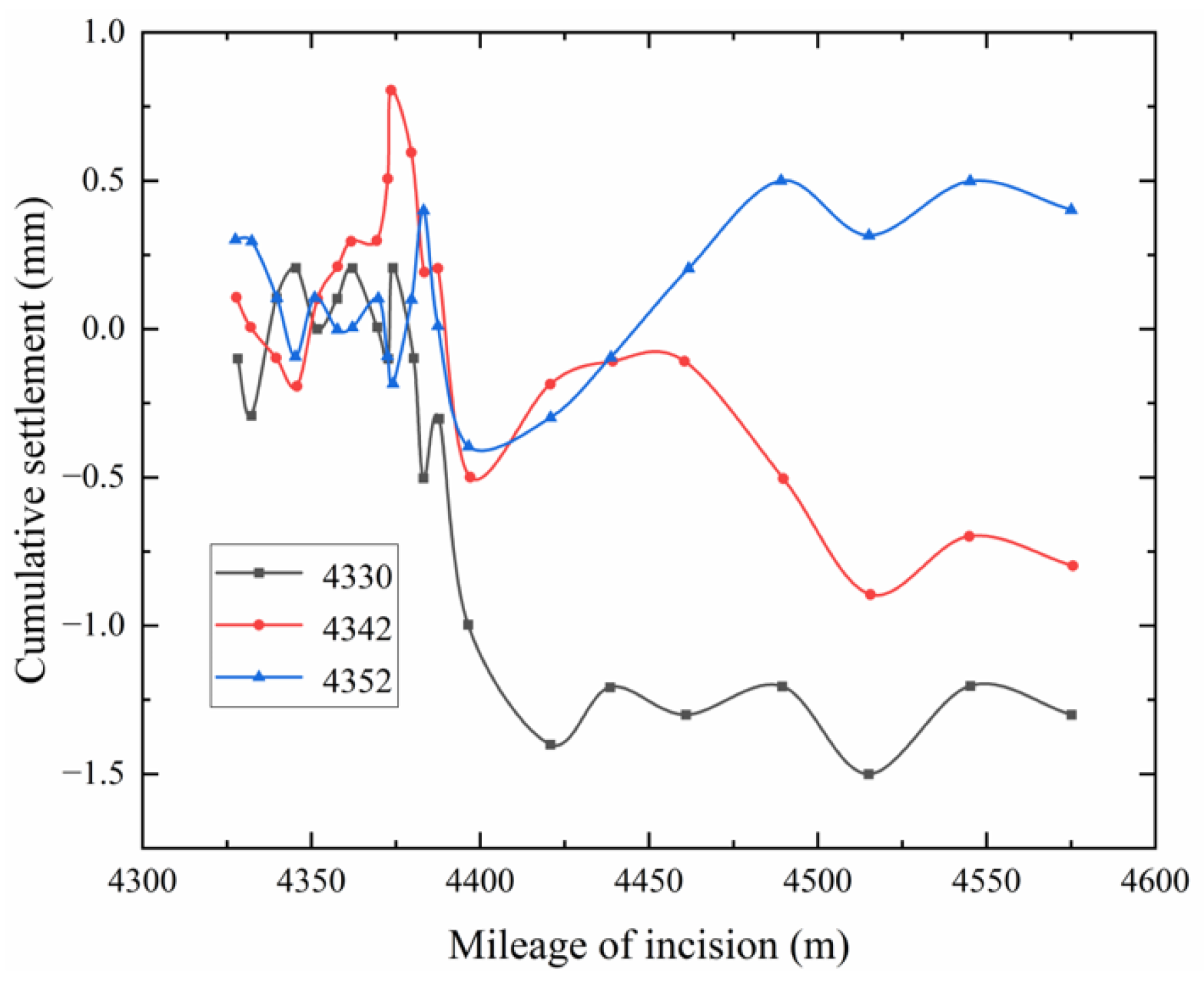
5.1. Comparative Analysis of Field Test Data

Comparing the changes in surface settlement in Figure 6 (unreinforced section) and Figure 10 (reinforced section), it can be clearly found that the surface settlement in the reinforced section is controlled within 3 mm, which fully meets the specification requirements for the shield tunnel underneath the subway line; compared with the unreinforced section, the surface settlement in the reinforced section has been reduced by about 92%, which indicates that flower tube grouting reinforcing has a remarkable effect on the control of the surface settlement. The above analysis shows that flower tube grouting reinforcement can effectively reduce the surface settlement, significantly improve the stability of the soil body, and provide a reliable technical guarantee for the shield tunnel to penetrate the complex stratum.

5.2. Comparative Analysis of Numerical Simulation Data
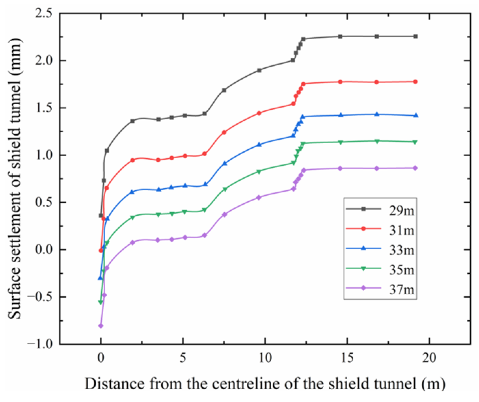
Based on the numerical simulation results, the following main conclusions can be drawn:
(1)
As the burial depth of the shield tunnel changes, the surface settlement also varies. Specifically, as the burial depth increases, the soil arch effect at the surface gradually diminishes. Within the burial depth range of 29 m to 37 m, surface settlement is controlled between −1.0 mm and 2.5 mm, indicating a relatively minor change. Moreover, beyond three times the tunnel diameter, surface settlement decays to the stability threshold of ±0.2 mm, with changes in surface settlement gradually stabilizing.
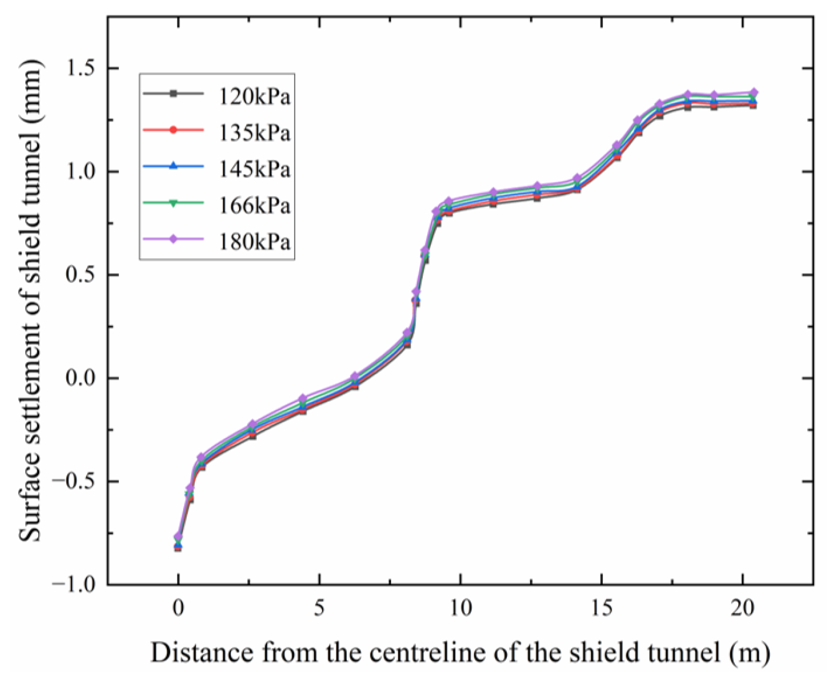
(2)
By comparing the effects of silo pressure on surface settlement, it is observed that when silo pressure ranges from 120 kPa to 180 kPa, surface settlement remains between −1.0 mm and 1.5 mm. The variation in surface settlement due to changes in silo pressure is within ±0.2 mm, suggesting that after grouting and strengthening of the surface soil, the impact of silo pressure on surface settlement becomes almost negligible.
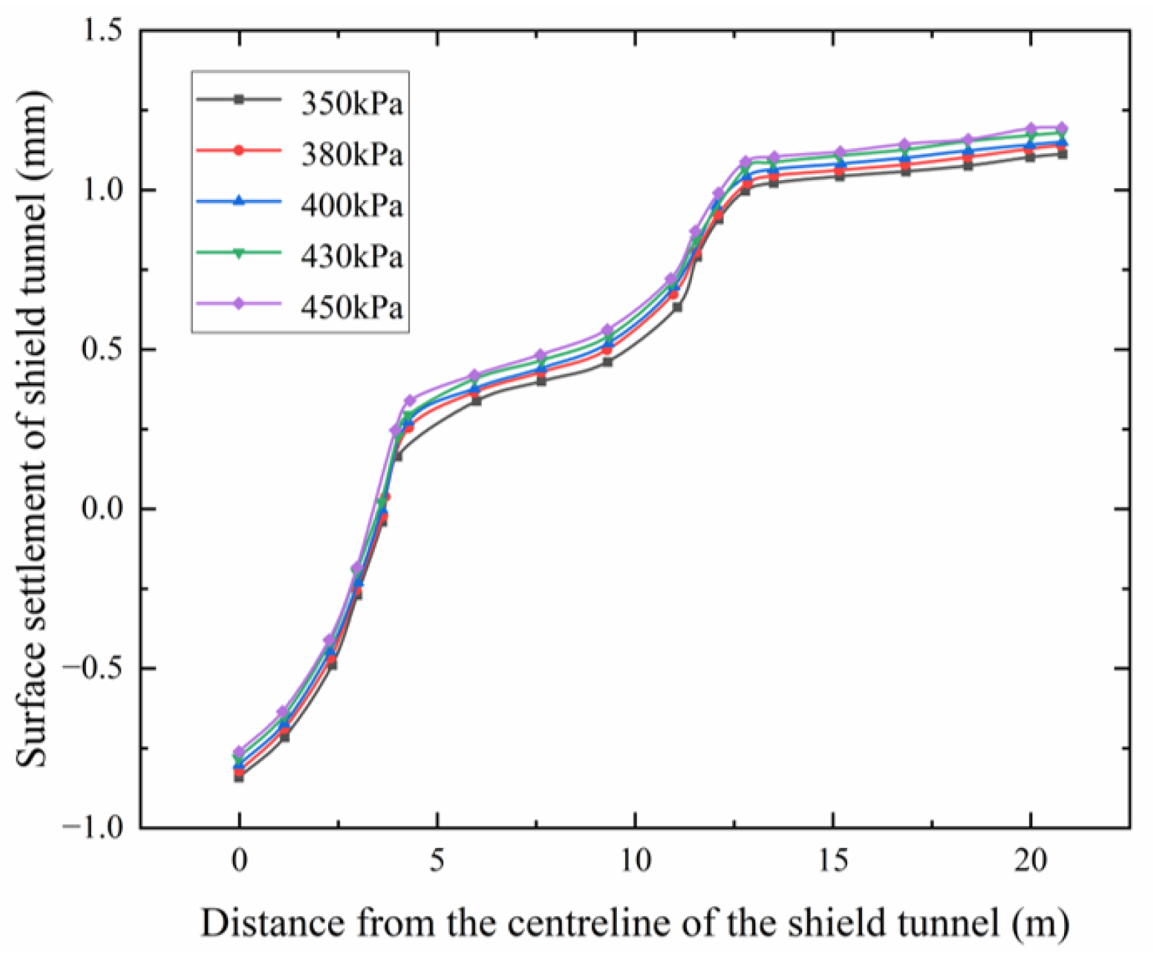
(3)
When grouting pressure is between 350 kPa and 450 kPa, surface settlement is maintained between −1.0 mm and 1.5 mm. Changes in grouting pressure result in surface settlement variations within ±0.2 mm, indicating that after grouting and reinforcing the surface soil, the influence of grouting pressure on surface settlement is nearly negligible.
(4)
After the soil above the shield tunnel is grouted and reinforced, the factors of tunnel depth, grouting pressure, and soil chamber pressure have less influence on the change in surface settlement during shield tunnel excavation, and the effect of early grouting and reinforcement of the soil on the reduction in surface settlement is significant.

5.3. Future Prospects

With the development of urban underground space to deeper and denser development, shield tunnel grouting control and settlement inhibition technology will face higher precision requirements. Intelligent regulation of grouting parameters based on multi-physical field coupling is the core breakthrough direction: on the one hand, it is necessary to establish a real-time feedback model of the evolution of grouting pressure–diffusion radius–soil stiffness, combined with distributed optical fiber and microseismic monitoring data, to achieve the dynamic evaluation of grouting effect; on the other hand, artificial intelligence-driven grouting decision-making systems (such as parameter optimization based on an LSTM network) can break through the limitations of traditional empirical formulas and achieve a settlement prediction error of <5% in complex strata. In addition, the development of low-viscosity and high-strength quick-consolidation grouting materials (e.g., nano-silica modified slurry) is expected to improve the uniformity of reinforcement while reducing injection resistance, and 3D printing directional grouting technology may accurately repair the weak areas of the soil body. Future research should focus on the synergistic innovation of construction–monitoring–materials technology and achieve whole-life-cycle settlement control through a digital twin platform to provide theoretical support for the construction of smart tunnels.

6. Conclusions

Based on the PLAXIS 3D numerical simulation platform, this study systematically investigates the surface settlement characteristics of unreinforced soil and grout-reinforced soil during shield tunnel construction, focusing on the influence of tunnel burial depth, grouting pressure, and soil bin pressure on the surface settlement. Through comparative analysis, the following main conclusions are drawn:
(1)
Flower pipe grouting reinforcement technology demonstrates significant efficacy in controlling surface settlement. Research findings indicate that, compared to unreinforced conditions, the implementation of grouting reinforcement reduces average surface settlement by 92%, with maximum settlement controlled within 3 mm. This evidence provides an effective solution for mitigating surface settlement when shield tunnels traverse sensitive areas such as long-distance railroads.
(2)
The numerical simulation method demonstrates high reliability in predicting surface settlement caused by shield tunnel construction. The discrepancy between the simulation results and on-site monitoring data is maintained within ±0.5 mm, thereby validating the accuracy of the numerical model and providing a robust technical approach for predicting surface settlement in similar projects.
(3)
Under unreinforced conditions, surface settlement exhibits the following trends: tunnel depth is negatively correlated with surface settlement, decreasing by approximately 0.15 mm for every 1 m increase in depth; soil chamber pressure is positively correlated with surface settlement, increasing by approximately 0.08 mm for every 10 kPa increase in pressure; grouting pressure has a critical value of around 400 kPa. Below this critical value, surface settlement decreases as grouting pressure increases; however, once the grouting pressure exceeds this critical value, surface settlement increases with further increases in grouting pressure.
(4)
Under flower pipe grouting reinforcement conditions, the influence of tunnel depth, grouting pressure, and soil compartment pressure on surface settlement is markedly diminished, with the degree of impact reduced by approximately 85–95% relative to unreinforced conditions. These results suggest that grouting reinforcement measures can effectively mitigate the effects of construction parameter variations on surface settlement, thereby providing enhanced stability and reliability for shield tunnel construction in sensitive regions.
(5)
When the shield tunnel passes through a long-distance railway group, surface grouting reinforcement can effectively reduce the impact caused by shield tunnel excavation, so this engineering method can be usefully and effectively applied to similar projects in the future.

Author Contributions

Q.M., resources, supervision, and funding acquisition; X.Z., conceptualization, methodology, and writing—original draft; H.S., supervision and writing—review and editing. All authors have read and agreed to the published version of the manuscript.

Funding

The authors are grateful for the financial support of the National Natural Science Foundation of China (No. 52478338, No. 52078194), the National Young Top-notch Talent of Ten Thousand Talents Program, the Science Fund for Distinguished Young Scholars of Hubei Province (2022CFA043), the Young Top-notch Talent Cultivation Program of Hubei Province, the Outstanding Young and middle-aged Science and Technology Innovation Team of colleges and universities in Hubei Province (No. T2022010), and the Innovation Demonstration Base of Ecological Environment Geotechnical and Ecological Restoration of Rivers and Lakes (No. 2020EJB004).

Institutional Review Board Statement

Not applicable.

Informed Consent Statement

Not applicable.

Data Availability Statement

The data presented in this article are available within the article.

Conflicts of Interest

The authors declare no conflict of interest.

References

  1. Liu, D.; Zhang, X.; Tang, Y.; Jin, Y.; Cao, K. Study on the Impact of Different Pile Foundation Construction Methods on Neighboring Oil and Gas Pipelines under Very Small Clearances. Appl. Sci. 2024, 14, 3609. [Google Scholar] [CrossRef]
  2. Liang, R.; Xia, T.; Hong, Y.; Yu, F. Effects of above-crossing tunnelling on the existing shield tunnels. Tunn. Undergr. Space Technol. 2016, 58, 159–176. [Google Scholar]
  3. Li, X.; Yuan, D. Development of the safety control framework for shield tunneling in close proximity to the operational subway tunnels: Case studies in mainland China. Springerplus 2016, 5, 527. [Google Scholar]
  4. Liu, B.; Yu, Z.; Han, Y.; Wang, Z.; Zhang, R.; Wang, S. Analytical solution for the response of an existing tunnel induced by above-crossing shield tunneling. Comput. Geotech. 2020, 124, 103624. [Google Scholar]
  5. Mi, B.; Xiang, Y. Model experiment and calculation analysis of excavation-seepage stability for shallow shield tunneling in sandy ground. Rock Soil Mech. 2020, 41, 4. [Google Scholar]
  6. Xu, Q.; Zhu, H.; Ma, X.; Ma, Z.; Li, X.; Tang, Z.; Zhuo, K. A case history of shield tunnel crossing through group pile foundation of a road bridge with pile underpinning technologies in Shanghai. Tunn. Undergr. Space Technol. 2015, 45, 20–33. [Google Scholar]
  7. Zhang, Z.; Huang, M. Geotechnical influence on existing subway tunnels induced by multiline tunneling in Shanghai soft soil. Comput. Geotech. 2014, 56, 121–132. [Google Scholar]
  8. Fang, Q.; Zhang, D.; Li, Q.; Wong, L.N.Y. Effects of twin tunnels construction beneath existing shield-driven twin tunnels. Tunn. Undergr. Sp. Technol. 2015, 45, 128–137. [Google Scholar]
  9. Wang, Z.; Zhang, K.; Wei, G.; Li, B.; Li, Q.; Yao, W. Field measurement analysis of the influence of double shield tunnel construction on reinforced bridge. Tunn. Undergr. Space Technol. 2018, 81, 252–264. [Google Scholar]
  10. Lin, X.; Chen, R.; Wu, H.; Cheng, H. Deformation behaviors of existing tunnels caused by shield tunneling undercrossing with oblique angle. Tunn. Undergr. Space Technol. 2019, 89, 78–90. [Google Scholar]
  11. Shi, C.; Cao, C.; Lei, M.; Peng, L.; Ai, H. Effects of lateral unloading on the mechanical and deformation performance of shield tunnel segment joints. Tunn. Undergr. Space Technol. 2016, 51, 175–188. [Google Scholar]
  12. Elwood, D.E.Y.; Martin, C.D. Ground response of closely spaced twin tunnels constructed in heavily overconsolidated soils. Tunn. Undergr. Space Technol. 2016, 51, 226–237. [Google Scholar]
  13. Fargnoli, V.; Boldini, D.; Amorosi, A. Twin tunnel excavation in coarse grained soils: Observations and numerical back-predictions under free field conditions and in presence of a surface structure. Tunn. Undergr. Space Technol. 2015, 49, 454–469. [Google Scholar]
  14. Zheng, H.; Li, P.; Ma, G. Stability analysis of the middle soil pillar for asymmetric parallel tunnels by using model testing and numerical simulations. Tunn. Undergr. Space Technol. 2021, 108, 103686. [Google Scholar]
  15. Yan, B.; Wang, R.; Ding, B.; Dai, F.; Wang, Y. Numerical simulation analysis of tunnel backfill grout based on DEM-FDM coupling and particle inlet. Undergr. Space 2024, 14, 285–299. [Google Scholar]
  16. Zhang, D.; Huang, Z.; Wang, R.; Yan, J.; Zhang, J. Grouting-based treatment of tunnel settlement: Practice in Shanghai. Tunn. Undergr. Space Technol. 2018, 80, 181–196. [Google Scholar]
  17. Zhang, X.; Qin, H.; Xu, Y.; Qu, H.; Chen, C. Performance of an operational shield tunnel due to construction of a large cross-sectional straight-walled arch tunnel above-crossing. Alex Eng. J. 2024, 108, 863–877. [Google Scholar]
  18. Li, Z.; Liu, X.; Wang, J. Elaborate numerical investigation on surcharge-induced mechanical responses and strengthening effects of single-line shield tunnels with typical cross-sections. Tunn. Undergr. Space Technol. 2025, 156, 106237. [Google Scholar]
  19. Zhang, J.; Yu, J.; Li, C.; Liu, Y.; Tian, L.; He, Y.; Zhang, Q. Deformation and Reinforcement of the Existing Tunnel Affected by New Shield Tunnel Construction with Small Clearance. Buildings 2025, 15, 265. [Google Scholar] [CrossRef]
  20. Zhu, T.; Huang, F.; Li, S.; Ouyang, T.; Ying, J.; Zhao, H. Optimization of pre-grouting construction and evaluation of grouting effect in a deeply buried silt-filled shield tunnel. Tunn. Undergr. Space Technol. 2024, 152, 105902. [Google Scholar]
  21. Jin, H.; Yuan, D.; Jin, D.; Wu, J.; Wang, X.; Han, B.; Mao, J. Ground deformation induced by shield tunneling posture in soft soil. Tunn. Undergr. Space Technol. 2023, 139, 105227. [Google Scholar] [CrossRef]
  22. Liao, S.; Liu, J.; Wang, R.; Li, Z. Shield tunneling and environment protection in Shanghai soft ground. Tunn. Undergr. Space Technol. 2009, 24, 454–465. [Google Scholar]
  23. Liang, R.; Kang, C.; Xiang, L.; Li, Z.; Lin, C.; Gao, K.; Guo, Y. Responses of in-service shield tunnel to overcrossing tunnelling in soft ground. Environ. Earth Sci. 2021, 80, 183. [Google Scholar] [CrossRef]
  24. Cao, C.; Shi, C.; Lei, M.; Peng, L.; Bai, R. Deformation Characteristics and Countermeasures of shallow and Large-span Tunnel Under-crossing the Existing Highway in Soft Soil: A Case Study. KSCE J. Civ. Eng. 2018, 22, 3170–3181. [Google Scholar] [CrossRef]
  25. Li, Z.; Chen, Z.; Yang, Y.; Jiang, Y.; Xu, X.; Hu, Q. Deformation characteristics of existing tunnels induced by above-crossing quasi-rectangular shield tunnel. Transp. Geotech. 2024, 45, 101227. [Google Scholar] [CrossRef]
  26. Yang, Y.; Liao, S.; Liu, M.; Wu, D.; Pan, W.; Li, H. A new construction method for metro stations in dense urban areas in Shanghai soft ground: Open-cut shafts combined with quasi-rectangular jacking boxes. Tunn. Undergr. Space Technol. 2022, 125, 104530. [Google Scholar] [CrossRef]
  27. Feng, X.; Wang, P.; Liu, S.; Wei, H.; Miao, Y.; Bu, S. Mechanism and Law Analysis on Ground Settlement Caused by Shield Excavation of Small-Radius Curved Tunnel. Rock Mech. Rock Eng. 2022, 55, 3473–3488. [Google Scholar] [CrossRef]
  28. Yang, X.; Liu, Y.; Liu, K.; Wei, J.; Hu, G.; Pei, S. Application and configuration analysis of electric muck transfer equipment in plateau railway tunnel: A case study in southwest China. Sci. Rep. 2024, 14, 7222. [Google Scholar]
  29. Yang, J.; Zhang, C.; Fu, J.; Wang, S.; Ou, X.; Xie, Y. Pre-grouting reinforcement of underwater karst area for shield tunneling passing through Xiangjiang River in Changsha, China. Tunn. Undergr. Space Technol. 2020, 100, 103380. [Google Scholar]
  30. Jin, D.; Yuan, D.; Li, X.; Zheng, H. Analysis of the settlement of an existing tunnel induced by shield tunneling underneath. Tunn. Undergr. Space Technol. 2018, 81, 209–220. [Google Scholar]
  31. Jallow, A.; Ou, C.; Lim, A. Three-dimensional numerical study of long-term settlement induced in shield tunneling. Tunn. Undergr. Space Technol. 2019, 88, 221–236. [Google Scholar] [CrossRef]
  32. Li, W.; Wen, H. Research on the Construction Mechanics and Stability Control Technology of Expressway Tunnel Based on Numerical Analysis. Eur. J. Comput. Mech. 2024, 33, 461–482. [Google Scholar] [CrossRef]
Figure 1. Technical route.
Applsci 15 04623 g001
Figure 2. Numerical simulation section of Wunan formation railway tunnel underneath the interval.
Applsci 15 04623 g002
Figure 3. Distribution of surface railroads and placement of monitoring points in the simulated interval section.
Applsci 15 04623 g003
Figure 4. Schematic diagram of contact network column monitoring.
Applsci 15 04623 g004
Figure 5. Three-dimensional numerical analysis of the numerical simulation section of the Wunan Formation Railway tunnel underneath the interval.
Applsci 15 04623 g005
Figure 6. Cumulative settlement curves of measurement points 1, 2, 3, and 4 of the unreinforced section.
Applsci 15 04623 g006
Figure 7. Surface settlement of shield tunnel at different burial depths.
Applsci 15 04623 g007
Figure 8. Surface settlement values of shield tunnel under the influence of different soil compartment pressures.
Applsci 15 04623 g008
Figure 9. Surface settlement values of shield tunnel under the influence of different grouting pressures.
Applsci 15 04623 g009
Figure 10. Cumulative settlement curve of measurement points in the reinforced section.
Applsci 15 04623 g010
Figure 11. Surface settlement of shield tunnel at different burial depths after soil reinforcement.
Applsci 15 04623 g011
Figure 12. Surface settlement of shield tunnel under different soil compartment pressures after soil reinforcement.
Applsci 15 04623 g012
Figure 13. Surface settlement of shield tunnel under different grouting pressures after soil reinforcement.
Applsci 15 04623 g013
Table 1. Soil physical parameters.
Designation1-2 Plain Fill Soil3-1 Clay3-4 Silty Clay7-2 Silty Clay7-3 Silty Clay8-1 Silty Sand8-1a Silty Clay
Parameter NameUnit (of Measure)
Soil heavinesskN/m31918.61818.919.22119.4
Modulus of compressionMPa4.19538.56.0166
Poisson’s ratio 0.340.330.360.340.350.30.33
Cohesive forcekN/m212191216232225
Friction angle°81069133115
Table 2. Physical parameters of reinforcement materials.
MaterialsDensity/(kg/m3)Modulus of Elasticity/MPaPoisson’s Ratio
Tube sheet25003.45 × 1040.3
Grouting materialspre-hardening20001.200.3
post-hardening20006.000.4
Shield78502 × 1050.3
Table 3. Settings of drilling information in PLAXIS 3D software.
LayersBorehole-1Borehole-2Borehole-3Borehole-4
MaterialsTop (m)Bottom
(m)
Top
(m)
Bottom (m)Top
(m)
Bottom (m)Top
(m)
Bottom (m)
(1-2) Plain fill0.00−3.200.00−3.200.00−3.500.00−3.50
(3-1) Silty clay−3.20−3.20−3.20−3.20−3.50−6.00−3.50−6.00
(3-4) Silty clay−3.20−10.40−3.20−10.40−6.00−11.30−6.00−11.30
(7-2) Silty clay−10.40−13.40−10.40−13.40−11.30−11.30−11.30−11.30
(7-3) Silty clay−13.40−16.60−13.40−16.60−11.30−11.30−11.30−11.30
(8-1) Silty sand−16.60−26.50−16.60−26.50−11.30−17.00−11.30−17.00
(8-1a) Silty clay−26.50−26.50−26.50−26.50−17.00−23.80−17.00−23.80
(15a-1) Strongly weathered muddy siltstone−26.50−42.90−26.50−42.90−23.80−43.80−23.80−43.80
(15a-1) Moderately weathered muddy siltstone−42.90−50.00−42.90−50.00−43.80−50.00−43.80−50.00
Table 4. Shield parameters for different tunnel depths in Unreinforced Soil.
ProgrammesDepth of Burial of Tunnels (m)Radius of the Tunnel (m)Grouting Pressure (kPa)Pressure on Soil Chamber (kPa)
Scenario 111.53.1152.2146
Scenario 2133.1152.2146
Scenario 314.53.1152.2146
Scenario 4163.1152.2146
Table 5. Shield parameters at different soil compartment pressures in Unreinforced Soil.
ProgrammesDepth of Burial of Tunnels (m)Radius of the Tunnel (m)Grouting Pressure (kPa)Pressure on Soil Chamber (kPa)
Scenario 1163.1152.2120
Scenario 2163.1152.2135
Scenario 3163.1152.2146
Scenario 4163.1152.2165
Scenario 5163.1152.2180
Table 6. Shield parameters at different grouting pressures in Unreinforced Soil.
ProgrammesDepth of Burial of Tunnels (m)Radius of the Tunnel (m)Grouting Pressure (kPa)Pressure on Soil Chamber (kPa)
Scenario 1163.1100146
Scenario 2163.1130146
Scenario 3163.1152.2146
Scenario 4163.1180146
Scenario 5163.1200146
Table 7. Shield parameters at different grouting pressures in Reinforced Soils.
ProgrammesDepth of Burial of Tunnels (m)Radius of the Tunnel (m)Grouting Pressure (kPa)Pressure on Soil Chamber (kPa)
Scenario 1293.1400166
Scenario 2313.1400166
Scenario 3333.1400166
Scenario 4353.1400166
Scenario 5373.1400166
Table 8. Shield parameters at different grouting pressures in Reinforced Soils.
ProgrammesDepth of Burial of Tunnels (m)Radius of the Tunnel (m)Grouting Pressure (kPa)Pressure on Soil Chamber (kPa)
Scenario 1353.1400120
Scenario 2353.1400135
Scenario 3353.1400145
Scenario 4353.1400166
Scenario 5353.1400180
Table 9. Shield parameters at different grouting pressures in Reinforced Soils.
ProgrammesDepth of Burial of Tunnels (m)Radius of the Tunnel (m)Grouting Pressure (kPa)Pressure on Soil Chamber (kPa)
Scenario 1353.1350166
Scenario 2353.1380166
Scenario 3353.1400166
Scenario 4353.1430166
Scenario 5353.1450166
Disclaimer/Publisher’s Note: The statements, opinions and data contained in all publications are solely those of the individual author(s) and contributor(s) and not of MDPI and/or the editor(s). MDPI and/or the editor(s) disclaim responsibility for any injury to people or property resulting from any ideas, methods, instructions or products referred to in the content.

