Article

Analysis of Different Guide Elements’ Designs in Hydraulic Cylinders

1
Faculty of Mechanical Engineering, University of Ljubljana, Aškerčeva cesta 6, 1000 Ljubljana, Slovenia
2
Slovenian National Building and Civil Engineering Institute, Dimičeva 12, 1000 Ljubljana, Slovenia
3
Faculty of Mechanical Engineering, University of Maribor, Smetanova ulica 17, 2000 Maribor, Slovenia
*
Author to whom correspondence should be addressed.
Appl. Sci. 2025, 15(9), 4738; https://doi.org/10.3390/app15094738
Submission received: 18 March 2025 / Revised: 9 April 2025 / Accepted: 18 April 2025 / Published: 24 April 2025
(This article belongs to the Section Mechanical Engineering)

Abstract

:
In this study, the frictional behaviours of three different guide elements—guide rings, labyrinth seals, and hydrostatic bearings—in hydraulic cylinders is investigated experimentally. A modular, double-acting hydraulic cylinder was designed to compare these three different design elements under different pressures (0 bar, 120 bar, and 240 bar), velocities, and radial loads. The results show that the guide rings exhibit the highest friction, especially at high pressures. Labyrinth seals exhibit significantly lower friction and extend the service life of the components. Hydrostatic bearings allow low friction but require precise control of the fluid, which limits their use. The results provide practical guidelines for selecting guide elements and optimising the friction performance, durability, and efficiency of hydraulic systems. We found that the best solution from the points of view of design, friction, and economics is to use labyrinth seals as guiding elements for the fast reciprocal moving rods of hydraulic cylinders.

1. Introduction

Hydraulic and/or pneumatic components are important for various machines where high loads, redundancy, and rigidity are required in the system, especially in agriculture, forestry, automotives, aviation, construction, etc. Various types of oils or water-based fluids—water, ionic fluids, etc.—are commonly used for power transmission in hydraulics [1,2,3,4,5,6], while air is used in pneumatics [7]. Hydraulics are widely used in many industries because they have many advantages, such as simple operation, mobility, high power density, fast automation, good overload protection, and fast change of motion [8,9,10,11,12,13,14,15,16,17,18]. Their disadvantages are their relatively low efficiency compared to mechanical drives, their possible internal losses, the compressibility of the fluid, the high associated working and manufacturing costs, their relatively expensive maintenance, etc. [7,19,20,21]. The energy stored in a pressurised fluid is converted into a linear or rotary mechanical movement. Almost all types of hydraulic cylinders (HCs), regardless of the guide elements, use elastomer seals that prevent leakage between the chambers or the environment [22,23,24,25,26,27]. Seals and wipers are used to prevent contaminants such as solid particles and water from entering the hydraulic cylinder. The seals cause friction and wear on the contacting components, and if the damage is large enough, leakage will occur. Leaks can lead to a reduction in volumetric efficiency and damage, as well as pollution [14,28,29,30,31,32,33,34,35,36]. The frictional force between seals and mating surfaces in relative sliding motions has a significant influence on the performance, reliability, sliding behaviour, and wear of seals/mating surfaces [37,38]. The system pressure can significantly influence the frictional behaviour of different guide elements, impacting overall performance and wear. The choice of guide element has a great influence on the pressure distribution. Figure 1 shows the efficiency and pressure distribution for different types of guide elements [39]. An incorrect choice of seal material or seal geometry, insufficient surface roughness, and lubrication can lead to inadequate seal performance or other tribological factors resulting in high friction, poor seal performance, and low system efficiency, as well as higher operating costs [37,40,41,42,43]. Conversely, reducing frictional forces improves the performance and efficiency of hydraulic cylinders (or other components), extends their service life, and expands their application range in a variety of industrial environments [37,42].
Belforte et al. [37] described the design of a new test rig for measuring frictional forces in pneumatic components and seals. Azzi et al. [40] proposed an experimental study on the influence of different seal geometries in pneumatic cylinders and operating conditions on friction behaviour. The experimental tests were carried out on industrial, commercially available pneumatic cylinders, whereby pistons and rod seals were tested separately in order to investigate the frictional behaviour of the individual seals. Mazza et al. [41] presented an analytical model, with its experimental validation of a pneumatic differential cylinder and a double-acting hydraulic cylinder with a double piston rod. Ambu et al. [42] proposed a redesign of the interface between the front head and the guide bearing of a linear pneumatic cylinder. The design changes were made using finite element analysis. In [14,37,40,41,42], the authors dealt with the frictional force of the seals of pneumatic cylinders. The objective of this paper is to evaluate the frictional force of a hydraulic cylinder with different designs of the guide elements (guide ring, labyrinth seal, and hydrostatic bearing) used in industry at different pressures and radial loads and to consider them as a whole.

2. Design and Methods

In the study, a modular double-acting hydraulic cylinder with double piston rod was designed and manufactured, allowing the comparison of three different ways of guiding the piston rod. The main dimensions were ϕ 50/40 × 500 (bore diameter/piston diameter × stroke). The head of the hydraulic cylinder was separately designed for each guide element. To minimise variability, the same piston rod wipers (Table 1) and rod seals (Table 2) were used, and the same guide lengths and overall dimensions were used for all guide types.

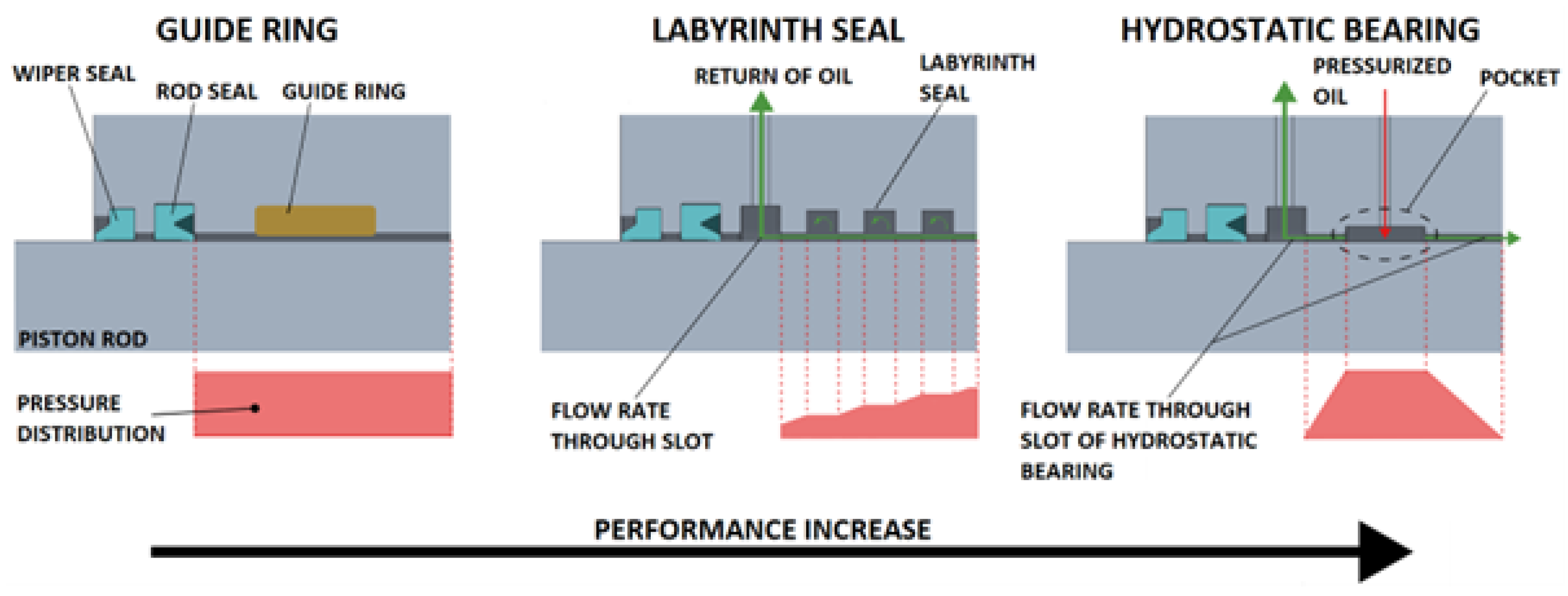
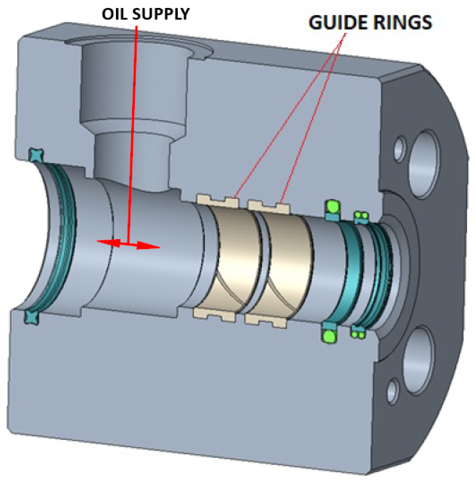
2.1. Design of the Guide with Guide Rings

The head of the hydraulic cylinder with guide rings is shown in Figure 2. The piston rod is guided by two guide rings. The two guide elements SKF F08 (Table 3) [44] were used. Each ring is 18 mm wide, so that the total width is 36 mm. The guide ring is made of polytetrafluoroethylene (PTFE) with an additional 40 % bronze content.

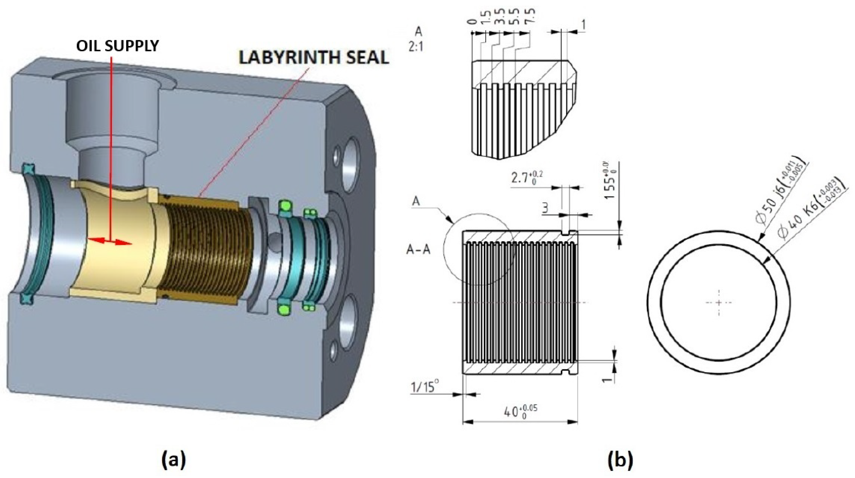
2.2. Design of the Guide with Labyrinth Seal

The hydraulic cylinder head with labyrinth seal is shown in Figure 3a. The labyrinth seal (Figure 3b) was manufactured based on the desired gap size between the piston rod and the seal. With standard components, the gap would be too large, resulting in a higher flow rate and lower pressure drop. A labyrinth seal is developed to reduce the flow rate and increase the pressure drop. A pressurized fluid increases its velocity as it flows through the slot. The pressure difference causes turbulence in the groove behind the slot, which increases the flow resistance. This process is repeated with each subsequent passage through the slot and the radial groove, resulting in a gradual drop in pressure. The labyrinth sealing effect is only achieved if all grooves can be flown through. The oil that has passed through the labyrinth seal is connected to the return or leakage line to the tank. The labyrinth seal shown and marked in Figure 3 is made of bronze Rg7. The shape, dimensions, and number of radial grooves were summarized in [45], where a computer simulation is also included.

2.3. Design of the Guide with Hydrostatic Bearing

The head of the hydraulic cylinder with hydrostatic bearing is shown in Figure 4a. Holes had to be drilled in the side of the hydraulic cylinder head (four in this study, as the bearing has four pockets) to feed pressurized fluid into the bearing. The pockets form the bearing surface. A bushing (Figure 4b) with four pockets was designed for this purpose. A bushing inserted into the head of the hydraulic cylinder forms the pockets of the bearing. Figure 4 shows the head of the hydraulic cylinder with the bushing. The calculation of the hydrostatic bearing with four pockets was carried out according to [46].

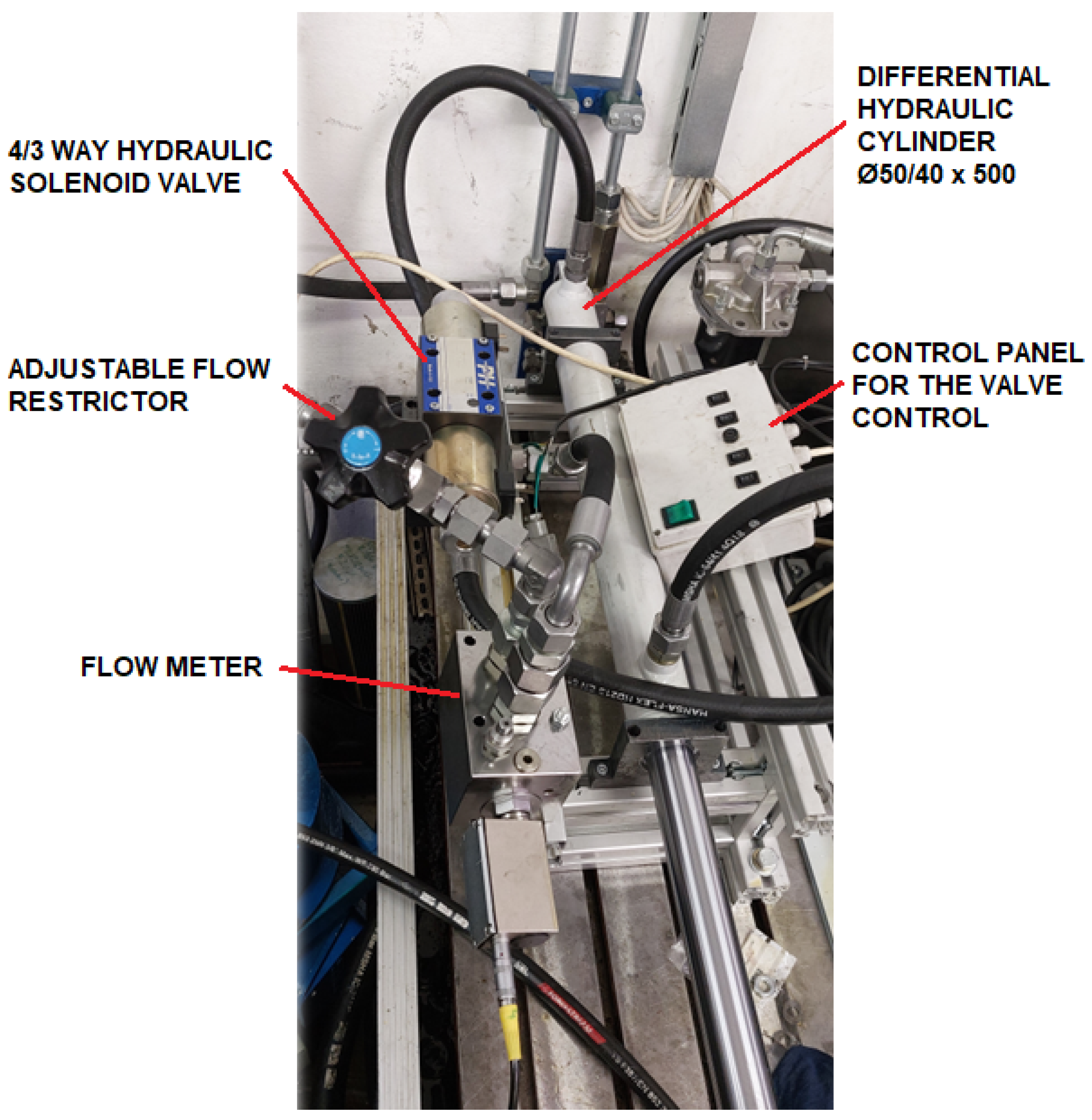
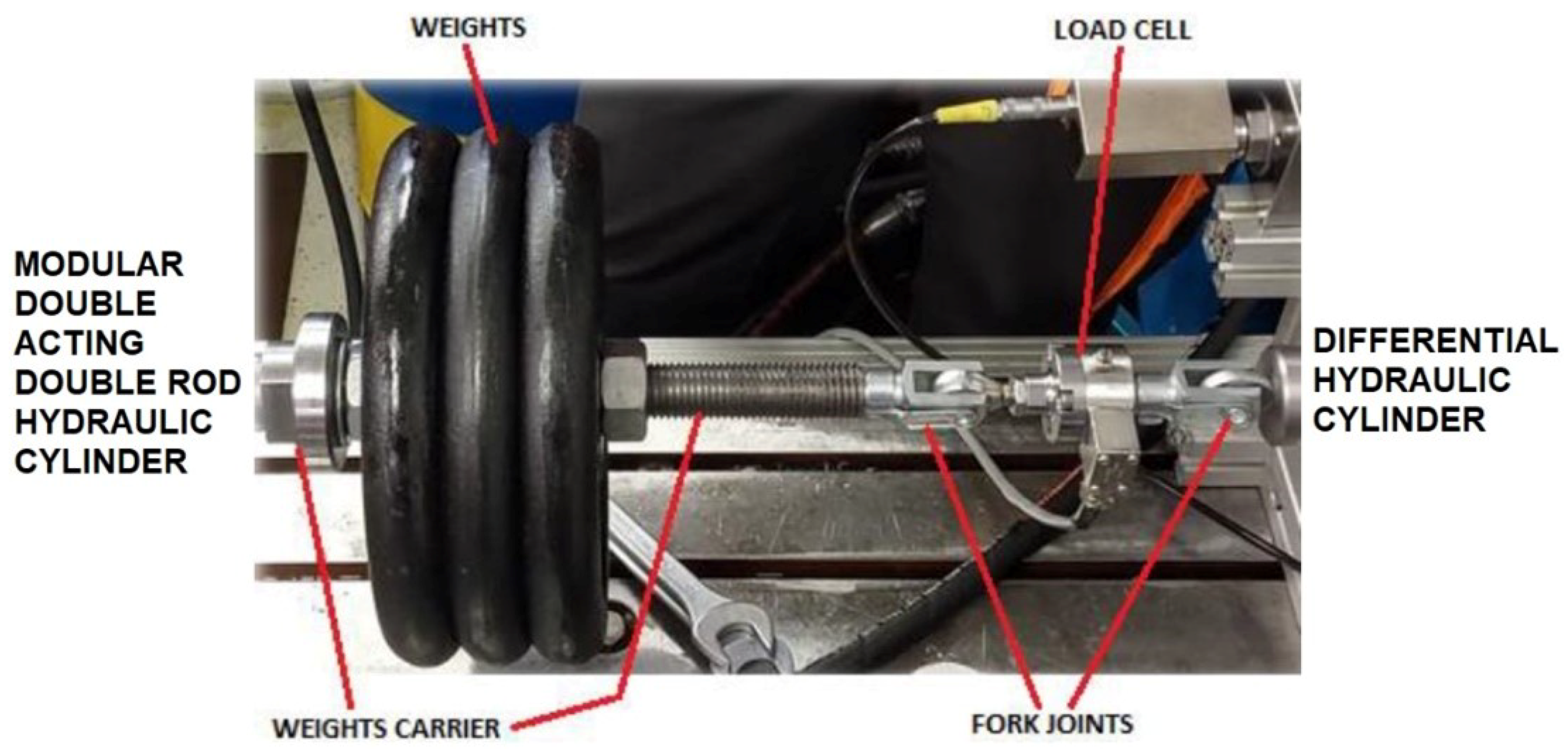
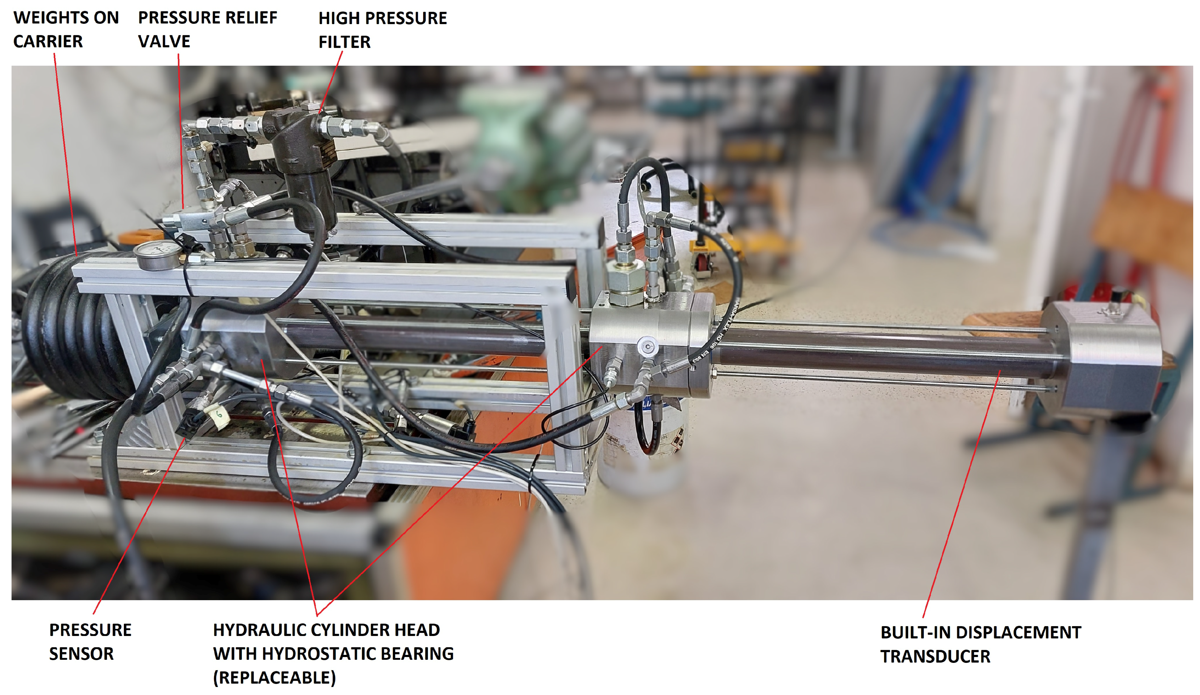
3. Experimental Setup

A test stand (Figure 5) was designed and manufactured for the measurement, with which the test parameters can be set quickly and easily. It consists of a double-acting hydraulic cylinder ϕ 50/40 × 500, with which the piston rod is extended from the modular hydraulic cylinder. The double-acting cylinder is controlled by a directional 4/3 solenoid hydraulic valve with electromagnetic actuation. The extension velocity is set indirectly with an adjustable flow restrictor and a flow meter (Parker, SCFT-300-02-02). Figure 6 shows part of a test rig with differential cylinder, flow restrictor, flow meter, and directional 4/3 solenoid hydraulic valve. The hydraulic connections are made with flexible hoses. The piston rod of the test cylinder (modular) and the piston rod of the differential cylinder are connected to a load cell via the fork joints so that the piston rod hangs freely (Figure 7). In order to simulate the radial load on the piston rod, a special beam (weights carrier) was constructed on which various masses can be suspended that generate a radial load on the piston rod. Radial forces also occur in hydraulics (due to structural deformations, dynamic loads, inappropriate alignments, etc.). The hydraulic cylinder to be tested is positioned in the axis with the differential cylinder in such a way that the piston rod (modular hydraulic cylinder) is extended by 500 mm. The displacement of the piston rod was measured using a displacement sensor integrated into the modular hydraulic cylinder (Figure 8). The modular hydraulic cylinder consists of three heads, whereby the head with integrated displacement sensor (at the bottom of the cylinder) is fixed for all three guide element types, while the heads with the different guide types are interchangeable. The hydraulic cylinder is held together by four threaded rods. During the measurement, displacement, pressure, flow, and force were measured. The number of pressures measured depended on the type of guide. For all three types of guides, the pressure was measured at the inlet of the hydraulic cylinder and between the seal of the piston rod and the guide element. In addition to the pressures already mentioned, the pressures in the individual pockets were also measured during the tests of the hydrostatic bearing. The tests were carried out at different pressures in the hydraulic cylinder and in the hydrostatic bearing. The pressures were set using an adjustable pressure relief valve. The high-pressure filter (Figure 8) was used to ensure cleanliness. The oil flowing through the guide element (leakage line) was channelled directly into the tank without any additional elements that could cause an increase in pressure. The modular design of the hydraulic cylinder is shown in Figure 8. All tests were carried out with mineral hydraulic oil (HYDROLUBRIC VG 46, OLMA) at 50 °C. The viscosity of the oil is 30 mm2/s.

3.1. The Measurement Procedure

Frictional force measurements of various guiding elements were carried out on the test bench shown on Figure 5, Figure 6, Figure 7 and Figure 8. The measurement was carried out in the direction of extension of the piston rod of the hydraulic cylinder under test or retraction of the differential hydraulic cylinder, so that the tensile force was recorded by the load cell. A mobile diagnostic test device (Parker Service Master plus—Figure 5) was used as the measurement system for recording the measured values (pressure, displacement, and force). The directional 4/3 solenoid hydraulic valve was controlled by a switch in the control panel (Figure 6). The measurements were carried out at three different pressures (guide rings at 0 bar, 120 bar, and 240 bar; labyrinth seal and hydrostatic bearing at 20 bar, 120 bar, and 240 bar), which varied depending on the type of guide. The selected pressures are representative of typical operating conditions and allow us to investigate the behaviour of frictional forces in a range of practical conditions. By including both low and high pressures, we can assess how friction increases with applied load and determine whether non-linear effects or transitions occur in the lubrication regimes. The labyrinth seal and the hydrostatic bearing require a minimum supply pressure for operation, which is why the measurements start at 20 bar and not at 0 bar. This makes it possible to have lubrication and sealing mechanisms in operation to allow a realistic assessment of the friction behaviour under operating conditions. The second parameter was the flow rate (set with an adjustable flow restrictor) or the velocity of the piston rod of the differential cylinder. The flow rate varied between 4 L/min and 60 L/min, and measurements were taken at five different flow rates (4 L/min, 15 L/min, 30 L/min, 45 L/min, and 60 L/min). The third variable parameter was the load, which simulated an external radial load on the end of the piston rod. The maximum load was 50 kg.

3.2. Hydraulic Schemes

The hydraulic scheme with the hydraulic components is shown in Figure 9. The hydraulic power unit (pos. 1) consists of a 20 kW electric motor (pos. 1.2), which drives an axial piston pump (pos. 1.1) with variable displacement (46 cm3/rev). The pump is supplied with oil from the 150 litre tank (pos. 1.7). Safety is ensured by the pressure relief valve (pos. 1.3), which is set to 300 bar. The pump is protected against hydraulic shocks by a check valve (pos. 1.4). A high-pressure filter with bypass is located downstream of the check valve (pos. 1.5). An adjustable flow restrictor (pos. 3), with which the desired flow rate can be set, is located upstream of the flow meter (pos. 4) A directional-control 4/3 solenoid valve is located in pos. 5 and a differential hydraulic cylinder in pos. 6. The return fluid is routed into the reservoir via a low-pressure filter with bypass (pos. 1.6). A smaller hydraulic power unit was used to generate pressure in the test cylinder. It consists of a 5 kW electric motor (pos. 2.2), which drives a gear pump (pos. 2.1) with a fixed displacement of 8 cm3/rev. The suction port is connected to the same tank (pos. 1.7) as the axial piston pump with variable displacement (pos. 1.1). The pressure in the cylinder of the hydraulic cylinder under test was set by the safety valve (pos. 2.3). A check valve (pos. 2.4) is installed to protect the pump from hydraulic shocks. Position 2.5 is a high-pressure filter with bypass. Position 6 is the differential hydraulic cylinder that pulls the piston rod out of the test cylinder (pos. 7). The test cylinder has a built-in displacement transducer (pos. 8). Positions 9.1–9.6 are pressure sensors, pos. 10 is an external load that simulates the radial load, and pos. 11 is a load cell. Figure 9 also schematically shows individual parts ((a), (b), in (c)), which differ depending on the guide element (three different guide elements).

4. Results

The measurements of the individual guide systems of the piston rod were measured at sixty points. The results relate only to the hydraulic cylinder under test and are independent of the differential hydraulic cylinder, which was only used to pull out the piston rod during the measurement.

4.1. Guidance with Guide Rings

The measured frictional forces for the design using guide rings are shown and reported separately for each pressure used in Figure 10, Figure 11 and Figure 12. At a pressure of 0 bar (Figure 10), the frictional force at the velocities below 0.1 m/s increases with increasing radial load (from 0 kg to 50 kg) to 540 N at 0 kg and 1390 N at 50 kg. In addition, the frictional force decreases rapidly with increasing velocity and reaches its lowest value (270 N at 30 kg) at 0.15 m/s. This decrease in frictional force is greater with higher radial loads. A further increase in velocity leads to a slight increase in the frictional force, which reaches a value of around 500 N for all radial loads used at velocities above 0.5 m/s. At a pressure of 120 bar (Figure 11), the trend of the curves is similar to that for 0 bar of pressure (see Figure 10). At velocities below 0.1 m/s, the frictional forces increase with increasing radial load, being 830 N at 0 kg and 1280 N at 50 kg. With increasing velocity, the frictional force decreases and reaches its lowest value (511 N at 30 kg) at 0.17 m/s. This decrease in frictional force is greater with higher radial loads. A further increase in velocity leads to a slight increase in frictional force at values between 600 N and 800 N for velocities above 0.4 m/s. At a pressure of 240 bar (Figure 12), the trend of the curves is similar to that for 0 bar and 120 bar of pressure (see Figure 10 and Figure 11), but the initial frictional forces are even higher than at pressures of 0 bar and 120 bar, indicating that a higher pressure increases the initial frictional forces. At velocities below 0.1 m/s, the frictional forces increase with increasing radial load, being 1040 N at 0 kg and 1800 N at 50 kg. With increasing velocity, the frictional force decreases rapidly and reaches its lowest value (690 N at 50 kg) at 0.17 m/s. This decrease in frictional force is greater with higher radial loads. A further increase in velocity leads to a slight increase in frictional force at values between 800 N and 950 N for velocities above 0.4 m/s. The graphs in Figure 10, Figure 11 and Figure 12 show that the pressure has an additional influence on the frictional force, as an increase in pressure in the cylinder also increases the frictional force, both at the beginning and with increasing velocity.

4.2. Guidance with Labyrinth Seal

The measured frictional forces for design with labyrinth seals are shown and reported separately for each pressure used in Figure 13, Figure 14 and Figure 15. At a pressure of 20 bar (Figure 13), the frictional force at the velocities below 0.1 m/s increases with increasing radial load (from 0 kg to 50 kg), being 260 N at 0 kg and 1010 N at 50 kg. Furthermore, the frictional force decreases with increasing velocity and reaches its lowest value (100 N at 0 kg) at 0.2 m/s. A further increase in velocity leads to a slight increase in the frictional force, which stabilises at values around 150 N at 0 kg and 10 kg, 320 N at 30 kg, and 700 N at 50 kg for velocities above 0.4 m/s. The curves at a radial load of 30 kg and 50 kg stand out from the curves at 0 kg and 10 kg. At a pressure of 120 bar (Figure 14), the trend of the curves is similar to that for 20 bar of pressure (see Figure 13). At velocities below 0.1 m/s, the frictional force increases with increasing radial load, being 238 N at 0 kg and 1022 N at 50 kg. Furthermore, the frictional force decreases rapidly with increasing velocity and reaches its lowest value (10 N at 10 kg) at 0.2 m/s. A further increase in velocity leads to a slight increase in the frictional force, which stabilises at values between 70 N and 110 N at 0 kg, 10 kg, and 30 kg, and 420 N at 50 kg. The curve for a radial load of 50 kg stands out from the curves for the other radial loads. At a pressure of 240 bar (Figure 15), the trend of the curves is similar to that for 20 bar and 120 bar (see Figure 13 and Figure 14). The initial values of the frictional forces increase with increasing radial load at velocities below 0.1 m/s, being 284 N at 0 kg and 902 N at 50 kg. Furthermore, the frictional force decreases rapidly with increasing velocity and reaches its lowest value (30 N at 30 kg) at 0.21 m/s. A further increase in velocity leads to a slight increase in frictional force, levelling off at values between 100 N and 300 N for velocities above 0.4 m/s. There are no significant deviations between the curves. From the graphs in Figure 13, Figure 14 and Figure 15, it can be seen that the pressure influences the frictional force above all at higher radial loads, as the differences between the curves are smallest at a pressure of 240 bar (Figure 15).

4.3. Guidance with Hydrostatic Seal

The measured frictional forces for design with hydrostatic bearing are shown and reported separately for each pressure used in Figure 16, Figure 17 and Figure 18. At a pressure of 20 bar (Figure 16), the frictional force at velocities below 0.1 m/s increases with increasing radial load (from 0 kg to 50 kg), being 736 N at 0 kg and 1760 N at 50 kg. In addition, the frictional force decreases rapidly with increasing velocity and reaches its lowest value (10 N at 50 kg) at 0.21 m/s. A further increase in velocity leads to a slight increase in frictional force, which reaches values between 100 N and 200 N at velocities above 0.5 m/s. At a pressure of 120 bar (Figure 17), the trend of the curves is similar to that for 0 bar (see Figure 16). At velocities below 0.1 m/s, the frictional force increases with increasing radial load, being 700 N at 0 kg and 1430 N at 50 kg. Furthermore, the frictional force decreases rapidly with increasing velocity and reaches its lowest value (30 N at 50 kg) at 0.23 m/s. A further increase in velocity leads to a slight increase in frictional force (approx. 50 N per 0.1 m/s). At a pressure of 240 bar (Figure 18), the trend of the curves is similar to that for 0 bar and 120 bar of pressure (see Figure 16 and Figure 17). At velocities below 0.1 m/s, the frictional force increases with increasing radial load, being 740 N at 0 kg and 1450 N at 50 kg. Furthermore, the frictional force decreases rapidly with increasing velocity and reaches its lowest value (50 N at 50 kg) at 0.21 m/s. A further increase in velocity leads to a slightly greater increase in frictional force than at 120 bar, reaching a maximum value of 530 N at 10 kg at a velocity of 0.6 m/s. The violet curve represents the measurement without orifice (flow restrictor). The initial values of the frictional force are almost the same as for the measurements with the orifice, but reach better minimum values (10 N) at 0.23 m/s. A further increase in velocity leads to an increase in the frictional force, which reaches a maximum of 580 N at 0.58 m/s. The graphs in Figure 16, Figure 17 and Figure 18 show that the pressure reduces the initial frictional forces, especially at higher radial loads. Figure 18 shows a measurement without the use of orifices (restrictors). It can be seen that the curve does not deviate significantly from the other measurements.
Figure 19 shows the measurement results of three different guide elements at a pressure of 240 bar and a radial load of 50 kg. This is the pressure that normally occurs in hydraulic systems. Such high radial loads are not desirable in hydraulic systems, but in our case the radial load of 50 kg was used to test how different components (especially guide elements) work and how robust they are. Guide rings (GRs) have the highest initial frictional force (approx. 1800 N), followed by hydrostatic bearing (HB), with approx. 1450 N frictional force; the lowest is the labyrinth seal (LS), with approx. 902 N frictional force. Furthermore, the frictional force decreases with increasing velocity. The minimum value for GR is 690 N at 0.18 m/s, 210 N at 0.23 N for LS, and 50 N at 0.21 m/s for HB. A further increase in velocity leads to an increase in frictional force. The gradient is steepest for HB, followed by GR, and is most constant for LS. The steeper the curve, the greater the increase in frictional force.

5. Discussion

In this study, an experimental analysis of three different designs of guide elements in a hydraulic cylinder was carried out: guide rings, labyrinth seals, and hydrostatic bearings. The results showed that the design, in particular the choice of guide element, has a significant influence on friction, which plays a crucial role in optimising the performance of hydraulic cylinders. In hydraulic cylinders, guide elements are the key components for ensuring proper guidance. The choice of guide element has a significant influence on the pressure distribution. With guide rings, the pressure acting on the seal is equal to the system pressure. The higher the system pressure, the more the seal presses against the piston rod of the cylinder, which further increases friction, which was also concluded in [41]. Labyrinth seals utilise the kinetic energy of the fluid flowing through them; turbulence in the radial grooves only occurs when a flow is present. This turbulence reduces the energy and therefore the flow rate. The pressure decreases as the fluid flows through the grooves and is almost equal to the ambient pressure at the outlet, so that the seal only generates as much friction as is caused by the pressure of the O-ring, which presses the seal against the piston rod. With a labyrinth seal, a leakage line must be provided to direct the fluid passing through the labyrinth seal into the reservoir. In the case of a hydrostatic bearing, proper functioning requires the supply of pressurised fluid into the pockets. The pressurised fluid forms a thin film that separates the two surfaces. Due to the leakage path in front of the seal, the seal is not exposed to pressure as with the guide rings, so that the seal generates only low friction. Each of the above-mentioned guide elements have different advantages and disadvantages [32,39,45,46,47,48,49,50,51,52,53,54,55,56,57,58].

5.1. Guidance with Guide Rings

For all pressures and radial loads (Figure 10, Figure 11 and Figure 12), all diagrams show the general trend that the frictional force decreases with increasing velocity up to about 0.2 m/s, which is due to a reduction in surface asperity contact friction between the surfaces. As the velocity increases further, the friction increases slightly, which is due to increased shear within the lubricating film. The highest friction force values occur at lower velocities and higher radial loads, indicating a greater influence of the load on the contact surface. At 240 bar, the frictional forces are higher than at the lower pressures (0 bar and 120 bar), indicating the important role of pressure in increasing friction. A higher system pressure leads to a higher pressure on the seal, which contributes to an increase in frictional force due to the increased pressure of the seal on the piston rod. In addition to the pressure, the radial load also further increases the frictional force. These results highlight the importance of controlling pressure and radial load in applications where friction can affect system performance

5.2. Guidance with Labyrinth Seal

For all pressures and radial loads (Figure 13, Figure 14 and Figure 15), the frictional force decreases with increasing velocity up to approx. 0.2 m/s. After that, friction stabilizes or increases slightly, which is due to the viscous friction within the lubricating film. The maximum friction values are reached at the highest radial loads, which indicates a greater influence of the radial load on the seal. The frictional force decreases with increasing pressure, which is due to better centring of the piston rod in the centre of the bore and therefore better lubrication.

5.3. Guidance with Hydrostatic Bearing

For all pressures and radial loads (Figure 16, Figure 17 and Figure 18), all diagrams show that the frictional force decreases rapidly with increasing velocity up to 0.2 m/s and then increases slightly with increasing velocity. The highest friction force values are observed at the highest radial loads, which indicates a greater influence of the radial load on the bearing. The friction force values are not significantly affected by the pressure, but the friction force increases faster at higher pressures (240 bar) after reaching the minimum value than at 20 bar and 120 bar (the curves have a steeper slope).
Other researchers [14] have also found that the curves (Figure 10, Figure 11, Figure 12, Figure 13, Figure 14, Figure 15, Figure 16, Figure 17 and Figure 18) have a similar shape to Stribeck’s [45] curve. The curve illustrates three different types of friction: boundary, mixed, and hydrodynamic friction. At the beginning, the surfaces are in direct contact, which leads to the highest friction (boundary friction). In the area of mixed friction, the surfaces are partially separated by the lubricant, which reduces the friction to a minimum value. When this minimum is reached, hydrodynamic friction begins, in which the surfaces are completely separated by a thin layer of lubricant and the friction is mainly caused by the viscose friction induced by shear stresses within lubricating film [32,59]. According to the classic Stribeck curve and the hydrodynamic lubrication regime, such a scenario is to be expected, but only if the following conditions are met: At the lowest speeds (and with a radial load of 50 kg), there is direct contact between the contact surfaces. In this case, the system is subject to friction at the ’solid–solid’ level, which is very high, as the lubricating film cannot separate the two contact surfaces. As the speed increases, a thicker and thicker lubricating film forms, which reduces the friction contribution at the solid level and thus also the overall friction. When the film is full, the viscous component of the friction begins to dominate and increases with speed, as a higher speed also means a higher shear stress in the lubricant, as shown in Equation ( τ = η · ( v h ) ). According to the equation, as the sliding speed increases, the shear also increases (although this makes the lubricating film thicker (h), but the increase in speed (v) is greater than the increase in thickness, h).
Figure 20 and Figure 21 show a comparison of the individual guide elements used: guide ring, labyrinth seal, and hydrostatic bearing. Figure 20 shows the minimum values of the frictional force, while Figure 21 shows the maximum values of the frictional force at different pressures and radial loads. The minimum frictional forces were achieved at velocities of around 0.2 m/s, with the maximum being reached at the minimal velocity.
The highest friction force at start-up (1800 N) was measured with the guide rings at 240 bar and a radial load of 50 kg, while the lowest (238 N) was measured with the labyrinth seal at 120 bar and no radial load. The highest average frictional force (988 N) during movement was measured with the guide rings at 240 bar with no radial load, while the lowest (17 N) was measured with the labyrinth seal at 120 bar and a radial load of 10 kg.

6. Conclusions

A modular hydraulic cylinder with displacement sensor was designed and manufactured. It allows the replacement of heads with three different design types of guide systems: guide rings, labyrinth seals, and hydrostatic bearings. Friction measurements were carried out for all three different designs of piston rod guide systems. Based on the detailed analysis and comparative study of frictional forces in hydraulic cylinders with different designs of guide elements, we can conclude that the choice of guide element plays a crucial role in optimising the performance and efficiency of hydraulic systems. This study provides important insights into the frictional behaviours of guide rings, labyrinth seals, and hydrostatic bearings at different pressures, velocities, and radial loads. Guide rings are effective and reliable but exhibit the highest frictional forces, especially under higher pressures and radial loads, which may lead to increased wear and energy consumption in long-term operations. Labyrinth seals, on the other hand, exhibit significantly lower frictional forces, making them preferable for applications where the focus is on reducing friction and extending the service life of components. The hydrostatic bearings are complex systems which needs fluid under pressure for appropriate operation. In the case of proper operation, significantly low friction forces can be achieved. Their complexity and need for precise control might limit their application to specialized cases. The results of this study not only improve the understanding of friction in hydraulic systems, but also provide practical guidelines for the selection of the most suitable designs of guide elements based on the specific operating conditions. By carefully considering these factors, engineers can achieve better performance, longer life, and higher energy efficiency in hydraulic systems. Future research should focus on investigating the long-term effects of these three different designs of guide elements in real-world applications, as well as the potential for further innovation to reduce friction and improve hydraulic cylinder performance. This comprehensive analysis provides a solid basis for improving the design of hydraulic cylinders, contributes to advances in the field of fluid power engineering, and offers valuable recommendations for industrial applications.

Author Contributions

Conceptualization, J.P., U.B. and F.M.; methodology, J.P.; software, J.P. and V.T.; validation, J.P., A.T., M.P. and U.B.; formal analysis, J.P.; investigation, J.P. and V.T.; data curation, J.P., U.B. and F.M.; writing—original draft preparation, J.P.; writing—review and editing, V.T., M.P., A.T. and F.M.; visualization, J.P. and U.B.; supervision, F.M. All authors have read and agreed to the published version of the manuscript.

Funding

This work was supported by the Slovenian Research and Innovation Agency as part of the research program no. L2-50083.

Institutional Review Board Statement

Not applicable.

Informed Consent Statement

Not applicable.

Data Availability Statement

Data available on request from the authors.

Acknowledgments

We would like to thank Miha Lazar, who took part in the measurement.

Conflicts of Interest

The authors declare no conflicts of interest.

References

  1. Pabsetti, P.; Murty, R.S.V.N.; Bhoje, J.; Mathew, S.; Harivenkatesh; Rahul, K.; Feroskhan, M. Performance of hydraulic oils and its additives in fluid power system: A review. IOP Conf. Ser. Earth Environ. Sci. 2023, 1161, 012009. [Google Scholar] [CrossRef]
  2. Majdič, F.; Pezdirnik, J.; Kalin, M. Voda Kot Kapljevina vs. Pogonsko-Krmilni Hidravliki: Doktorsko Delo. Ph.D. Thesis, Univerza v Ljubljani, Ljubljana, Slovenia, 2010. [Google Scholar]
  3. Kambic, M.; Kalb, R.; Tic, V.; Lovrec, D. Compatibility of ionic liquids with hydraulic system components. Adv. Prod. Eng. Manag. 2018, 13, 492–503. [Google Scholar] [CrossRef]
  4. Lovrec, D.; Kalb, R.; Tič, V. Application Areas of Ionic Hydraulic Fluids. Chem. Eng. Technol. 2023, 46, 14–20. [Google Scholar] [CrossRef]
  5. Manring, N.D.; Fales, R.C. Hydraulic Control Systems; Wiley: Hoboken, NJ, USA, 2019. [Google Scholar] [CrossRef]
  6. Chen, P.; Chua, P.; Lim, G. A study of hydraulic seal integrity. Mech. Syst. Signal Process. 2007, 21, 1115–1126. [Google Scholar] [CrossRef]
  7. Sotoodeh, K. Actuator selection and sizing for valves. SN Appl. Sci. 2019, 1, 1207. [Google Scholar] [CrossRef]
  8. Abuowda, K.; Okhotnikov, I.; Noroozi, S.; Godfrey, P.; Dupac, M. A review of electrohydraulic independent metering technology. ISA Trans. 2020, 98, 364–381. [Google Scholar] [CrossRef]
  9. Mattila, J.; Koivumaki, J.; Caldwell, D.G.; Semini, C. A Survey on Control of Hydraulic Robotic Manipulators with Projection to Future Trends. IEEE/ASME Trans. Mechatron. 2017, 22, 669–680. [Google Scholar] [CrossRef]
  10. Tanaka, Y.; Sakama, S.; Nakano, K.; Kosodo, H. Comparative Study on Dynamic Characteristics of Hydraulic, Pneumatic and Electric Motors. In Proceedings of the ASME/BATH 2013 Symposium on Fluid Power and Motion Control, American Society of Mechanical Engineers, Sarasota, FL, USA, 6–9 October 2013. [Google Scholar] [CrossRef]
  11. Wiens, T.; Deibert, B. A Low-Cost Miniature Electrohydrostatic Actuator System. Actuators 2020, 9, 130. [Google Scholar] [CrossRef]
  12. Sakama, S.; Tanaka, Y.; Kamimura, A. Characteristics of Hydraulic and Electric Servo Motors. Actuators 2022, 11, 11. [Google Scholar] [CrossRef]
  13. Fassbender, D.; Zakharov, V.; Minav, T. Utilization of electric prime movers in hydraulic heavy-duty-mobile-machine implement systems. Autom. Constr. 2021, 132, 103964. [Google Scholar] [CrossRef]
  14. Pan, Q.; Zeng, Y.; Li, Y.; Jiang, X.; Huang, M. Experimental investigation of friction behaviors for double-acting hydraulic actuators with different reciprocating seals. Tribol. Int. 2021, 153, 106506. [Google Scholar] [CrossRef]
  15. Kastrevc, M.; Gubeljak, N.; Detiček, E. Design and tuning of the Lyapunov based nonlinear position control of electrohydraulic servo systems. Facta Univ. Ser. Mech. Eng. 2022, 62, 163–170. [Google Scholar]
  16. Shi, H.; Gong, G.; Yang, H.; Mei, X. Compliance of hydraulic system and its applications in thrust system design of shield tunneling machine. Sci. China Technol. Sci. 2013, 56, 2124–2131. [Google Scholar] [CrossRef]
  17. Davis, S. Pneumatic Actuators. Actuators 2018, 7, 62. [Google Scholar] [CrossRef]
  18. Meng, F.; Huang, Q.; Yu, Z.; Chen, X.; Fan, X.; Zhang, W.; Ming, A. Explosive electric actuator and control for legged robots. Engineering 2022, 12, 39–47. [Google Scholar] [CrossRef]
  19. Valilou, S. Nonlinear Model and Control of Electro-Hydraulic Servo Systems. Ph.D. Thesis, University of Bergamo, Bergamo, Italy, 2017. [Google Scholar]
  20. Maltezos, E.; Papoutsidakis, M.; De Negri, V. A study of hydraulic actuator control methods in simulation. Int. J. Eng. Appl. Sci. Technol. 2019, 4, 455–462. [Google Scholar] [CrossRef]
  21. Papoutsidakis, M.; Chatzopoulos, A.; Papachristos, D.; Drosos, C. Hydraulics and Pneumatics: Operational Characteristics and Control for Modern Industry Applications. Int. J. Comput. Appl. 2019, 178, 31–40. [Google Scholar] [CrossRef]
  22. Mendoza, G.; Igartua, A.; Fernandez-Diaz, B.; Urquiola, F.; Vivanco, S.; Arguizoniz, R. Vegetable oils as hydraulic fluids for agricultural applications. Grasas Y Aceites 2011, 62, 29–38. [Google Scholar] [CrossRef]
  23. Tkáč, Z.; Čorňák, Š.; Cviklovič, V.; Kosiba, J.; Glos, J.; Jablonický, J.; Bernát, R. Research of Biodegradable Fluid Impacts on Operation of Tractor Hydraulic System. Acta Technol. Agric. 2017, 20, 42–45. [Google Scholar] [CrossRef]
  24. Jabal, M.; Abdulmunem, A.; Abd, H. As a potential hydraulic fluid: Corn oil behavior characteristics examination. J. Therm. Eng. 2021, 7, 215–221. [Google Scholar] [CrossRef]
  25. Kučera, M.; Aleš, Z.; Ivandić, Z.; Hujo, Ľ. Possibility of hydraulic fluids with a low environmental impact application in agriculture and transport machinery. J. Cent. Eur. Agric. 2013, 14, 1575–1584. [Google Scholar] [CrossRef]
  26. Tič, V.; Tašner, T.; Lovrec, D. Enhanced lubricant management to reduce costs and minimise environmental impact. Energy 2014, 77, 108–116. [Google Scholar] [CrossRef]
  27. Chiavola, O.; Frattini, E.; Palmieri, F.; Fioravanti, A.; Marani, P. On the Efficiency of Mobile Hydraulic Power Packs Operating with New and Aged Eco-Friendly Fluids. Energies 2023, 16, 5681. [Google Scholar] [CrossRef]
  28. Mozetič, M.; Majdič, F. Trenje Batnih Tesnil vs. Hidravličnem Valju in Trajnostni Preizkus; Univerza v Ljubljani: Ljubljana, Slovenia, 2022. [Google Scholar]
  29. Oblak, R.; Kramar, P. Senzorji za Zaznavanje Pozicije Batnice vs. Hidravličnem Valju; Univerza v Ljubljani: Ljubljana, Slovenia, 2016. [Google Scholar]
  30. Chen, X.; Zheng, F.; Gan, W.; Xing, S. Exploration and Research on Key Technologies for Improving the Response Speed of Servo-Hydraulic Cylinders. Appl. Sci. 2022, 12, 4162. [Google Scholar] [CrossRef]
  31. Beacham, T.E.; Towler, F.H. Hydraulic Seals. Proc. Inst. Mech. Eng. 1949, 160, 532–569. [Google Scholar] [CrossRef]
  32. Wang, Q.J.; Chung, Y.W. (Eds.) Encyclopedia of Tribology; Springer: Boston, MA, USA, 2013. [Google Scholar] [CrossRef]
  33. Nikas, G.K.; Hasegawa, T. Research on the tribology of hydraulic reciprocating seals. In Tribology Research Trends; Nova Science Publishers, Inc.: Hauppauge, NY, USA, 2008; pp. 11–56. [Google Scholar]
  34. Heipl, O.; Murrenhoff, H. Friction of hydraulic rod seals at high velocities. Tribol. Int. 2015, 85, 66–73. [Google Scholar] [CrossRef]
  35. Huang, Y.; Salant, R.F. Simulation of a hydraulic rod seal with a textured rod and starvation. Tribol. Int. 2016, 95, 306–315. [Google Scholar] [CrossRef]
  36. Zhang, Z.; Gao, D.; Guan, T.; Liang, Y.; Zhao, J.; Wang, L.; Tang, J. Experimental Study on Friction and Wear Characteristics of Hydraulic Reciprocating Rotary Seals. Lubricants 2023, 11, 385. [Google Scholar] [CrossRef]
  37. Belforte, G.; Bertetto, A.M.; Mazza, L. Test rig for friction force measurements in pneumatic components and seals. Proc. Inst. Mech. Eng. Part J J. Eng. Tribol. 2013, 227, 43–59. [Google Scholar] [CrossRef]
  38. Belforte, G.; Conte, M.; Manuello Bertetto, A.; Mazza, L.; Raparelli, T.; Visconte, C. Indirect contact pressure evaluation on pneumatic rod seals. Tribol. Int. 2018, 118, 240–245. [Google Scholar] [CrossRef]
  39. Reichert, M. Development of High-Response Piezo-Servovalves for Improved Performance of Electrohydraulic Cylinder Drives. Ph.D. Thesis, Fakultät für Maschinenwesen, Aachen, Germany, 2010. [Google Scholar]
  40. Azzi, A.; Maoui, A.; Fatu, A.; Fily, S.; Souchet, D. Experimental study of friction in pneumatic seals. Tribol. Int. 2019, 135, 432–443. [Google Scholar] [CrossRef]
  41. Mazza, L.; Belforte, G. Analytical/Experimental Study of the Contribution of Individual Seals to Friction Force in Pneumatic Actuators. J. Tribol. 2017, 139. [Google Scholar] [CrossRef]
  42. Ambu, R.; Bertetto, A.M.; Mazza, L. Re-design of a guide bearing for pneumatic actuators and life tests comparison. Tribol. Int. 2016, 96, 317–325. [Google Scholar] [CrossRef]
  43. Manuello Bertetto, A.; Mazza, L.; Orrù, P. Contact Pressure Distribution in Guide Bearings for Pneumatic Actuators. Exp. Tech. 2015, 39, 46–54. [Google Scholar] [CrossRef]
  44. SKF Group. Machined Seals Product Range; SKF Group: 2019. Available online: https://cdn.skfmediahub.skf.com/api/public/0901d196809ce435/pdf_preview_medium/0901d196809ce435_pdf_preview_medium.pdf (accessed on 8 April 2025).
  45. Lee, Y.B.; Park, J.W.; Lee, G.C. A Study on Failure Analysis and High Performance of Hydraulic Servo Actuator. Appl. Sci. 2020, 10, 7451. [Google Scholar] [CrossRef]
  46. Brian, W.B. Hydrostatic, Aerostatic and Hybrid Bearing Design; Elsevier: Amsterdam, The Netherlands, 2012. [Google Scholar] [CrossRef]
  47. San Andrés, L.; Wu, T.; Barajas-Rivera, J.; Zhang, J.; Kawashita, R. Leakage and Cavity Pressures in an Interlocking Labyrinth Gas Seal: Measurements vs. Predictions. In Proceedings of the ASME Turbo Expo 2019: Turbomachinery Technical Conference and Exposition, Phoenix, AZ, USA, 17–21 June 2019. [Google Scholar] [CrossRef]
  48. Li, D.; Li, Y.; Li, Z.; Wang, Y. Theory analyses and applications of magnetic fluids in sealing. Friction 2023, 11, 1771–1793. [Google Scholar] [CrossRef]
  49. Zardin, B.; Natali, E.; Cillo, G.; Borghi, M. Modelling of hydrostatic bearings for servo-cylinders. In AIP Conference Proceedings; AIP Publishing: Melville, NY, USA, 2019; p. 020156. [Google Scholar] [CrossRef]
  50. Patil, S.; Khairnar, A.; Phalle, V.M.; Limaye, P.K. Design of Self-Compensating Hydrostatic Bearing for Actuators. SSRN Electron. J. 2018, 1–6. [Google Scholar] [CrossRef]
  51. Metlikovič, P.; Emri, I. Naprava za merjenje lezenja torzijsko obremenjenih polimernih preizkušancev. Stroj. Vestn.-J. Mech. Eng. 1990, 26, 101–104. [Google Scholar]
  52. Liu, Z.; Wang, Y.; Cai, L.; Zhao, Y.; Cheng, Q.; Dong, X. A review of hydrostatic bearing system: Researches and applications. Adv. Mech. Eng. 2017, 9, 168781401773053. [Google Scholar] [CrossRef]
  53. Cheng, M. Leakage Flow of Labyrinth Seals in Hydraulic Components. In Proceedings of the ASME 2004 Heat Transfer/Fluids Engineering Summer Conference, Charlotte, NC, USA, 11–15 July 2004; pp. 1–8. [Google Scholar] [CrossRef]
  54. Trček, Č.; Majdič, F. Vpliv Radalnih Utorov na Pretoke Skozi Kolobarjaste Reže v Hidravliki; Univerza v Ljubljani: Ljubljana, Slovenia, 2014. [Google Scholar]
  55. Nabae, H.; Hemmi, M.; Hirota, Y.; Ide, T.; Suzumori, K.; Endo, G. Super-low friction and lightweight hydraulic cylinder using multi-directional forging magnesium alloy and its application to robotic leg. Adv. Robot. 2018, 32, 524–534. [Google Scholar] [CrossRef]
  56. Li, W.; Wang, X.; Zhang, X.; Zhang, X.; Zhu, Y.; Chen, H. Experimental and Numerical Investigations of Closed Radial Inflow Turbine with Labyrinth Seals. J. Eng. Gas Turbines Power 2018, 140, 102502. [Google Scholar] [CrossRef]
  57. GmbH, K.K. Non-Contact Labyrinth Seals Protect Rotating Equipment. Adhes. ADHESIVES+ SEALANTS 2021, 18, 24–25. [Google Scholar]
  58. Sheng, N.; Ruggiero, E.J.; Devi, R.; Guo, J.; Cirri, M. Experimental and Analytical Leakage Characterization of Annular Gas Seals: Honeycomb, Labyrinth and Pocket Damper Seals. In Proceedings of the VASME 2011 Turbo Expo: Turbine Technical Conference and Exposition, Vancouver, BC, Canada, 6–10 June 2011; pp. 723–729. [Google Scholar] [CrossRef]
  59. Robinson, J.W.; Zhou, Y.; Bhattacharya, P.; Erck, R.; Qu, J.; Bays, J.T.; Cosimbescu, L. Probing the molecular design of hyper-branched aryl polyesters towards lubricant applications. Sci. Rep. 2016, 6, 18624. [Google Scholar] [CrossRef] [PubMed]
Figure 1. Pressure distribution with three different guide systems on the hydraulic cylinder.
Applsci 15 04738 g001
Figure 2. Hydraulic cylinder head in cross-section with two guide rings F08 ( ϕ 170 mm × 158 mm).
Applsci 15 04738 g002
Figure 3. (a) Hydraulic cylinder head in cross-section with labyrinth seal ( ϕ 170 mm × 158 mm) and (b) base dimensions of labyrinth seal bush.
Applsci 15 04738 g003
Figure 4. (a) Hydraulic cylinder head in cross-section with hydrostatic bearing (a) hydraulic cylinder head in cross-section with hydrostatic bearing ( ϕ 170 mm × 158 mm) and (b) base dimensions of hydrostatic bearing bush.
Applsci 15 04738 g004
Figure 5. Test stand for the measurement, differential hydraulic cylinder on the left site, and cylinder under test on the right site.
Applsci 15 04738 g005
Figure 6. Part of the test site with differential hydraulic cylinder.
Applsci 15 04738 g006
Figure 7. Connection between differential and test cylinder with load cell.
Applsci 15 04738 g007
Figure 8. Modular double-acting double-rod hydraulic test cylinder.
Applsci 15 04738 g008
Figure 9. (a) Hydraulic scheme for experiments with guide rings, (b) hydraulic scheme for experiments with labyrinth seal, and (c) hydraulic scheme for experiments with hydrostatic bearing.
Applsci 15 04738 g009
Figure 10. Measured friction force in relation to velocity at a pressure of 0 bar, for the design using guide rings.
Applsci 15 04738 g010
Figure 11. Measured friction force in relation to velocity at a pressure of 120 bar, for the design using guide rings.
Applsci 15 04738 g011
Figure 12. Measured friction force in relation to velocity at a pressure of 240 bar, for the design using guide rings.
Applsci 15 04738 g012
Figure 13. Measured friction force in relation to velocity at a pressure of 20 bar, for design with labyrinth seals.
Applsci 15 04738 g013
Figure 14. Measured friction force in relation to velocity at a pressure of 120 bar, for design with labyrinth seals.
Applsci 15 04738 g014
Figure 15. Measured friction force in relation to velocity at a pressure of 240 bar, for design with labyrinth seals.
Applsci 15 04738 g015
Figure 16. Measured friction force in relation to velocity at a pressure of 20 bar, for design with hydrostatic bearing.
Applsci 15 04738 g016
Figure 17. Measured friction force in relation to velocity at a pressure of 120 bar, for design with hydrostatic bearing.
Applsci 15 04738 g017
Figure 18. Measured friction force in relation to velocity at a pressure of 240 bar, for design with hydrostatic bearing.
Applsci 15 04738 g018
Figure 19. Measured friction force in relation to velocity at a pressure of 240 bar and radial load 50 kg, guide ring (GR), labyrinth seal (LS), and hydrostatic bearing (HB).
Applsci 15 04738 g019
Figure 20. Minimal friction force values of each guide element used: guide ring, labyrinth seal, and hydrostatic bearing at different pressures and radial loads.
Applsci 15 04738 g020
Figure 21. Maximal friction force values of each guide element used: guide ring, labyrinth seal, and hydrostatic bearing at different pressures and radial loads.
Applsci 15 04738 g021
Table 1. Basic features and cross-section of piston rod wipers used in the individual hydraulic cylinder heads [44].
TypeA26-F
Dimensions (d × D × L) [mm]40 × 48.8 × 6.3
Sealing material/EnergizerX-ECOPUR/NBR70
Temperature [°C]−30 to +100
Velocity max [m/s]5
Table 2. Basic features and cross-section of piston rod seals used in the individual hydraulic cylinder heads [44].
TypeS09-D
Dimensions (d × D × L) [mm]40 × 55.1 × 6.3
Sealing material/EnergizerX-ECOPUR/NBR70
Temperature [°C]−30 to +100
Velocity max [m/s]5
Table 3. Basic features and cross-section of the piston rod guide ring used in the hydraulic cylinder heads for measurement [44].
TypeF08
Dimensions (D × d/d1 × L/L1)40 × 48/44 × 18/6 mm
Guide ring materialPTFE with 40% bronze
Temperature−200 °C to +200 °C
Velocity max5 m/s
Disclaimer/Publisher’s Note: The statements, opinions and data contained in all publications are solely those of the individual author(s) and contributor(s) and not of MDPI and/or the editor(s). MDPI and/or the editor(s) disclaim responsibility for any injury to people or property resulting from any ideas, methods, instructions or products referred to in the content.

