Abstract
The use of Hierarchical Systems (HS) technology in the conceptual design of the RWC (Robotic Work Cell) is proposed in the work. In comparison with other widespread approaches, the conceptual model of the RWC constructed in the HS formal basis contains connected models of RWC subsystems, their processes, the RWC structure, its dynamic presentation as the unit in its environment, and the RWC coordinator. The design and control system of RWC is presented in the form of an HS coordinator. For the detailed design of the selected RWC, the Visual Components system was applied in the work. First, the conceptual model of the RWC is presented in the paper. The application of the Visual Components program system for the detailed design of the RWC is described after that. Third, the laboratory experiment with the KUKA KR16-2 F robot is briefly considered. The originality of the proposed work lies in the application of the novel HS technology in the creation of the conceptual model and design of the selected RWC. The model developed at the conceptual design phase is coordinated with the model created at the detailed design phase within the framework of the Visual Components system. The effectiveness of the proposed HS approach in comparison with other known design, AI, and mathematical methods lies in the possibility of solving RWC synthesis and analysis design problems within the framework of one common formal HS model using an HS coordinator that connects the structure of the system being designed with its function, predicting, in this way, the system’s dynamics in its environment, and performing RWC control. The reliability of the model proposed was verified while performing the design and control tasks of the presented RWC and various other mechatronic objects. The results and conclusive remarks are finally presented in the paper.
1. Introduction
Modern production plants strive to automate their production so that they are more and more efficient and effective, and, at the same time, more precise and reduce costs. The process of selecting a design solution is based on a comprehensive approach, taking into account technical aspects, as well as ergonomics. When designing a robot work cell (RWC), it is necessary to plan the selection of components that will best meet production requirements and to plan the production path, which will be ergonomic, not only in terms of process efficiency but also in terms of ease of access to work areas, interface operation, and safety of people staying near the cell. It is also worth paying attention to the integration of the work cell with the entire production system, which means compatibility of production line elements with systems such as material transport or product storage. The use of the simulation software for manufacturing, e.g., the Visual Components [1] environment, supports the development of design models and simulations, which supports engineers in making decisions related to projects. Simulation software application is usually performed at the RWC detailed design phase. Conceptual models of RWC being designed are developed at the conceptual design phase of the RWC life cycle.
Currently, there are many conceptual design (CD) methods that are applied in the CD stage of Robotic Work Cells. The knowledge-based engineering (KBE) method [2,3] is among them. The design process and design models are the basic structures for extended KBE implementation. The object-oriented approach accelerates the process of source code generation of design models from the extended KBE application approach, which is also utilized in [4] to maintain multi-domain design optimization.
The other conceptual design approach, in which a decision support technique is quite developed, is model-driven engineering (MDE) [5,6]. MDE features prototype software that makes it possible to specify functional requirements for the object being designed. Here, hierarchical graphs serve as a means of knowledge representation.
The functional modeling approach presented in [7,8] was applied for knowledge representation in conceptual design. The Function-Behavior-Structure (FBS) method for conceptual design in various domains using reasoning technology for knowledge representation is described in [9,10]. Design technologies based on abstract modeling—Design Flow for Reconfigurable Architectures (INDRA)—were created to construct specific dynamic reconfigurable system architecture. These design methods are presented in [11,12,13].
In the given work, the RWC conceptual model is built on the formal basis of the Hierarchical Systems (HS) presented in [14,15,16,17]. The HS approach allows for presenting related descriptions of the structure of the designed system, its dynamic model, external environment, and coordinator within the framework of a common formal basis. This allows us to complete the design task effectively. Practical examples of how the proposed HS method can be applied in real industrial scenarios are described in [14] for the case of design and control of an MCM cutting machine, Promotech, Bialystok, Poland n a technological environment and electronic circuit board (PCB) design and testing. The recent industrial applications of the hierarchical systems method and corresponding simulations of grinding and welding processes are described in [18] and [19], respectively.
At the detailed design phase, numerous systems and virtual environments are used to create a digital model of the RWC being designed. Among the systems for design and robotic technological processes simulation is RobotStudio [20]. The system offered by ABB is a comprehensive tool for programming, simulating, and optimizing industrial robots. It allows for visualization of the working environment, programming of movements, and testing and analysis of system efficiency.
CoppeliaSim (formerly V-REP—Virtual Robot Experimentation Platform) enables the simulation of robots and other objects in a three-dimensional environment. CoppeliaSim is also used for rapid algorithm development, rapid prototyping, and simulation of production automation. It has a wide range of features, including support for different types of robots, collision detection, and physics simulation [21].
DELMIA (Dassault Systems) [22] is a software that allows for the simulation of a virtual production environment and its processes. The functionality of this program is based on advanced modeling and simulation of complex production cycles in real time. This tool allows for the optimization of production lines and enables detailed design of process stages, displaying simulations in three-dimensional space. The software offers local solutions, as well as a cloud [22].
The RoboDK system [23] enables the simulation, programming, and optimization of industrial robots’ processes. Programming is done offline, i.e., without a real robot controller, which allows designing the production process away from the workstation. The software allows simulation of many processes such as: turning, milling, welding, palletizing, packaging, and labeling. It has a library of ready-made robot models, which facilitates the process of creating simulations. The library consists of about 800 robots from 50 different manufacturers. The manufacturer ensures that advanced programming skills are not required to be able to use the program freely [23].
In this work, we focused on the Visual Components system [1] to perform RWC design at the detailed design phase of the RWC life cycle. Visual Components has similar characteristic fitches of the above-mentioned simulation systems and stands out with its clear and intuitive interface.
2. Materials and Methods
2.1. Conceptual Model Creation
Conceptual model of the Robotic Work Cell (RWC) given in theoretical basis of hierarchical systems is presented below. As mentioned above, the conceptual model of the RWC is created at the conceptual design (CD) stage before the detailed design (DD) stage of the RWC life cycle, where digital model of RWC is developed.
2.1.1. Robotic Work Cell Conceptual Model
In this work, we focused on industrial RWC. RWC contains a robot system, RWC computer trajectory planning and control system, CNC machines, belt feeders, doors, and barriers, industrial cameras, and human-operator. Conceptual model of the RWC is presented in the Hierarchical Systems (HS) formal basis [14,15,16,17] in the next form:
where is a dynamic model of RWC, is a RWC structure, is RWC coordinator, i.e., design and control system, and is index of level. Dynamic models of elements presented in form:
where is state, is input, is output, is time of level , and and are reactions and state transition functions, respectively. Conceptual models of RWC, its processes and environment are presented in the same (2) form. These models are connected by their states , inputs , and outputs [14,15,16,17].
The model of the RWC system structure is described as follows:
and includes RWC elements set and structural interactions . Therefore, in accordance with model (3), the RWC elements are:
- : robot system (RS);
- : control system (CS);
- : CNC machines (CM);
- : surveillance cameras (SC);
- : belt feeders (BF).
Furthermore, each RWC system of level − 1 has its own elements, i.e., subsystems of − 2 level. As for the KUKA robot system its subsystems are manipulator , servo-drives , ending effector and robot control unit . RWC control system (CS) connects robot control units, the RWC itself, CNC machines, belt feeders, and automatic doors, and contains program modules for subsystems integration.
Control system (CS) is the element of the RWC coordinator system. The RWC elements are interconnected by their structural connections . For instance, the ending effector and KUKA manipulator are connected by the ending link of the KUKA manipulator kinematic chain. Similarly, the higher-level subsystems are tiered by their common elements, i.e., structural interconnections that are the parts of lower levels. CNC machine and KUKA robot are tied by their mutual part—communication program unit = = of the Control System—where is a dynamic presentation of the control program that is the element of the KUKA robot , and is a dynamic model of the control program that is the element of the CNC machine .
Aggregated dynamic realizations , i.e., models of RWC elements are constructed after defining their inputs and outputs. As for CNC machine , regarding its process of instrument trajectory generation, inputs are electronic impulses which set the values of the instrument displacements, and outputs are the instrument trajectory coordinates. is the state of the trajectory fulfilment process.
Dynamic representation of RWC and its subsystems presented in form at the conceptual design (CD) stage may be converted at the detailed design (DD) stage to the following state space equation:
In (4), the first equation matches the function of states transition in , and the output equation matches the reaction . For the case of CNC machine instrument movement, the elements of states vector x = [x1 x2]T are the position x1 and speed x2. In the case of the KUKA robot movement, the conceptual model can be transformed at the DD stage to equation [24] of inverse dynamics:
Equation (5) ties vector torque T(t) as the output with vector of KUKA joints positions Q(t) as the input , where D is inertia matrix, h is vector of Coriolis and centrifugal force, c is gravity forces vector, (t) is vector of angular velocities, and is vector of angular acceleration.
The RWC environment has its own structure and integrates other technological subsystems that are in interaction with RWC and coordinator . All the subsystems are described at the conceptual design stage in (2) form.
Coordinator is described according to (1), and has its own aggregated dynamic and structure models. Coordinator is implemented in the form of the design and control system of the RWC. control functions are briefly described below in Section 2.1.2.
The metrical parameters of the RWC subsystems being designed, the parameters of RWC structure , i.e., connection defect and constructive dimension as well as RWC geometrical characteristics, are defined within an HS formal basis in the form of numerical system Ls [14], which aids useful information processing on the computer by performing operations with the appropriate numerical codes. The RWC conceptual model presented in this section gives the formal means for the Robotic Work Cell (RWC) conceptual design.
2.1.2. RWC Coordinator Control Processes
Control processes of RWC coordinator are executed by the human-computer subsystem, i.e., the man-operator with CS system. The coordination processes are:
- (1)
- robot control ;
- (2)
- RWC control processes integration ;
- (3)
- CNC machines control ;
- (4)
- surveillance cameras and belt feeders control .
Control processes are formally presented as coordinator functions in form (2) or canonical form (φ,λ) [14,15,16,17] after defining the states , inputs and outputs of RWC controlling elements. In accordance with the diagram in Figure 1, the inputs and outputs of the RWC coordinator 1, i.e., the KR C4 controller, are described on the sets of coordination and feedback signals as follows:
where is the coordination signal to the subsystems, is the feedback signal from , is the feedback signal from manipulator to the coordinator 1 of level, are signals from coordinator 1 i.e., KR C4 controller, to manipulator [14,15,16,17].
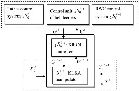
Figure 1.
RWC coordinator subsystems in control process of the KUKA robot.
In the RWC control task (Figure 1), the inputs are coordination signals which are coordinates of ending effector trajectory [x(t), y(t), z(t)] and feedback from encoders that transmit the values of the actual positions of KUKA robot joints. Outputs are electronic impulses , which set the angular value of KUKA manipulator i joint (next position), i.e., i = 6, and is the feedback signal to CNC, belt feeders BF, and CC control systems that carry information about the state. The state is the current position of KUKA manipulator joints and ending effector at t moment of time. The state of the RWC coordinating system is the input of the control process at the actual moment of time t.
As for the robotic task coordinated by robot KR C4 controller 1, the input of the KUKA robot (Figure 1) is loads of manipulator drives (servo drives). The output is the KUKA ending effector actual position, which is the input of environment element , i.e., ending the effector path in the RWC technological environment.
Coordinators (control units) of RWC sub-systems, i.e., CNC, CC, BF systems, and KUKA robots, presented in Figure 1, create a common RWC coordinator .
2.2. Development of a Digital Model of a Robotic Work Cell
The development of a digital model of a robotic work cell is described in this section. Digital model creation is performed at the detailed design phase, which follows the conceptual design phase where the conceptual model described above (see Section 2.1.1) is created. To develop the final work cell construction needed for the selected technological processes realization, several work cell prototypes were created first within the framework of the Visual Components program system environment.
2.2.1. Creation of the RWC Prototypes
Detailed design began with the creation of RWC prototypes. When creating prototypes of the work cell, the focus was on optimizing performance, precision, safety, and integration with other technological systems to ensure maximum functionality and effectiveness of the robotic work cell in real industrial conditions.
The first prototype designed is presented in Figure 2. The first version is not perfect but gives a glimpse of the future outline of the final work cell version. The main idea was to design a cell that would not be in a linear layout. The designed structure of the work cell is such that the side from which the product is fed is the same side from which the processed product comes out. Another design assumption was to create a production process consisting of two subprocesses, and , performed by four CNC machines (two for each process) due to the relatively long time of an element processing in a CNC lathe. The introduction of more CNC machines is intended to prevent longer robot downtimes while CNC machines run. The Feeler FTC-350 CNC lathe was selected for the first technological subprocess performance by the first work cell prototype proposed. For the second technological subprocess a ProLathe CNC lathe, supplied with Visual Components (VC) software [1] and available in a digital version only, was temporarily selected. As for the robot, a virtual robot from the VC library was chosen for preliminary simulation purposes.
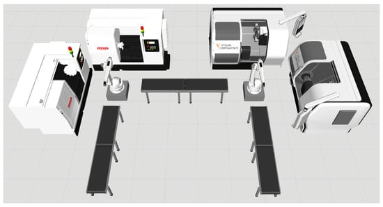
Figure 2.
The first work cell prototype.
In the last prototype (Figure 3), the arrangement of elements in the workcell was changed to solve the problem of waste collection. In this solution, the TongTai CNC machines [25] were placed so that after the insertion of protective barriers, the trolleys were on the outside of the work cell. Another improvement is the replacement of the Visual Components virtual robots with KUKA KR 16-2 F robots, which are similar in type and size. The KUKA control box selected is KR C4.
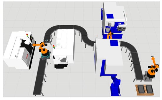
Figure 3.
The last work cell prototype.
2.2.2. Resultant Work Cell Design
The resultant cell design is shown in Figure 4. It differs from the last prototype in terms of construction. The main change is the last process improvement, i.e., packing the products into a box on a separate conveyor belt. In addition, the complete work cell includes safety measures such as barriers with doors, motion sensors, and cameras. In the final design, a solution to the prototype no. 4 problem is presented, i.e., both CNC lathe carts are placed outside the work cell. The cell has the following overall dimensions: 12 m long, 8.2 m wide, and 3.2 m high. The dimensions of the cell indicate that this could be more compact, but this solution provides additional space between the components, which makes it more convenient to perform any service inside, and the control of the cell is more transparent.
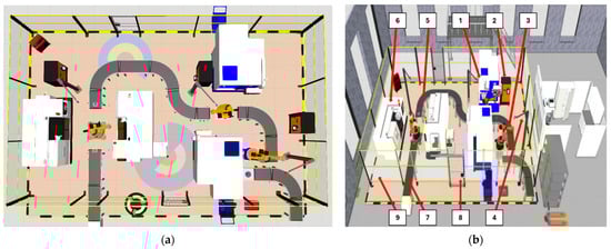
Figure 4.
Resultant work cell design, (a) is a top view, (b) is a side view.
Figure 4 shows the RWC structure and its elements described above in Section 2.1.1:
- 1 TongTai TVL-40 CNC lathe, two machines used.
- KR C4 controller (3 units used) and RWC control systems.
- Robot KUKA KR16-2 F, three robots used.
- Surveillance cameras, three units used.
- Curved belt feeders, five feeders used.
- 2 CNC lathe Feeler FTC-350, two machines used.
- Straight belt feeders, nine feeders used.
- Automatically locking doors, two doors installed.
- Barriers around work cell.
2.2.3. Work Cell Components Selection
The designed digital model consists of several basic elements , described at the conceptual design phase by dynamic system (2) (Section 2.1.1). The first one is the KUKA KR16-2 F robot (Figure 5a) with a three-point gripper. KR16-2 F is a relatively precise and versatile low-load robot. The robot has a reach of 1610 mm and a load capacity of 16 kg, and weighs 235 kg and has 6 axes. Repeatability is around ±0.05 mm [26]. This robot was chosen due to the technological task requirement formulated together with co-authors of the University of Sao Paulo, Brazil, and industrial companies’ partners. The developed model of the work cell in the Visual Components environment will allow for remote control of this robot on the principle of a “digital twin”.
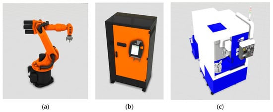
Figure 5.
(a) Robot KUKA KR16-2 F; (b) KR C4 controller; (c) TongTai TVL-40 lathe.
The second element cooperating with the KUKA robot is its KUKA KR C4 controller (Figure 5b). It allows programming (using KRL language), control, and monitoring of robot movement in various industrial applications. The controller is multifunctional and able to communicate with other elements of the work cell, such as input/output devices and production monitoring systems or sensors. The third element 1 of the work cell performing the product machining process is the TongTai TVL-40 vertical lathe (Figure 5c). It is a CNC machine designed for the precise turning of various materials in the production process. Designed with efficiency, accuracy, and versatility in mind, this lathe offers advanced functions that enable complex machining operations. The weight of the lathe is 8 tons [25].
Among other RWC elements selected are 2 CNC lathes Feeler FTC-350, surveillance cameras, belt feeders, automatically locking doors, and barriers.
2.2.4. Implementation of the RWC Components Connections
Connections among components of the RWC structure described at the conceptual design phase in the form (3) (see Section 2.1.1) are implemented at the detailed design phase as follows. The basic way of connecting components is mechanical connections. When creating an RWC and connecting two elements, such as two belt feeders (Figure 6a), the program connects them magnetically and sets them in an ideal position. Additionally, connecting components one by one, each subsequent component takes over the parameters and functionality of the previous one. This type of magnetic connection also occurs when connecting the gripper with KUKA robot. Here, the inputs and outputs of robot and gripper are connected automatically (Figure 6b).
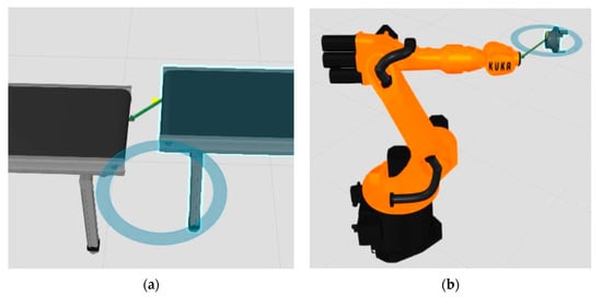
Figure 6.
Mechanical connections between (a) two feeders; (b) KUKA robot and the gripper.
Functional components of the RWC, such as robots, CNC machines, sensors, or belt feeders can also be connected using inputs and outputs by selecting them in the program “Signals” tab. This is shown in Figure 7, where inputs and outputs are connected using lines, which can be later defined and used in programming. In this method, the robot plays the main role, because each of the functions of the components, such as opening the door or starting the lathe process, is connected to the robot, which receives information in the Input positions and can control these functions in the Output positions. A slight inconvenience when creating connections is that it is not possible to arrange the lines connecting the inputs and outputs in such a way that the view is as clear as possible.

Figure 7.
RWC components connections.
RWC components and their connections work is based on electrical connections, i.e., inputs and outputs . For example, by selecting a robot and placing a belt feeder next to it, we can connect robot output 1 with a function in the feeder called “PowerOnSignal”. To activate the connection, the output state is set to 1 using the command “Set OUT [1] == True” in the robot program. This means that the feeder will be turned on. At this point, when the simulation is turned on and there is a machine part on the feeder, it will be transported in a predefined direction. Next, to stop the machine part before the end of the conveyor belt, it is necessary to install a photoelectric sensor and connect the “SensorBooleanSignal” function to the robot input 1.
In the program, the command “Wait IN [1] == True” is inserted, which means waiting for a signal, and then another command “Set OUT [1] == False” is inserted, which turns off the feeder. At this point, when switching on the simulation, the product transported by the feeder is stopped at the height of the sensor. In this way, one of the basic operations in the robot’s work cell is created and operated.
2.2.5. Processes Performed by RWC
The work cell performs three main processes , described at the conceptual design phase by dynamic system (2) (Section 2.1.1). The first process concerns the Feeler lathe (Figure 8), which performs turning in a horizontal orientation. The robot picks up the product from the belt feeder and places it in the lathe jaws, then returns to the home position. At this point, the door automatically closes, and the turning process begins. The Visual Components program does not focus on the detailed machining of a given element, so it should be treated as a simplified visualization of the process. We can see that the lathe spindle is rotating and the lathe tools are performing operations, but we will not see the machining itself on the product. The process time can be set in the lathe settings. Since Visual Components is not a program dedicated to visualizing the machining of the element itself, this process has a default time of 60 s.
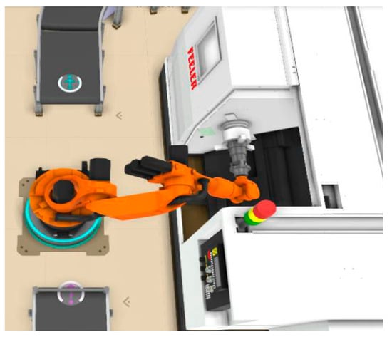
Figure 8.
Feeler lathe process.
The second process is performed using the TongTai lathe (Figure 9), which performs vertical machining. In this case, the situation with the performed process is identical to the previous Feeler lathe one, with the difference that the machining is performed in a vertical orientation.
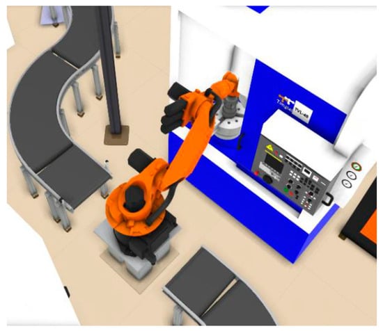
Figure 9.
TongTai lathe process.
The last process that takes place in the work cell is palletizing (Figure 10), i.e., stacking finished products, in this case, into a box. The robot receives the product from one feeder and stacks it in a box on the second feeder. Stacking always starts from a defined “Base” point in one of the corners of the box; with each subsequent product, the point moves in a row by a given distance. When the number of four elements in a row is reached, the stacking points are redefined for the next row. The process continues until the third row is complete; then, the box moves out of the work cell.
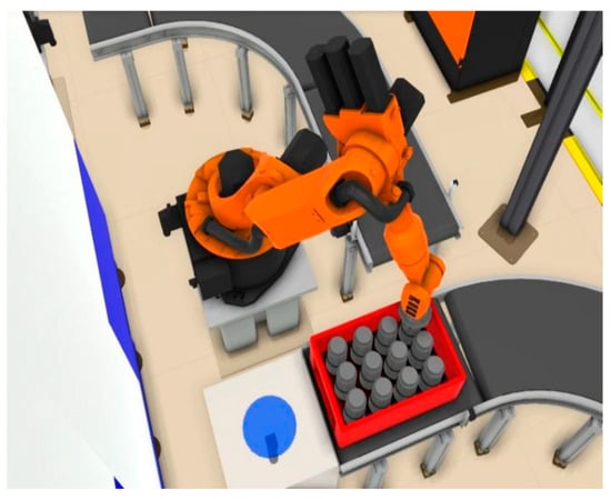
Figure 10.
Placing finished products in a box.
2.2.6. KUKA Robot Motion Control in a Laboratory Environment
The laboratory experiment was performed in a USP laboratory environment with a real KUKA KR16-2 robot (Figure 11) using a digital model of the KR16-2 robot created within the framework of the Visual Components environment. The KR16-2 robot motion control program was also developed in Visual Components software. It was saved in a .SRC and .DAT files, which are the standard format for KUKA robot programs. Then, to verify its correct operation, the program was imported into the KUKA.Sim environment (https://www.kuka.com/en-de/products/robot-systems/software/planning-project-engineering-service-safety/kuka_sim (accessed on 20 April 2025)), where the robot’s motion was simulated and analyzed.
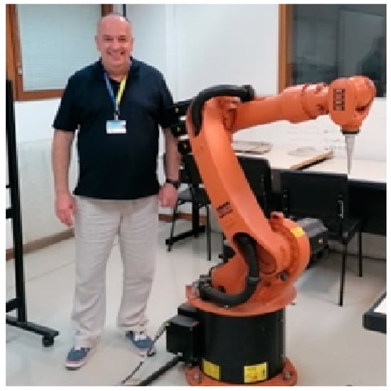
Figure 11.
Laboratory experiment at USP.
After positive verification in the KUKA.Sim software (https://www.kuka.com/en-de/products/robot-systems/software/planning-project-engineering-service-safety/kuka_sim (accessed on 20 April 2025)), the program was transferred and implemented directly into the robot controller using a USB input or via the Internet using the TCP-IP protocol. Practical verification took place in USP laboratory conditions, where the compliance of the actual KR16-2 robot movements with the Visual Components simulation was checked, taking into account aspects such as precision accuracy in the trajectory following and trajectory repeatability.
Experiment results show that the trajectory following task performed by the real KR16-2 robot corresponds to the task performed in the virtual environment where the robot picks up the product from the belt feeder and places it in the jaws of the CNC lathe.
3. Results and Discussion
As a result, the conceptual model of the robotic work cell (RWC) was developed in the work and described in Section 2. The model was created to perform the conceptual design process of the RWC before the detailed design phase of the RWC life cycle. The RWC conceptual model was described in the formal basis of Hierarchical Systems (HS) technology. In contrast with widely used conceptual design methods [2,3,4,5,6,7,8,9,10,11,12,13] and mathematical models, the RWC conceptual model developed connects the representation of the RWC structure, its aggregated dynamic model, and the model of the RWC environment. All the models are integrated by the RWC coordinator, which performs the design and control tasks. Representation of RWC subsystems in the form of dynamic systems—generalizations of known mathematical models [14]—allows the easy transition from the conceptual to the detailed design phase in the RWC life cycle. The transition requires the concretization of RWC subsystem models only. The developed conceptual model gives new capabilities to the development of a formal language for the conceptual design of RWC and other robotic and mechatronic systems.
Table 1 presents a comparison of the proposed Hierarchical Systems method with other methods. In Table 1, other methods mean conceptual design methods mentioned in the Introduction section of the paper, i.e., KBE, MDE, FBS, INDRA, etc.

Table 1.
Proposed HS and other conceptual design methods comparison.
Another result is a digital model of the RWC developed within the framework of the Visual Components software to perform detailed design tasks at the DD phase of the RWC life cycle. While performing the model development, the RWC prototypes were created, RWC components were selected, RWC components’ connections were implemented, and processes performed by RWC were defined.
After the development of the virtual RWC, the work cell was analyzed to understand the efficiency, effectiveness, and potential areas of optimization in the context of automation of production processes. Using the Visual Components program tools, the parameters of the created work cell, e.g., the efficiency of the lathes, were obtained. As for efficiency, all the lathes process 55 elements per hour; this is due to the default setting of the lathes, whose processes last 60 s. The total time from the moment of the first product introduction into the work cell until the box with twelve products leaves the work cell is about 13 min and 10 s. The downtime of the first pair of CNC machines, counted from the processing of the product to the reloading of the machine, is about 10 s. The downtime of the second pair of CNC machines, counted in the same way as above, is about 25 s. As for the first robot, during the production of four elements, i.e., 195 s, the robot was used for exactly 60 s, i.e., for 30% of the production time, the robot is active. As for the second robot utilization, during the production of four elements, i.e., 188 s, the robot was used for 61 s, i.e., for 32% of the production time, the robot is active. The average production time of one element, i.e., from loading into the cell to storage, is 4 min 56 s.
The Visual Components system used proved to be suitable in the implementation of the work, and the available advanced tools allowed for the representation of actual working conditions, which enabled precise analysis and detection of potential problems and the introduction of optimization at the RWC design stage. The visualization of production processes allowed for ongoing monitoring of production stages, thanks to simulations. Therefore, it was possible to detect areas of potential conflicts and delays, which allowed for the introduction of corrections before the creation of the final model.
The final model created was verified in real laboratory conditions for the control task of the KUKA KR16-2 robot to perform the predefined trajectory following process by KR16-2. Experimental results showed the correspondence of the task performed by the real KR16-2 robot to the task performed in the virtual environment. The design flow of the proposed method is presented in Figure 12 and shows the model’s dynamics of RWC components in the process of RWC design and control.
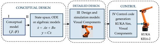
Figure 12.
Diagram of the HS method realization, showing the model’s dynamics of RWC components in the design and control processes.
4. Conclusions
The main aspects of the conceptual model of the robotic work cell (RWC) presented in the formal basis of hierarchical systems (HS) for conceptual design and control implementation are described in the work. The developed RWC conceptual model connects the representation of the RWC structure, aggregated dynamic models of RWC subsystems, and RWC environment using HS technology. The HS coordinator is presented in the form of the RWC coordinator, which performs the design and control tasks. The worked-out RWC conceptual model is aimed at being used at the conceptual design phase of the RWC life cycle. To perform detailed design tasks, the digital model of the RWC was created within the framework of the Visual Components program system environment. The results of the RWC conceptual and detailed design were implemented in the laboratory environment of USP, Brazil, to control the KUKA KR16-2 robot to perform the trajectory-following task.
The originality of the proposed work lies in the application of the novel HS technology in the creation of a conceptual model and design of the selected RWC. The model developed at the conceptual design phase is coordinated with the models used at the detailed design phase and created within the framework of the Visual Components program system. The effectiveness of the proposed HS approach in comparison with other known design, AI, and mathematical methods lies in the possibility of the presentation of the connected models of RWC system structure being designed, its dynamic model, its processes, environment, and coordinating elements in the common theoretical basis of HS, which allows solving RWC synthesis and analysis design problems within the framework of one common formal HS model using the HS coordinator, which connects the structure of system being designed with its function, predicting, in this way, the system’s dynamics in its environment, and performing RWC control. The reliability of the model proposed was verified while performing the design and control tasks of various mechatronic and robotic objects [14,15,16,17,18,19,27]. The proposed method can be adapted to different mechatronic systems. Correspondent examples of the method application in mechatronic design and control are presented in [14] for the cases of biomechatronic surgical robot system design, biologically inspired robot and human motion design, design and control of an MCM cutting machine in an industrial environment, and electronic circuit board (PCB) design and testing. Application of the developed method in other robotic problems [28,29,30,31,32,33,34] is among the future tasks.
Author Contributions
Conceptualization, K.M., M.A.O.P. and P.E.M.; methodology, K.M. and M.A.O.P.; software, K.K. and A.E.; validation, K.M., K.K. and A.E.; formal analysis, K.M.; investigation, K.K. and M.A.O.P.; writing—original draft preparation, K.M., K.K. and M.A.O.P.; writing—review and editing, K.M. and P.E.M.; visualization, K.K. and A.E. All authors have read and agreed to the published version of the manuscript.
Funding
This research was partially funded by the funds of the Faculty of Mechanical Engineering of Bialystok University of Technology, Poland, within the framework of the RID project and original research work WZ/WM-IIM/4/2023.
Data Availability Statement
The original contributions presented in this study are included in the article. Further inquiries can be directed to the corresponding author.
Acknowledgments
The authors express their great gratitude to the vice-rector of the Bialystok University of Technology (BUT), Marek Krętowski, and the Dean of the Mechanical Engineering Faculty, Michal Kuciej, for their support. The Authors would like to thank the Brazilian governmental agencies CAPES, CNPq, and São Paulo Research Foundation (FAPESP)—grant #2020/09850-0 for their partial support of this work.
Conflicts of Interest
The authors declare no conflicts of interest.
References
- Visual Components. Available online: https://www.visualcomponents.com/resources/blog/introducing-visual-components-4-4/ (accessed on 11 February 2025).
- Pokojski, J.; Szustakiewicz, K. Towards an aided process of building a knowledge based engineering applications. Mach. Dyn. Probl. 2009, 33, 91–100. [Google Scholar]
- Mele, M.; Campana, G. A new method for the design of knowledge-based engineering systems for manufacturing. Int. J. Interact. Des. Manuf. 2021, 15, 417–428. [Google Scholar] [CrossRef]
- Sobieszczanski-Sobieski, J.; Morris, A.; Tooren, M. Multidisciplinary Design Optimization Supported by Knowledge Based Engineering; John Wiley & Sons: Hoboken, NJ, USA, 2015. [Google Scholar]
- Papiernik, K.; Grabska, E.; Borkowski, A. On applying model-driven engineering to conceptual design. Mach. Dyn. Probl. 2007, 31, 58–65. [Google Scholar]
- Casalaro, G.L.; Cattivera, G.; Ciccozzi, F.; Malavolta, I.; Wortmann, A.; Pelliccione, P. Model-driven engineering for mobile robotic systems: A systematic mapping study. Softw. Syst. Model. 2022, 21, 19–49. [Google Scholar] [CrossRef]
- Bryant, C.R.; Stone, R.B.; McAdams, D.A.; Kurtoglu, T.; Campbell, M.I. Concept generation from the functional basis of design. In Proceedings of the International Conference on Engineering Design (ICED 2005), Melbourne, Australia, 15–18 August 2005. [Google Scholar]
- Valjak, F.; Nenad Bojčetić, N. Functional modelling through Function Class Method: A case from DfAM domain. Alex. Eng. J. 2023, 66, 191–209. [Google Scholar] [CrossRef]
- Gero, J.S.; Kannengiesser, U. A function–behavior–structure ontology of processes. Artif. Intell. Eng. Des. Anal. Manuf. 2007, 21, 379–391. [Google Scholar] [CrossRef]
- Al-Fedaghi, S. Function-Behavior-Structure model of design: An alternative approach. Int. J. Adv. Comput. Sci. Appl. 2016, 7, 133–139. [Google Scholar] [CrossRef]
- Gausemeier, J.; Ramming, F.J.; Schafer, W. Design Methodology for Intelligent Technical Systems; Springer: Berlin/Heidelberg, Germany, 2014. [Google Scholar]
- Kühn, A.; Dumitrescu, R.; Gausemeier, J. Managing evolution from mechatronics to intelligent technical systems. J. Technol. 2015, 76, 13–18. [Google Scholar] [CrossRef][Green Version]
- Legatiuk, D.; Nilsson, H. Abstract modelling: Towards a typed declarative language for the conceptual modelling phase. In Proceedings of the 8th International Workshop on Equation-Based Object-Oriented Modeling Languages and Tools, Munich, Germany, 1 December 2017; pp. 61–64. [Google Scholar]
- Miatliuk, K. Conceptual Design of Mechatronic Systems; WPB: Bialystok, Poland, 2017; Available online: https://pb.edu.pl/oficyna-wydawnicza/wp-content/uploads/sites/4/2018/02/Miatluk_publikacja.pdf (accessed on 11 February 2025).
- Miatliuk, K.; Kim, Y.H.; Kim, K.; Siemieniako, F. Use of Hierarchical System Technology in Mechatronic Design. J. Mechatron. 2010, 20, 335–339. [Google Scholar] [CrossRef]
- Miatliuk, K. Conceptual Model in the Formal Basis of Hierarchical Systems for Mechatronic Design. J. Cybern. Syst. 2015, 46, 666–680. [Google Scholar] [CrossRef]
- Miatluk, K.; Nawrocka, A.; Holewa, K.; Moulianitis, V. Conceptual Design of BCI for Mobile Robot Control. Appl. Sci. 2020, 10, 2557. [Google Scholar] [CrossRef]
- Miatliuk, K.; Wolniakowski, A.; Trochimczuk, R.; Jorgensen, J. Mechatronic Design and Control of a Robot System for Grinding. In Proceedings of the 20th IEEE/ASME International Conference on Mechatronic and Embedded Systems and Applications, Genova, Italy, 2–4 September 2024; pp. 1–6. [Google Scholar]
- Miatliuk, K.; Wolniakowski, A.; Quintana, J.J. Conceptual Design and Control of a Robotic System for Welding. In Proceedings of the 24th IEEE International Carpathian Control Conference, Miskolc-Szilvásvárad, Hungary, 12–14 June 2023; pp. 279–284. [Google Scholar]
- RobotStudio. Available online: https://new.abb.com/products/robotics/robotstudio (accessed on 11 February 2025).
- CoppeliaSim. Available online: https://www.coppeliarobotics.com/ (accessed on 11 February 2025).
- DELMIA. Available online: https://www.cadsol.pl/produkty/delmia/ (accessed on 11 February 2025).
- RoboDK. Available online: https://robodk.com/ (accessed on 11 February 2025).
- Archila, J.F.; Dutra, M.S.; Castro Pinto, F.A. Kinematical and Dynamical Models of KR 6 KUKA Robot, Including the Kinematic Control in a Parallel Processing Platform. In Robot Manipulators, New Achievements; IntechOpen: Rijeka, Croatia, 2010; pp. 601–620. [Google Scholar]
- TongTai. Available online: https://www.tongtai.com.tw/en/product-detail.php?id=138 (accessed on 11 February 2025).
- KUKA. Available online: https://www.robots.com/images/robots/KUKA/Low-Payload/KUKA_KR_16_2_F_Datasheet.pdf (accessed on 11 February 2025).
- Miatliuk, K.; Wolniakowski, A.; Kolosowski, P. Engineering system of systems conceptual design in theoretical basis of hierarchical systems. In Proceedings of the IEEE International Conference Systems Man and Cybernetics SMC, Toronto, ON, Canada, 11–14 October 2020; pp. 2850–2856. [Google Scholar]
- Wolniakowski, A.; Miatliuk, K.; Kruger, N.; Petersen, H.; Ritz, J. Task and context sensitive gripper design learning using dynamic grasp simulation. J. Intell. Robot. Syst. 2017, 87, 15–42. [Google Scholar] [CrossRef]
- Valsamos, C.; Miatluk, K.; Wolniakowski, A.; Moulianitis, V.; Aspragathos, N. Optimal kinematic task position determination–application and experimental verification for the UR5 manipulator. Appl. Sci. 2022, 12, 9352. [Google Scholar] [CrossRef]
- Diaz, M.; Ferrer, M.A.; Quintana, J.J.; Miatliuk, K.; Wolniakowski, A.; Vessio, G.; Trochimczuk, R.; Castellano, G. Neural network modelling of kinematic and dynamic features for signature verification. Pattern Recognit. Lett. 2025, 187, 130–136. [Google Scholar] [CrossRef]
- Trochimczuk, R.; Wolniakowski, A.; Cheng, Z.; Romaniuk, S.; Tomaszewski, R. Overview of selected teleoperation positioning systems for controlling a robot arm operating in Remote Centre of Motion (RCM) mode. In Proceedings of the 28th IEEE International Conference on Methods and Models in Automation and Robotics, Miedzyzdroje, Poland, 27–30 August 2024; pp. 253–258. [Google Scholar]
- Dimeas, F.; Sako, D.; Moulianitis, V.; Aspragathos, N. Design and fuzzy control of a robotic gripper for efficient strawberry harvesting. Robotica 2015, 33, 1085–1098. [Google Scholar] [CrossRef]
- Mystkowski, A.; Wolniakowski, A.; Idzkowski, A.; Ciezkowski, M.; Ostaszewski, M.; Kociszewski, R.; Kotowski, A.; Kulesza, Z.; Dobrzański, S.; Miastkowski, K. Measurement and diagnostic system for detecting and classifying faults in the rotary hay tedder using multilayer perceptron neural networks. Eng. Appl. Artif. Intell. 2024, 133, 108513. [Google Scholar] [CrossRef]
- János Simon, J.; Gogolák, L.; Sárosi, J. Deep Reinforcement Learning-Assisted Teaching Strategy for Industrial Robot Manipulator. Appl. Sci. 2024, 14, 10929. [Google Scholar] [CrossRef]


Disclaimer/Publisher’s Note: The statements, opinions and data contained in all publications are solely those of the individual author(s) and contributor(s) and not of MDPI and/or the editor(s). MDPI and/or the editor(s) disclaim responsibility for any injury to people or property resulting from any ideas, methods, instructions or products referred to in the content. |
© 2025 by the authors. Licensee MDPI, Basel, Switzerland. This article is an open access article distributed under the terms and conditions of the Creative Commons Attribution (CC BY) license (https://creativecommons.org/licenses/by/4.0/).