Abstract
Corrosion of nickel alloys in molten salts is a complex process dependent on many factors. The paper describes the influence of microstructural changes in several nickel-based alloys (Hastelloy® G-35®, VDM® Alloy 59, KhN62M-VI, Hastelloy® B-3®) on the mechanism of their corrosion in molten fluoride salts. The corrosion experiments were performed in LiF–NaF–KF and (LiF–NaF–KF) + UF4 melts at 550–750 °C. Formation of excess secondary phases along the grain boundaries of the alloys led to heterogeneity of the alloy microstructure. As a result of these changes, microgalvanic couples formed on the surface of the alloys, leading to the development of intergranular corrosion upon contact with molten electrolytes. Secondary phases acted as microanodes or microcathodes depending on a number of factors. Formation and composition of the secondary phases affected the depth and extent of the corrosion damage to nickel alloys.
1. Introduction
Molten salts exhibit a broad spectrum of properties, rendering them highly suitable for application in advanced energy generation and storage systems. The benefits of molten salt–based systems, particularly for nuclear industry applications, arise from their physical and chemical properties: high boiling point and, as a consequence, low vapor pressure; good heat transfer capacity; wide electrochemical stability window; resistance to ionizing radiation; absence of neutron moderators; and good solubility of actinide compounds [1,2,3,4].
Currently, two primary technological frontiers are advancing towards the application of molten salts in power engineering on a semi-industrial scale: in concentrated solar power (CSP) systems and in the nuclear industry as primary or secondary coolants in both fission and fusion systems, as well as the media for spent nuclear fuel reprocessing [5,6,7,8,9,10,11,12,13,14]. Molten salt reactor (MSR) technology was initially demonstrated in the 1950s to 1960s at ORNL [15]; significant renewed interest and research efforts were notably intensified from the 2010s [16]. The gap between the initial historical demonstration of the technology and the current renaissance is attributed to a number of factors, including unresolved issues with insufficient corrosion resistance of the construction materials, the complexity of operating molten salt reactors, and the substantial level of funding required for implementing such nuclear power installations. The comprehensive spectrum of challenges associated with the deployment of MSRs is described in the IAEA Technical Report 489 [17]. One of the critical issues is the lack of suitable structural materials capable of withstanding prolonged operation under the severe conditions inherent to MSR systems. Two types of molten salt systems are considered for use in MSRs, i.e., based on fluorides, which were tested in the past, and chlorides, which are considered as prospective working media. Among fluorides, there are two principal compositions of the solvent melt—a mixture of lithium and beryllium fluorides (FLiBe) and the ternary eutectic mixture of lithium, sodium, and potassium fluorides (FLiNaK) [18]. The latter salt is more promising because it is characterized by higher solubility of actinide fluorides [19,20,21]. The current research focused on studying structural material compatibility with FLiNaK-based molten fluoride salts.
Possible causes of corrosion in molten halide media have been extensively investigated worldwide [22,23,24,25,26,27,28,29,30,31,32,33,34,35,36,37,38,39]. The primary factors influencing corrosion are generally considered to be the exposure temperature, the nature of the fused electrolytes, the type and content of impurities in the salt, the purity of the surrounding atmosphere (presence of moisture and oxidants), and the composition of the structural material itself. Despite numerous studies, insufficient attention has been devoted so far to the effect of the microstructure of the materials on their corrosion resistance. Existing data concerning corrosion phenomena in molten halides and material structure are somewhat controversial and do not allow a sensible connection between an alloy’s internal structure changes and its corrosion performance in a molten salt environment to be established. For example, aging the Ni-based alloy VDM® Alloy C-4 at 550 °C for 2500 h resulted in the formation of a Ni2(Cr,Mo) phase, which showed some positive effect on the alloy’s corrosion resistance in an acidic KCl–AlCl3 melt [39]. Improvement in the corrosion resistance of a C-4 type alloy in the same melt aligned well with the results of Tawancy and Alhems [40] for aqueous systems. They also observed that the rate of corrosion of a C-4 type alloy with a long-range ordered (LRO) structure was lower compared to its initial annealed state. Formation of dispersion hardening particles of the Ni2(Cr,Mo) ordered phase led to a reduction in the alloy’s corrosion equilibrium potential, primarily due to enhanced interatomic interactions [39].
However, in a study of a model Ni–33 at. % Cr alloy corrosion, Fei Teng et al. [41] observed degradation of a Ni2Cr (MoPt2-type) long-range ordered phase within the Ni–Cr binary system. They reported that the formation of the Ni2Cr phase accelerated the corrosion process in molten chlorides. This acceleration was attributed to two primary factors: the anisotropic corrosion behavior of the LRO phase and the internal lattice strain induced by the LRO structure. In another study [42], the same authors declared that the cold-rolling process increased the susceptibility of 316 L steel to corrosion in molten FLiNaK salt.
Muransky et al. [43] investigated the impact of microstructural changes under plasticity-imparting conditions on alloy corrosion performance in molten salts. They showed that the stored dislocations and dislocation substructures formed during high-temperature creep (HTC) facilitated mass transfer towards the corrosion-affected layer through intragranular diffusion of the alloying elements. Subsequently, the recrystallized fine-grained microstructure of the corrosion-affected layer enhanced transfer to the salt-exposed surface via intergranular diffusion. This enhanced mass diffusion accelerated molten salt corrosion of the alloy, significantly shortening its lifespan under operational conditions.
However, it appears that one of the most significant microstructural changes that affects intergranular corrosion (IGC) is the formation of carbide or topologically close-packed (TCP) phases. Metallographic analysis of samples of AISI 316 steel after corrosion tests in a LiF–BeF2 melt at 700 °C revealed the presence of grain boundary precipitation of the Cr7C3 phase, thus confirming carbon and chromium diffusion towards the grain boundaries, causing subsequent initiation of IGC processes [33]. Similarly, IGC was detected in AISI 316L, 316Ti, and 321 austenitic stainless steels after their exposure in melts based on a NaCl–KCl equimolar mixture at 750 °C [44]. The authors proposed a mechanism of corrosion of stainless steels in molten chlorides that includes the following stages: deposition of chromium-containing carbides along the grain boundaries and formation of galvanic pairs between the chromium-depleted parts of the grains of austenitic alloys and the carbide phases. Later, the same authors indicated that intermetallic topologically close-packed χ phases containing chromium and molybdenum were formed in low-carbon steels as a result of heating to 750 °C, also inducing IGC processes [45].
The corrosion behavior of the corrosion-resistant alloy Hastelloy® G-35®, the corrosion and heat-resistant alloy VDM® Alloy 600 or Nicrofer® 7216, and the corrosion-resistant alloys VDM® Alloy C-4 or Nicrofer® 6616 and VDM® Alloy 625 or Nicrofer® 6020 was also investigated in fused KCl–AlCl3 at 450–650 °C with exposure times of up to 1000 h [46]. Increasing temperature noticeably increased the corrosion rates and changed the corrosion process nature. Transmission electron microscopy revealed that Me23-nCrnC6 type carbides (for VDM® Alloy 600) and intermetallic TCP phases (such as sigma-phase in case of Hastelloy® G-35®, VDM® Alloy C-4, and VDM® Alloy 625) were formed during prolonged high-temperature exposure. These phenomena can accelerate intergranular corrosion and stress corrosion cracking of materials under industrial conditions.
The aims of the current investigation were to conduct preliminary corrosion tests on various corrosion-resistant nickel-based alloys in FLiNaK-based melts under inert atmosphere and static conditions and perform detailed analysis of the effects of microstructural changes on the corrosion resistance of nickel-based alloys as prospective structural materials for molten salt reactors.
2. Experimental
In the present study, tests for determining the corrosion properties of materials were carried out under static conditions (ampoule corrosion tests). The corrosion tests were conducted in FLiNaK-based melts. In a number of experiments, uranium tetrafluoride was added to the melt to assess the effect of the MSR main fuel component on the corrosion performance of the construction materials. The procedure for synthesis of FLiNaK was described earlier [47,48].
Uranium (IV) fluoride was prepared from uranyl sulfate (UO2SO4·3H2O, depleted in U-235). First, uranium was reduced to an oxidation state of +4. High-purity iron powder was added to an acidified solution of uranyl sulfate to enable the reduction:
UO22+ + Fe + 4H+ → U4+ + Fe2+ + 2H2O
Any excess of iron was dissolved in the sulfuric acid present in the solution. Then, uranium tetrafluoride was precipitated by adding an excess solution of hydrofluoric acid:
U4+ + 4F− + nH2O → UF4‧nH2O.
Precipitated hydrate of uranium fluoride was washed four times with a hot 1% solution of hydrofluoric acid and then twice with distilled water. The solid was dried in air at 150 °C to remove the moisture and then dehydrated by two-stage heating under vacuum, first at 360 °C for 2 h and then at 550 °C for 1 h. The phase composition of uranium tetrafluoride was confirmed by X-ray powder diffraction analysis (PANalytical X’Pert Pro MPD, PANalytical, Almelo, The Netherlands).
Fluoride salts (the mixture of lithium, sodium, and potassium fluorides) used as the corrosive media are hygroscopic. All operations involving FLiNaK, including synthesis of the eutectic mixture, grinding, loading, and storage were carried out in a glovebox (Glovebox Systemtechnik GmbH, Malsch, Germany) in an argon atmosphere (<4 ppm O2 and <0.1 ppm H2O). The FLiNaK + UF4 salt system was prepared by mixing the salts in a FLiNaK-to-UF4 mass ratio of 93.4:6.6. Salts were mixed in the glovebox and then fused together at 850 °C in the furnace located inside the glovebox. The salts were kept at said temperature for 2 h to homogenize the melt.
The chemical composition of the electrolytes is presented in Table 1, and the impurity content is shown in Table 2. The results from the chemical analysis showed that addition of uranium fluoride to FLiNaK did not lead to a significant increase in the impurity content, thus confirming the purity of the synthesized UF4.

Table 1.
Chemical composition of electrolytes, wt. %.
Table 2.
Initial content of impurities in the salt electrolytes, ppm.
The corrosion experiments were performed at a temperature range of 550–750 °C using a custom-built setup that included a set of steel cells closed using water-cooled lids; each cell connected to a gas-vacuum system and was heated by an external resistance furnace. The tests were performed in a high-purity argon (99.9998%) atmosphere with controlled temperature and pressure inside the retort. The setup and the methodology for conducting ampoule corrosion tests were described in detail previously [47,48]. This setup allows long-term corrosion tests to be performed in various working media at elevated temperatures.
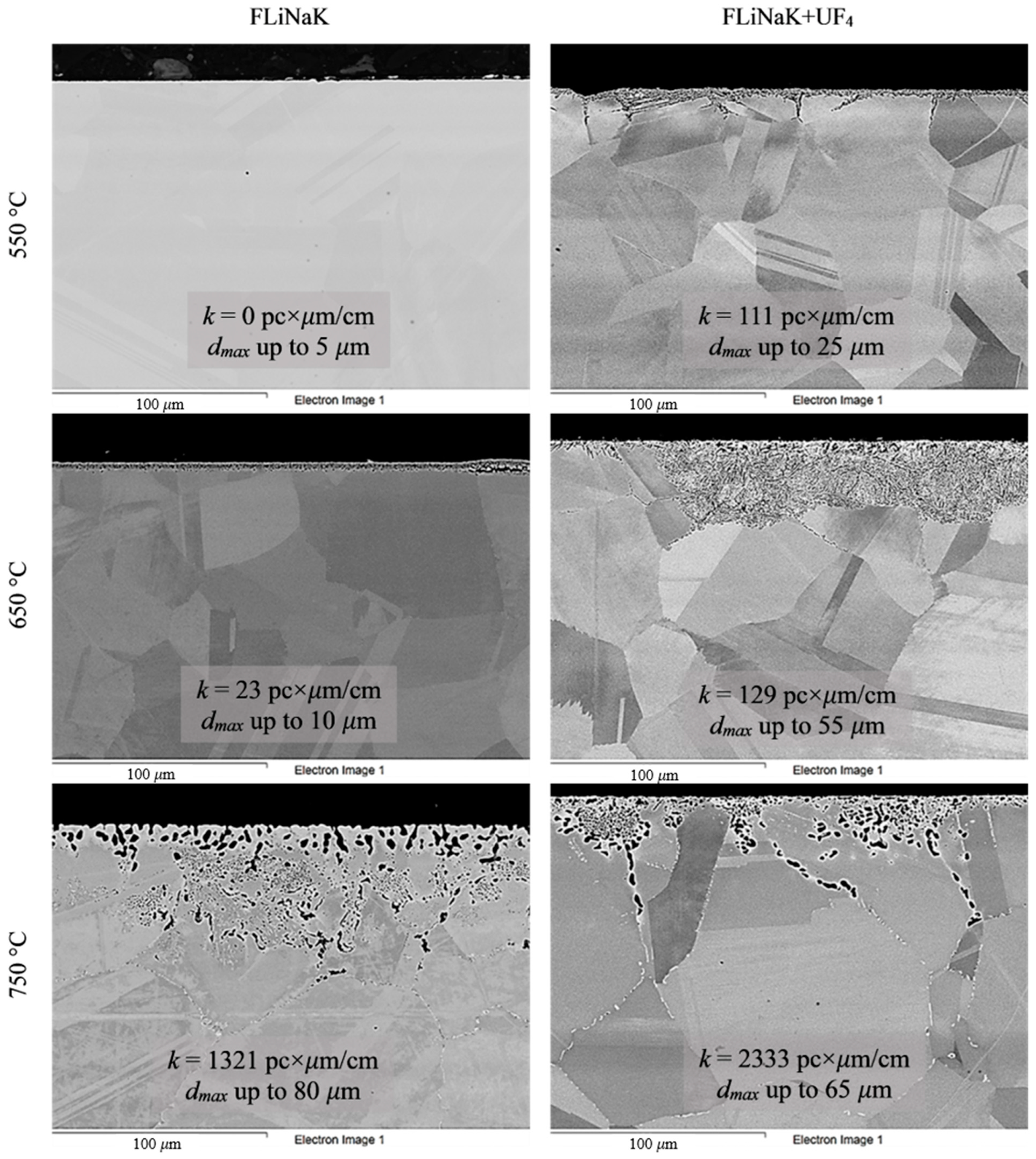
Three samples of each alloy were used in the corrosion experiments. The weight of the samples was recorded prior to the test. The samples were placed in the crucibles and covered with the required amount of powdered salt. The crucibles were then covered with lids. The loading procedure was performed in an argon-filled glove box. The crucibles were transferred into stainless-steel cells, which could be tightly closed using steel lids. A metallic titanium sponge was positioned above the crucible lid in each cell to act as a getter for additional purification of the atmosphere from possible oxygen contamination. A schematic of the experimental cell used for the corrosion studies is shown in Figure 1.
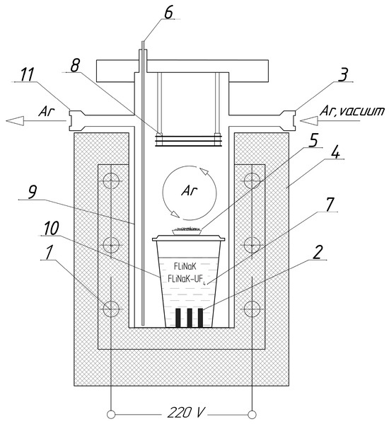
Figure 1.
Experimental setup for corrosion experiments: (1) heating elements; (2) test sample; (3) gas inlet; (4) furnace; (5) titanium sponge getter; (6) thermocouple; (7) molten salt; (8) nickel heat reflecting screens; (9) steel cell; (10) crucible; (11) gas outlet.
Each assembled cell was evacuated, filled with high-purity argon (99.9998%), and placed in a vertical tube furnace. A continuous argon flow of approximately 45 mL/min was maintained through the upper part of the cell throughout the experiment. The cells were heated to 650 °C, with the temperature monitored by a thermocouple positioned near the crucible (Figure 1), and held at this temperature for 100 h. This was sufficient for assessment of the corrosion processes and estimation of their mechanisms.
After the experiment, the cells were cooled to room temperature and opened in the glovebox. The crucibles containing the samples were retrieved, and the alloy specimens were carefully separated from the molten salt. The samples were then washed sequentially with 1 M Al(NO3)3 solution and deionized water, dried, and weighed to determine mass loss. The weight change was used to calculate the corrosion rate using this gravimetric method (GM).
The concentrations of micro- and macro-components and the contents of impurities and corrosion products in the salt phase were determined using X-ray fluorescence analysis (ARL ADVANT’X 4200, ThermoFisher Scientific, Basel, Switzerland) and atomic emission spectrometry with inductively coupled plasma (Optima 2100DV, PerkinElmer, Wallingford, CT, USA). The oxygen content of the salt was determined by the method of carrier gas hot extraction (Horiba EMGA 620W/C, Horiba, Kyoto, Japan). The results from the chemical analysis allowed independent calculation of the corrosion rate values based on the mass fraction of corrosion products in the salt system (subsequently referred to as the chemical method, ChM).
For metallographic analysis, the specimens were mounted in phenol hot-mounting resin with carbon filler. Mounted samples underwent grinding in six stages using SiC papers of progressively finer grades (80 → 220 → 320 → 1200 → 2400 → 4000 grit), followed by polishing with a water-based 1 µm diamond suspension (DiADuo-2, Struers, Copenhagen, Denmark) and a final polish with colloidal silica suspension (OP-S, Struers). No etching of samples was performed.
The microstructure of the samples before and after the tests was examined by scanning electron microscopy (Zeiss Auriga CrossBeam (Carl Zeiss NTS, Oberkochen, Germany) and JSM 6490 (Tokyo, Japan) with an Oxford Inca X-Ray microanalysis setup) and optical microscopy (Olympus GX-71F, Tokyo, Japan) to assess the presence of inclusions and excess phases, as well as the nature and depth of corrosion. After the corrosion tests, the degree of intercrystalline damage, characterized by the value of the “k-parameter”, was also determined. For this purpose, microstructure images of the sample surface of at least 0.1 cm in length (l, cm) were analyzed, and the number of cracks (n, pc) and their depth (d, µm) were recorded. When cracks were not seen on the surface of the studied samples, the k-parameter was taken to be zero. Otherwise, the arithmetic mean (daver., µm) was calculated for all recorded cracks, and the k-parameter (pc. × µm/cm) was calculated using the following formula (a detailed description of the applied method was given previously [49]):
k = n·daver./l.
In the present study, four industrial nickel-chromium-molybdenum–based corrosion-resistant low-carbon alloys were tested, as shown in Table 3. These alloys can be categorized into different families depending on chromium and molybdenum content. Hastelloy® G-35® is the alloy from the G-group and is characterized by higher chromium content. VDM® Alloy 59 and the Russian alloy KhN62M-VI [50] belong to the C-family. The last alloy, Hastelloy® B-3®, represents B-family, with increased molybdenum content and low chromium content. The G-family was designed for application in highly oxidizing aqueous systems, the C-group family offers versatility in both oxidizing and reducing media, while the B-family excels in reducing environments [51]. The possibilities of their application at relatively high temperatures in contact with aggressive molten halides are still not clear and require deeper investigation.
Table 3.
Chemical composition of the studied nickel-chromium-molybdenum alloys.
The composition of the alloys in their ‘as received’ state (according to the manufacturer’s data) is listed in Table 3. Analysis of the structure of the alloys in the initial state was also carried out (Figure 2). The microstructure of the Hastelloy® G-35® (Haynes, Kokomo, IN, USA), VDM® Alloy 59 (VDM─Metals, Werdohl, Germany), KhN62M-VI (RUSPOLYMET, Kulebaki, Russia), and Hastelloy® B-3® (Haynes, Kokomo, IN, USA) alloys in the ‘as received’ state represented a nickel-based fcc solid solution with a small amount of inclusions, which is typical for this class of materials [51].
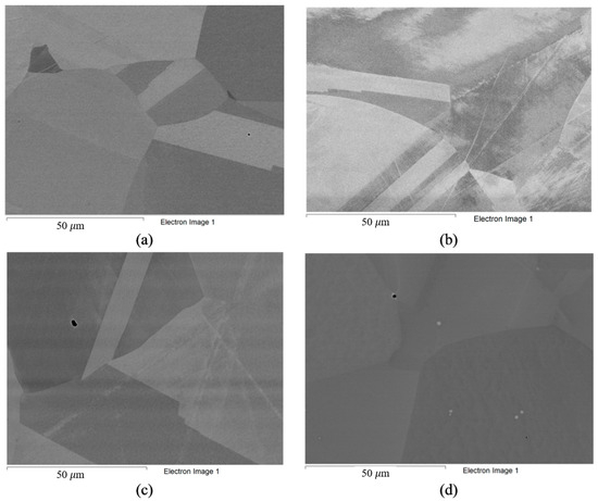
Figure 2.
Microstructure of alloys in ‘as received’ state: (a) Hastelloy® G-35®; (b) VDM® Alloy 59; (c) KhN62M-VI; (d) Hastelloy®B-3®.
3. Results and Discussion
The employment of nickel alloys in fluoride melts, in contrast to aqueous media, inevitably introduces the problem of high temperatures, normally around 550–750 °C. In this case, the key role in the corrosion processes is played not by the increase in the kinetics of chemical reactions between the alloy components and the salt melt but by phase changes that occur in the bulk of the alloys at high rates at these temperatures. Under thermal influence, the studied alloys with initially homogeneous structure are transformed into heterogeneous systems. Such transformation can lead to the precipitation of excess phases of various nature along grain boundaries or long-range ordered structures [46,52,53,54,55,56,57,58,59,60,61,62]. The tendency to form grain boundary precipitation increases with as the temperature increases from 550 to 750 °C [46,52,55,56,58,59,61,62]. For example, no secondary chain phases were observed below 550 °C in Hastelloy® G-35® subjected to up to 1000 h of thermal exposure [46]. Increasing the temperature to 650 °C can lead to the formation of various secondary phases (σ, P, α-chromium, etc.) at the grain boundaries of the studied alloys [46,52,58,60,61], and the time required for the development of such phases in Hastelloy® G-35® is up to 100 h [46]. At 750 °C, the chain precipitates are formed at a significant rate (the time of formation of precipitates in Hastelloy® G-35® is up to 10 h), resulting in the intensification of corrosion processes [46].
The corrosion rates and maximum damage depth (dmax) of the materials after 100 h corrosion tests in FLiNaK-based salt systems (with and without uranium tetrafluoride addition) at different temperatures are presented in Table 4 and Figure 3.
Table 4.
Corrosion rates (CRs) calculated using different approaches (GM and ChM) and maximum damage depth (dmax) of studied alloys after 100 h corrosion tests in FLiNaK and FLiNaK + UF4.
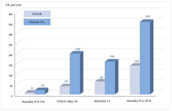
Figure 3.
Corrosion rates of the studied alloys after 100 h corrosion tests in FLiNaK and FLiNaK + UF4 at 650 °C (GM).
The content of corrosion products in the salt melts after the corrosion tests is summarized in Table 5. Chromium species were the main corrosion products. Chromium, as the most electronegative element in the alloys, determined the corrosion rates and the degree of corrosion damage. The relatively high content of iron, a minor alloy component, in the corrosion products also confirmed the electrochemical nature of the corrosion processes in molten halides.
Table 5.
Content of the corrosion products in FLiNaK and FLiNaK + UF4 after 100 h corrosion tests, ppm.
The corrosion rate measurements revealed three patterns common to all of the alloys: (a) the corrosion rate increased with increasing oxidizing capacity of the medium; (b) the corrosion rate increased with increasing chromium content in the alloys; and (c) the corrosion rate increased with increasing test temperature. In the first instance, uranium tetrafluoride increased the oxidizing ability of FLiNaK. Uranium is a polyvalent metal and capable of forming ions in different oxidation states in fluoride melts. Here, U(IV) can be reduced to U(III) in the presence of metals or alloy components. The redox potential of the U(III)/U(IV) couple in systems containing predominantly U(IV) is shifted to the region of positive values; therefore, the FLiNaK + UF4 salt system is more aggressive than pure FLiNaK. The second pattern is associated with the phenomenon of selective etching of more negative components from the alloy. In Ni–Cr–Mo systems, chromium is oxidized first [62,63,64,65,66,67]. On the other hand, increasing the temperature leads both to growth of the corrosion rate and formation of secondary phases at the grain boundaries, inducing IGC processes.
To analyze the microstructural changes in the alloys, the samples were subjected to SEM analysis after the corrosion tests. Figure 4, Figure 5, Figure 6, Figure 7 and Figure 8 show images of the materials’ microstructure after exposure in FLiNaK-based melts.
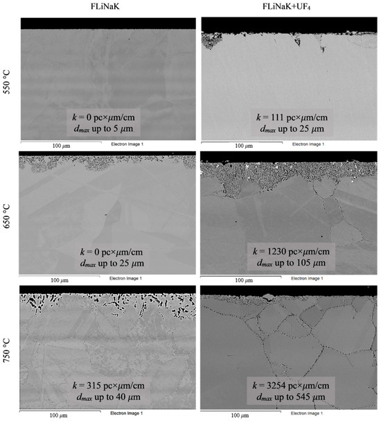
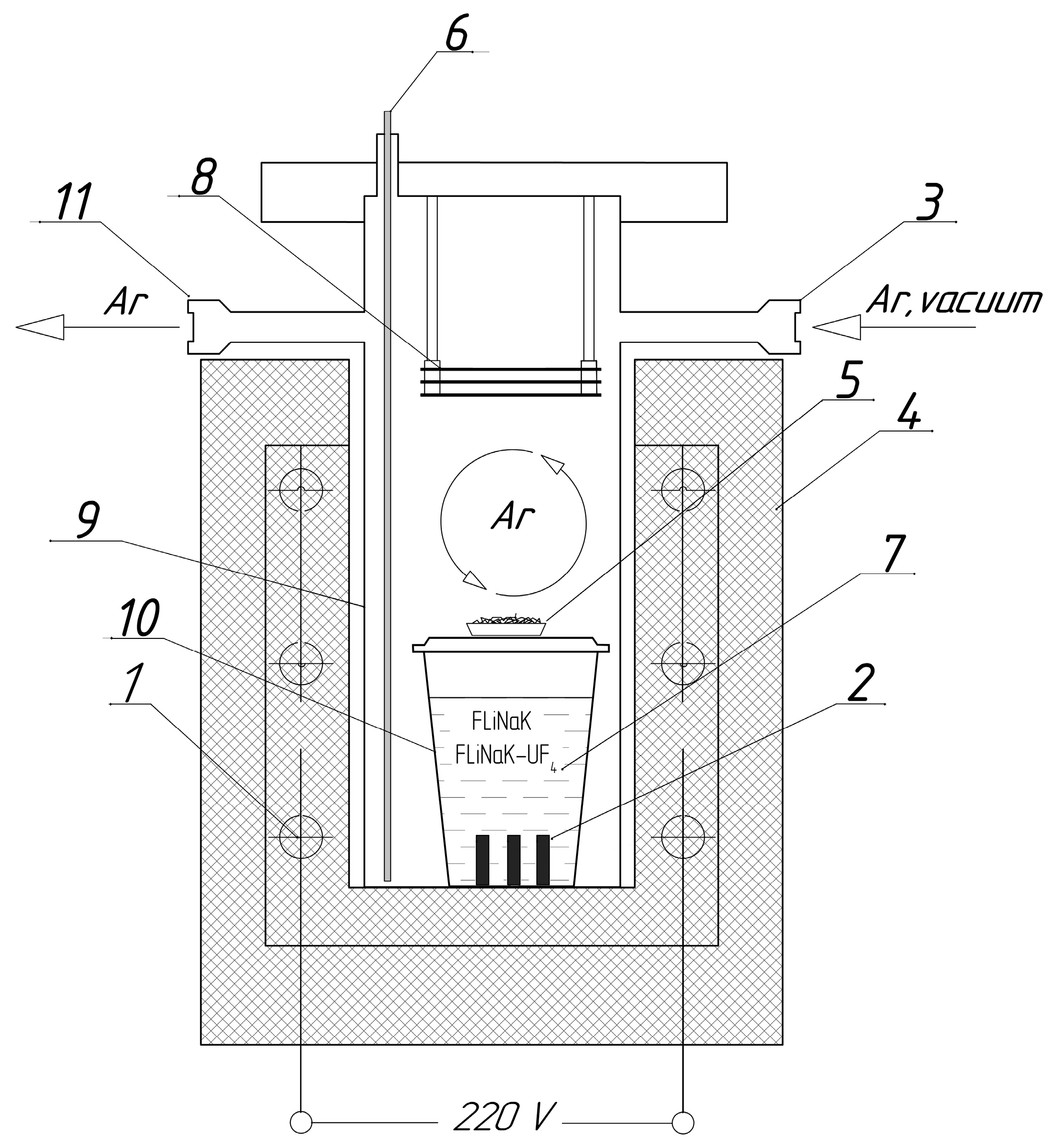
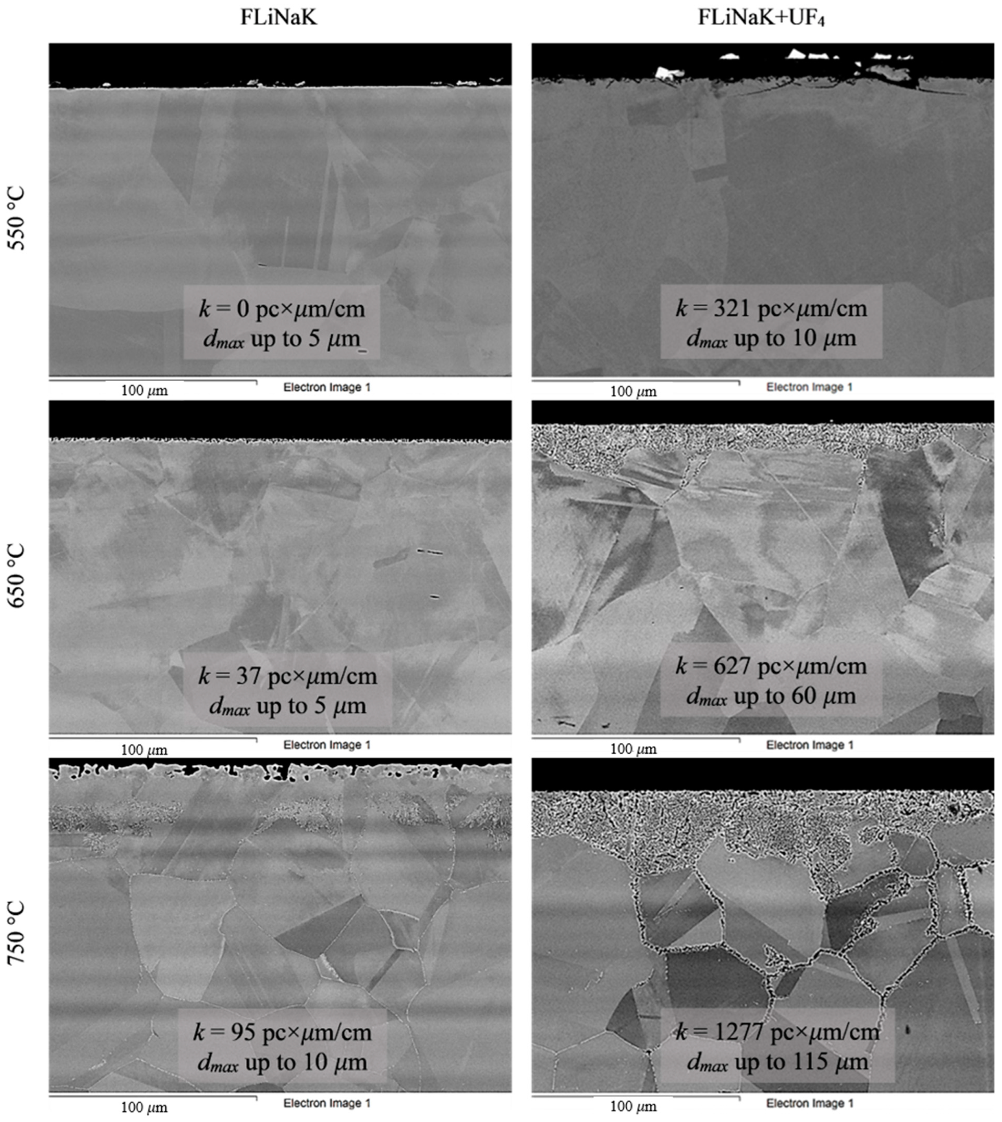
Figure 4.
Microstructure images of Hastelloy® G-35® alloy samples after 100 h corrosion tests in FLiNaK and FLiNaK + UF4 melts at different temperatures.
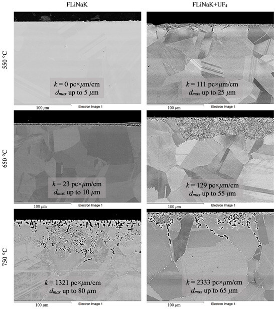
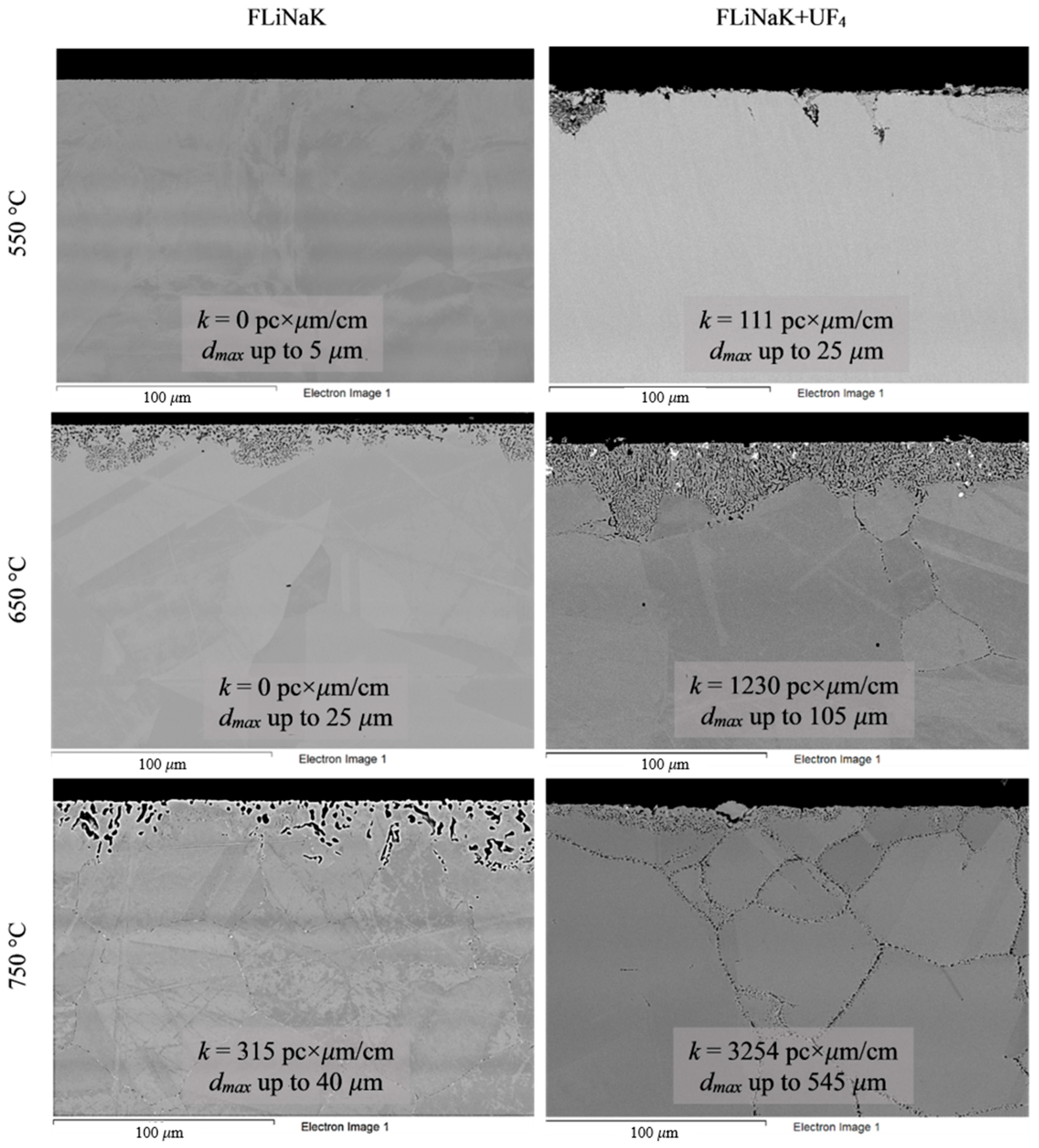
Figure 5.
Microstructure images of KhN62M-VI alloy samples after 100 h corrosion tests in FLiNaK and FLiNaK + UF4 melts at different temperatures.
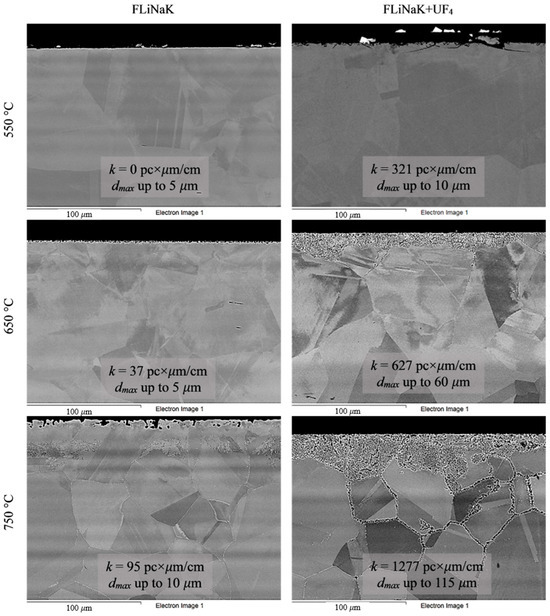
Figure 6.
Microstructure images of VDM® Alloy 59 alloy samples after 100 h corrosion tests in FLiNaK and FLiNaK + UF4 melts at different temperatures.
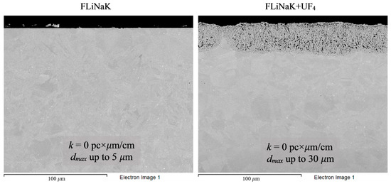
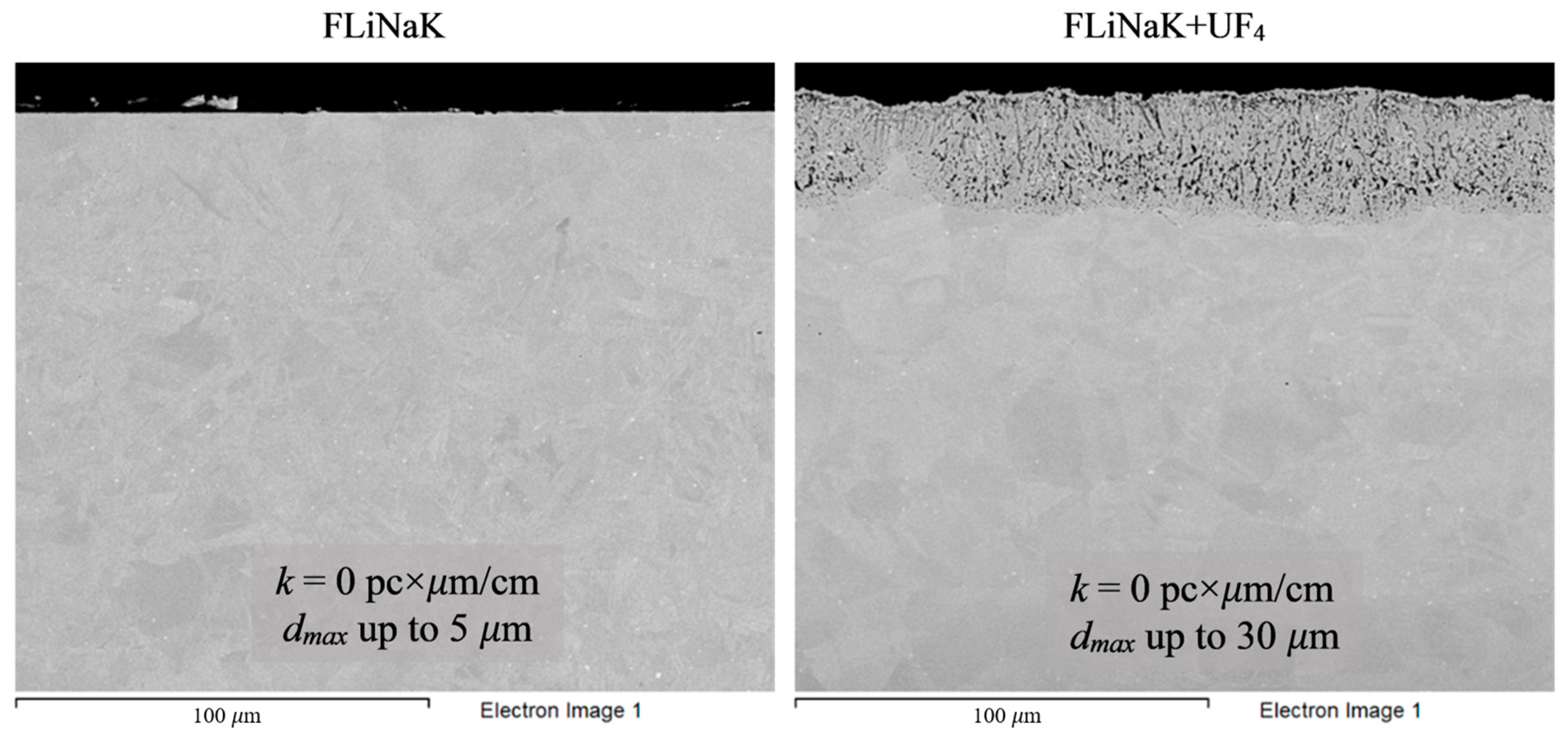
Figure 7.
Microstructure images of Hastelloy® B-3® alloy samples after 100 h corrosion tests in FLiNaK and FLiNaK + UF4 melts at 650 °C.
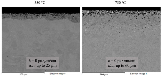
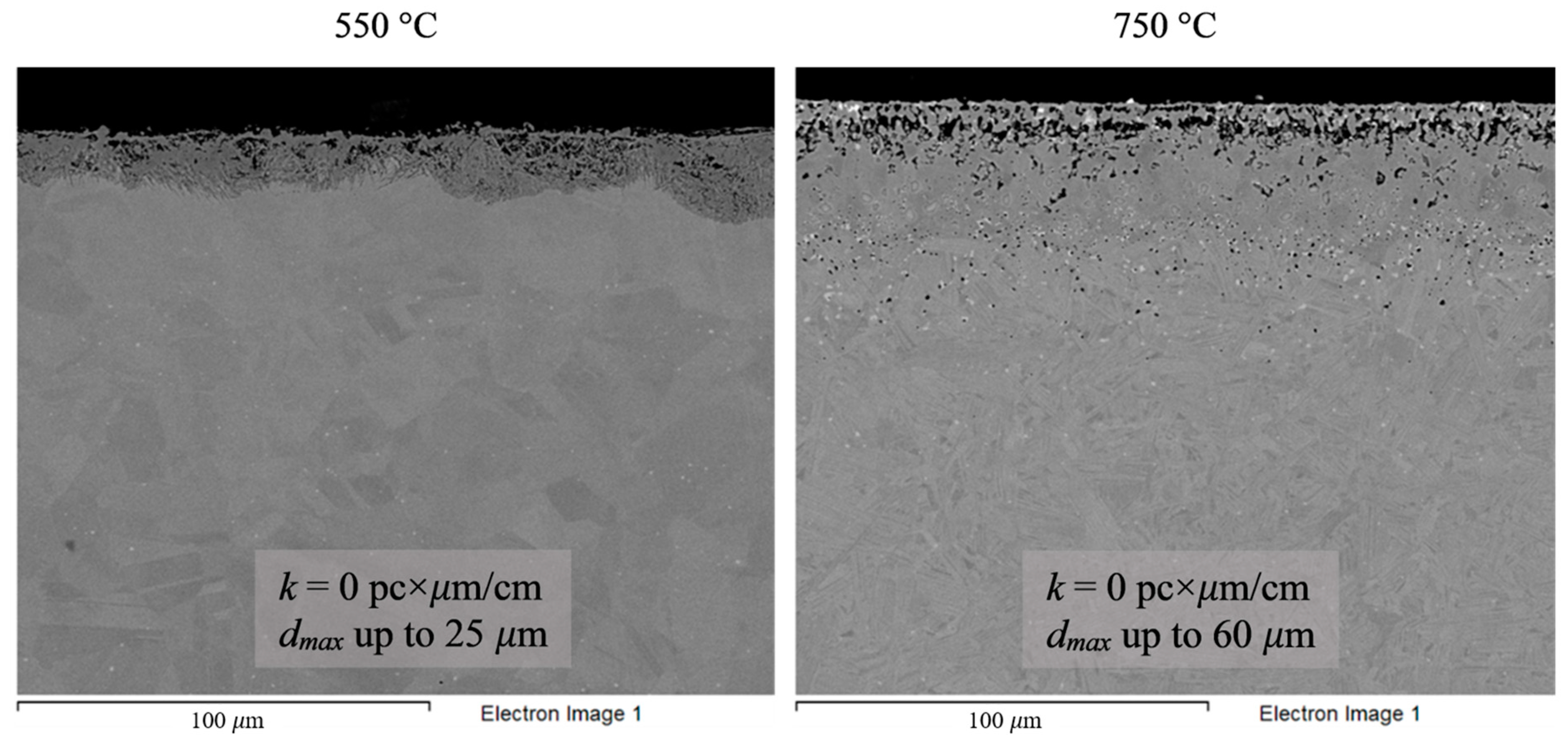
Figure 8.
Microstructure images of Hastelloy® B-3® alloy samples after 100 h corrosion tests in FLiNaK + UF4 melts at 550 and 750 °C.
Analysis of the images shown in Figure 4, Figure 5, Figure 6, Figure 7 and Figure 8 confirms previous conclusions that the degree of destruction of the materials increased with increasing temperature and oxidizing ability of the salt environment. After tests conducted in pure FLiNaK at 550 °C, all samples exhibited continuous uniform surface damage. In the FLiNaK + UF4 salt system at the same temperature, the onset of localization of corrosion processes was observed for all alloys except Hastelloy® B-3®; the corrosion penetration depth (dmax), however, had low values. At 750 °C, intergranular corrosion was observed on all alloys except Hastelloy® B-3®. The main reason for the development of IGC was the precipitation of excess phases along the grain boundaries. Thermal exposure led to the formation of secondary phases in the alloys. As a rule, this process intensifies at temperatures exceeding 600 °C, and this was confirmed by the results shown in Figure 4, Figure 5, Figure 6, Figure 7 and Figure 8. The formation of excess phases led to heterogeneity in the alloy structure. The nature of the formation of secondary phases can be different. The secondary phases can segregate into separate phases, and can form chain arrangements or streaks. Examples of the distribution of excess phases along the grain boundaries in nickel alloys are shown in Figure 9.
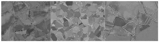
Figure 9.
Types of distribution of excess phases along grain boundaries.
The formation of excess chain-type phases is the most dangerous case when the material is held in contact with an electrolyte, in particular with a salt melt. In this case, the excess phases are interconnected in a continuous grid. In the zone of contact of the alloy’s surface with the electrolyte, microgalvanic couples are formed, where the alloy’s grain and the excess phase act as microelectrodes. In reality, the system can be more complex, since, in addition to the excess phase and the alloy’s grain, a depletion zone is formed, and the alloy’s components diffuse from this zone to the grain boundary while the excess phases are formed. Thus, when excess phases are formed along the grain boundaries, a multielectrode system is formed, in which an anode and a cathode are present. The microanode is the phase with a lower electrode potential, and the more electropositive phase becomes the microcathode. The electrode potential of the microphase is determined by a number of factors, such as chemical composition, phase structure, presence of defects, and deformations. In addition, the formation of excess phases can provoke the occurrence of mechanical stresses along the grain boundaries, which can cause the development of IGC and intergranular stress corrosion (IGSC). Thus, the occurrence of heterogeneity along the grain boundaries of nickel alloys is a destabilizing factor that provokes more intense destruction of the material.
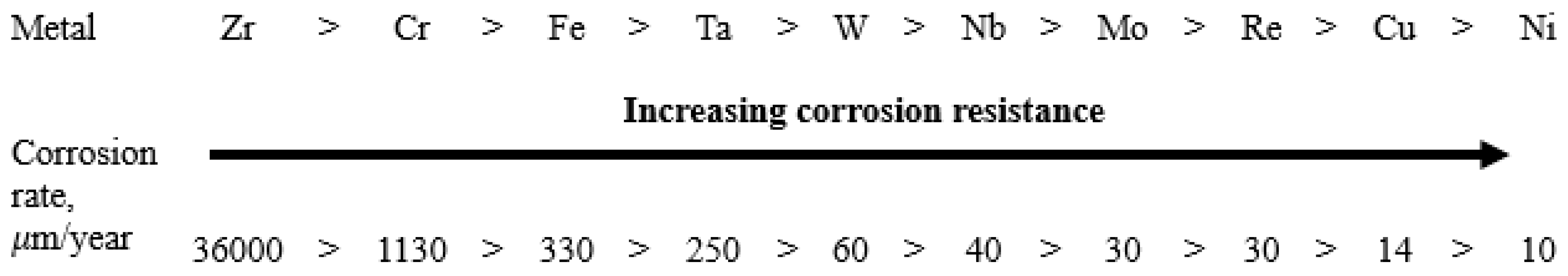
The chemical composition of excess phases can be used to roughly predict the role of the phase in the resulting microgalvanic system if we extrapolate the values of the corrosion rates of individual metals to the chemical composition of the excess phases. A separate series of corrosion tests was conducted with various individual metals (over 99% purity) in molten FLiNaK at 650 °C. The experiments were performed under the same conditions used for assessment of corrosion performance of the alloys. As a result, the corrosion resistance of individual metals was determined (Figure 10). Here, the corrosion rates were determined by gravimetric and chemical analysis methods; averaged values of the corrosion rates are presented in the figure. The results confirmed our previous conclusion that chromium and iron are the main corroding elements in the studied alloys. However, in case of alloys, rather than individual metals, the activity of components in the solid solutions (alloys), the presence of defects in metallic phases, and the formation of intermetallic compounds can affect the corrosion resistance of the elements. As a result, the corrosion behavior of the alloys’ components may in some instances deviate from the corrosion resistance row shown in Figure 10.

Figure 10.
Corrosion resistance of individual metals in molten FLiNaK (650 °C, 100 h).
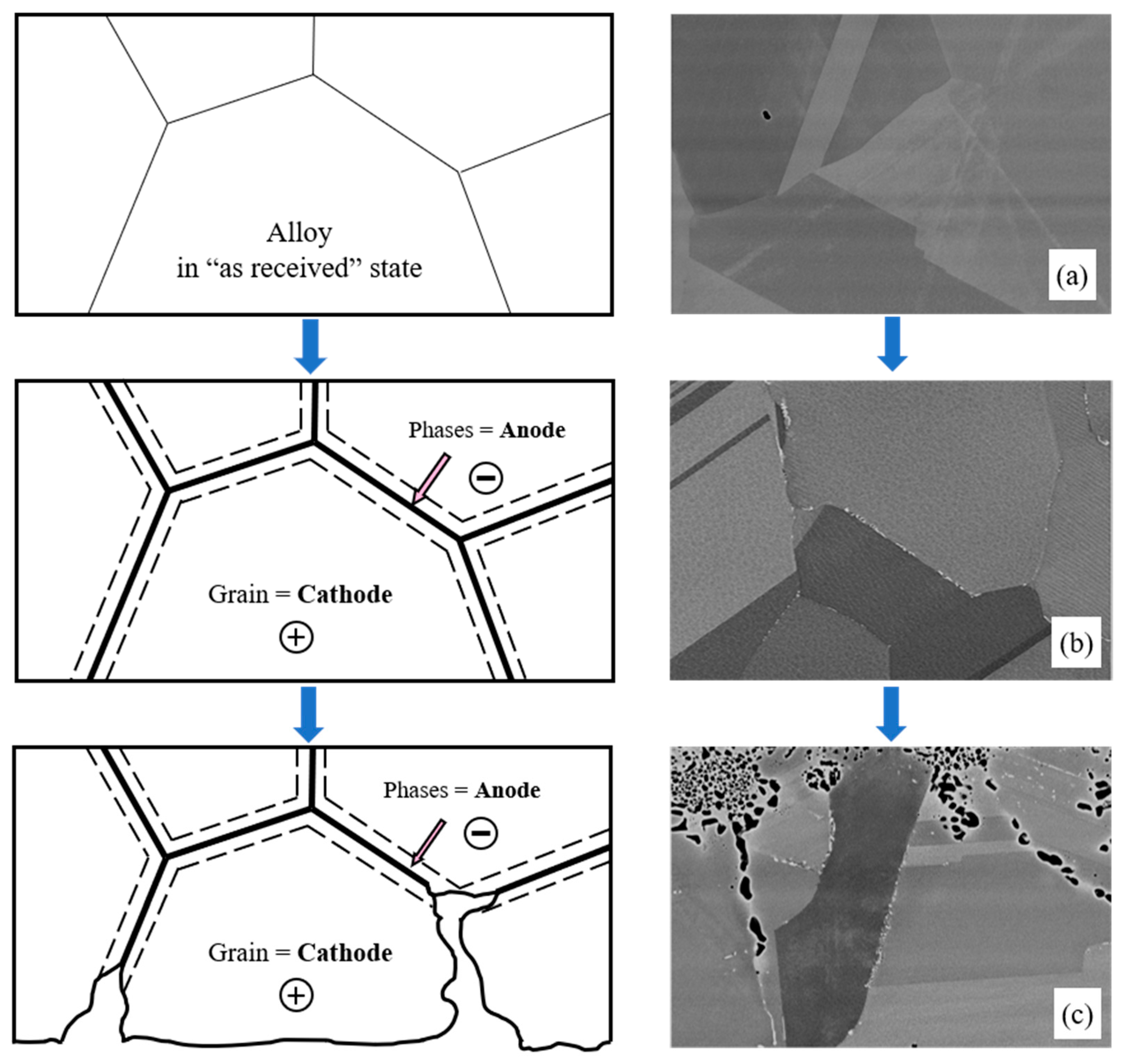
Under the experimental conditions, the best corrosion resistance was exhibited by electropositive metals like nickel and molybdenum; the most electronegative metals were chromium, zirconium, and iron. Thus, it can be expected that the formation of excess phases enriched in chromium will be accompanied by their intense destruction, since they will act as microanodes in the microgalvanic system (Figure 11). An opposite phenomenon can also be expected. Enrichment of excess phases in molybdenum and nickel will contribute to the formation of microcathodes. This process does not lead to intergranular corrosion; however, in some cases IGC may develop due to selective dissolution of depleted zones from which molybdenum and nickel have diffused into the excess phases. These zones will be depleted in the most electropositive metals, and they will also have an increased concentration of defects. This will provoke the formation of a microgalvanic system in which the alloy’s grain and excess microphase will act as microcathodes, and the depleted zone will play a role of a microanode. Such behavior (formation of microcathodes) was observed in the present study for the Hastelloy® B-3® alloy and will be considered in more detail later.
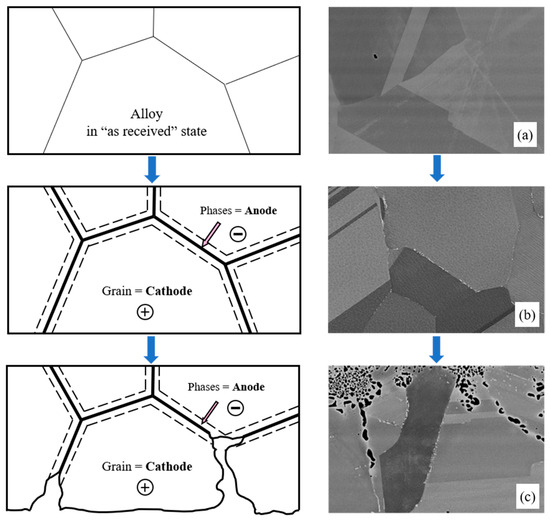
Figure 11.
Schematic representation of the development of corrosion processes with the formation of microanodes at grain boundaries: (a) Microstructure of KhN62M-VI in its ‘as received’ state; (b) Microstructure of KhN62M-VI after exposure at 750 °C for 100 h; (c) Microstructure of KhN62M-VI after corrosion in FLiNaK + UF4 at 750 °C for 100 h.
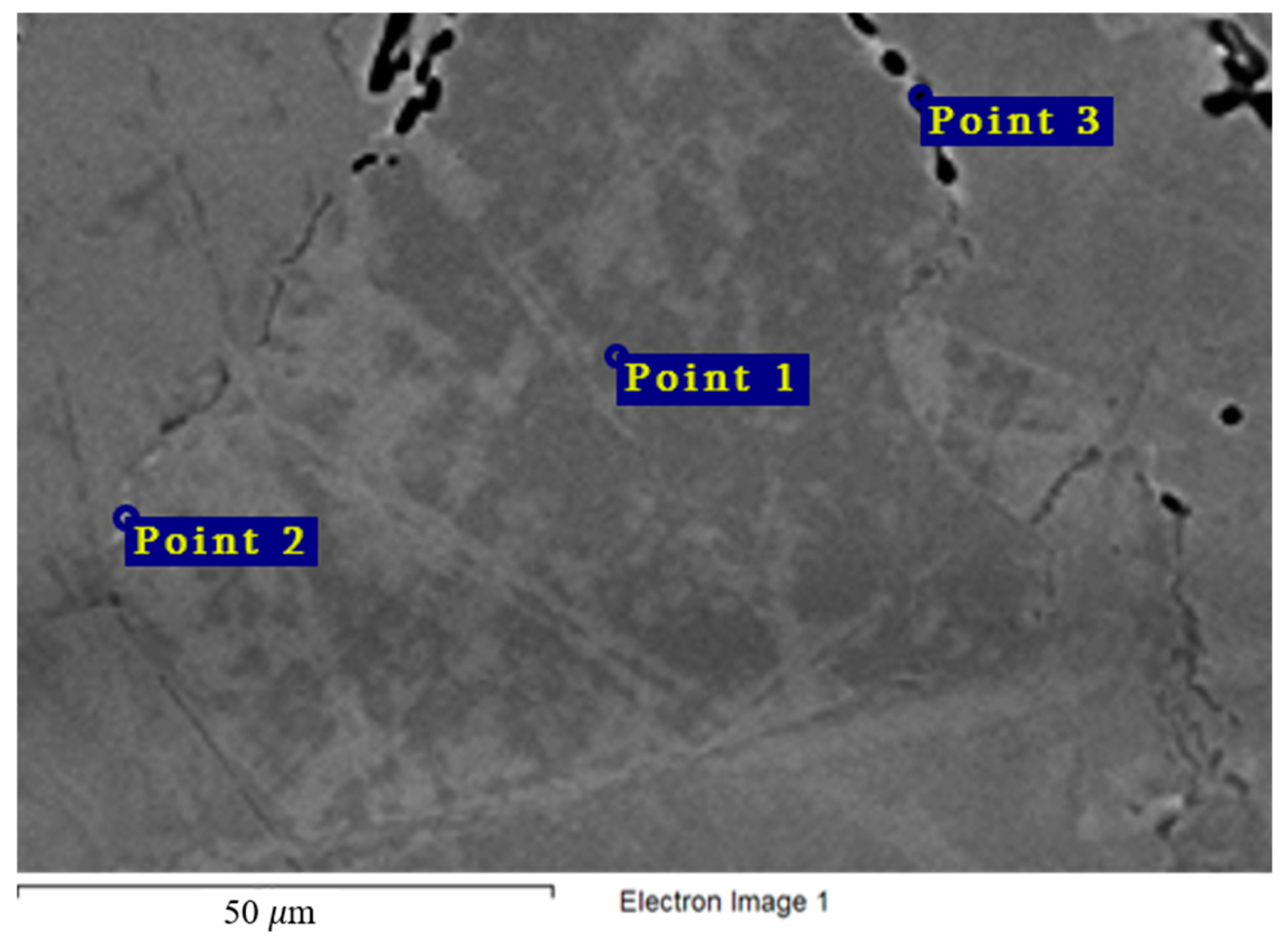
Figure 12 and Table 6 show the chemical composition of secondary phases (Point 2) in the Hastelloy® G-35® alloy and grain composition (Point 1), which corresponds to the content of main components in the bulk of the material. Excess phases in this case are significantly enriched in chromium, which points to the anodic nature of these microphases. Figure 4 shows the nature of the destruction of Hastelloy® G-35® alloy samples after 100 h of contact with FLiNaK and FLiNaK + UF4 melts. The alloy samples experienced pronounced intercrystalline damage, especially at 750 °C, which indicates the localization of corrosion processes along grain boundaries. The composition of the resulting secondary phases suggests that these phases acted as microanodes. The results of microanalysis in the destroyed grain boundary (Point 3) indicate significant chromium depletion in comparison to the bulk of the material, thus confirming the conclusion about selective dissolution of chromium-enriched secondary phases, i.e., microanodes, upon the contact with molten salt. It should also be noted that the total sum of the elements determined in the crack zone (i.e., point 3 in Figure 12) was below 100%. This was caused by the mounting resin penetrating the crack and filling the damaged zone, and thus adding non-metallic elements to the total count of the analysis. Similar deviation from 100% was observed in all subsequent samples, where damaged zones were analyzed.

Figure 12.
Regions of X-ray microanalysis of the microstructure of the Hastelloy® G-35® alloy after corrosion in FLiNaK + UF4 at 750 °C.
Table 6.
Results of X-ray microanalysis at points 1, 2, and 3 of the Hastelloy® G-35® alloy sample after corrosion in molten fluoride systems.
Similar observations were made for the VDM® Alloy 59 and KhN62M-VI alloys (Table 7 and Table 8, Figure 13 and Figure 14). Excess phases (Point 2) were significantly enriched in chromium, and localization of corrosion processes along the grain boundaries was observed for all samples (Figure 5 and Figure 6). The composition of the secondary phases indicates that these phases acted as microanodes.
Table 7.
Results of X-ray microanalysis of points 1, 2, and 3 of the VDM® Alloy 59 sample after corrosion in molten fluoride systems.
Table 8.
Results of X-ray microanalysis of points 1, 2, and 3 of the KhN62M-VI alloy sample after corrosion in molten fluoride systems.
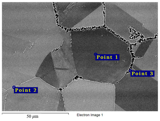
Figure 13.
Regions of X-ray microanalysis of the microstructure of the VDM® Alloy 59 alloy after corrosion in FLiNaK + UF4 at 750 °C.
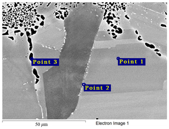
Figure 14.
Regions of X-ray microanalysis of the microstructure of the KhN62M-VI alloy after corrosion in FLiNaK + UF4 at 750 °C.
The chemical composition of the secondary phases and grains of the Hastelloy® B-3® alloy are shown in Figure 15 and Table 9. In this case, the excess phases were enriched in molybdenum and depleted in chromium and iron; moreover, the phases were distributed separately, without forming a continuous network along the grain boundaries. It is likely that the secondary phases formed during high-temperature exposure of the Hastelloy® B-3® alloy would act as microcathodes is the alloy were brought in contact with the electrolyte. The results showed that this alloy did not experience intercrystalline destruction; the corrosion occurred within the surface layer. However, pitting-type surface degradation suggested that, in the case of the Hastelloy® B-3® alloy, the corrosion process can also be localized (Figure 7 and Figure 8). This may result from separation of the excess phases and formation of areas depleted in electropositive elements in the alloy’s grain bulk.
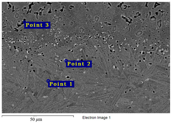
Figure 15.
Regions of X-ray microanalysis of the microstructure of the Hastelloy® B-3® alloy after corrosion in FLiNaK + UF4 at 750 °C.
Table 9.
Results of X-ray microanalysis of points 1, 2, and 3 of the Hastelloy® B-3®alloy sample after corrosion in molten fluoride systems.
Therefore, the experimental data lead to a conclusion that, in the course of formation of excess phases enriched with the most electropositive elements, such zones will act as microcathodes, and IGC will be inhibited. During enrichment of excess phases with the most electronegative components, these phases act as microanodes and, as a result, IGC develops on the contact surface with salt melts.
Thus, on the basis of the corrosion test results, an important factor affecting the corrosion resistance of materials was determined—phase instability or structural changes in materials with the fcc solid solution structure under the influence of high temperatures. Analysis of the chemical composition of the secondary phases formed in materials of various classes allowed possible mechanisms of the influence of excess phases on the corrosion resistance of nickel-based alloys in molten halides to be proposed. It was found that the most dangerous type of excess phase is phases playing the role of microanodes, since they provoke intensification of intercrystalline destruction along grain boundaries.
4. Conclusions
A series of 100 h corrosion tests of various nickel-based alloys (Hastelloy® G-35®, VDM® Alloy 59, KhN62M–VI, Hastelloy®B-3®) in FLiNaK and FLiNaK + UF4 melts was performed at 550, 650, and 750 °C. Corrosion indicators such as corrosion rates, depths of corrosion, and k-parameters were determined based on comprehensive analysis.
The key issue of nickel-based alloy corrosion in molten halides is discussed based on the obtained data. It was shown that the presence of oxidizer in the melt, namely UF4, led to a decrease in material corrosion resistance. Increasing the temperature of the tests, as well as the chromium content in Ni-Cr-Mo alloys, also accelerated corrosion processes. It was demonstrated that a decrease of corrosion resistance with chromium content in nickel-based materials was associated with selective etching of more negative components from the alloy. Increasing corrosion rates with temperature, on the one hand is explained by the Arrhenius law, and on the other hand is caused by phase changes due to thermodynamic instability of Ni-based fcc solid solution that can affect both the corrosion rate and the mechanism of material degradation.
The influence of microstructural changes in the studied alloys on the mechanism of their corrosion in molten salts is discussed in detail. It was established that the formation of anodic excess chain-type phases (enriched by electronegative components) is the most dangerous case when the material is held in contact with an electrolyte at high temperatures, and in particular with a salt melt, because these secondary phases can provoke intergranular corrosion.
It should be understood that the presented data and proposed mechanisms concern short-time ampoule corrosion tests. However, this type of express analysis combining corrosion tests and microstructure investigations enabled selection of the most promising materials from a variety of steels and alloys. During long-term thermal exposure, the microstructure of the alloys can change further. Dynamic conditions also can have an effect on corrosion processes. Therefore, long-term dynamic tests should be carried out after preliminary selection of prospective candidate materials on the basis of short-term investigations to unambiguously establish the expected service life of the material and the characteristic corrosion mechanism for each specific alloy.
Author Contributions
Conceptualization, I.B.P. and V.A.V.; methodology, A.V.A.; software, R.R.A. and A.I.T., validation, R.R.A. and A.V.A.; formal analysis, I.B.P.; data curation, I.B.P.; writing—original draft preparation, A.V.A.; writing—review and editing, I.B.P. and V.A.V.; visualization, A.I.T.; supervision, V.A.V. and I.B.P.; project administration, I.B.P.; funding acquisition, I.B.P. All authors have read and agreed to the published version of the manuscript.
Funding
Research funding from the Ministry of Science and Higher Education of the Russian Federation (Ural Federal University Program of Development within the Priority-2030 Program) is gratefully acknowledged.
Institutional Review Board Statement
Not applicable.
Informed Consent Statement
Not applicable.
Data Availability Statement
The original contributions presented in the study are included in the article; further inquiries can be directed to the corresponding author.
Conflicts of Interest
The authors declare no conflicts of interest.
Abbreviations
The following abbreviations are used in this manuscript:
| CSP | Concentrated solar systems |
| ORNL | Oak Ridge National Laboratory |
| MCR | Molten salt reactors |
| LRO | Long-range ordered |
| HTC | High-temperature creep |
| IGC | Intergranular corrosion |
| TCP | Topologically close-packed |
| GM | Gravimetric method |
| ChM | Chemical method |
| IGSC | Intergranular stress corrosion |
References
- Tosi, M.P. Molten Salts: Fundamentals. In Molten Salts: From Fundamentals to Applications; Gaune-Escard, M., Ed.; Springer: Dordrecht, The Netherlands, 2002; Volume 52, pp. 1–22. [Google Scholar] [CrossRef]
- Lantelme, F.; Groult, H. Molten Salts Chemistry; Elsevier: Amsterdam, The Netherlands, 2013; pp. 1–573. [Google Scholar] [CrossRef]
- Gaune-Escard, M. Molten Salts Chemistry and Technology; John Wiley and Sons Inc.: Hoboken, NJ, USA, 2014; pp. 1–632. [Google Scholar] [CrossRef]
- Dolan, T.; Pazsit, I.; Rykhlevskii, A.; Yoshioka, R. Molten Salts Reactors and Thorium Energy, 2nd ed.; Elsevier: Amsterdam, The Netherlands, 2023; pp. 1–815. [Google Scholar]
- Moriyama, H.; Sagara, A.; Tanaka, S.; Moir, R.W.; Sze, D.K. Molten salts in fusion nuclear technology. Fusion Eng. Des. 1998, 39–40, 627–637. [Google Scholar] [CrossRef]
- Ladkany, S.; Culbreth, W.; Loyd, N. Molten salts and applications I: Molten salt history, types, thermodynamic and physical properties, and cost. J. Energy Eng. 2018, 12, 507–516. [Google Scholar] [CrossRef]
- Roper, R.; Harkema, M.; Sabharwall, P.; Riddle, C.; Chisholm, B.; Day, B.; Marotta, P. Molten salt for advanced energy applications: A review. Ann. Nucl. Energy 2021, 169, 108924. [Google Scholar] [CrossRef]
- Le Brun, C. Molten salts and nuclear energy production. J. Nucl. Mater. 2007, 360, 1–5. [Google Scholar] [CrossRef]
- Murty, K.; Charit, I. Structural materials for Gen-IV nuclear reactors: Challenges and opportunities. J. Nucl. Mater. 2008, 383, 189–195. [Google Scholar] [CrossRef]
- Uhlíř, J. Chemistry and technology of Molten Salt Reactors—Hhistory and perspectives. J. Nucl. Mater. 2007, 360, 6–11. [Google Scholar] [CrossRef]
- Williams, D.F. Assessment of Candidate Molten Salt Coolants for the Advanced High Temperature Reactor, Report. 2006. Available online: https://digital.library.unt.edu/ark:/67531/metadc873760/ (accessed on 13 April 2025).
- Bhatnagar, P.; Siddiqui, S.; Sreedhar, I.; Parameshwaran, R. Molten salts: Potential candidates for thermal energy storage applications. Int. J. Energy Res. 2022, 46, 17755–17785. [Google Scholar] [CrossRef]
- Chen, H.; Ngoc Cong, T.; Yang, W.; Tan, C.; Li, Y.; Ding, Y. Progress in electrical energy storage system: A critical review. Prog. Nat. Sci. 2009, 19, 291–312. [Google Scholar] [CrossRef]
- Pardo, P.; Deydier, A.; Anxionnaz-Minvielle, Z.; Rougé, S.; Cabassud, M.; Cognet, P. A review on high temperature thermochemical heat energy storage. Renew. Sustain. Energy 2014, 32, 591–610. [Google Scholar] [CrossRef]
- Bettis, E.S.; Schroeder, R.W.; Cristy, G.A.; Savage, H.W.; Affel, R.G.; Hemphill, L.F. The aircraft reactor experiment–design and construction. Nucl. Sci. Eng. 1957, 2, 804–825. [Google Scholar] [CrossRef]
- World Nuclear Association. Molten Salt Reactors: Current and Future Generation. Available online: https://world-nuclear.org/information-library/current-and-future-generation/molten-salt-reactors (accessed on 7 March 2025).
- International Atomic Energy Agency. Status of Molten Salt Reactor Technology; Technical Reports Series No. 489; IAEA: Vienna, Austria, 2023; Available online: https://www-pub.iaea.org/MTCD/Publications/PDF/STI-DOC-010-489_web.pdf (accessed on 3 March 2025).
- Bahri, C.N.A.C.Z.; Al-Areqi, W.M.; Ruf, M.F.M.; Majid, A.A. Characteristic of molten fluoride salt system LiF-BeF2 (FLiBe) and LiF-NaF-KF (FLiNaK) as coolant and fuel carrier in molten salt reactor (MSR). AIP Conf. Proc. 2017, 1799, 040008. [Google Scholar] [CrossRef]
- Lizin, A.A.; Tomilin, S.V.; Gnevashov, O.E.; Gazizov, R.K.; Osipenko, A.G.; Kormilitsyn, M.V.; Baranov, A.A.; Zaharova, L.V.; Naumov, V.S.; Ponomarev, L.I. PuF3, AmF3, CeF3, and NdF3 Solubility in a LiF–NaF–KF Melt. At. Energy 2013, 115, 11–17. [Google Scholar] [CrossRef]
- Lizin, A.A.; Tomilin, S.V.; Gnevashov, O.E.; Gazizov, R.K.; Osipenko, A.G.; Kormilitsyn, M.V.; Nezgovorov, N.Y.; Naumov, V.S.; Ponomarev, L.I. UF4, ThF4 Solubility in a LiF–NaF–KF Melt. At. Energy 2013, 115, 22–25. [Google Scholar] [CrossRef]
- Ponomarev, L.; Seregin, M.; Parshin, A.; Melnikov, S.; Mikhalichenko, A.; Zagorets, L.; Manuylov, R.; Rzheutskii, A. Fuel Salt for a Molten-Salt Reactor. At. Energy 2013, 115, 5–10. [Google Scholar] [CrossRef]
- Guo, S.; Zhang, J.; Wu, W.; Zhou, W. Corrosion in the molten fluoride and chloride salts and materials development for nuclear applications. Prog. Mater. Sci. 2018, 97, 448–487. [Google Scholar] [CrossRef]
- Ye, X.-X.; Ai, H.; Guo, Z.; Huang, H.; Jiang, L.; Wang, J.; Li, Z.; Zhou, X. The high-temperature corrosion of Hastelloy N alloy (UNS N10003) in molten fluoride salts analyzed by STXM, XRD, SEM, EPMA, TEM/EDS. Corros. Sci. 2016, 106, 249–259. [Google Scholar] [CrossRef]
- Xu, H.; Liu, Q.; Leng, B.; Zhang, W.; Ye, X.-X.; Han, F.; Li, X.; Liu, R.; Wang, J. Non-uniform corrosion of UNS N10003 alloy induced by trace SO42− in molten FLiNaK salt. Corros. Sci. 2021, 192, 109802. [Google Scholar] [CrossRef]
- Ai, H.; Chen, Y.; Yang, X.; Sun, H.; Su, X.; Yan, L.; Huang, W.; Gong, Y. Intergranular corrosion of 316H stainless steel induced by SO42− ions in MgCl2–KCl–NaCl molten salt. Sol. Energy Mater. Sol. Cells. 2024, 271, 112851. [Google Scholar] [CrossRef]
- Sellers, R.S.; Cheng, W.J.; Kelleher, B.C.; Anderson, M.H.; Sridharan, K.; Wang, C.J.; Allen, T.R. Corrosion of 316L Stainless Steel Alloy and Hastelloy-N Superalloy in Molten Eutectic LiF-NaF-KF Salt and Interaction with Graphite. Nucl. Technol. 2014, 188, 192–199. [Google Scholar] [CrossRef]
- Olson, L.C.; Ambrosek, J.W.; Sridharan, K.; Anderson, M.H.; Allen, T.R. Materials corrosion in molten LiF–NaF–KF salt. J. Fluor. Chem. 2009, 130, 67–73. [Google Scholar] [CrossRef]
- Dai, Q.; Ye, X.-X.; Ai, H.; Chen, S.; Jiang, L.; Liang, J.; Yu, K.; Leng, B.; Li, Z.; Zhou, X. Corrosion of Incoloy 800H alloys with nickel cladding in FLiNaK salts at 850 °C. Corros. Sci. 2018, 133, 349–357. [Google Scholar] [CrossRef]
- Ignat’ev, V.V.; Surenkov, A.I.; Gnidoi, I.P.; Fedulov, V.I.; Uglov, V.S.; Panov, A.V.; Sagaradze, V.V.; Subbotin, V.G.; Toropov, A.D.; Afonichkin, V.K.; et al. Investigation of the corrosion resistance of nickel-based alloy in fluoride melts. At. Energy 2006, 101, 730–738. [Google Scholar] [CrossRef]
- Ignatiev, V.; Surenkov, A. Alloys compatibility in molten salt fluorides: Kurchatov Institute related experience. J. Nucl. Mater. 2013, 441, 592–603. [Google Scholar] [CrossRef]
- Ignatiev, V. Calculation of Safety Related Parameters for Na, Li, Be/F MOSART Concept. Consultancy on “Studies of Innovative Reactor Technology Options for Effective Incineration of Radioactive Waste”; International Atomic Energy Agency: Vienna, Austria, 2006; pp. 125–147. Available online: https://inis.iaea.org/records/64d8b-hfq45 (accessed on 15 April 2025).
- Ignatiev, V. Critical Issues of Nuclear Energy Systems Employing Molten Salt Fluorides’. In Proceedings of the ACSEPT International Workshop, Lisbon, Portugal, 31 March–2 April 2010; p. 20. Available online: https://inis.iaea.org/records/j2d16-kc140 (accessed on 17 April 2025).
- Zheng, G.; Kelleher, B.; Cao, G.; Anderson, M.; Allen, T.; Sridharan, K. Corrosion of 316 stainless steel in high temperature molten Li2BeF4 (FLiBe) salt. J. Nucl. Mater. 2015, 461, 143–150. [Google Scholar] [CrossRef]
- Ouyang, F.; Chang, C.; You, B.; Yeh, T.; Kai, J. Effect of moisture on corrosion of Ni-based alloys in molten alkali fluoride FLiNaK salt environments. J. Nucl. Mater. 2013, 437, 201–207. [Google Scholar] [CrossRef]
- Ouyang, F.; Chang, C.; Kai, J. Long-term corrosion behaviors of Hastelloy-N and Hastelloy-B3 in moisture-containing molten FLiNaK salt environments. J. Nucl. Mater. 2014, 446, 81–89. [Google Scholar] [CrossRef]
- Wang, Y.; Wang, Q.; Liu, H.; Zeng, C. Effects of the oxidants H2O and CrF3 on the corrosion of pure metals in molten (Li,Na,K)F. Corros Sci. 2016, 103, 268–282. [Google Scholar] [CrossRef]
- Wang, Y.; Liu, H.; Yu, G.; Hou, J.; Zeng, C. Electrochemical study of the corrosion of a Ni-based alloy GH3535 in molten (Li,Na,K)F at 700 °C. J. Fluor. Chem. 2015, 178, 14–22. [Google Scholar] [CrossRef]
- Patel, N.; Pavlík, V.; Boča, M. High-Temperature Corrosion Behavior of Superalloys in Molten Salts—A Review. Crit. Rev. Solid State Mater. Sci. 2016, 42, 83–97. [Google Scholar] [CrossRef]
- Polovov, I.B.; Abramov, A.V.; Gibadullina, A.F.; Alimgulov, R.R.; Karpov, V.V.; Zhilyakov, A.Y.; Khotinov, V.A.; Belikov, S.V. The effect of microstructure on the corrosion resistance of VDM® alloy C-4 in molten salts. J. Alloys Compd. 2019, 810, 151758. [Google Scholar] [CrossRef]
- Tawancy, H.M.; Alhems, L.M. Correlation Between the State of Atomic Order in Selected (Ni–Mo–Cr)-Based Alloys and Their Corrosion Resistance. Metallogr. Microstruct. Anal. 2018, 7, 746–754. [Google Scholar] [CrossRef]
- Teng, F.; Copeland-Johnson, T.M.; Tucker, J.D.; Cao, G. Accelerated corrosion of Ni-based alloys in molten chloride salts, due to Ni2Cr phase formation. Materialia 2023, 31, 101875. [Google Scholar] [CrossRef]
- Maric, M.; Muránsky, O.; Karatchevtseva, I.; Ungár, T.; Hester, J.; Studer, A.; Scales, N.; Ribárik, G.; Primig, S.; Hill, M.R. The effect of cold-rolling on the microstructure and corrosion behaviour of 316L alloy in FLiNaK molten salt. Corros. Sci. 2018, 142, 133–144. [Google Scholar] [CrossRef]
- Muránsky, O.; Karatchevtseva, I.; Danon, A.E.; Holmes, R.; Huai, P.; Zhang, Z. Impact of dislocations and dislocation substructures on molten salt corrosion of alloys under plasticity-imparting conditions. Corros. Sci. 2020, 176, 108915. [Google Scholar] [CrossRef]
- Abramov, A.V.; Polovov, I.B.; Volkovich, V.A.; Rebrin, O.I. Corrosion of Austenitic Stainless Steels in Chloride Melts. In Molten Salts Chemistry and Technology; Gaune-Escard, M., Haarberg, G.M., Eds.; John Wiley & Sons Inc.: Hoboken, NJ, USA, 2014; pp. 427–448. [Google Scholar] [CrossRef]
- Polovov, I.B.; Abramov, A.V.; Dedov, K.V.; Karpov, V.V.; Zhilyakov, A.Y.; Gibadullina, A.F.; Belikov, S.V.; Volkovich, V.A.; Rebrin, O.I. Corrosion of austenitic steels and their components in uranium-containing chloride melts. ECS Trans. 2017, 77, 847–855. [Google Scholar] [CrossRef]
- Polovov, I.B.; Abramov, A.V.; Karpov, V.V.; Gibadullina, A.F.; Zhilyakov, A.Y.; Dedov, K.V.; Belikov, S.V.; Shak, A.V.; Volkovich, V.A.; Rebrin, O.I. Corrosion of nickel-based superalloys in molten chloroaluminates. ECS Trans. 2017, 77, 753–766. [Google Scholar] [CrossRef]
- Polovov, I.B.; Abramov, A.V.; Alimgulov, R.R.; Zolotarev, D.A.; Trubcheninova, A.I.; Gibadullina, A.F.; Volkovich, V.A.; Zhilyakov, A.Y.; Khotinov, V.A.; Belikov, S.V. Corrosion of metallic materials in the molten FLiNaK. ECS Trans. 2020, 98, 453–462. [Google Scholar] [CrossRef]
- Polovov, I.B.; Abramov, A.V.; Alimgulov, R.R.; Zolotarev, D.A.; Trubcheninova, A.I.; Gibadullina, A.F.; Volkovich, V.A.; Zhilyakov, A.Y.; Khotinov, V.A.; Belikov, S.V. Corrosion of Ceramic and Carbon-Based Materials in FLiNaK. ECS Trans. 2020, 98, 373–381. [Google Scholar] [CrossRef]
- Trubcheninova, A.I.; Abramov, A.V.; Alimgulov, R.R.; Polovov, I.B.; Zolotarev, D.A.; Markelov, V.I.; Gaeva, S.P.; Rebrin, O.I. Quantitative assessment of the intensity of intercrystalline destruction and the degree of uniformity of corrosion. Russ. Metall. 2024, 4, 990–998. [Google Scholar] [CrossRef]
- Patent No. 2672647 C1 Russian Federation, MPC C22C 19/05. Corrosion Resistant Alloy: No. 2017127607: Applied. 01.08.2017: Published 16.11.2018; Aseev, M. A., Belikov, S.V., Dedov, K.V. [and others]; Applicant Joint Stock Company Chepetsky Mechanical Plant.-EDN SODAMK. Available online: https://www.elibrary.ru/item.asp?id=38159491&ysclid=m8guz2qpv803317584 (accessed on 15 April 2025).
- Davis, J.R. Nickel, Cobalt, and Their Alloys; ASM International: Novelty, OH, USA, 2000; pp. 1–425. [Google Scholar]
- Tawancy, H.M. Long-term ageing characteristics of some commercial nickel-chromium-molybdenum alloys. J. Mater. Sci. 1981, 16, 2883–2889. [Google Scholar] [CrossRef]
- Gozlan, E.; Bamberger, M.; Dirnfeld, S.F.; Prinz, B.; Klodt, J. Topologically close-packed precipitations and phase diagrams of Ni-Mo-Cr and Ni-Mo-Fe and of Ni-Mo-Fe with constant additions of chromium. Mater. Sci. Eng. 1991, 141, 85–95. [Google Scholar] [CrossRef]
- Tawancy, H.M. Effect of Cr on the ordering behavior and ductility of an Ni-Ni4Mo alloy. Metall. Mat. A 1992, 23, 1829–1833. [Google Scholar] [CrossRef]
- Turchi, P.E.A.; Kaufman, L.; Liu, Z.-K. Modeling of Ni–Cr–Mo based alloys: Part I—Phase stability. Calphad 2006, 30, 70–87. [Google Scholar] [CrossRef]
- Nicoletti, E.S.; Darwish, F.A.; Solórzano, G. On the development of nano and microscale precipitates upon isothermal aging of nickel base superalloy 59. Mater. Sci. Eng. B 2004, 112, 214–222. [Google Scholar] [CrossRef]
- Belikov, S.V.; Zhilyakov, A.Y.; Popov, A.A.; Karabanalov, M.S.; Polovov, I.B. Special Features of Formation of Excess Phases During Aging of Corrosion-Resistant High-Alloy Austenitic Alloys Based on Fe and Ni. Met. Sci. Heat Treat. 2015, 56, 637–645. [Google Scholar] [CrossRef]
- Tawancy, H.M. On the Precipitation of Intermetallic Compounds in Selected Solid-Solution-Strengthened Ni-Base Alloys and Their Effects on Mechanical Properties. Metallogr. Microstruct. Anal. 2017, 6, 200–215. [Google Scholar] [CrossRef]
- Pyrin, D.V.; Chuquimarca, P.K.; Beltyukov, E.A.; Raschektaeva, D.V.; Zhilyakov, A.Y.; Belikov, S.V. Effect of Structural-Phase State on Young’s Modulus of a Nickel Corrosion-Resistant Alloy. Russ. Phys. J. 2024, 67, 1302–1308. [Google Scholar] [CrossRef]
- Jebaraj, J.J.; Morrison, D.J.; Suni, I.I. Hydrogen Diffusion in Alloy 686 (UNS N06686) and Alloy 59 (UNS N06059). Corrosion 2015, 71, 376–388. [Google Scholar] [CrossRef]
- Tawancy, H.M. Correlation between disorder-order transformations in a Ni-based alloy and its mechanical properties. Mater. Eng. Res. 2018, 719, 93–103. [Google Scholar] [CrossRef]
- Hübner, P.; Behrens, R.; Alves, H.; Niespodziany, D.; Sarrat, O.; König, J. New Experiences with Explosion Clad Alloys UNS N06058 and UNS N06059. In Proceeding of the AMPP Annual Conference + Expo, San Antonio, TX, USA, 6–10 March 2022. [Google Scholar]
- Ignatiev, V.; Surenkov, A. Corrosion Phenomena Induced by Molten Salts in Generation IV Nuclear Reactors. In Structural Materials for Generation IV Nuclear Reactors; Yvon, P., Ed.; Woodhead Publishing: Cambridge, UK, 2017; pp. 153–189. [Google Scholar] [CrossRef]
- Falconer, C.; Elbakhshwan, M.; Doniger, W.; Weinstein, M.; Sridharan, K.; Couet, A. Activity gradient driven mass transport in molten fluoride salt medium. npj Mater. Degrad. 2022, 6, 29. [Google Scholar] [CrossRef]
- Sankar, K.M.; Singh, P.M. Effect of metal fluorides on the corrosion of structural materials in molten LiF-NaF-KF. Corros. Sci. 2023, 213, 110977. [Google Scholar] [CrossRef]
- Koger, J.W. Chromium Depletion and Void Formation in Fe—Ni—Cr Alloys During Molten Salt Corrosion and Related Processes. In Advances in Corrosion Science and Technology; Fontana, M.G., Staehle, R.W., Eds.; Springer: Boston, MA, USA, 1974. [Google Scholar] [CrossRef]
- Ai, H.; Ye, X.-X.; Jiang, L.; Leng, B.; Shen, M.; Li, Z.; Jia, Y.; Wang, J.-Q.; Zhou, X.; Xie, Y.; et al. On the possibility of severe corrosion of a Ni-W-Cr alloy in fluoride molten salts at high temperature. Corros. Sci. 2019, 149, 218–225. [Google Scholar] [CrossRef]


Disclaimer/Publisher’s Note: The statements, opinions and data contained in all publications are solely those of the individual author(s) and contributor(s) and not of MDPI and/or the editor(s). MDPI and/or the editor(s) disclaim responsibility for any injury to people or property resulting from any ideas, methods, instructions or products referred to in the content. |
© 2025 by the authors. Licensee MDPI, Basel, Switzerland. This article is an open access article distributed under the terms and conditions of the Creative Commons Attribution (CC BY) license (https://creativecommons.org/licenses/by/4.0/).