Article

Novel Research on a Finite-Difference Time-Domain Acceleration Algorithm Based on Distributed Cluster Graphic Process Units

1
School of Physics, Xidian University, Xi’an 710071, China
2
Key Laboratory of Optoelectronic Information Perception in Complex Environment, Ministry of Education, Xi’an 710071, China
*
Author to whom correspondence should be addressed.
Appl. Sci. 2025, 15(9), 4834; https://doi.org/10.3390/app15094834 (registering DOI)
Submission received: 24 March 2025 / Revised: 23 April 2025 / Accepted: 24 April 2025 / Published: 27 April 2025
(This article belongs to the Section Electrical, Electronics and Communications Engineering)

Abstract

:
In computational electromagnetics, the finite-difference time-domain (FDTD) method is recognized for its volumetric discretization approach. However, it can be computationally demanding when addressing large-scale electromagnetic problems. This paper introduces a novel approach by incorporating Graphic Process Units (GPUs) into an FDTD algorithm. It leverages the Compute Unified Device Architecture (CUDA) along with OpenMPI and the NVIDIA Collective Communications Library (NCCL) to establish a parallel scheme for the FDTD algorithm in distributed cluster GPUs. This approach enhances the computational efficiency of the FDTD algorithm by circumventing data relaying by the CPU and the limitations of the PCIe bus. The improved efficiency renders the FDTD algorithm a more practical and efficient solution for real-world electromagnetic problems.

1. Introduction

With the rapid development of computing technology, numerical simulation methods are increasingly being used in computational electromagnetics. As a powerful electromagnetic simulation tool, the finite-difference time-domain (FDTD) method is widely favored for its intuitive, versatile, and flexible nature [1,2,3,4]. However, the FDTD method generally uses structural grids to discretize the problem being solved, which have significant step errors [5]. To reduce errors, the grid size in the FDTD method is generally less than one-twelfth of the wavelength. For some structures, such as holes, slots, and wedges, finer grids are required to ensure a better simulation of geometric shapes. In practical large-scale and complex electromagnetic problems, the target structure, material, etc., are becoming increasingly complex, and the calculated frequency is also increasing, which inevitably leads to a sharp increase in the sizes of computational grids. Due to the limitations of computer hardware resources, the traditional single-machine serial FDTD calculation scheme can no longer meet the actual computational needs. Fortunately, the FDTD method does not require solving matrix equations, which means its computational efficiency can be improved significantly through parallel processing.
An FDTD algorithm exhibits inherent parallelism, allowing for the division of the computational domain into multiple subdomains. By facilitating data exchange solely between adjacent subdomains, this approach achieves the parallelization of the FDTD algorithm while significantly enhancing its computational efficiency. At the hardware level, the parallelization of the FDTD algorithm can generally be divided into two categories: central processing unit (CPU) parallelism and graphics processing unit (GPU) parallelism. A CPU is good at handling sequential and complex computational tasks, and its core count is generally low (typically tens of cores), but each core has a relatively high computational power. To meet the needs of large-scale computing, many CPUs are required for collaborative computing, which is costly. A GPU, on the other hand, is good at parallel processing many simple computational tasks, and it has thousands of cores that can handle multiple threads and tasks simultaneously. With the same computational power, the computational cost of a CPU is much higher than that of a GPU. Therefore, developing GPU-based FDTD algorithms can improve their computational efficiency and applicability significantly and economically.
Nowadays, GPU-based FDTD algorithms are emerging in an endless stream, and the computational power and efficiency of FDTD algorithms are being continuously improved. FDTD algorithms based on a GPU are also widely used in ground-penetrating radar [6], electromagnetic scattering [7], magnetic resonance imaging [8], transmission line calculation [9], and other related fields [10,11]. For different computational requirements, researchers have developed FDTD parallel algorithms based on a single GPU [6,7,12,13], multi-GPUs at one node [9,10,11,14,15,16,17], and multi-GPUs at multi-nodes [18,19,20,21]. In multi-GPU parallel FDTD algorithms, the communication efficiency between the GPUs, especially inter-node GPUs, is critical to the computational efficiency. The existing intra-node GPU communication requires data exchange through a PCIe bus, and inter-node GPU communication requires data forwarding through a CPU. The limitations of the I/O bandwidth and CPU forwarding speed have hindered the improvement of multi-GPU parallel efficiency.
The NVLink communication protocol proposed by NVIDIA provides high-bandwidth, low-latency direct communication between GPUs [22]. Compared to CPU forwarding and PCIe communication, NVLink delivers better performance and efficiency of the data transmission and collaboration between GPUs. Furthermore, NVIDIA has also developed the NVIDIA Collective Communications Library (NCCL) for high-speed data transmission and communication between multiple GPUs [23]. The NCCL performs automatic hardware topology detection, which it then uses in graph search algorithms to identify the communication paths that offer the highest bandwidth and lowest latencies for communication between intra- and inter-node GPUs [24]. Currently, this technology has not been used in FDTD algorithms. Therefore, this paper studies an inter-node multi-GPU FDTD algorithm parallel scheme based on the NCCL technology on the CUDA platform using OpenMPI 4.0.1 for process and computation task allocation. Each GPU is mounted onto a single CPU process, and the GPUs within a node are connected using NVLink. InfiniBand network cards are used to communicate between nodes. The NCCL is used to control GPU communication. Neither CPU forwarding nor a PCIe bus during data exchange is required in the scheme, which significantly improves the parallel efficiency of FDTD algorithms and promotes the broad application of FDTD methods in practical electromagnetic problems.
The structure of this paper is as follows: Section 2 briefly gives the FDTD algorithm. Section 3 provides the 3D FDTD parallel algorithm on the CUDA platform, including the FDTD calculation domain decomposition scheme and data transmission scheme based on the NCCL. Section 4 presents the simulation results and analysis. Finally, Section 5 concludes the paper.

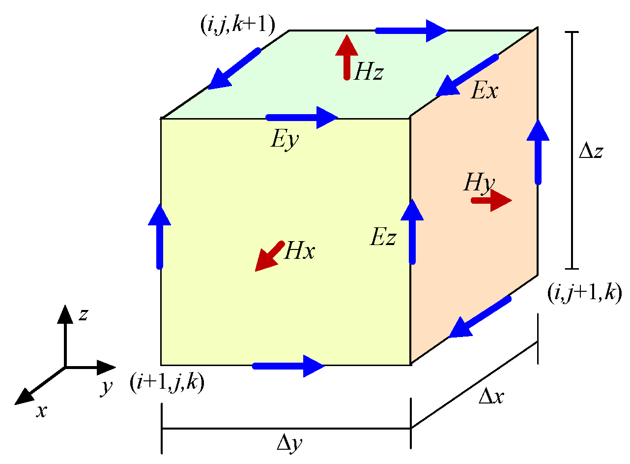
2. The FDTD Algorithm

The FDTD algorithm uses Yee cells to discretize the target, as shown in Figure 1. This algorithm uses center-difference discretization for Maxwell’s curl equation in both time and space, resulting in explicit iterations of the electric and magnetic fields [5].
Taking the x-direction electric field E x as an example, its time iteration formula is
E x n + 1 ( i + 1 2 , j , k ) = C A ( m ) E x n ( i + 1 2 , j , k ) + C B ( m ) [ H z n + 1 2 ( i + 1 2 , j + 1 2 , k ) H z n + 1 2 ( i + 1 2 , j 1 2 , k ) Δ y H y n + 1 2 ( i + 1 2 , j , k + 1 2 ) H y n + 1 2 ( i + 1 2 , j , k 1 2 ) Δ z ]
Among them, ( i + 1 / 2 , j , k ) , ( i + 1 / 2 , j + 1 / 2 , k ) , ( i + 1 / 2 , j 1 / 2 , k ) , ( i + 1 / 2 , j , k + 1 / 2 ) , and ( i + 1 / 2 , j , k 1 / 2 ) are the spatial sampling points; n , n + 1 / 2 , and n + 1 are the temporal sampling points; H y and H z are the magnetic fields in the y-direction and z-direction, respectively; Δ y and Δ z are the spatial grid sizes in the y-direction and z-direction, respectively; and C A m and C B m are the coefficients related to the time step Δ t and medium parameters, and their calculation formulas are as follows:
C A ( m ) = 1 σ ( m ) Δ t 2 ε ( m ) 1 + σ ( m ) Δ t 2 ε ( m ) , C B ( m ) = Δ t ε ( m ) 1 + σ ( m ) Δ t 2 ε ( m )
where ε and σ are the permittivity and conductivity, respectively. Due to the use of an explicit iterative format, the electric field iteration in the FDTD algorithm is only spatially related to the magnetic field at adjacent positions, and the same goes for the magnetic field iteration. No matrix operation is involved in the iteration process, resulting in high computational efficiency. However, due to the use of structural mesh discretization in this method, the fitting to the target is poor. When dealing with electromagnetic problems such as complex structures and large-sized targets, it is necessary to use a large number of grids to discretize the above targets, which results in high computational complexity and a long computation time. To improve the computational efficiency, GPU parallel computing has become an effective solution.

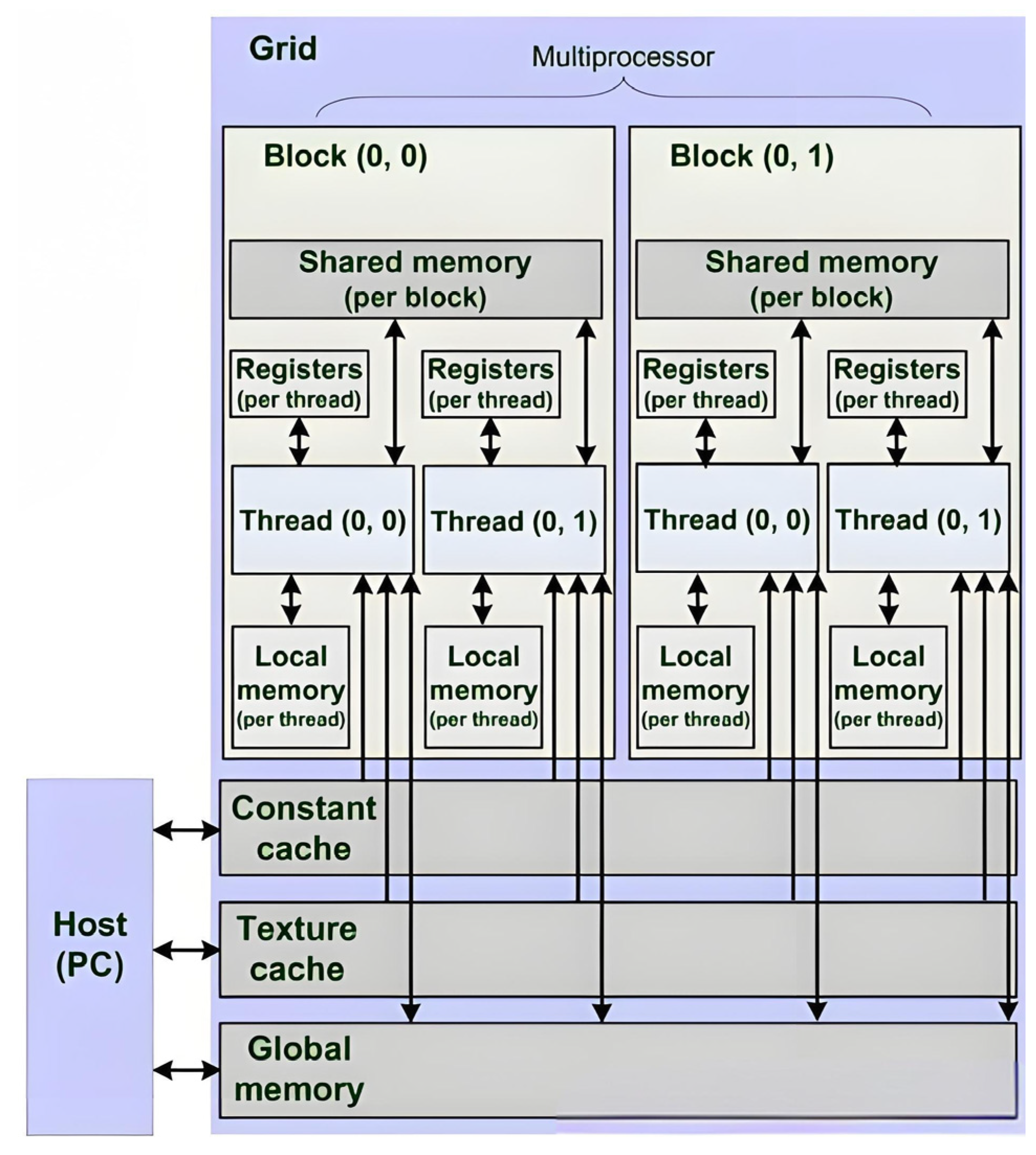
3. Three-Dimensional FDTD Parallel Algorithm on the CUDA Platform

FDTD is computationally intensive, especially for large-scale simulations involving fine spatial grids or long-time iterations. NVIDIA’s CUDA platform enables massive parallelism by leveraging GPU hardware, offering significant speedups compared to CPU-based implementations.
CUDA programming mainly involves two main parts: the host code and device code. The host code runs on the CPU and is responsible for data preparation, task scheduling, and results collection. The device code runs on the GPU and is responsible for executing the actual computing tasks. Developers need to use the CUDA compiler to compile the device code into GPU-executable binary files, and then call these functions in the host code to perform the computing tasks. The CPU and GPU each have independent memory address spaces, including host-side memory and device-side video memory. CUDA’s memory operations are the same as those of general C++ programs. The GPU has a unique graphics memory system, and the operating graphics memory requires calling the memory management functions in CUDA’s API, including opening, releasing, and initializing the graphics memory space, as well as transferring data between the host and device sides. The CUDA parallel computing function running on the GPU is called a kernel. A kernel is not a complete program, but a step in the CUDA program that can be executed in parallel. A complete CUDA program is composed of a series of device-side kernel functions and host-side serial steps, which are executed in the order of the corresponding statements in the program. Figure 2 is a hardware storage architecture diagram of a GPU.
In parallel computing, a reasonable subdomain division scheme and an efficient subdomain communication strategy are the keys to achieving high-efficiency parallel computing. This section will provide the corresponding solutions for the two critical issues mentioned above.

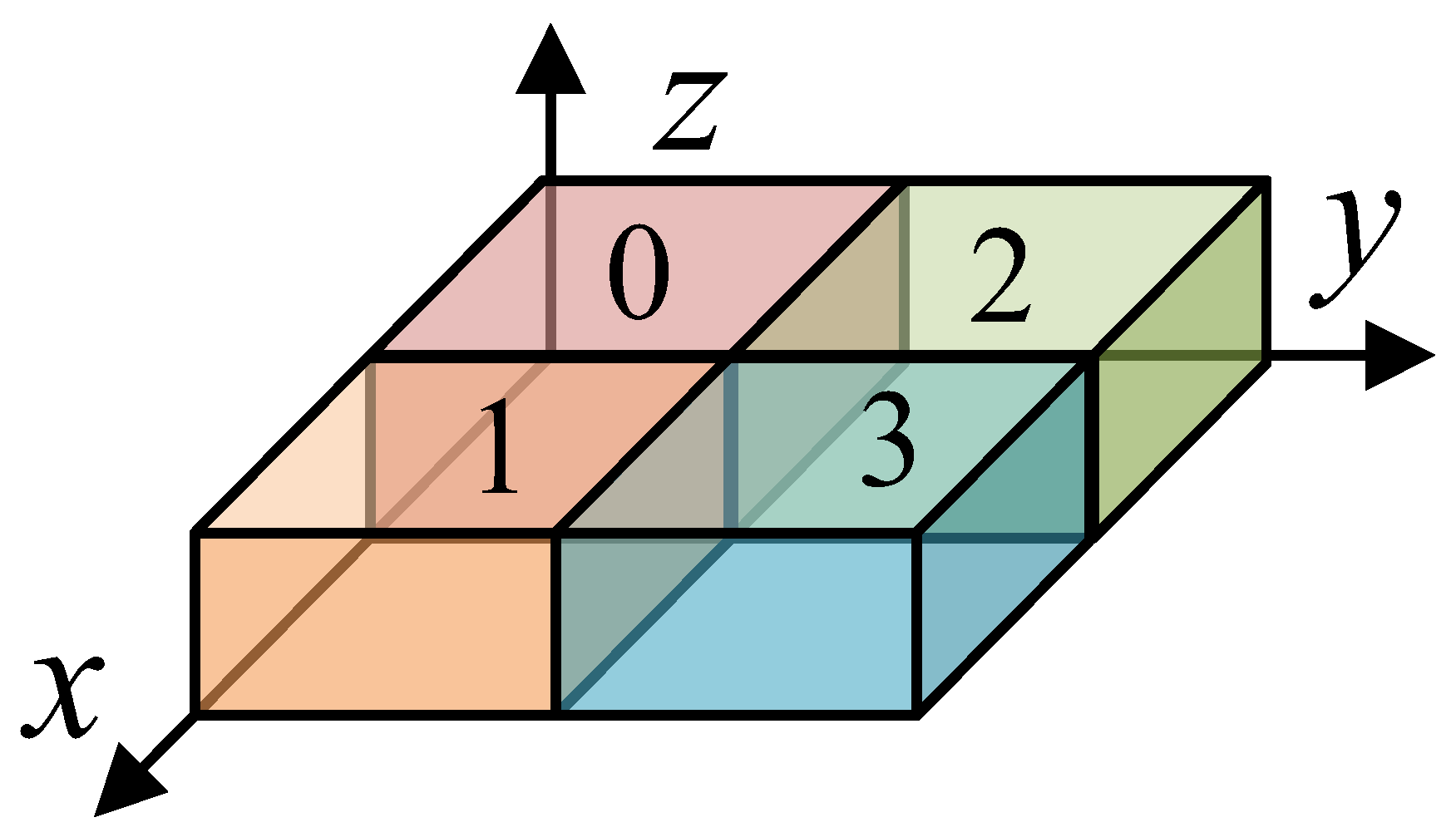
3.1. FDTD Calculation Domain Decomposition Scheme

During the time-marching of an FDTD, the recursion of the electric and magnetic fields requires using the magnetic and electric fields from adjacent subdomains, thus necessitating data exchange at the boundaries between adjacent subdomains. The computational region of an FDTD can be divided into multiple subdomains in one, two, or three dimensions. The subdomain partitioning strategy affects the communication between adjacent processes, further influencing the computational efficiency. Generally, the principle of minimizing the communication volume between subdomains should be followed when partitioning subdomains. For the FDTD algorithm, reducing the cross-sectional area at the subdomain boundary is necessary, ensuring the least amount of communication between the subdomains.
Based on the actual computational requirements and hardware resources, this paper adopts a two-dimensional (along the x- and y-directions) subdomain partitioning scheme for the computational domain. In this case, the data of the yoz cross-section are continuously distributed in the memory, while those of the xoz cross-section are discontinuous. Thus, it is efficient to exchange data between adjacent processes of the yoz cross-section, but the not for the data of the xoz cross-section. When exchanging the data of the xoz cross-section, by creating a temporary array and establishing the mapping relationship between the xoz cross-section and the temporary array, then the communication efficiency can be improved by exchanging the temporary arrays between adjacent processes. Figure 3 shows a schematic diagram of the computational domain cut into four subdomains along the x- and y-directions.
Load balancing is also an important indicator for measuring the quality of region partitioning. Ensuring that each GPU is assigned a comparable computational task is necessary when dividing the computational domain. Otherwise, it will increase the synchronization waiting time and reduce the computational efficiency. To calculate the electric (magnetic) field of the cells at the subdomain boundary, it is necessary to know the magnetic (electric) field of the adjacent cells in the adjoining subdomain. Therefore, the current subdomain needs to receive data from the adjacent subdomain. We achieve data exchange between adjacent processes by setting up data buffers. In each direction, one data buffer is set for the first and last subdomains, while two data buffers are required for the middle subdomains. Therefore, while evenly distributing the computational tasks among the various computational subdomains, it is also necessary to ensure that the computational tasks assigned to the middle subdomains are less than those assigned to the first and last subdomains to provide load balancing and improve the computational efficiency. Assuming that the calculation area is divided solely in the x-direction, with Nx representing the number of grids in this direction, if the number of parallel processes is n, then the average number of grids allocated to each process in the x-direction is px = int (Nx/n), where ‘int’ denotes the integer part of the division. The remaining grids are rx = mod (Nx, n), where ‘mod’ signifies the modulo operation. Since the main process is typically involved in more I/O operations, this article proposes allocating the remaining grids to processes with higher process numbers. For instance, when Nx = 206 and n = 4, the number of grids handled by processes 0, 1, 2, and 3 are Nx0 = 51, Nx1 = 51, Nx2 = 52, and Nx3 = 52, respectively. By adopting this approach, we can ensure a relatively balanced workload among the processes, eliminate the waiting time between them, and enhance the computational efficiency.

3.2. Data Transmission Scheme Based on NCCL

3.2.1. GPUs Communicate Indirectly Through the CPU

As shown in Figure 4, the existing way to realize communication between multiple GPUs is to transmit data through the CPU, which is slow and has a low computational efficiency.
The implementation steps of this data exchange mode are as follows:
(a)
GPU copies data to CPU: Firstly, the GPU copies the data from its computation results that need to be shared with other GPUs into the CPU memory. This is because, in the traditional multi-GPU communication model, the CPU is responsible for coordinating and forwarding the data, so the data must first be transferred to the CPU’s memory.
(b)
The CPU exchanges the data between adjacent processes through MPI (Message Passing Interface) technology: After the data are copied to the CPU memory, the CPU uses MPI technology to exchange the data between adjacent processes. An MPI is a commonly used communication protocol in parallel computing, which can transmit information between multiple processors and ensure that the necessary electromagnetic field data can be shared between different GPUs.
(c)
The CPU copies the exchanged data to the GPU memory: After the data exchange is completed, the CPU copies the updated data back to the memory of each GPU so that the GPUs can continue to perform calculations. This step ensures that each GPU has the latest electromagnetic field data so that they can be processed correctly in the following calculations.
From the above steps, it can be seen that the traditional multi-GPU communication mode requires data forwarding through the CPU each time, which significantly increases the delay of data exchange and thus reduces the overall computational efficiency. Due to the dependence on the CPU for data transmission and processing, the CPU has becomes a communication bottleneck in large-scale computing tasks, affecting the parallel computing performance of the GPUs. Therefore, developing a GPU direct communication technology is the key to improving computing efficiency.

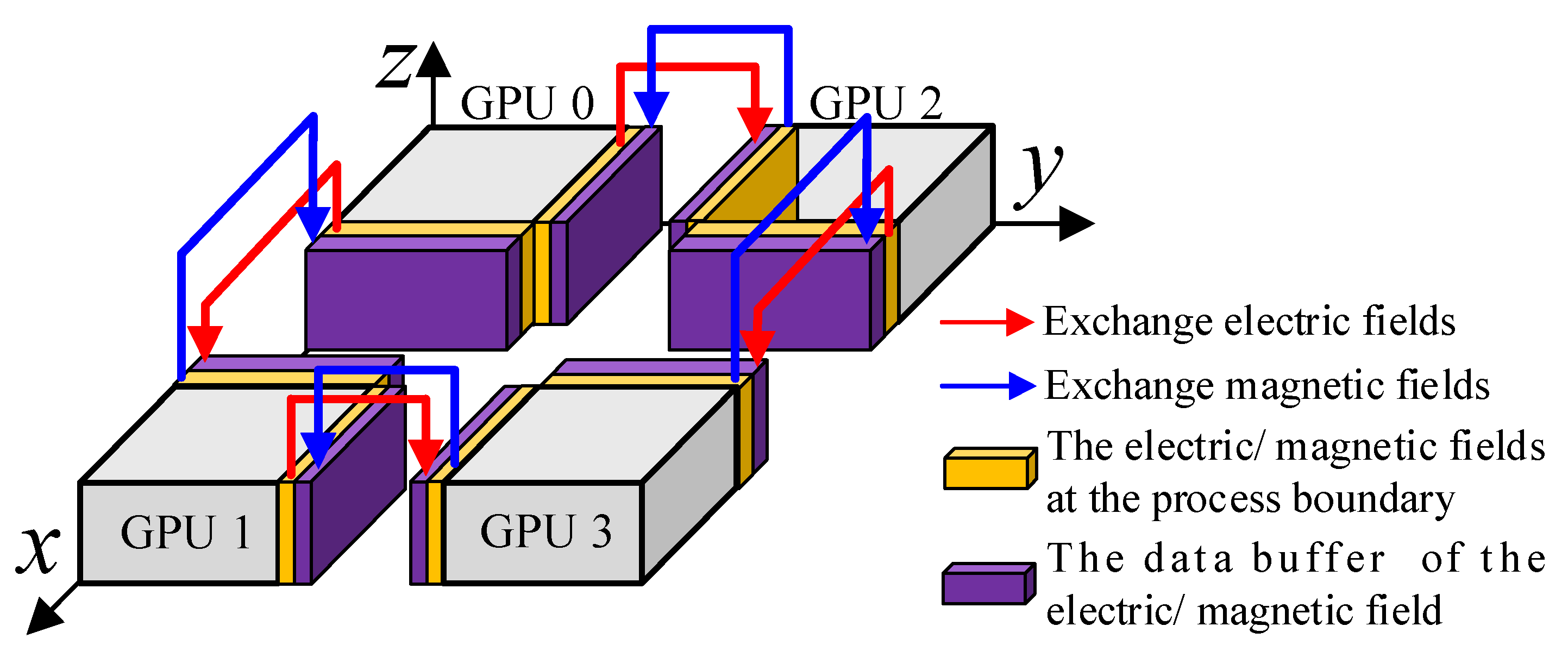
3.2.2. GPUs Communicate Directly Based on NCCL

The NCCL technology can directly transmit data between multiple GPU devices without the help of a CPU. A data transmission scheme based on the NCCL technology is shown in Figure 5. The GPU in the node can carry out point-to-point data interaction through the NVLink. For inter-node GPUs, this paper uses the NCCL technology combined with an Infiniband network card to exchange data between the GPUs directly.
When applying the NCCL technology in GPU-parallel FDTD methods, the NCCL needs to be initialized first. Specifically, we use ncclGetUniqueId to create a unique communication identifier ncclUniqueId, and initialize the communicator using this identifier for each process through ncclCommInitRank.
After the initialization of the communicator is completed, the environment variable export NCCL_P2P_EVEL = NVL can be set to specify that the NCCL prioritizes the NVLink when building communication paths, ensuring that communication is conducted through the NVLink as much as possible. In GPU clusters with an NVLink interconnection, this setting can significantly improve the communication efficiency and reduce data transmission bottlenecks, especially suitable for bandwidth-sensitive scenarios, such as boundary data exchange in distributed FDTD methods.
For data exchange between FDTD subdomain segmentation sections, the commonly used communication functions are ncclSend and ncclRecv, which are blocking communication methods that can ensure the orderliness of data exchange and naturally meet the synchronization requirements of FDTD time step advancement. To improve communication efficiency, multiple communication operations can be packaged into one group communication through ncclGroupStart and ncclGroupEnd. For example, boundary data exchange operations from the X-, Y-, and Z-directions can be merged into the same communication group to reduce communication calls and improve bandwidth utilization.
In addition, to further optimize performance, the boundary data buffers in the three directions can be packaged into a continuous memory block at the sending end, and sent to the target GPU through only one transfer operation, and then unpacked at the receiving end. This method significantly reduces the frequency and overhead of data transmission, improving the overall communication efficiency.
At the end of the simulation or at a specific moment when the data from each GPU need to be aggregated, ncclAllGather can be used to collect the extrapolated cross-sectional data from the various devices into the video memory of each GPU, facilitating subsequent result processing and visualization. During the initialization, ncclBroadcast can also be used to synchronize the simulation parameters of the main process with the other GPUs, ensuring that all the processes perform their calculations under the same configuration.
It should be noted that the NCCL can only transmit continuous memory regions, while the FDTD’s subdomain data are usually continuous when divided along the X-direction, resulting in discontinuous data access when divided along the Y/Z-direction. Therefore, for achieving efficient communication, we have designed an auxiliary buffering mechanism. A continuous buffer region (the purple area in Figure 5) is opened for each subdomain in the boundary direction, which is responsible for packaging and unpacking the boundary data. This mechanism effectively avoids the unnecessary overhead of manual packaging before each communication, improving the overall efficiency and maintainability of communication.
The time-domain stepping process of the GPU-based FDTD parallel algorithm is as follows:
(a)
Send the magnetic field H data of the yellow region to the purple data buffer of the adjacent subdomain;
(b)
Electric field E iteration;
(c)
Send the electric field data of the yellow region to the purple data buffer of the adjacent subdomain;
(d)
Magnetic field iteration.
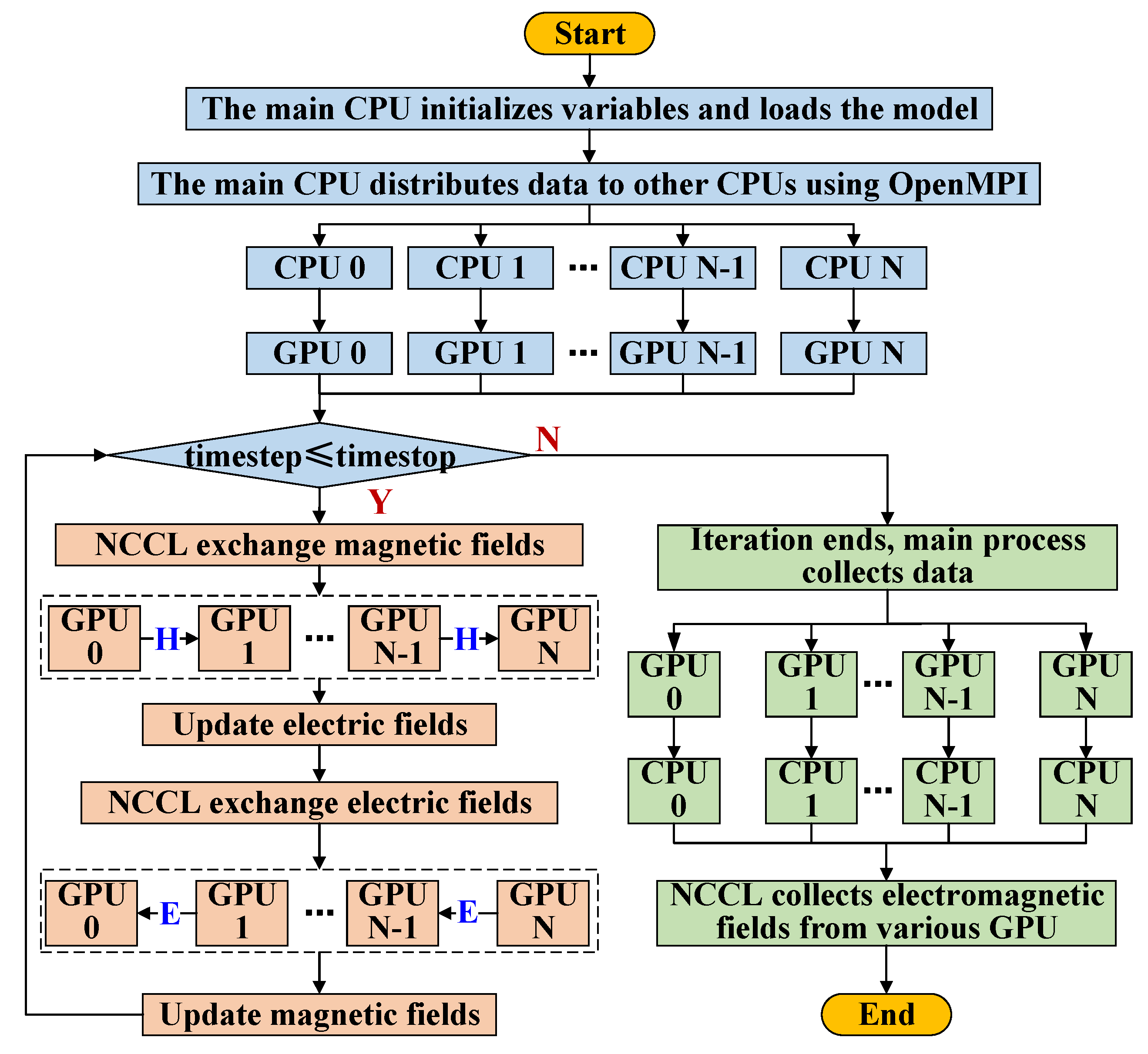
Repeat steps (a–d) until the time step iteration is completed.
The flow chart of the FDTD algorithm based on clustered GPUs is shown in Figure 6.
The above flow chart demonstrates a computing mode where the CPU dominates and the GPU collaborates. The program’s flowchart visually depicts the key steps of this process.
(a)
The system starts computing tasks by creating CPU processes that match the number of available GPUs using OpenMPI technology. At this stage, the main process of the CPU plays a crucial role, and is responsible for initializing all the variable information required throughout the entire computation process. This variable information is essential for the subsequent calculations, as it ensures the accuracy and consistency of the calculations.
(b)
The CPU main process performs load balancing and partitioning of the computing domain based on the number of processes. This step aims to optimize the allocation of computing resources, ensuring that each CPU process can handle an appropriate amount of data, thereby improving the overall computing efficiency. A segmented computing domain is allocated to each CPU process to prepare for the subsequent computing work. The model data for each CPU process are efficiently copied to the corresponding GPU global memory.
(c)
The GPUs fully utilize their powerful computing power by mapping each Yee cell onto a thread and carrying out the computing work in parallel. This calculation mode not only greatly improves the calculation speed, but also ensures the accuracy of the calculation. At each time step, the interaction of electric field data and magnetic field data between the GPUs is achieved through the NCCL technology. The NCCL technology provides an efficient and reliable solution for data communication between GPUs, ensuring the accuracy and consistency of data.
(d)
Finally, the collection of the calculation results is the responsibility of OpenMPI. OpenMPI allows for direct access to each GPU storage space, enabling the efficient collection of the computation results.
From the above flowchart, it can be seen that the CPU only participates in task allocation and data collection, and only the GPUs participate in the time iteration process. Compared with the traditional mode of forwarding data through the CPU, the NCCL can directly transmit data between multiple GPU devices without relying on the CPU for data transfer. This method not only greatly reduces the delays from data transmission, but also optimizes the process according to the communication topology structure, fully utilizes the hardware resources of the NVIDIA GPUs, and improves the communication efficiency and computing performance. Therefore, the NCCL plays an important role in multi-GPU computing environments, especially in scenarios that require efficient and large-scale parallel computing, greatly improving the overall computing and communication performance.
This paper uses speedup and parallel efficiency to evaluate the parallel effect of the FDTD algorithm of distributed cluster GPUs. The speedup is defined as
S p e e d u p = t C P U / t G P U
where t C P U is the CPU calculation time and t G P U is the GPU calculation time. Parallel efficiency is defined as
E f f i c i e n c y = t G P U 1 / N G P U t G P U × 100 %
where t G P U 1 is the calculation time of a single GPU and N G P U is the number of GPUs used.

4. Simulation Results and Analysis

The hardware environment used in this paper is a dual-node cluster environment. The cluster contains four NVIDIA Tesla P100 video cards, each with 16 GB of video memory. Each node has two video cards and is connected through IB network cards. Each node in the cluster is configured with two AMD EPYC™ 7713 CPUs.
Calculation cases are given below to illustrate the accuracy and efficiency of the scheme.

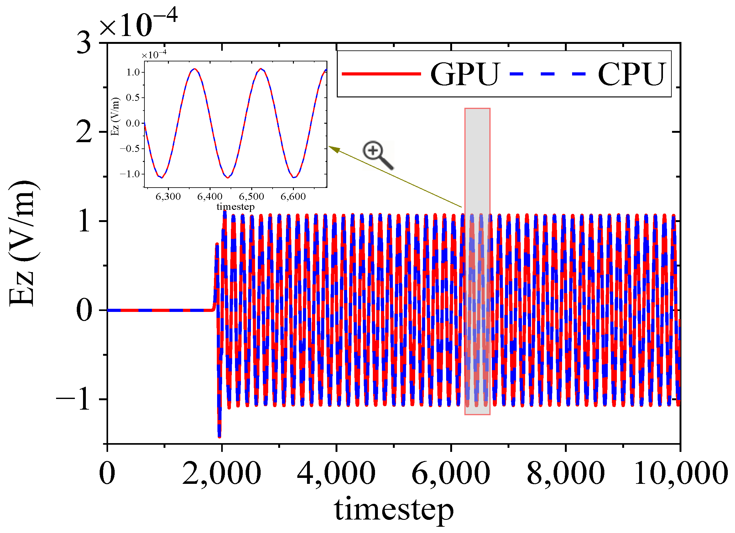
4.1. Free-Space Electric Dipole Radiation

The computational space is discretized into 1000 Δ x × 300 Δ y × 300 Δ z , and the total number of grids is 90 million. The excitation source is an electric dipole in the z-direction located in the center of the calculation region. It is a time–harmonic field with a frequency of 300 MHz. In this example, the FDTD algorithm based on a CPU and GPU is used to calculate the snapshot of the z-component of the electric field (Ez) for the xoy cross-section at the 3000th time step, as shown in Figure 7. The results of the CPU and GPU at a monitoring point are compared in Figure 8, which proves that the FDTD calculation results based on a GPU are accurate.
To verify the parallel efficiency of the GPU, Table 1 shows the calculation time, speedup, and parallel efficiency of the CPU, single GPU, dual GPUs at a dual node, and four GPUs at a dual node. It can be seen from Table 1 that the calculation acceleration ratio of a single GPU is about eight times. With the increase in GPU cards, the acceleration ratio shows a linear growth trend. In addition, the NCCL technology shortens the communication time between the GPUs, thereby improving the computational efficiency.

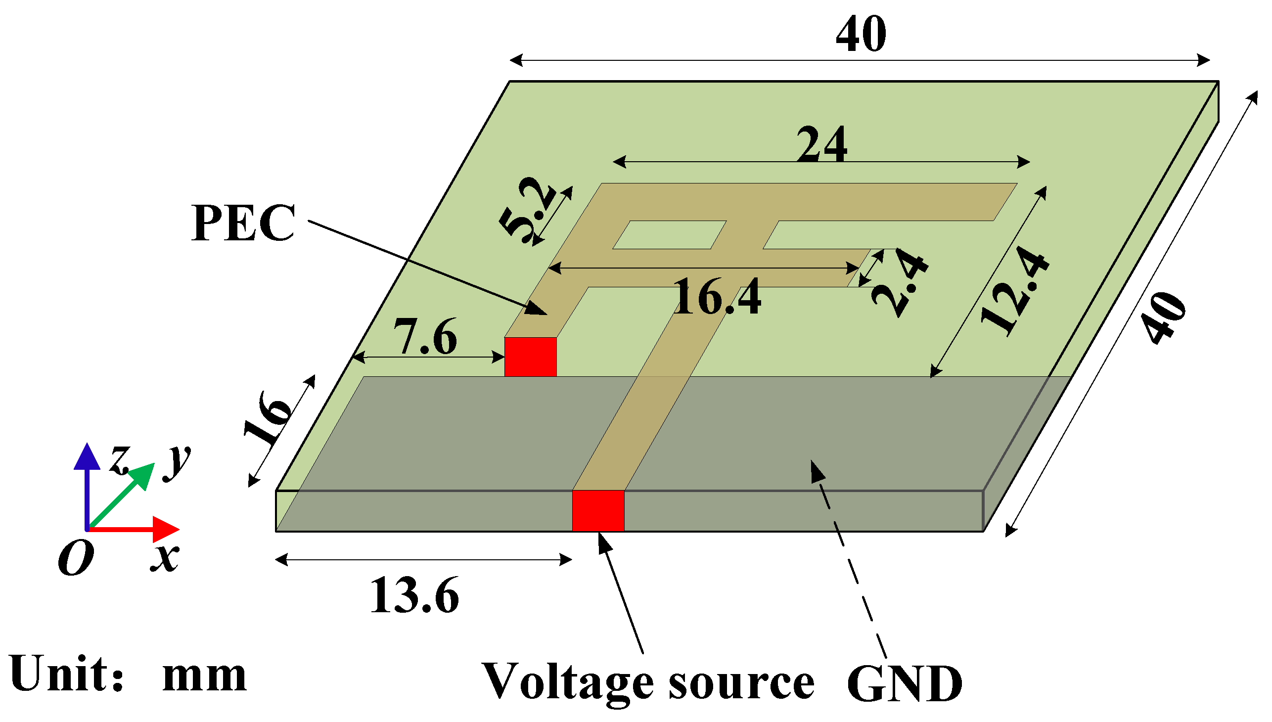
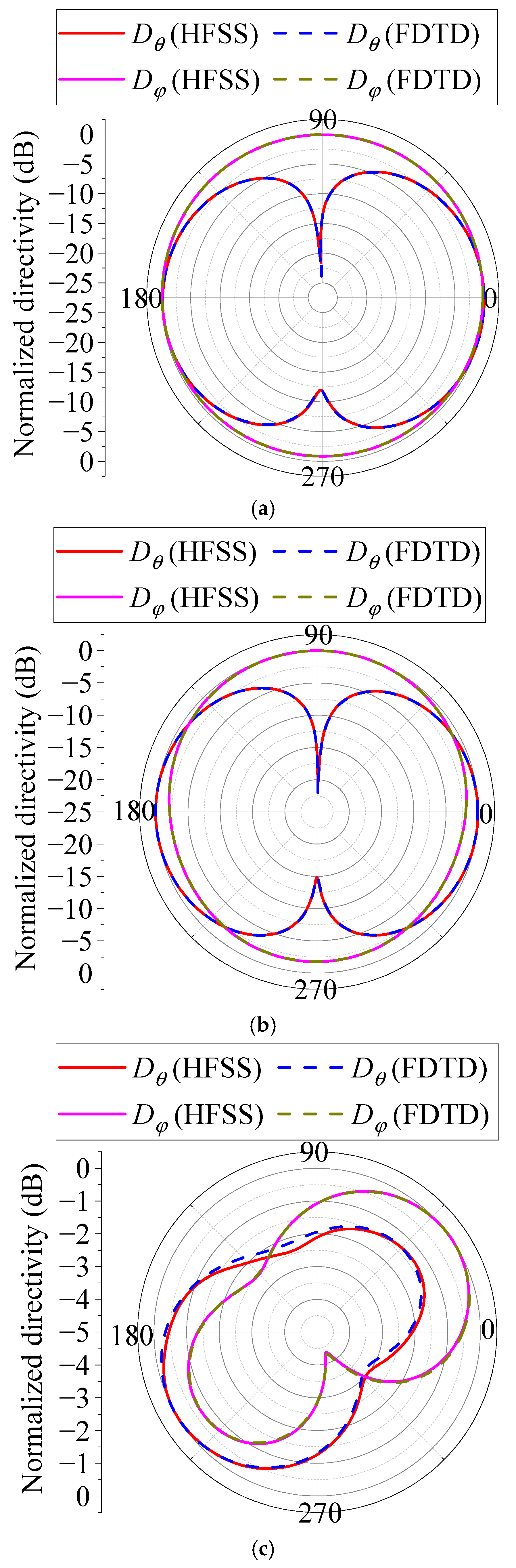
4.2. Antenna Simulation

The radiation direction of an inverted-F antenna is simulated to illustrate the accuracy and efficiency of the scheme. The inverted-F antenna is etched onto a 40 mm × 40 mm substrate with a relative permittivity of 2.2 and a thickness of 0.787 mm. The antenna design size is shown in Figure 9. At the antenna port, a voltage source is used for excitation. The internal resistance of the voltage source is 50   Ω and the voltage is 1 V. The far-field radiation pattern of the antenna at a 2.4 GHz operating frequency is calculated using HFSS 2022 R1 and GPU-based FDTD parallel algorithms. The grid discrete size of the FDTD algorithm is Δ x = 0.133   mm , Δ y = 0.133   mm , Δ z = 0.262   mm , and the calculation results are shown in Figure 10. It can be seen that the calculation results of the FDTD parallel algorithm based on a GPU and HFSS are in good agreement, which proves the calculation accuracy of the proposed parallel algorithm. Table 2 shows the calculation time, speedup, and parallel efficiency under the conditions of a CPU, a single GPU, dual GPUs at a dual node, and four GPUs at a dual node to verify the validity of the GPU-based FDTD method. In this example, a single GPU can obtain about 16 times the speedup compared with the CPU. Also, with the increase in the GPU number, the computational efficiency gradually decreases, which is caused by the increased communication time. The NCCL technology presented in this article can significantly reduce the communication time and improve the computational efficiency.

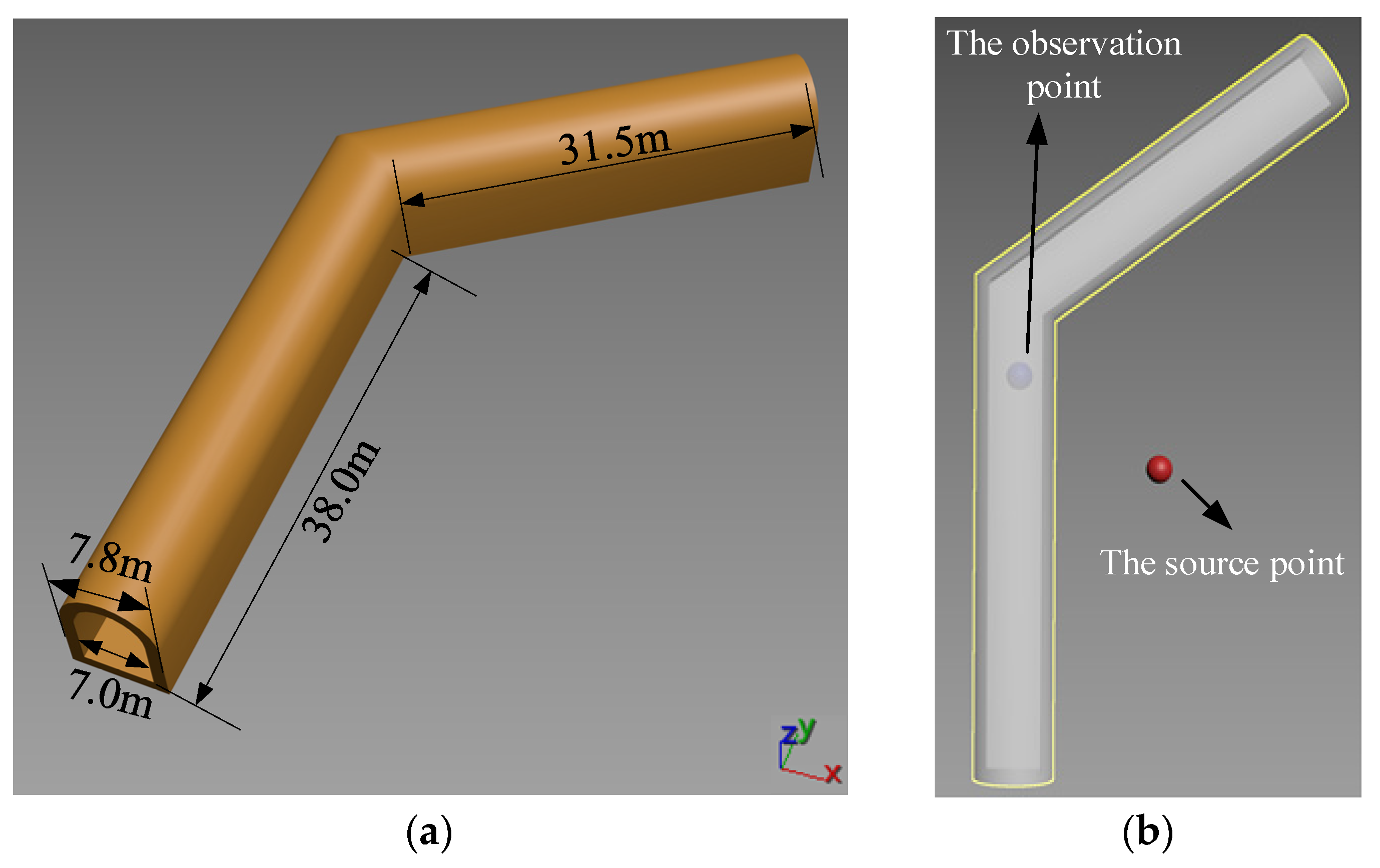
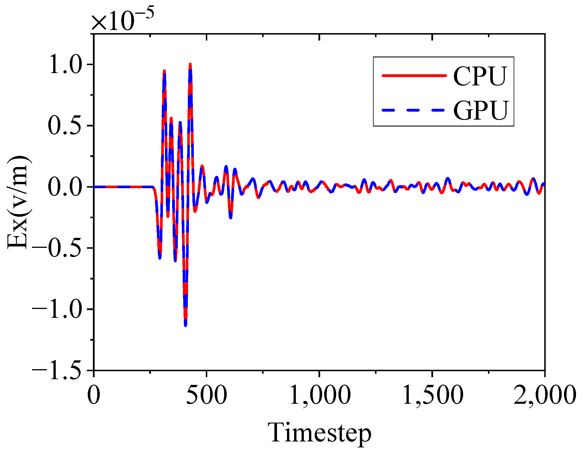
4.3. The Radio Wave Propagation Problem

In this example, radio wave propagation in a tunnel is simulated. The structure and dimensions of the tunnel are shown in Figure 11a, and the permittivity and conductivity for the tunnel are ε r = 4 and σ = 0   S / m , respectively. A schematic diagram of the source and observation point positions is shown in Figure 11b. The excitation source is a Gaussian pulse. An FDTD algorithm based on a CPU and GPU is used to calculate the x-component electric field (Ex) of the observation point, as shown in Figure 12, which exhibits good consistency. Similar to the two other examples, the calculation time, speedup, and parallel efficiency under the conditions of a CPU, a single GPU, dual GPUs at a dual node, and four GPUs at a dual node are tabulated in Table 3, which proves the efficiency of the proposed method.

5. Conclusions

In this paper, the NCCL technology is applied to a GPU-based FDTD parallel algorithm. This method can directly transfer data between GPUs without the help of CPU forwarding, which greatly improves the communication efficiency between the GPUs. The numerical results show that the proposed method is accurate and efficient and can provide a new idea and technique for high-performance computing based on GPUs, thereby demonstrating the practical implications of our research. The following main conclusions are drawn from this research:
(1)
Compared with an FDTD algorithm on a CPU platform, an FDTD algorithm based on GPUs can significantly improve the computational efficiency.
(2)
Compared with traditional CPU forwarding for GPUs communication, GPUs direct communication based on the NCCL technology can improve the computational efficiency.
(3)
Due to hardware resource limitations, this paper only performed calculations on four GPUs. As the number of GPUs increases, the efficiency improvement of this new communication mode becomes more significant.
This paper is the first to apply the NCCL technology to an FDTD algorithm across GPU nodes, reducing the communication latency and improving the overall simulation efficiency. The implementation of this technology can greatly enhance the application scope of FDTD algorithms, providing a technical foundation for the efficient parallel implementation of FDTD algorithms and other electromagnetic algorithms. In addition, this method has not been widely applied in computational electromagnetics, so parallelizing different electromagnetic algorithms will be our next focus of work.

Author Contributions

Conceptualization, X.H. (Xinbo He) and B.W.; methodology, S.M.; validation, X.H. (Xudong Han); formal analysis, X.H. (Xinbo He) and B.W.; investigation, S.M.; data curation, S.M. and X.H. (Xinbo He); writing—original draft preparation, S.M. and X.H. (Xinbo He); writing—review and editing, X.H. (Xinbo He); visualization, X.H. (Xinbo He); supervision, X.H. (Xinbo He) and B.W.; funding acquisition, X.H. (Xinbo He) and B.W. All authors have read and agreed to the published version of the manuscript.

Funding

This research was supported by the National Natural Science Foundation of China (Grant Nos. 62201411, 62371378, and 62471352); Fundamental Research Funds for the Central Universities (XJSJ24035); and the National Key Laboratory of Electromagnetic Environment (JCKY2024210C61424030201).

Institutional Review Board Statement

Not applicable.

Informed Consent Statement

Not applicable.

Data Availability Statement

The data are only available on request due to restrictions on privacy.

Conflicts of Interest

The authors declare no conflicts of interest.

Abbreviations

The following abbreviations are used in this manuscript:
FDTDFinite-Difference Time Domain
GPUGraphic Process Unit
CUDACompute Unified Device Architecture
NCCLCollective Communications Library
CPUCentral Processing Unit

References

  1. Teixeira, F. A summary review on 25 years of progress and future challenges in FDTD and FETD techniques. Appl. Comput. Electrom. 2010, 25, 1–14. [Google Scholar]
  2. Yang, M.; Liu, K.; Zheng, K.; Wu, Q.; Wei, G. A Hybrid SI-FDTD Method to Analyze Scattering Fields From Underwater Complex Targets. IEEE Trans. Antennas Propag. 2024, 72, 7407–7412. [Google Scholar] [CrossRef]
  3. Yang, M.; Wu, Q.; Zheng, K.; Zhang, S.; Wei, G. Radiation Field Distribution Above Sea Surface of Underwater Microstrip Antenna Array. IEEE Antennas Wirel. Propag. Lett. 2024, 23, 858–862. [Google Scholar] [CrossRef]
  4. He, X.; Chen, M.; Wei, B. A Hybrid Algorithm of 3-D Explicit Unconditionally Stable FDTD and Traditional FDTD Methods. IEEE Antennas Wirel. Propag. Lett. 2024, 23, 4653–4657. [Google Scholar] [CrossRef]
  5. Yee, K. Numerical solution of initial boundary value problems involving Maxwell’s equations in isotropic media. IEEE Trans. Antennas Propag. 1966, 14, 302–307. [Google Scholar]
  6. Warren, C.; Giannopoulos, A.; Gray, A.; Giannakis, I.; Patterson, A.; Wetter, L. A CUDA-based GPU engine for gprMax: Open source FDTD electromagnetic simulation software. Comput. Phys. Commun. 2018, 237, 208–218. [Google Scholar] [CrossRef]
  7. Jia, C.; Guo, L.; Yang, P. EM scattering from a target above a 1-D randomly rough sea surface using GPU-based parallel FDTD. IEEE Antennas Wirel. Propag. Lett. 2014, 14, 217–220. [Google Scholar] [CrossRef]
  8. Chi, J.; Liu, F.; Weber, E.; Li, Y.; Crozier, S. GPU-accelerated FDTD modeling of radio-frequency field–tissue interactions in high-field MRI. IEEE Trans. Bio-Med. Eng. 2011, 58, 1789–1796. [Google Scholar]
  9. Gunawardana, M.; Kordi, B. GPU and CPU-based parallel FDTD methods for frequency-dependent transmission line models. IEEE Lett. Electromag. 2022, 4, 66–70. [Google Scholar] [CrossRef]
  10. Kim, K.; Kim, K.; Park, Q. Performance analysis and optimization of three-dimensional FDTD on GPU using roofline model. Comput. Phys. Commun. 2011, 182, 1201–1207. [Google Scholar] [CrossRef]
  11. Zygiridis, T.; Kantartzis, N.; Tsiboukis, T. GPU-accelerated efficient implementation of FDTD methods with optimum time-step selection. IEEE Trans. Magn. 2014, 50, 477–480. [Google Scholar] [CrossRef]
  12. Zhang, B.; Xue, Z.; Ren, W.; Li, W.; Sheng, X. Accelerating FDTD algorithm using GPU computing. In Proceedings of the 2011 IEEE International Conference on Microwave Technology & Computational Electromagnetics, Beijing, China, 22–25 May 2011; IEEE: New York, NY, USA, 2011; pp. 410–413. [Google Scholar]
  13. Livesey, M.; Stack, J.; Costen, F.; Nanri, T.; Nakashima, N.; Fujino, S. Development of a CUDA implementation of the 3D FDTD method. IEEE Antennas Propag. Mag. 2012, 54, 186–195. [Google Scholar] [CrossRef]
  14. Feng, J.; Fang, M.; Deng, X.; Li, Z.; Xie, G.; Huang, Z. FDTD Modeling of Nonlocality in Nanoantenna Accelerated by CPU-GPU Heterogeneous Architecture and Subgridding Techniques. IEEE Trans. Antennas Propag. 2024, 72, 1708–1720. [Google Scholar] [CrossRef]
  15. Cannon, P.; Honary, F. A GPU-accelerated finite-difference time-domain scheme for electromagnetic wave interaction with plasma. IEEE Trans. Antennas Propag. 2015, 63, 3042–3054. [Google Scholar] [CrossRef]
  16. Liu, S.; Zou, B.; Zhang, L.; Ren, S. A multi-GPU accelerated parallel domain decomposition one-step leapfrog ADI-FDTD. IEEE Antennas Wirel. Propag. Lett. 2020, 19, 816–820. [Google Scholar] [CrossRef]
  17. Feng, J.; Song, K.; Fang, M.; Chen, W.; Xie, G.; Huang, Z. Heterogeneous CPU-GPU Accelerated Subgridding in the FDTD Modelling of Microwave Breakdown. Electronics 2022, 11, 3725. [Google Scholar] [CrossRef]
  18. Liu, S.; Zou, B.; Zhang, L.; Ren, S. Heterogeneous CPU+ GPU-accelerated FDTD for scattering problems with dynamic load balancing. IEEE Trans. Antennas Propag. 2020, 68, 6734–6742. [Google Scholar] [CrossRef]
  19. Baumeister, P.; Hater, T.; Kraus, J.; Wahl, P. A performance model for GPU-accelerated FDTD applications. In Proceedings of the 2015 IEEE 22nd International Conference on High Performance Computing (HiPC), Bengaluru, India, 16–19 December 2015; IEEE: New York, NY, USA, 2016; pp. 185–193. [Google Scholar]
  20. Chen, Y.; Zhu, P.; Wen, W.; Jiang, J. Accelerating 3D acoustic full waveform inversion using a multi-GPU cluster. IEEE Trans. Geosci. Remote Sens. 2023, 61, 5913815. [Google Scholar]
  21. Kim, K.; Park, Q. Overlapping computation and communication of three-dimensional FDTD on a GPU cluster. Comput. Phys. Commun. 2012, 183, 2364–2369. [Google Scholar] [CrossRef]
  22. Foley, D.; Danskin, J. Ultra-Performance Pascal GPU and NVLink Interconnect. IEEE Micro 2017, 37, 7–17. [Google Scholar] [CrossRef]
  23. Awan, A.; Hamidouche, K.; Venkatesh, A. Efficient large message broadcast using NCCL and CUDA-aware MPI for deep learning. In Proceedings of the 23rd European MPI Users’ Group Meeting, Edinburgh, UK, 25–28 September 2016; ACM: New York, NY, USA, 2016; pp. 15–22. [Google Scholar]
  24. Boureima, I.; Bhattarai, M.; Eren, M.; Skau, E.; Romero, P.; Eidenbenz, S.; Alexandrov, B. Distributed out-of-memory NMF on CPU/GPU architectures. J. Supercomput. 2024, 80, 3970–3999. [Google Scholar] [CrossRef]
Figure 1. The FDTD Yee cell.
Applsci 15 04834 g001
Figure 2. Internal structure diagram of CUDA memory.
Applsci 15 04834 g002
Figure 3. FDTD calculation region division scheme.
Applsci 15 04834 g003
Figure 4. GPUs communicate indirectly through the CPU.
Applsci 15 04834 g004
Figure 5. GPUs communicate directly based on NCCL.
Applsci 15 04834 g005
Figure 6. The flow chart of the FDTD algorithm based on clustered GPUs.
Applsci 15 04834 g006
Figure 7. The snapshot of Ez for the xoy cross-section at the 3000th time step: (a) CPU and (b) GPU.
Applsci 15 04834 g007
Figure 8. The waveform of Ez at the monitoring point.
Applsci 15 04834 g008
Figure 9. Structural dimensions of inverted-F antenna.
Applsci 15 04834 g009
Figure 10. Antenna far-field radiation direction diagram: (a) φ = 0 ° , (b) φ = 90 ° , and (c) θ = 90 ° .
Applsci 15 04834 g010
Figure 11. Radio wave propagation in a tunnel. (a) The three-dimensional structure of the tunnel. (b) A schematic diagram of the source and observation point positions.
Applsci 15 04834 g011
Figure 12. The waveform of Ex at the observation point in the tunnel.
Applsci 15 04834 g012
Table 1. Calculation time, speedup, and efficiency under different hardware conditions of example 4.1.
HardwareCPUSingle GPUDual GPUs at Dual NodeFour GPUs at Dual Node
Without NCCLWith NCCLWithout NCCLWith NCCL
Time (s)18,792238012751211658604
Speedup17.914.915.528.631.1
Efficiency\100.0%94.3%98.1%90.5%98.4%
Table 2. Calculation time, speedup, and efficiency under different hardware conditions of example 4.2.
HardwareCPUSingle GPUDual GPUs at Dual NodeFour GPUs at Dual Node
Without NCCLWith NCCLWithout NCCLWith NCCL
Time (s)20,7921308680658351332
Speedup115.930.631.659.262.6
Efficiency\100.0%96.2%99.4%93.1%98.4%
Table 3. Calculation time, speedup, and efficiency under different hardware conditions of example 4.3.
HardwareCPUSingle GPUDual GPUs at Dual NodeFour GPUs at Dual Node
Without NCCLWith NCCLWithout NCCLWith NCCL
Time (s)25402031051025552
Speedup112.624.224.946.248.8
Efficiency\100.0%96.0%98.8%91.7%96.8%
Disclaimer/Publisher’s Note: The statements, opinions and data contained in all publications are solely those of the individual author(s) and contributor(s) and not of MDPI and/or the editor(s). MDPI and/or the editor(s) disclaim responsibility for any injury to people or property resulting from any ideas, methods, instructions or products referred to in the content.

